EPFL SV PTBIOP BASICS IN LIGHT MICROSCOPY · Hal lamp stageaperture condenser Hg lamp ... Change in...
80
BASICS IN LIGHT MICROSCOPY INTERNAL COURSE 2014 13 TH JANUARY
Transcript of EPFL SV PTBIOP BASICS IN LIGHT MICROSCOPY · Hal lamp stageaperture condenser Hg lamp ... Change in...

BIOIMAGING AND
OPTICS PLATFORM
EPFL–SV–PTBIOP
BASICS IN
LIGHT MICROSCOPY
INTERNAL COURSE 2014
13TH JANUARY

BIOIMAGING AND
OPTICS PLATFORM
EPFL–SV–PTBIOP
OVERVIEW
1. Motivation
2. Basic in optics
3. How microscope works
4. Illumination and resolution
5. Microscope optics
6. Contrasting methods
-2-

BIOIMAGING AND
OPTICS PLATFORM
EPFL–SV–PTBIOP
MOTIVATION
• Why do we need microscopy?
• Main issues of microscopy
-3-

BIOIMAGING AND
OPTICS PLATFORM
EPFL–SV–PTBIOP
The name:
Microscopy
greek
mikros= small
skopein= to observe
“Observation of small objects”
-4-

BIOIMAGING AND
OPTICS PLATFORM
EPFL–SV–PTBIOP
HUMAN EYE
-5-
Normal viewing distance - 250 mm
Angular resolution amin ≈ 1’
Spatial resolution hmin ≈ 80 mm
Nodal distance -17 mm
Average retinal cell distance 1.5 mm
Spectral range 400 nm - 800 nm
Can resolve contrast about 5%
High dynamic range – 10 decades
Max sensitivity at 505 nm (night, rods)
Max sensitivity at 555 nm (day, cones)
More sensitive to color than to intensity
Most perfect sensor for light detection up to now

BIOIMAGING AND
OPTICS PLATFORM
EPFL–SV–PTBIOP
MAIN ISSUES OF
MICROSCOPY
low contrast low resolution
low magnification

BIOIMAGING AND
OPTICS PLATFORM
EPFL–SV–PTBIOP
Only fulfillment of these three conditions allows translation of
information as accurately as possible from object into an image
which represents that object.
MAIN ISSUES OF
MICROSCOPY
Contrast Magnifi-
cation
Resolu-
tion

BIOIMAGING AND
OPTICS PLATFORM
EPFL–SV–PTBIOP
Light is the messenger and transports the object information from the
specimen through the microscope
Light translates the object information into a microscopic image of the
specimen
The observer observes the microscopic image of the specimen not the
specimen itself !
Only best management of the light allows translation of information as
accurately as possible from object into an image which represents that
object!
IMAGE FORMATION

BIOIMAGING AND
OPTICS PLATFORM
EPFL–SV–PTBIOP
MAGNIFYING GLASS
Magnifier increases the angular size of the object
M=a2/a1
Magnification is defined by focal distance of lens
M=250/f
Maximum magnification of magnifying glass is 10x-20x
a1 a2
250 mm
f object virtual image

BIOIMAGING AND
OPTICS PLATFORM
EPFL–SV–PTBIOP
GEOMETRICAL OPTICS THIN LENS
Focal
point
Focal length f
Principal plane
optical
axis
Characterization of a lens:
Focal length: f=50 mm=0.05 m
Power: 1/f =20 m-1 = 20 dioptre

BIOIMAGING AND
OPTICS PLATFORM
EPFL–SV–PTBIOP
GEOMETRICAL OPTICS THIN LENS
Focal
point
Focal length f
Principal plane
optical
axis
Working principle of lenses:
•Refraction
•Curvature
BIOIMAGING AND
OPTICS PLATFORM
EPFL–SV–PTBIOP
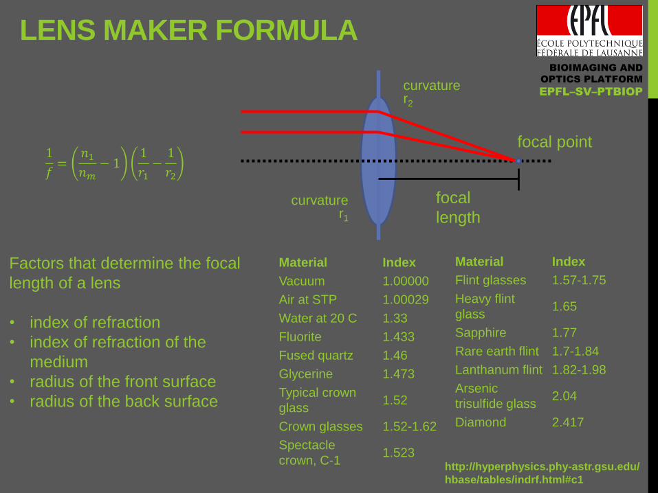
LENS MAKER FORMULA
1
𝑓=𝑛1𝑛𝑚− 1
1
𝑟1−1
𝑟2
curvature r1
curvature r2
focal point
focal
length
Material Index
Vacuum 1.00000
Air at STP 1.00029
Water at 20 C 1.33
Fluorite 1.433
Fused quartz 1.46
Glycerine 1.473
Typical crown
glass 1.52
Crown glasses 1.52-1.62
Spectacle
crown, C-1 1.523
Material Index
Flint glasses 1.57-1.75
Heavy flint
glass 1.65
Sapphire 1.77
Rare earth flint 1.7-1.84
Lanthanum flint 1.82-1.98
Arsenic
trisulfide glass 2.04
Diamond 2.417
http://hyperphysics.phy-astr.gsu.edu/
hbase/tables/indrf.html#c1
Factors that determine the focal
length of a lens
• index of refraction
• index of refraction of the
medium
• radius of the front surface
• radius of the back surface

BIOIMAGING AND
OPTICS PLATFORM
EPFL–SV–PTBIOP
SIMPLE LENS TYPES

BIOIMAGING AND
OPTICS PLATFORM
EPFL–SV–PTBIOP
GEOMETRICAL OPTICS THIN LENS- IMAGE FORMATION
Principal plane
optical
axis
f -f
object
image
s0
s1
1
𝑓=1
𝑠0+1
𝑠1
𝑠0 = 5.35 𝑐𝑚 𝑠1 = 14.1 𝑐𝑚 𝑓 = 3.8 𝑐𝑚
1𝑠 0 = 0.19 𝑐𝑚
−1 1𝑠 1 = 0.07 𝑐𝑚
−1 1𝑓 = 0.26 𝑐𝑚
−1
1 cm

BIOIMAGING AND
OPTICS PLATFORM
EPFL–SV–PTBIOP
GEOMETRICAL OPTICS THIN LENS- VIRTUAL IMAGE FORMATION
Principal plane
optical
axis
f -f
object
image

BIOIMAGING AND
OPTICS PLATFORM
EPFL–SV–PTBIOP
GEOMETRICAL OPTICS TELESCOPE
optical
axis
f2 l1
l2
f1 =-f2 -f1
d=f1+f2
𝑀 =𝑓2𝑓1

BIOIMAGING AND
OPTICS PLATFORM
EPFL–SV–PTBIOP
HOW MICROSCOPE WORKS
Compound microscope
Convergent and infinite beam paths
Components of microscope

BIOIMAGING AND
OPTICS PLATFORM
EPFL–SV–PTBIOP
Sample is placed in front of objective focal plane. Intermediate image
is formed by objective and is observed through eyepiece.
COMPOUND MICROSCOPE
CONVERGENT BEAM PATH

BIOIMAGING AND
OPTICS PLATFORM
EPFL–SV–PTBIOP
Convergent beam
Beam is focused differently
More aberrations
Parallel beam
Beam is only shifted
Less aberration
Presence of parallel light beam is microscope light path is important
for modern light microscope (for filters, and other optical elements)
DISADVANTAGE OF A
CONVERGENT BEAM PATH

BIOIMAGING AND
OPTICS PLATFORM
EPFL–SV–PTBIOP
The sample is placed in the focal plane of the objective. Parallel light beams are
focused by the tube lens. The intermediate image is observed through the eyepiece.
COMPOUND MICROSCOPE INFINITY-CORRECTED BEAM PATH

BIOIMAGING AND
OPTICS PLATFORM
EPFL–SV–PTBIOP
Objective are constructed of several high quality lenses.
For infinity corrected objective the specimen is in the focal plane
For not infinity corrected objectives the specimen is in front of the focal plane
OBJECTIVE

BIOIMAGING AND
OPTICS PLATFORM
EPFL–SV–PTBIOP
The eyepiece acts as a magnifier of the intermediate image
EYEPIECE

BIOIMAGING AND
OPTICS PLATFORM
EPFL–SV–PTBIOP
When the camera is used, the intermediate image is directly
projected on the camera chip (additionally an intermediate magnifier might be used).
CAMERA AS IMAGE
DETECTOR

BIOIMAGING AND
OPTICS PLATFORM
EPFL–SV–PTBIOP
camera
objective
eyepiece
filter cube
turret
Hal lamp
stage
condenser Hg lamp
field dia-
phragm (f)
DIC slider aperture
diaphragm (f)
focus
field dia-
phragm (t) aperture
diaphragm (t)
MAIN MICROSCOPE
COMPONENTS

BIOIMAGING AND
OPTICS PLATFORM
EPFL–SV–PTBIOP
Two independent
illumination paths:
• Transmission
• Fluorescence
Components for
contrasting methods:
• DIC
• Dark field
• Phase contrast
ANATOMY OF MICROSCOPE

BIOIMAGING AND
OPTICS PLATFORM
EPFL–SV–PTBIOP
Magnifying glass has a limited magnification of 10x-20x
Compound microscope makes two stage magnification
• initial magnification with objective
• further magnification with eyepiece
Compound microscope beam path designs
• finite – old microscopes
• infinity corrected – modern microscopes
There are several microscope types
• inverted
• upright
HOW MICROSCOPE WORKS
SUMMARY

BIOIMAGING AND
OPTICS PLATFORM
EPFL–SV–PTBIOP
ILLUMINATION AND RESOLUTION
Koehler illumination
Diffraction of light
Numerical aperture
Resolution

BIOIMAGING AND
OPTICS PLATFORM
EPFL–SV–PTBIOP
REQUIREMENTS FOR ILLUMINATION
Uniform over whole field of view
Has all angles accepted by objective
Allows optimize image brightness/contrast
Allows continuous change of intensity
Allows continuous change of field of view
Change in illumination and imaging parts do not effect each other
Realized in Kohler illumination

BIOIMAGING AND
OPTICS PLATFORM
EPFL–SV–PTBIOP
NAtot=NAobj+NAcond
ROLE OF CONDENSER IN IMAGE
FORMATION

BIOIMAGING AND
OPTICS PLATFORM
EPFL–SV–PTBIOP
Collector
gathers light from
light source
Condenser
directs light onto
the specimen
COLLECTOR AND CONDENSER

BIOIMAGING AND
OPTICS PLATFORM
EPFL–SV–PTBIOP
Image forming light path
(Observed with eyepiece)
1. Variable field diaphragm
2. Specimen plane
3. Intermediate image plane
4. Image plane (camera, retina)
Illumination light path
(Observed with Bertrand lens)
1. Lamp (filament, arc)
2. Condenser aperture diaphragm
3. Objective rear (back) focal plane
4. Eyepoint (exit pupil of microscope)
Conjugated = imaged onto each other
Has one diaphragm in every path
If light at given plane is focused in one
path, it is parallel in other path
CONJUGATED PLANES IN
OPTICAL MICROSCOPY

BIOIMAGING AND
OPTICS PLATFORM
EPFL–SV–PTBIOP
YOUNG: DOUBLE SLIT
EXPERIMENT
LIGHT-WAVE THEORY
Huygens-Fresnel Principle
Each point of a wavefront can be seen
as seed point for a new (circular) wave.
Richard Feynman:
[N]o-one has ever been able to define the difference between interference and
diffraction satisfactorily. It is just a question of usage, and there is no specific,
important physical difference between them.

BIOIMAGING AND
OPTICS PLATFORM
EPFL–SV–PTBIOP
RAYLEIGH-SOMMERFIELD
DIFFRACTION
Analytical solutions:
Fraunhofer:
small aperture, far-field
Kirchhoff-Fresnel:
small angle, paraxial

BIOIMAGING AND
OPTICS PLATFORM
EPFL–SV–PTBIOP
INTERFERENCE OF TWO POINT
SOURCES
2
2
22
2 1
t
f
vx
f
t
xiatxf
2exp),(
number wave2
k
frequencyangular 2
kv / velocity phase
)](exp[),( tkxiatxf
)]exp[)( ikxaxf
)sin()cos()( xkikxxf
nn SS
SSSS
krikr
rkikrrkikryf
sincos
)sin(cos)sin(cos)(2211
waves in phase
22
1dyrS
22)(2
dyarS

BIOIMAGING AND
OPTICS PLATFORM
EPFL–SV–PTBIOP
-4 -3 -2 -1 0 1 2 3 4
d / mm
INTERFERENCE CIRCULAR WAVE
20 mm
Wavelength: 500 nm
𝑦 𝑟 = 𝐴0 ∗ 𝑐𝑜𝑠 𝑘 ∗ 𝑟
𝑟 = (∆𝑥2+∆𝑦2)
𝑘 =2𝜋
𝜆
k:=wavenumber
Superposition of circular waves

BIOIMAGING AND
OPTICS PLATFORM
EPFL–SV–PTBIOP
INTERFERENCE OF TWO POINT
SOURCES
-20 -10 0 10 20
0
1
2
3
4
x / mm
I0
200 mm
𝐼 = 𝐼0 1 + 𝑘𝑑𝑠𝑖𝑛𝜃

BIOIMAGING AND
OPTICS PLATFORM
EPFL–SV–PTBIOP
INTERFERENCE MULTIPLE POINT
SOURCES
-40 -30 -20 -10 0 10 20 30 40
0
20
40
60
80
100/d /d /d
x / mm
/d
𝐼 = 𝐼0𝑠𝑖𝑛2𝑁(
𝜑2)
𝑠𝑖𝑛2(𝜑2)
𝜑 = 𝑘 ∙ 𝑑 ∙ 𝑠𝑖𝑛𝜃

BIOIMAGING AND
OPTICS PLATFORM
EPFL–SV–PTBIOP
DIIFRACTION SINGLE SLIT
0
10
20
30
40
d /
mm
Intensity
𝐼 = 𝐼0𝑠𝑖𝑛(Φ 2 )
Φ2
2

BIOIMAGING AND
OPTICS PLATFORM
EPFL–SV–PTBIOP
DIFFRACTION SINGLE SLIT
0
10
20
30
40
d /
mm
Intensity
400 nm
500 nm
600 nm
200 mm
0
10
20
30
40
d /
mm
Intensity
0
10
20
30
40
d /
mm
Intensity

BIOIMAGING AND
OPTICS PLATFORM
EPFL–SV–PTBIOP
DIFFRACTION SINGLE SLIT
0
10
20
30
40
d /
mm
Intensity
0
10
20
30
40
d /
mm
Intensity
0
10
20
30
40
d /
mm
Intensity
0
10
20
30
40
d /
mm
Intensity
500 nm slit:
20 µm
slit:
10 µm
slit:
5 µm
slit:
0.1 µm

BIOIMAGING AND
OPTICS PLATFORM
EPFL–SV–PTBIOP
LIGHT-WAVE THEORY FAR FIELD DIFFRACTION
Observation plane Parallel light
aperture 100 µm
distance R R>1.3 m
J. Fraunhofer (1787-1826)
Circular aperture
𝐼 = 𝐼0𝐽1(Φ2 )
Φ4
2
Φ = 𝑘 ∙ 𝑎 ∙ 𝑠𝑖𝑛𝜃
𝑠𝑖𝑛𝜃𝑚𝑖𝑛 = 1.22𝜆
𝑎
0
10
20
30
40
d /
mm
Intensity
Slit
𝐼 = 𝐼0𝑠𝑖𝑛(Φ 2 )
Φ2
2
Airy disk

BIOIMAGING AND
OPTICS PLATFORM
EPFL–SV–PTBIOP
A parallel beam falls on the screen with
pinholes.
Secondary spherical waves are formed on
each pinhole .
Interference results in several plane waves
DIFFRACTION OF LIGHT

BIOIMAGING AND
OPTICS PLATFORM
EPFL–SV–PTBIOP
0 -1 +1
1st order (d = 5 )
d = 2
0
+1
1st order (d = 1.5 )
d = 1
for small enough
structures a
first diffraction
maxima is
perpendicular to
the direct light
a md sin
Direction of diffraction maxima depends on wavelength and period
Bigger period results in smaller diffraction angle
Bigger wavelength results in bigger diffraction angle
DIFFRACTION ORDERS

BIOIMAGING AND
OPTICS PLATFORM
EPFL–SV–PTBIOP
0a
0sinanNA
518.1n
1n
! !
The NA defines how much light (brightness) and how many
diffraction orders (resolution) are captured by the objective.
NUMERICAL APERTURE OF
OBJECTIVE

BIOIMAGING AND
OPTICS PLATFORM
EPFL–SV–PTBIOP
ROLE OF IMMERSION
NA=nsina
Refractive indices:
Air - 1.003
Water - 1.33
Glycerol - 1.47
Oil - 1.52
Immersion media
increase the NA of an
objective or a condenser
by bringing the beams
with higher incidence
angle into the light path

BIOIMAGING AND
OPTICS PLATFORM
EPFL–SV–PTBIOP
- 46-
DIFFRACTION LIMITED
RESOLUTION
Ernst Abbe 1840-1905
𝑑 =𝜆
2 ∙ (𝑛 ∙ sin 𝜃)
𝑁𝐴 = (𝑛 ∙ sin 𝜃)
“According to Abbe, a detail with a particular spacing in the specimen is resolved when the numerical aperture (NA) of the objective lens is large enough to capture the first-order diffraction pattern produced by the detail at the wavelength employed. In order to fulfill Abbe's requirements, the angular aperture of the objective must be large enough to admit both the zeroth and first order light waves.” http://micro.magnet.fsu.edu/optics/timeline/people/abbe.html

BIOIMAGING AND
OPTICS PLATFORM
EPFL–SV–PTBIOP
DEPTH OF FIELD
- 47-
𝑑𝑡𝑜𝑡 =𝜆 ∙ 𝑛
𝑁𝐴2+𝑛
𝑀 ∙ 𝑁𝐴∙ 𝑒
Magnification Numerical
Aperture
Depth of
Field
(mm)
Image Depth
(mm)
4x 0.10 15.5 0.13
10x 0.25 8.5 0.80
20x 0.40 5.8 3.8
40x 0.65 1.0 12.8
60x 0.85 0.40 29.8
100x 0.95 0.19 80.0
Diffraction limited depth of field
Detection system

BIOIMAGING AND
OPTICS PLATFORM
EPFL–SV–PTBIOP
MODULATION/CONTRAST
- 48-
BIOIMAGING AND
OPTICS PLATFORM
EPFL–SV–PTBIOP
SPECTRAL TECHNIQUES
• Fourier transform
• Jean Baptiste Fourier (1768-1830): (Almost) every periodic function g(x) can be described as a sum of harmonic sinusoids.
• Non periodic functions can also be decribed as sums of sine and cosine functions (Fourier integral; infinitely many densley spaced frequencies)
• Signal Processing
• Discrete Fourier Transform (DFT); fast algorithm Fast Fourier Transform (FFT)
• Discrete Cosine Transformation (DCT)

BIOIMAGING AND
OPTICS PLATFORM
EPFL–SV–PTBIOP
FOURIER ANALYSIS/SYNTHESIS
𝑓 𝑥 =𝑎02 (𝑎𝑘 cos 𝑘𝜛𝑡 + 𝑏𝑘 sin(𝑘 𝜛 𝑡)
∞
𝑘=1
-10 -5 0 5 10
-1.0
-0.5
0.0
0.5
1.0
A
-10 -5 0 5 10
-1.0
-0.5
0.0
0.5
1.0
A
-10 -5 0 5 10
-1.0
-0.5
0.0
0.5
1.0
A
-10 -5 0 5 10
-1.0
-0.5
0.0
0.5
1.0
A

BIOIMAGING AND
OPTICS PLATFORM
EPFL–SV–PTBIOP
FOURIER ANALYSIS/SYNTHESIS
𝑓 𝑥 =𝑎02 (𝑎𝑘 cos 𝑘𝜛𝑡 + 𝑏𝑘 sin(𝑘 𝜛 𝑡)
∞
𝑘=1
-10 -5 0 5 10
-1.0
-0.5
0.0
0.5
1.0
-10 -5 0 5 10
-1.0
-0.5
0.0
0.5
1.0
-10 -5 0 5 10
-1.0
-0.5
0.0
0.5
1.0
-10 -5 0 5 10
-1.0
-0.5
0.0
0.5
1.0

BIOIMAGING AND
OPTICS PLATFORM
EPFL–SV–PTBIOP
FREQUENCY SPECTRUM
0 1 2 3 4 5 6 7 8 9 10
0.0
0.2
0.4
0.6
0.8
1.0
Am
plit
ud
e
𝑓 𝑥 =𝑎02 (𝑎𝑘 cos 𝑘𝜛𝑡 + 𝑏𝑘 sin(𝑘 𝜛 𝑡)
∞
𝑘=1
-10 -5 0 5 10
-1.0
-0.5
0.0
0.5
1.0

BIOIMAGING AND
OPTICS PLATFORM
EPFL–SV–PTBIOP
FAST FOURIER TRANSFORMATION
(FFT)

BIOIMAGING AND
OPTICS PLATFORM
EPFL–SV–PTBIOP
INVERSE FFT HIGH FREQUENCIES

BIOIMAGING AND
OPTICS PLATFORM
EPFL–SV–PTBIOP
INVERSE FFT LOW FREQUENCIES

BIOIMAGING AND
OPTICS PLATFORM
EPFL–SV–PTBIOP
MICROSCOPE OPTICS
Aberrations in optics
Objective engravings
Choice of magnification

BIOIMAGING AND
OPTICS PLATFORM
EPFL–SV–PTBIOP
OPTICAL ABERRATIONS
•Astigmatism (tangential and meridianal focus are different)
•Coma (image of dot is not symmetric)
•Distortion (parallel lines are not parallel in image)
•Curvature of the field (image of plane is not flat)
•Chromatic (different focus for different wavelength)
•Spherical (different focus for on and off axis beams)
It is desired to minimize aberrations by proper use of objectives with good aberration correction

BIOIMAGING AND
OPTICS PLATFORM
EPFL–SV–PTBIOP
SPHERICAL ABERRATION
Use cover slip 0.17 mm thick or
Use objective with correction ring
Avoid refraction index mismatch of immersion and mounting media

BIOIMAGING AND
OPTICS PLATFORM
EPFL–SV–PTBIOP
CHROMATIC ABERRATION
- 59-

BIOIMAGING AND
OPTICS PLATFORM
EPFL–SV–PTBIOP
OBJECTIVE TYPES
Objective
Type
Spherical
Aberration
Chromatic
Aberration
Field
Curvature
Achromat 1 Color 2 Colors No
Plan Achromat 1 Color 2 Colors Yes
Fluorite 2-3 Colors 2-3 Colors No
Plan Fluorite 3-4 Colors 2-4 Colors Yes
Plan Apochromat 3-4 Colors 4-5 Colors Yes

BIOIMAGING AND
OPTICS PLATFORM
EPFL–SV–PTBIOP
WORKING DISTANCE AND PARFOCAL
LENGTH
Parfocal distance
Distance from objective shoulder
till specimen plane
45 mm for most manufactures,
60 mm for Nikon CFI 60
Working distance
Distance from front edge of objective
till cover slip
Varies from several mm till several hundreds
micrometers. Special long working distance
objective are available.

BIOIMAGING AND
OPTICS PLATFORM
EPFL–SV–PTBIOP
NEOFLUAR optics is less color corrected than APOCHROMAT
W W Glyc Oil
Different immersion media under
various cover glass conditions
Range of cover glass thickness
Ph = phase contrast
(3 specifies matching condenser)
OBJECTIVES WITH CORRECTION
COLLARS

BIOIMAGING AND
OPTICS PLATFORM
EPFL–SV–PTBIOP
TOTAL MICROSCOPE MAGNIFICATION
Defined by magnification of objective, eyepiece and intermediate
magnification
Mtot=Mobj x Mint x Meyepiece
Objective magnification defined by focal lengths of tube lens and
objectives
Mobj=ftl/fobj
Tube lens has a standardized value for specific manufacture
Zeiss, Leica, Olympus 165 mm, Nikon 200 mm
Typical magnification rangies:
• Mobj: 2x÷100x
• Mint: 1.5x÷2.5x
• Mobj: 10x÷25x

BIOIMAGING AND
OPTICS PLATFORM
EPFL–SV–PTBIOP
USEFUL MAGNIFICATION RANGE
-
64
-
• Microscope resolution is limited by NA and wavelength.
• Enlargement of image does not necessarily resolve new features.
• Excessively large magnification is called empty magnification.
(The Airy disk on retina/camera should not exceed two
cell/pixel sizes).
Useful magnification = 500-1000 x NA of objective
Mobj Meyepiece NAobj Mtot Museful Magnification
10x 10x 0.35 100 175-350 low
40x 10x 0.70 400 350-700 ok
100x 10x 1.40 1000 700-1400 ok
100x 15x 1.40 1500 700-1400 empty

BIOIMAGING AND
OPTICS PLATFORM
EPFL–SV–PTBIOP
LIGHT BUDGET IN MICROSCOPE
Microscope has a lot of components in light path
• Microscope optics (T=0.8)
• Dichroic mirror (T=0.8)
• Filters (T=0.8)
• Objective, eyepiece (T=0.9)
• Objective collects light only within NA (T=0.3)
Typically only 10% of light arrives to CCD.
Use optics with antireflection coatings
Use high quality filters, dichroics
Use clean optics
Image brightness (transmission) ~ (NA/M)2
Image brightness (fluorescence) ~ NA4/M2
Use high NA objectives
Do not use unnecessary high magnification

BIOIMAGING AND
OPTICS PLATFORM
EPFL–SV–PTBIOP
Correct choice of microscope optics is the key to successful imaging
Pay attention to the engravings on objective and eyepiece
Optical aberrations can be minimized
• use well corrected optics or use green filter
• use cover slip 0.17 mm thick
• match refractive index of immersion media and specimen
Choose magnification carefully
• excessive magnification does not reveal new details
• moreover it deceases the brightness of the image
MICROSCOPE OPTICS SUMMARY

BIOIMAGING AND
OPTICS PLATFORM
EPFL–SV–PTBIOP
CONTRASTING METHODS
Dark field
Phase contrast
DIC
PlasDIC

BIOIMAGING AND
OPTICS PLATFORM
EPFL–SV–PTBIOP
Amplitude specimen changes the intensity of incident light
Phase specimen changes the phase of incident light
Most unstained biological specimens are phase ones
AMPLITUDE AND PHASE
SPECIMENS

BIOIMAGING AND
OPTICS PLATFORM
EPFL–SV–PTBIOP
Dark field
Bone thin
section
DIC
Neurons
Phase contrast
HEK cells
PlasDIC
HEK cells
EXAMPLES OF CONTRASTING
METHODS

BIOIMAGING AND
OPTICS PLATFORM
EPFL–SV–PTBIOP
5 – iris diaphragm
4 - objective
3 - sample
2 - condenser
1 - phase stop
A - low NA objective
B - high NA objective with iris
Required: special condenser, sometimes
immersion oil
Principle: direct light is rejected or blocked,
only scattered light is observed
Disadvantage: low resolution
DARKFIELD CONTRAST

BIOIMAGING AND
OPTICS PLATFORM
EPFL–SV–PTBIOP
INTERFERENCE
• Addition of waves
• Amplitude of the resulting wave depends on the pahse relation of two
waves
•Extreme cases:
destructive interference (res. amplitude =0)
positive interference
• With interference a phase difference can be turned into an amplitude
difference
Interference is the basic principle of Phase contrast and DIC.

BIOIMAGING AND
OPTICS PLATFORM
EPFL–SV–PTBIOP
PHASE CONTRAST MICROSCOPY

BIOIMAGING AND
OPTICS PLATFORM
EPFL–SV–PTBIOP
9 - intermediate image
8 - tube lense
7 - indirect light
6 - direct light
5 - phase ring
4 - objective
3 - sample
2 - condenser
1 - phase stop
Required: special objectives and special
condensers.
Principle: direct light is attenuated and its
phase is shifted 90°. Contrast formed due
to interference between direct and
scattered light.
Disadvantages: relatively low resolution,
halos
PHASE CONTRAST MICROSCOPY

BIOIMAGING AND
OPTICS PLATFORM
EPFL–SV–PTBIOP
9 - intermediate image
8 - tube lens
7 – analyzer
7a - λ-plate
6 - Wollaston prism
5 – objective
4 – sample
3 – condenser
2 – Wollaston prism
1 - polariser
Required: special accessories in light path
(prisms, polarizers).
Principle: specimen is sensed with two
linear polarized slightly shifted (<) light
beams. Difference in optical path of the
beams gives a contrast in image.
Disadvantages: accessories are relatively
expensive.
DIFFERENTIAL INTERFERENCE
CONTRAST

BIOIMAGING AND
OPTICS PLATFORM
EPFL–SV–PTBIOP
DIC prism split beam into two perpendicularly polarized.
Shift between beams less that resolution of microscope.
Beams measure difference in optical path in specimen.
If retardation is not zero, they are interfere after
being recombined on the second DIC prism.
DIC IN DETAILS

BIOIMAGING AND
OPTICS PLATFORM
EPFL–SV–PTBIOP
Required: slit diaphragm, prism with
polarizer, analyzer.
Principle: A slit diaphragm creates a
pair of non-polarized light beams that
are /4 out-of-phase. The beams get
polarized just before being
recombined into a single beam in the
DIC-prism. The analyzer (linear) sets
a single polarization plane where the
components of the beam can
interfere.
PLASDIC

BIOIMAGING AND
OPTICS PLATFORM
EPFL–SV–PTBIOP
Dark field
Fine structural features at, and even below, the resolution limit of a
light microscope. Highly suitable for metallographic and
crystallographic examinations with reflected light.
Phase contrast
Used for visualizing very fine structural features in tissues and
single cells contained in very thin (< 5 µm), non-stained specimens.
DIC
Method shows optical path differences in the specimen in a relief-
like fashion. The method is excellently suited for thick, non-stained
specimens (> 5 µm). Can be used for optical sectioning.
PlasDIC
The same specimen as conventional DIC but in plastic dishes.
CONTRASTING TECHNIQUES SUMMARY

BIOIMAGING AND
OPTICS PLATFORM
EPFL–SV–PTBIOP
IMAGES ARE ARTEFACTS
Two images of same object (sample)
imaged with the same microscope/objective!
Object Image
of Object

BIOIMAGING AND
OPTICS PLATFORM
EPFL–SV–PTBIOP
1. Lecture
Biomicroscopy I + II, Prof. Theo Lasser, EPFL
2. Books
a) Digital microscopy, Sluder, G; Wolf, D.E., eds, Elsevier, 2003
b) Optics, 4th ed., Eugene Hecht, Addison-Wesley, 2002
3. Internet
a) http://micro.magnet.fsu.edu
b) b) Web sites of microscope manufactures
Leica
Nikon
Olympus
Zeiss
4. BIOp
EPFL, SV-AI 0241, Sv-AI 0140
http://biop.epfl.ch/
MORE ABOUT LIGHT
MICROSCOPY

BIOIMAGING AND
OPTICS PLATFORM
EPFL–SV–PTBIOP Acknowledgments
These slides are based on a lecture given by
Yuri Belyaev
(Advanced Light Microscopy Facility, EMBL Heidelberg)
during a practical course concerning basics of light microscopy. Thus a big thank to
him for providing them and making them available also here at EPFL.