
Enterprise Azure Quick Start Guide v8 -...
47
Enterprise Azure Quick Start Guide v8.4.3 Rev. 1.0.0 Copyright © Loadbalancer.org
Transcript of Enterprise Azure Quick Start Guide v8 -...

Enterprise AzureQuick Start Guidev8.4.3Rev. 1.0.0
Copyright © Loadbalancer.org

Table of Contents
1. Introduction................................................................................................................................................3
2. About Enterprise Azure..........................................................................................................................3Main Differences to Our Standard (Non-Cloud) Product..........................................................................................3
Why use Enterprise Azure?.................................................................................................................................................. 4
3. Azure Deployment Models...................................................................................................................4
4. Accessing Microsoft Azure....................................................................................................................4
5. Azure Management.................................................................................................................................4Accessing the Azure Portal.................................................................................................................................................. 5
Azure PowerShell & Azure CLI............................................................................................................................................ 5
6. Deploying Enterprise Azure From the Marketplace.....................................................................5
7. Accessing the Appliance......................................................................................................................11Accessing the Appliance using the WebUI................................................................................................................... 11
WebUI Menu Options...................................................................................................................................................... 13
Appliance Security............................................................................................................................................................ 13
Checking For Updates......................................................................................................................................................... 13
Appliance Licensing............................................................................................................................................................. 14
Enterprise Azure Non-standard WebUI Menu Options............................................................................................14
Accessing the Appliance using SSH................................................................................................................................ 15
Generating SSH Keys....................................................................................................................................................... 15
Accessing the Appliance from Linux.......................................................................................................................... 16
Accessing the Appliance from Windows using PuTTY.........................................................................................16
8. Configuration Examples......................................................................................................................18Deployment Notes............................................................................................................................................................... 18
1 – Load Balancing Web Servers – 1 subnet, layer 7................................................................................................. 18
2 – Load Balancing Web Servers – 1 subnet, layer 7, SSL termination................................................................21
3 – Load Balancing Web Servers – 2 subnets, layer 4 NAT Mode........................................................................24
4 – Load Balancing Web Servers – 2 subnets, layer 7 SNAT Mode with TProxy.............................................29
9. Configuring High Availability using two instances (Master & Slave)....................................32Example HA Configuration – Load Balancing Web Servers – 1 subnet, layer 7..............................................33
10. Testing – General Comments.........................................................................................................44Testing Load Balanced Services...................................................................................................................................... 44
Diagnosing VIP Connection Problems...................................................................................................................... 44
Taking Real Servers Offline............................................................................................................................................ 45
Using Reports & Log Files.............................................................................................................................................. 46
11. More Information.................................................................................................................................46
12. Loadbalancer.org Technical Support...........................................................................................46
13. Company Contact Information......................................................................................................47
Enterprise Azure Quick Start Guide v8.4.3

Introduction
1. IntroductionAzure is Microsoft's cloud platform. Azure is a comprehensive set of cloud services that developers and IT professionals use to build, deploy and manage applications through Microsoft's global network of data centers. It allows services to be deployed as and when required. Charges are made for what is used makingit an extremely flexible and cost effective solution. The Loadbalancer.org Enterprise Azure cloud based load balancer allows customers to rapidly deploy and configure a feature rich load balancing solution within the Azure cloud.
2. About Enterprise AzureThe core software is based on customized versions of Centos 6.x/RHEL 6.x, Linux 4.9.x, LVS, HA-Linux, HAProxy, Pound, STunnel & Ldirectord. Enterprise Azure can be deployed as a single instance or as an HA clustered pair of instances for high availability and resilience. For details of adding a second (Slave) instance, please refer to page 32. Enterprise Azure is based on the same code base as our main hardware/virtual product. This means that Enterprise Azure supports many of the same features as the hardware & virtual based products. There are certain differences due to the way the Microsoft Azure environment works. The main differences are listed below.
Note:
Prior to v8.3.1, Enterprise Azure could only have a single IP address, so all work-load and management services had to be accessed via the same IP. From v8.3.1, multiple IP addresses can be assigned to the appliance which enables support for multiple VIPs on different IP addresses.
MAIN DIFFERENCES TO OUR STANDARD (NON-CLOUD) PRODUCT
• Layer 4 DR mode is currently not supported.
• For an HA pair, a different approach to our hardware/virtual product is used to handle VIP failover. In our standard product, the same IP is brought up on the passive device (normally the Slave) should the active device (normally the Master) fail.
When creating a VIP on an Azure HA pair, 2 private IPs must be specified – one for the VIP when it'sactive on the Master and one for the VIP when it's active on the Slave. An Azure load balancer is then used to forward traffic to the active appliance. This approach is used to minimize the time taken to failover between devices. For more details on setting up an HA pair please refer to page32.
Note:
The private IPs for the VIP on the Master & Slave are selected using drop-downs within the VIP configuration screen. These drop-downs are only displayed once the pair is configured. They are populated with the IPs that are assigned to the network interface using the WebUI option: Local Configuration > Network Interface Configuration.
Adding VIPs after creating an HA pair (RECOMMENDED) – If you add VIPs after creating an HA pair, you'll be prompted for both IPs. Add the IPs you intend to use for the VIPs to the local interface on both Master & Slave and they'll be available in the drop-downs.
Creating an HA pair after configuring VIPs on the Master – If you add a Slave appliance and create an HA pair after adding VIPs to the Master appliance, the floating IPs that were automatically configured for each VIP must be removed using the WebUI option: Cluster Configuration > Floating IPs and then added to the network interface instead. This will ensure that these IPs appear in the drop-downs mentioned above. You'll also need to configure IPs in a
Enterprise Azure Quick Start Guide v8.4.3
Page 3

About Enterprise Azure
similar way on the Slave device so that corresponding Slave IPs can be selected for each VIP using the drop-downs.
• Layer 4 NAT mode where the default gateway on the load balanced real servers is required to be the load balancer is not supported. Routing rules for the real server subnet must be changed instead. Please refer to the example on page 24 for more details on configuring this.
• Layer 7 SNAT mode with TProxy enabled where the default gateway on the load balanced real servers is required to be the load balancer is not supported. Routing rules for the real server subnetmust be changed instead. Please refer to the example on page 29 for more details on configuring this.
WHY USE ENTERPRISE AZURE?Microsoft Azure's load balancer provides basic load balancing functionality but is limited in several areas. Loadbalancer.org's Enterprise Azure load balancer provides the following additional features & advantages:
1. Supports comprehensive Layer 7 load balancing
2. Load balances both Azure based and non-Azure based servers
3. Supports Round Robin and Least Connection connection distribution algorithms
4. Supports customizable timeouts for custom applications beyond those offered by Azure
5. Supports comprehensive back-end server health-check options
6. Enables fallback servers to be configured and invoked when all load balanced servers/services fail
7. Provides extensive real time and historical statistics reports
8. Supports session distribution based on actual server load (utilizing Loadbalancer.org's feedback agent which is available for both Linux & Windows)
9. Supports SSL Termination
10. Supports Microsoft RDP Cookie based persistence
11. Supports full integration with Microsoft Remote Desktop Services Connection Broker
3. Azure Deployment ModelsThe Azure platform currently supports both the original Classic model and the latest Resource Manager model. To simplify the deployment and management of resources, Microsoft recommends that the Resource Manager model is used for new resources, and, if possible, existing resources are re-deployed through Resource Manager. For a more detailed comparison of Classic and Resource Manager models, please refer to this URL.
4. Accessing Microsoft AzureTo start using Microsoft Azure, you'll need an Azure account. If you don't already have one you can create one at the following URL: https://azure.microsoft.com/en-gb/free/
5. Azure ManagementAzure resources can be managed in 3 ways:
• Azure Portal
• Azure PowerShell
• Azure CLI
Enterprise Azure Quick Start Guide v8.4.3
Page 4

Azure Management
ACCESSING THE AZURE PORTALThe Azure Portal is available here.
AZURE POWERSHELL & AZURE CLI
• Information on how to obtain, install and configure PowerShell is available here.
• Information on how to obtain, install and configure Azure CLI is available here.
6. Deploying Enterprise Azure From the Marketplace
1. Login to the Azure Portal
2. Select Virtual Machines
3. Click Add
Configure Basic Settings
4. Configure the Subscription & Resource group settings according to your requirements
5. Enter a suitable name for the instance, e.g. LB1
6. Select the required Region
7. Configure the Availability options according to your requirements
Enterprise Azure Quick Start Guide v8.4.3
Page 5

Deploying Enterprise Azure From the Marketplace
Note:
For an HA clustered pair, both VMs must be in the same Availability set. Please refer to page 32 for more details on setting up an HA pair.
8. Select the required Image – to do this, click Browse all public and private images then enter ”Loadbalancer.org” in the Marketplace search box and hit <ENTER>
9. Select one of the available options:
Load Balancer for Azure R20 – hourly billing with up to 5 VIPs, each with up to 4 RIPs
Load Balancer for Azure MAX – hourly billing with unlimited VIPs / RIPs
Advanced Load Balancer ADC for Azure BYOL – for purchasing & applying your own license
Note:
The BYOL version will work completely unrestricted for 30 days without any license applied. During this period, only Azure usage charges will apply. After the 30 days, the trial will still function, but no configuration changes will be possible until the license is applied.
10. Select the required instance Size – by default this is set to Standard A1, this can be changed if required by clicking Change size
11. Select the required Authentication type – a Password or an SSH Public key can be used
Note:
Please refer to page 15 for more details on creating and using SSH keys.
12. If using password authentication, enter a suitable Username & Password
13. Click Next : Disks >
Configure Disk Settings
1. Select the required OS disk type – by default this is set to Standard SSD, this can be changed if required. Typically, the default setting is appropriate for most deployments.
Enterprise Azure Quick Start Guide v8.4.3
Page 6

Deploying Enterprise Azure From the Marketplace
Note:
Information on the various disk types available in Azure can be found here. Comparative disk pricing is available here.
2. Click Next : Networking >
Configure Network Settings
1. Configure the Virtual network, Subnet & Public IP settings according to your requirements
2. Configure the NIC Network Security Group settings – either leave the default option to add a new Network Security Group (NSG) or select an existing group
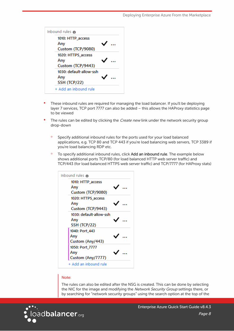
• If a new NSG is created, the following inbound rules are included by default:
Enterprise Azure Quick Start Guide v8.4.3
Page 7
Deploying Enterprise Azure From the Marketplace
• These inbound rules are required for managing the load balancer. If you'll be deploying layer 7 services, TCP port 7777 can also be added – this allows the HAProxy statistics page to be viewed
• The rules can be edited by clicking the Create new link under the network security group drop-down
◦ Specify additional inbound rules for the ports used for your load balanced applications, e.g. TCP 80 and TCP 443 if you're load balancing web servers, TCP 3389 ifyou're load balancing RDP etc.
◦ To specify additional inbound rules, click Add an inbound rule. The example below shows additional ports TCP/80 (for load balanced HTTP web server traffic) and TCP/443 (for load balanced HTTPS web server traffic) and TCP/7777 (for HAProxy stats)
Note:
The rules can also be edited after the NSG is created. This can be done by selecting the NIC for the image and modifying the Network Security Group settings there, or by searching for “network security groups” using the search option at the top of the
Enterprise Azure Quick Start Guide v8.4.3
Page 8

Deploying Enterprise Azure From the Marketplace
page to list all groups, then selecting and modifying the relevant group.
◦ Once the required rules have been defined, click OK
Note:
Microsoft recommends that where possible Network Security Groups are associated with subnets rather than individual interfaces since this simplifies management. To make the association at the subnet level, edit the security group, associate the group with the relevant subnet then delete the association with the NIC.
3. Click Next : Management >
Configure Management Settings
4. Configure the Management Settings according to your requirements
5. Click Next : Advanced >
Configure Advanced Settings
1. Configure the Advanced Settings according to your requirements
Enterprise Azure Quick Start Guide v8.4.3
Page 9

Deploying Enterprise Azure From the Marketplace
2. Click Next : Tags >
Configure Tags
1. Configure Tags according to your requirements
2. Click Next : Review & Create >
Enterprise Azure Quick Start Guide v8.4.3
Page 10
Deploying Enterprise Azure From the Marketplace
Review & Create
1. Review all details, terms and settings and if you're happy to proceed click Create
2. The load balancer will now be deployed
Enable IP Forwarding (If Required)
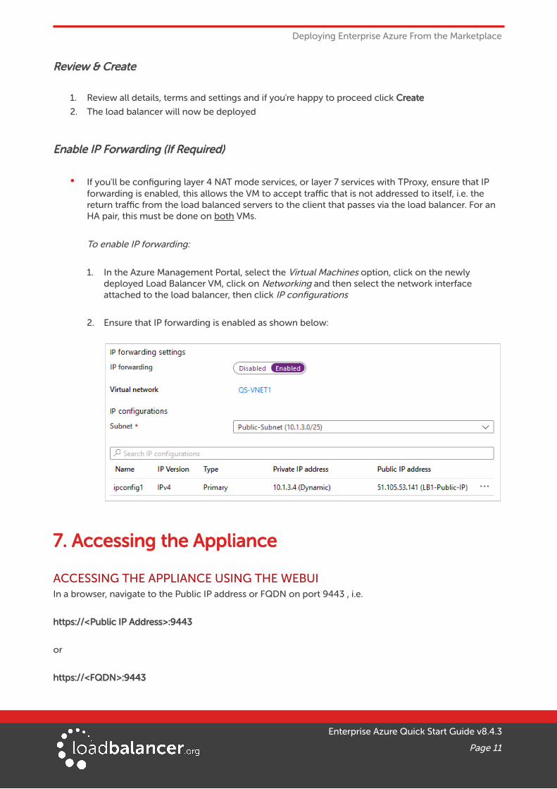
• If you'll be configuring layer 4 NAT mode services, or layer 7 services with TProxy, ensure that IP forwarding is enabled, this allows the VM to accept traffic that is not addressed to itself, i.e. the return traffic from the load balanced servers to the client that passes via the load balancer. For an HA pair, this must be done on both VMs.
To enable IP forwarding:
1. In the Azure Management Portal, select the Virtual Machines option, click on the newly deployed Load Balancer VM, click on Networking and then select the network interface attached to the load balancer, then click IP configurations
2. Ensure that IP forwarding is enabled as shown below:
7. Accessing the Appliance
ACCESSING THE APPLIANCE USING THE WEBUIIn a browser, navigate to the Public IP address or FQDN on port 9443 , i.e.
https://<Public IP Address>:9443
or
https://<FQDN>:9443
Enterprise Azure Quick Start Guide v8.4.3
Page 11

Accessing the Appliance
Note:
To configure an FQDN in Azure under the Resource Manager model please refer to this link.
You'll receive a warning about the certificate as it's a self signed cert not related to an Internet based CA. Confirm you want to continue and a login prompt will be displayed. Use the following default credentials:
Username: loadbalancer
Password: loadbalancer
Note:
To change the password for the 'loadbalancer' account, use the WebUI option: Maintenance > Passwords.
Once logged in, the WebUI is displayed:
Enterprise Azure Quick Start Guide v8.4.3
Page 12

Accessing the Appliance
WEBUI MENU OPTIONSThe main menu options are as follows:
System Overview – Displays a graphical summary of all VIPs, RIPS and key appliance statistics
Local Configuration – Configure local host settings such as DNS, Date & Time etc.
Cluster Configuration – configure load balanced services such as VIPs & RIPs
Maintenance – Perform maintenance tasks such as service restarts and taking backups
View Configuration – Display the saved appliance configuration settings
Reports – View various appliance reports & graphs
Logs – View various appliance logs
Support – Create a support download & contact the support team
APPLIANCE SECURITYTo control how the appliance is accessed and which features are enabled, 3 security modes are provided:
• Secure – this is the default mode. In this mode:
◦ the WebUI is accessible on HTTPS port 9443. If you attempt to access the WebUI on HTTP port 9080 you will be redirected to HTTPS port 9443
◦ access to the “Execute Shell Command” menu option is disabled
◦ the ability to edit the firewall script & the lockdown wizard is disabled
◦ 'root' user console & SSH password access are disabled
• Custom – In this mode, the security options can be configured to suit your requirements
• Secure – Permanent – this mode is the same as Secure, but the change is irreversible
IMPORTANT:
Only set the security mode to Secure – Permanent if you are 100% sure this is what you want!
To configure the Security Mode:
1. Using the WebUI, navigate to: Local Configuration > Security
2. Select the required Appliance Security Mode
3. If Custom is selected, configure the other options to suit your requirements
4. Click Update
Note:
For full details of all options, please refer to the Administration Manual and search for “ApplianceSecurity Options”.
Default Password
We strongly recommend that the default ‘loadbalancer’ WebUI account password is changed as soon as the appliance is deployed. This can be changed using the WebUI menu option: Maintenance > Passwords.
CHECKING FOR UPDATESOnce you have access to the WebUI, we recommend that you use the online update feature to ensure that
Enterprise Azure Quick Start Guide v8.4.3
Page 13

Accessing the Appliance
you're running the very latest version of the appliance. To check for updates, use the WebUI option: Maintenance > Software Update and click the Online Update button. If updates are available, you'll be presented with a list of changes that are included in the update. To start the update, click the second Online Update button at the bottom of the screen. Updates are incremental, so repeat the process until you're informed that no more updates are available.
APPLIANCE LICENSINGIf you've deployed the BYOL version of the appliance, by default it runs as a 30 day trial and is completely unrestricted during this time. After 30 days, the appliance continues to work but it's no longer possible to make changes to the configuration. When a license is purchased, you'll be provided with a license key file by our sales team. This must then be installed on your appliance. To install the license, use the WebUI option: Local Configuration > License Key to browse to and select the license file provided. Once selected, click Install License Key to apply the license. We recommend that you should check for updates before applying the license key.
ENTERPRISE AZURE NON-STANDARD WEBUI MENU OPTIONSEnterprise Azure has some differences to the standard hardware/virtual product range due to the way the Microsoft Azure environment works. The menu options that work differently are detailed below. For all others please refer to our main Administration Manual.
1) Local Configuration > Network Interface Configuration
This menu option works in a very similar way to the standard product range, although please note the following:
• On initial deployment, a single IP private address is allocated (either static or dynamic depending on the chosen setting)
• Additional addresses can be added as shown (10.1.6.10/24) – this is required when you require multiple VIPs on different IP addresses
• To add an additional IP address, enter the new address below the existing address as shown in the example above, then click Configure Interfaces
IMPORTANT:
If an IP address is added, you'll also need to add the same IP address to the Network Interface on the load balancer VM via the Azure portal. If this is not done, Azure will not be aware of the new address.
Enterprise Azure Quick Start Guide v8.4.3
Page 14

Accessing the Appliance
IMPORTANT:
If the IP address allocated to the VM on initial deployment (normally the first in the list) is changed, make sure that you add the same address to the VMs in Azure. If this is not done, you'llloose connectivity to the VM.
ACCESSING THE APPLIANCE USING SSHWhen the appliance is deployed, Authentication type must be set to either SSH Public key or Password. When set to SSH Public Key, a key pair must be manually generated outside of the Azure environment using tools such as ssh-keygen under Linux and PuttyGen under Windows. Once the key pair is generated, the public key must be copied into the SSH public key field at VM deployment, and the private key is then used on the SSH client machine to access the VM.
GENERATING SSH KEYSThe steps below show how to generate SSH key pairs using Linux and Windows.
Using Linux
Generate a keypair using ssh-keygen
All Distros:
# ssh-keygen -q -t rsa -b 2048 -f <output filename>
e.g.
# ssh-keygen -q -t rsa -b 2048 -f AzureKeys
When prompted, enter a pass-phrase, or leave empty for no passphrase:
Enter passphrase (empty for no passphrase):
Enter same passphrase again:
2 files are created:
• AzureKeys – this is the Private Key file and is used on the SSH client machine
• AzureKeys.pub – this is the Public Key file, the contents are copied into the SSH public key field when the VM is deployed
Using Windows
STEP 1 – Install PuTTY
1. Download PuTTY from here2. Run the installer
STEP 2 – Use PuTTYgen to generate a Public/Private key pair
Enterprise Azure Quick Start Guide v8.4.3
Page 15

Accessing the Appliance
1. Browse to the PuTTY program folder and run PuTTYgen
2. Click the Generate button
3. As directed, move the mouse around to create random keys
4. Once generated, click the Save public key and Save private key buttons to save the keys
ACCESSING THE APPLIANCE FROM LINUXStart SSH specifying the private key file and login as the user defined when deploying the VM, e.g.
Using the IP address:
# ssh -i /root/AzureKeys [email protected]
Or using the fqdn:
# ssh -i /root/AzureKeys lbuser@fqdn
Note:
To configure an FQDN in Azure under the Resource Manager model please refer to this link.
ACCESSING THE APPLIANCE FROM WINDOWS USING PUTTY
1. Run PuTTY
2. Expand the SSH section and select Auth as shown below
Enterprise Azure Quick Start Guide v8.4.3
Page 16

Accessing the Appliance
3. Click Browse and select the private key created earlier
4. Click Open to start the SSH session
5. Login using the username specified when deploying the instance, no password will be required
Note:
To enable full root access, the following command can be used once logged in to the appliancevia SSH: $ sudo su
Enterprise Azure Quick Start Guide v8.4.3
Page 17

Configuration Examples
8. Configuration ExamplesThe following sections provide a number of examples to help illustrate how the load balancer can be deployed.
DEPLOYMENT NOTES
High Availability
• We recommend that 2 appliance's are deployed as an HA pair to avoid introducing a single point offailure. For Azure, we also recommend that you configure your HA pair first before setting up your load balanced services – this is the simplest approach. Please refer to page 33 for an example using HA.
• If you do configure a single appliance first (as in the examples below) and later want to add a slave appliance and create an HA pair, follow these steps:
Note:
The following procedure assumes that your existing appliance will be the master of the HA pair.
1. Deploy an additional Loadbalancer.org VM to be the slave, make sure it's in the SAME Availability Set.
2. On the master appliance, using the WebUI option: Cluster Configuration > Floating IPs remove the floating IPs that were automatically configured for each VIP, then using the WebUI option: Local Configuration > Network Interface Configuration add the same addresses to the network interface instead. This will ensure that these IPs appear in the drop-downs used to setup the VIP(s) when in HA mode as illustrated in step 7 on page 42.
3. On the slave appliance, using the WebUI option: Local Configuration > Network Interface Configuration add corresponding IPs for each VIP. This will ensure that these IPs appear in the drop-downs used to setup the VIP(s) when in HA mode.
4. Follow Step 2 to 6 starting on page 33.
5. Using the WebUI on the master appliance, ensure that the Virtual Service IP address & Slave IP Address fields are set correctly for each VIP. As explained on page 3, these drop-downs are used to specify the IP address used for the VIP when active on the master and when active on the slave.
6. Follow Step 7 on page 41.
7. Follow Step 10 on page 43.
8. Follow Step 11 on page 44.
1 – LOAD BALANCING WEB SERVERS – 1 SUBNET, LAYER 7This is a simple, single appliance, layer 7 example using one subnet for both the load balancer and the webservers.
a) Setting up Azure
1. Deploy the load balancer instance as described earlier in the section starting on page 5
2. Deploy the web server VMs into the same VNet & subnet as the load balancer
3. Ensure that the Network Security Group includes TCP ports 80 & 443
4. Ensure that you add the private IP address to be used for the VIP to the VMs NIC using the Azure Portal, otherwise Azure will not be aware of this address
Enterprise Azure Quick Start Guide v8.4.3
Page 18

Configuration Examples
b) Setting up the Virtual Service
1. Using the WebUI, navigate to: Cluster Configuration > Layer 7 – Virtual Services and click Add a New Virtual Service
2. Enter the following details:
3. Enter an appropriate label for the VIP, e.g. Web-Cluster1
4. Set the Virtual Service IP Address field to an appropriate value, e.g. 10.1.6.40
Note:
When you click Update , a corresponding floating IP matching the IP address assigned to the Virtual Service is automatically created on the appliance and can be viewed using the WebUI option: Cluster Configuration > Floating IPs.
If you plan to configure an HA pair, we recommend that you first add the IP address to be used for the VIP to the load balancer using the WebUI option: Local Configuration > Network Interface Configuration before creating the virtual Service. This will ensure that these IPs appearin the drop-downs that are used to setup VIP(s) when in HA mode as explained on page 18.
Whichever way the IP address is added, you’ll also need to assign the same IP address to the load balancer’s network interface using the Azure Portal. If this is not done, Azure will not be aware of the new address.
5. Set the Virtual Service Ports field to 80,443
6. Leave Layer 7 Protocol set to TCP Mode
7. Click Update
c) Setting up the Real Servers
1. Using the WebUI, navigate to: Cluster Configuration > Layer 7 – Real Servers and click Add a new Real Server next to the newly created VIP
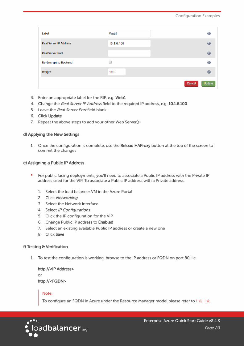
2. Enter the following details:
Enterprise Azure Quick Start Guide v8.4.3
Page 19
Configuration Examples
3. Enter an appropriate label for the RIP, e.g. Web1
4. Change the Real Server IP Address field to the required IP address, e.g. 10.1.6.100
5. Leave the Real Server Port field blank
6. Click Update
7. Repeat the above steps to add your other Web Server(s)
d) Applying the New Settings
1. Once the configuration is complete, use the Reload HAProxy button at the top of the screen to commit the changes
e) Assigning a Public IP Address
• For public facing deployments, you'll need to associate a Public IP address with the Private IP address used for the VIP. To associate a Public IP address with a Private address:
1. Select the load balancer VM in the Azure Portal
2. Click Networking
3. Select the Network Interface
4. Select IP Configurations
5. Click the IP configuration for the VIP
6. Change Public IP address to Enabled
7. Select an existing available Public IP address or create a new one
8. Click Save
f) Testing & Verification
1. To test the configuration is working, browse to the IP address or FQDN on port 80, i.e.
http://<IP Address>
or
http://<FQDN>
Note:
To configure an FQDN in Azure under the Resource Manager model please refer to this link.
Enterprise Azure Quick Start Guide v8.4.3
Page 20

Configuration Examples
2 – LOAD BALANCING WEB SERVERS – 1 SUBNET, LAYER 7, SSL TERMINATIONThis is similar to the first example with the addition of SSL termination on the load balancer. We generally recommend that SSL should be terminated on the backend servers rather than the load balancer for scalability reasons, although in some cases terminating on the load balancer may be preferred. As with example 1, a single appliance is used.
a) Setting up Azure
1. Deploy the load balancer instance as described earlier in the section starting on page 5
2. Deploy the web server VMs into the same VNet & subnet as the load balancer
3. Ensure that the Network Security Group includes TCP ports 80 & 443
4. Ensure that you add the private IP address to be used for the VIP to the VMs NIC using the Azure Portal, otherwise Azure will not be aware of this address
b) Setting up the Virtual Service
1. Using the WebUI, navigate to: Cluster Configuration > Layer 7 – Virtual Services and click Add a New Virtual Service
2. Enter the following details:
3. Enter an appropriate label for the VIP, e.g. Web-Cluster1
4. Set the Virtual Service IP Address field to an appropriate value, e.g. 10.1.6.40
Note:
When you click Update, a corresponding floating IP matching the IP address assigned to the Virtual Service is automatically created on the appliance and can be viewed using the WebUI option: Cluster Configuration > Floating IPs.
If you plan to configure an HA pair, we recommend that you first add the IP address to be used for the VIP to the load balancer using the WebUI option: Local Configuration > Network Interface Configuration before creating the virtual Service. This will ensure that these IPs appearin the drop-downs that are used to setup VIP(s) when in HA mode as explained on page 18.
Whichever way the IP address is added, you’ll also need to assign the same IP address to the load balancer’s network interface using the Azure Portal. If this is not done, Azure will not be aware of the new address.
Enterprise Azure Quick Start Guide v8.4.3
Page 21

Configuration Examples
5. Set the Virtual Service Ports field to 80
6. Leave Layer 7 Protocol set to HTTP Mode
7. Click Update
c) Setting up the Real Servers
1. Using the WebUI, navigate to: Cluster Configuration > Layer 7 – Real Servers and click Add a new Real Server next to the newly created VIP
2. Enter the following details:
3. Enter an appropriate label for the RIP, e.g. Web1
4. Change the Real Server IP Address field to the required IP address, e.g. 10.1.6.100
5. Click Update
6. Repeat the above steps to add your other Web Server(s)
d) Upload an SSL Certificate
1. Using the WebUI, navigate to SSL Termination and click Add a new SSL Certificate
2. Select Upload prepared PEM/PFX file
3. Enter an appropriate label (name) for the certificate, e.g. Cert1
4. Browse to and select the relevant certificate file
5. for PFX files, enter the PFX File Password
6. Click Add Certificate
Note:
You can also create a CSR on the load balancer. If this is required, select the Create A New SSL Certificate (CSR) option instead of Upload prepared PEM/PFX file in step 2 above. For additional information please refer to the Administration Manual and search for “Generating a CSR on the Load Balancer”.
e) Configuring SSL Termination
1. Using the WebUI, navigate to: Cluster Configuration > SSL Termination and click Add a New Virtual Service
Enterprise Azure Quick Start Guide v8.4.3
Page 22

Configuration Examples
2. Set the Associated Virtual Service drop-down to the VIP created in step (b) above (the Label field will be auto-populated)
3. Leave the SSL Operation Mode set to High Security
4. Select the SSL Certificate uploaded in step (d) above
5. Click Update
Note:
For an HA pair, there are 2 additional drop-downs – one for the IP address of the STunnel VIP when it's active on the Master, the other for the IP address of the STunnel VIP when active on the Slave. Also, the Backend Virtual Service Port field is included as illustrated in the screenshot below:
For more details on setting up an HA pair, please refer to page 32.
f) Applying the New Settings
• Once the configuration is complete:
1. use the Reload HAProxy button at the top of the screen to commit the changes
2. use the Restart STunnel button at the top of the screen to commit the changes
g) Assigning a Public IP Address
Enterprise Azure Quick Start Guide v8.4.3
Page 23

Configuration Examples
• For public facing deployments, you'll need to associate a Public IP address with the Private IP address used for the VIP. To associate a Public IP address with a Private address:
1. Select the load balancer VM in the Azure Portal
2. Click Networking
3. Select the Network Interface
4. Select IP Configurations
5. Click the IP configuration for the VIP
6. Change Public IP address to Enabled
7. Select an existing available Public IP address or create a new one
8. Click Save
h) Testing & Verification
• To test the configuration is working, browse to the public IP address or FQDN on HTTP port 80 and HTTPS port 443, i.e.
http://<Public IP Address> and https://<Public IP Address>
or
http://<FQDN> and https://<Public IP Address>
Note:
To configure an FQDN in Azure under the Resource Manager model please refer to this link.
3 – LOAD BALANCING WEB SERVERS – 2 SUBNETS, LAYER 4 NAT MODEThis example uses 2 subnets – one public subnet for the load balancer and one private subnet for the web servers. The load balancer has a single network interface located in the first subnet. Routing rules for the second private subnet must be changed so that return traffic passes back via the load balancer. This is achieved by creating a custom routing table with the required rules, then associating this with the private subnet – this can now be done directly in the portal (step c below), previously PowerShell had to be used.
Note:
This configuration is currently not supported in HA mode. In this mode, the custom routing rules would need to be dynamically modified to route via the Slave appliance rather than the Master if a failover occurs which is not currently supported.
a) Setting up Azure
1) Deploy VM’s & Configure Network Security Groups:
1. Deploy the load balancer instance into the first (public) subnet as described in the section starting on page 5
2. Deploy your required web server VMs into the second (private) subnet
3. Configure Network Security Groups to permit the required traffic flows. Configure the following rules for the 2 subnets (assuming a public facing deployment):
Enterprise Azure Quick Start Guide v8.4.3
Page 24
Configuration Examples
Load Balancer (Public) Subnet:
Inbound rule – from 0.0.0.0/0 to port 80
Outbound rule – from 0.0.0.0/0 to private subnet, port 80
Web Server (Private) Subnet:
Inbound rule – from 0.0.0.0/0 to port 80
4. Ensure that you add the private IP address to be used for the VIP to the VMs NIC using the Azure Portal, otherwise Azure will not be aware of this address
2) Configure a Custom Routing Table
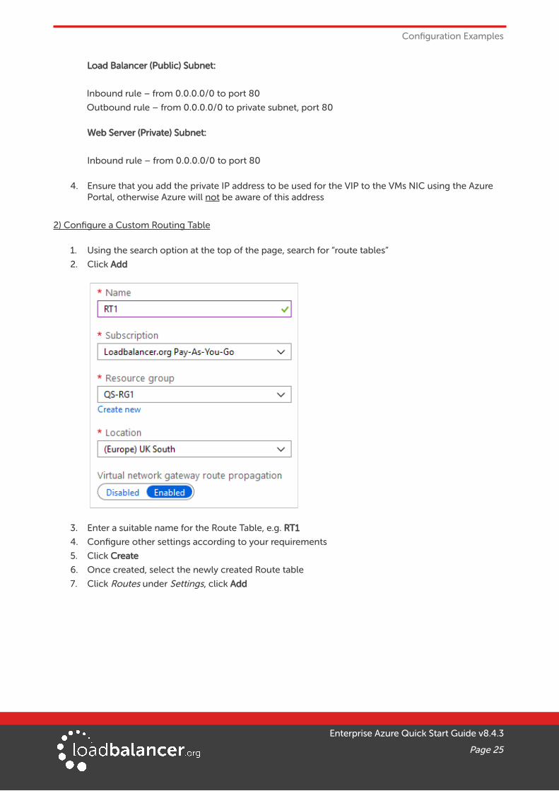
1. Using the search option at the top of the page, search for “route tables”
2. Click Add
3. Enter a suitable name for the Route Table, e.g. RT1
4. Configure other settings according to your requirements
5. Click Create
6. Once created, select the newly created Route table
7. Click Routes under Settings, click Add
Enterprise Azure Quick Start Guide v8.4.3
Page 25

Configuration Examples
8. Enter a suitable name for the route, e.g. R1
9. Set the Address prefix to 0.0.0.0/0 (i.e. the default route)
10. Set the next hop type to Virtual appliance
11. Set the next hop address to the IP address of the load balancer in the public subnet, e.g. 10.1.6.5
12. Click OK
Note:
As mentioned in the note in the above screen shot, IP forwarding must be enabled for the load balancer VM. This is covered below in section c).
13. Click Subnets under Settings
14. Click Associate
15. Select the relevant VNet and the Private Subnet
16. Click OK
3) Enable IP Forwarding for the Load balancer VM:
1. In the Azure Portal main menu, select Virtual Machines
2. Select the Load balancer VM and click Networking under Settings
3. Click the Network Interface for the VM
4. Click IP Configurations
5. Ensure that IP forwarding is enabled as shown below
Enterprise Azure Quick Start Guide v8.4.3
Page 26

Configuration Examples
6. Click Save
b) Configure the Virtual Service on the Load Balancer
1. Using the WebUI, navigate to: Cluster Configuration > Layer 4 – Virtual Services and click Add a New Virtual Service
2. Enter the following details:
3. Enter an appropriate label for the VIP, e.g. Web-Cluster1
4. Set the Virtual Service IP Address field to an appropriate value, e.g. 10.1.6.40
Note:
When you click Update, a corresponding floating IP matching the IP address assigned to the Virtual Service is automatically created on the appliance and can be viewed using the WebUI option: Cluster Configuration > Floating IPs.
If you plan to configure an HA pair, we recommend that you first add the IP address to be used for the VIP to the load balancer using the WebUI option: Local Configuration > Network Interface Configuration before creating the virtual Service. This will ensure that these IPs appearin the drop-downs that are used to setup VIP(s) when in HA mode as explained on page 18.
Whichever way the IP address is added, you’ll also need to assign the same IP address to the load balancer’s network interface using the Azure Portal. If this is not done, Azure will not be aware of the new address.
5. Set the Virtual Service Ports field to 80
6. Leave Protocol set to TCP
7. Ensure Forwarding Method is set to NAT
8. Click Update
c) Setting up the Real Servers
Enterprise Azure Quick Start Guide v8.4.3
Page 27

Configuration Examples
1. Using the WebUI, navigate to: Cluster Configuration > Layer 4 – Real Servers and click Add a new Real Server next to the newly created VIP
2. Enter the following details:
3. Enter an appropriate label for the RIP, e.g. Web1
4. Change the Real Server IP Address field to the required IP address, e.g. 10.1.8.100
5. Set the Real Server Port field to 80
6. Click Update
7. Repeat the above steps to add your other Web Server(s)
Note:
If you want your Real Severs to be able to access the outside world, i.e. the Internet in a public facing deployment, outbound requests passing via the load balancer must be NAT’d so that the source IP becomes the load balancer’s own external address. This can be configured using the WebUI menu option: Cluster Configuration > Layer 4 Advanced Configuration and setting the Auto-NAT drop-down to eth0.
d) Assigning a Public IP Address
• For public facing deployments, you'll need to associate a Public IP address with the Private IP address used for the VIP. To associate a Public IP address with a Private address:
1. Select the load balancer VM in the Azure Portal
2. Click Networking
3. Select the Network Interface
4. Select IP Configurations
5. Click the IP configuration for the VIP
6. Change Public IP address to Enabled
7. Select an existing available Public IP address or create a new one
8. Click Save
e) Testing & Verification
• To test the configuration is working, browse to the public IP address or FQDN on HTTP port 80, i.e.
Enterprise Azure Quick Start Guide v8.4.3
Page 28

Configuration Examples
http://<Public IP Address>
or
http://<FQDN>
Note:
To configure an FQDN in Azure under the Resource Manager model please refer to this link.
4 – LOAD BALANCING WEB SERVERS – 2 SUBNETS, LAYER 7 SNAT MODE WITH TPROXYThis example is the same as the previous example with regard to network layout. It uses 2 subnets – one public subnet for the load balancer and one private subnet for the web servers. The load balancer has a single network interface located in the first subnet. Routing rules for the second private subnet must be changed so that return traffic passes back via the load balancer. This is achieved by creating a custom routing table with the required rules, then associating this with the private subnet.
In addition, Layer 7 transparency is enabled on the load balancer to ensure that the source IP address of packets reaching the web servers is the source IP of the clients and not the IP address of the load balancer.
Note:
This configuration is currently not supported in HA mode. In this mode, the custom routing rules would need to be dynamically modified to route via the Slave appliance rather than the Master if a failover occurs which is not currently supported.
a) Setting up Azure
Follow steps 1 to 3 in the “Setting up Azure” section of example 3 on page 24.
b) Enable Transparent Proxy (TProxy) on the Load Balancer
Enabling TProxy ensures that the Real Servers behind the load balancer see the client source IP address in requests.
1. Using the WebUI, navigate to: Cluster Configuration > Layer 7 – Advanced Configuration
2. Ensure that Transparent Proxy is enabled as shown above.
3. Click Update
c) Configure the Virtual Service on the Load Balancer
1. Using the WebUI, navigate to: Cluster Configuration > Layer 7 – Virtual Services and click Add a New Virtual Service
2. Enter the following details:
Enterprise Azure Quick Start Guide v8.4.3
Page 29

Configuration Examples
3. Enter an appropriate label for the VIP, e.g. Web-Cluster1
4. Set the Virtual Service IP Address field to an appropriate value, e.g. 10.1.6.40
Note:
When you click Update, a corresponding floating IP matching the IP address assigned to the Virtual Service is automatically created on the appliance and can be viewed using the WebUI option: Cluster Configuration > Floating IPs.
If you plan to configure an HA pair, we recommend that you first add the IP address to be used for the VIP to the load balancer using the WebUI option: Local Configuration > Network Interface Configuration before creating the virtual Service. This will ensure that these IPs appearin the drop-downs that are used to setup VIP(s) when in HA mode as explained on page 18.
Whichever way the IP address is added, you’ll also need to assign the same IP address to the load balancer’s network interface using the Azure Portal. If this is not done, Azure will not be aware of the new address.
5. Set the Virtual Service Ports field to 80
6. Leave Protocol set to HTTP Mode
7. Click Update
d) Setting up the Real Servers
1. Using the WebUI, navigate to: Cluster Configuration > Layer 7 – Real Servers and click Add a new Real Server next to the newly created VIP
2. Enter the following details:
Enterprise Azure Quick Start Guide v8.4.3
Page 30

Configuration Examples
3. Enter an appropriate label for the RIP, e.g. Web1
4. Change the Real Server IP Address field to the required IP address, e.g. 10.1.8.100
5. Set the Real Server Port field to 80
6. Click Update
7. Repeat the above steps to add your other Web Server(s)
Note:
If you want your Real Severs to be able to access the outside world, i.e. the Internet in a public facing deployment, outbound requests passing via the load balancer must be NAT’d so that the source IP becomes the load balancer’s own external address. This can be configured using the WebUI menu option: Cluster Configuration > Layer 4 Advanced Configuration and setting the Auto-NAT drop-down to eth0.
e) Assigning a Public IP Address
• For public facing deployments, you'll need to associate a Public IP address with the Private IP address used for the VIP. To associate a Public IP address with a Private address:
1. Select the load balancer VM in the Azure Portal
2. Click Networking
3. Select the Network Interface
4. Select IP Configurations
5. Click the IP configuration for the VIP
6. Change Public IP address to Enabled
7. Select an existing available Public IP address or create a new one
8. Click Save
f) Testing & Verification
• To test the configuration is working, browse to the public IP address or FQDN on HTTP port 80, i.e.
http://<Public IP Address>
or
http://<FQDN>
Note:
To configure an FQDN in Azure under the Resource Manager model please refer to this link.
Enterprise Azure Quick Start Guide v8.4.3
Page 31

Configuring High Availability using two instances (Master & Slave)
9. Configuring High Availability using two instances (Master & Slave)
Enterprise Azure supports HA by using two Loadbalancer.org VMs configured as a clustered pair in combination with an Azure load balancer as shown in the diagram below.
Enterprise Azure Quick Start Guide v8.4.3
Page 32
Web 1
Health Probe - checks for a valid HTTP response on TCP port 6694, load balancing rules then direct traffic to that VM (normally the master)
Configuration Replication
Availability Set
Azure LB NAT rules – can beUsed to enable access toadmin ports on both LB's
(TCP 22, 7777, 9080, 9443)
HeartbeatUDP 6694
Azure LB
MASTER(normallyactive)
Web 1 Web 1 RDP 1 RDP 2
VIP1 VIP2
SLAVE(normally
passive)
VIP1 VIP2
1.2.3.4 5.6.7.8 1.2.3.5
BackendPool 1
BackendPool 2
IP 1 : 80,443 IP 2 : 3389
80 443 3389
5.6.7.9
Load balancing rules map from a port on the Azure load balancer to a port on the back-end pool
80,443 80,4433389 3389
TCP6694
TCP6694

Configuring High Availability using two instances (Master & Slave)
• LB1 and LB2 are configured as an HA pair. In this mode, one device is active (typically the Master appliance) and the other is passive (typically the Slave appliance).
• For an Azure HA pair, a different approach to our hardware/virtual product is used to handle VIP failover. In our standard product, the same IP is brought up on the passive device (normally the Slave) should the active device (normally the Master) fail.
• When creating a VIP on an Azure HA pair, 2 private IPs must be specified – one for the VIP when it'sactive on the Master and one for the VIP when it's active on the Slave. An Azure load balancer is then used to forward traffic to the active appliance. This approach is used to minimize the time taken to failover between devices.
• The private IPs for the VIP on the Master & Slave are selected using drop-downs within the VIP configuration screen. These drop-downs are only displayed once the pair is configured. They are populated with the IPs that are assigned to the network interface using the WebUI option: Local Configuration > Network Interface Configuration.
• The probe service on TCP port 6694 is up on the active appliance (LB1) and down on the passive appliance (normally LB2), The active appliance responds with 200 OK.
• The Azure load balancer probes port 6694 on LB1 and LB2 and then forwards traffic to the active load balancer appliance (normally LB1).
• If the Master appliance fails for any reason, the passive appliance will detect this, become active and bring up the probe service on port 6694. In turn, the Azure load balancer detects this and will then forward traffic to the Slave device (LB2).
• If your configuration includes VIPs with multiple ports or if you have multiple VIPs you'll need to setup multiple Load balancing rules to map from the Azure load balancer's Frontend IP to the appropriate Backend Pool and appropriate port. Also, you may need to setup multiple Frontend IP Configurations & Backend Pools depending on whether your VIPs share the same IP or have unique IP addresses, and whether the load balanced servers are common between VIPs or unique. The same Health-probe should be used for all Load balancing rules. This is illustrated in the diagram on page 32.
EXAMPLE HA CONFIGURATION – LOAD BALANCING WEB SERVERS – 1 SUBNET, LAYER 7
Step 1 – Deploy 2 x Loadbalancer.org VMs – one to be the Master, the other to be the Slave
1. Please refer to the steps starting on page 5. Ensure that both load balancer VMs are in the SAME Availability Set
Step 2 – Verify Network Security Group Settings
1. Ensure that your Network Security Group(s) permit the following communication between the 2 VMs:
• TCP port 22 (SSH)
• UDP port 6694 (heartbeat)
• ICMP Ping
Note:
These requirements are covered by default within the same Virtual Network. Please refer to this link for more information on default rules.
Enterprise Azure Quick Start Guide v8.4.3
Page 33

Configuring High Availability using two instances (Master & Slave)
2. Ensure that your Network Security Group(s) permit the following inbound communication from the Azure load balancer to both VMs:
• TCP port 6694 (Azure load balancer health probe)
Note:
This requirement is covered by default within the same Virtual Network. Please refer to this link for more information on default rules.
Step 3 – Add the IP Address to be used for the VIP to the Master & Slave using the Azure Portal
1. In the Azure Portal select Virtual Machines
2. Select the Master VM
3. Select Networking, then click the Network Interface
4. Select IP Configurations
5. Click Add
• Enter a suitable name for the IP address, e.g. VIP1
• Set Private IP address Allocation to Static
• Enter an appropriate IP address (this must tally with the address to be used for your VIP on the Loadbalancer.org appliance), e.g. 10.1.6.10
• Click OK
6. Now repeat steps 1-6 on the Slave VM for the VIP using a corresponding (but different) IP address, e.g. 10.1.6.11
Enterprise Azure Quick Start Guide v8.4.3
Page 34

Configuring High Availability using two instances (Master & Slave)
Step 4 – Add the IP Address to be used for the VIP to the Master & Slave using the Appliance WebUI
Master appliance
◦ On the Master, navigate to the WebUI option: Local Configuration > Network Interface Configuration
◦ Add the IP you intend to use for the VIP, use CIDR notation, e.g. 10.1.6.10/24
Slave appliance
◦ On the Slave, navigate to the WebUI option: Local Configuration > Network Interface Configuration
◦ Add the IP you intend to use for the VIP, use CIDR notation, e.g. 10.1.6.11/24
Step 5 – Add & Configure the Azure Load Balancer
1. First, add the Azure Load Balancer
• In the Azure Portal select Load balancers
• Click Add
• Configure the Subscription & Resource group settings according to your requirements
• Enter a suitable name for the instance, e.g. AzureLB
• Select the required Region
• If deploying within a private network set Type to Internal, if it's public facing select Public
Enterprise Azure Quick Start Guide v8.4.3
Page 35

Configuring High Availability using two instances (Master & Slave)
• Set SKU to Basic
• Configure the Public IP address settings (for external deployments) / Virtual Network settings (for internal deployments) according to your requirements
Note:
Once the Azure Load balancer is created, the IP configuration can be modified using the Frontend IP Configuration in the Load balancer menu.
• Click Next : Tags >
• Configure the Tags according to your requirements
• Click Next : Review + Create >
• Review the settings and click Create
2. Next, create the Backend Pool(s)
• In the menu for the load balancer, click Backend pools
• Click Add
• Enter an appropriate name, e.g. BP1
• Select the required IP version, e.g. IPv4
• Select the Availability set that contains the load balancer VMs, e.g. AS1
• Ensure that both load balancer VMs are selected as shown in the example above (LB-Master &
Enterprise Azure Quick Start Guide v8.4.3
Page 36

Configuring High Availability using two instances (Master & Slave)
LB-Slave), and that the IP addresses selected correspond to the VIP on the Master & Slave (10.1.6.10 & 10.1.6.11)
• Click OK
Note:
If you have multiple VIPs on different IPs you'll need to setup a Backend Pool for each of these. This is illustrated in the diagram on page 32.
3. Next, create a Health Probe
• In the menu for the Load balancer, click Health-probes
• Click Add
• Enter an appropriate name, e.g. LB-Probe
• Set Protocol to HTTP
Note:
Setting Protocol to HTTP will configure the Azure load balancer to look for a 200 OK response from each Loadbalancer.org VM.
• Set Port to 6694
• Leave the remaining settings at their default values
• Click OK
Enterprise Azure Quick Start Guide v8.4.3
Page 37

Configuring High Availability using two instances (Master & Slave)
Note:
The same Health probe should be used across all Load balancing rules.
4. Next, configure the Load Balancing Rule
• In the menu for the Load balancer, click Load balancing rules
• Click Add
• Enter an appropriate name, e.g. LB-Rule1
• Select the required IP version, e.g. IPv4
• Set the Protocol to TCP
• Set the Port to the required value, e.g. 80
• Set the Backend port to the required value, e.g. 80
• Select the Backend pool created previously
Enterprise Azure Quick Start Guide v8.4.3
Page 38

Configuring High Availability using two instances (Master & Slave)
• Select the Health Probe created previously
• Leave Session persistence set to None – session persistence is not required since the Azure Load balancer will simply send all traffic to the working Loadbalancer.org appliance, i.e the appliance that is responding with a 200 OK to the HTTP probe on TCP port 6694
• Click OK
Note:
If your configuration includes other ports (e.g. HTTPS port 443) or if you have multiple VIPs you'll need to setup multiple Load balancing rules to map from the Azure load balancers Frontend IP to the appropriate Backend Pool and appropriate port. Also, you may need to setup multiple Frontend IP Configurations & Backend Pools depending on whether your VIPs share the same IP or have unique IP addresses, and whether the load balanced servers are common between VIPs or unique. The same Health-probe should be used for all Load balancing rules. This is illustrated in the diagram on page 32.
5. Next, configure any required Inbound NAT Rules to enable VM access via the Azure Load balancer
Note:
This step is optional, you may have alternative ways of accessing & managing your VMs. Theexample below shows how to setup a rule to allow SSH access (TCP port 22) to the Master Loadbalancer.org VM via the Azure load balancer IP on TCP port 122.
• In the menu for the Load balancer, click Inbound NAT rules
• Click Add
Screenshot continued.....
Enterprise Azure Quick Start Guide v8.4.3
Page 39

Configuring High Availability using two instances (Master & Slave)
• Enter an appropriate name, e.g. NAT-Rule1
• The Frontend IP address is the address of the Azure load balancer
• Set Service to Custom
• Set Protocol to TCP
• Set Port to 122
• Set Target Virtual Machine to the Master Loadbalancer.org appliance, e.g. LB1
• Set Network IP Configuration to the Interface on the Master Loadbalancer.org appliance
• Set Port Mapping to Custom
• Set Target port to 22
• Click OK
Note:
Rules to access other Loadbalancer.org management ports can be added as required. The table below shows example rules and ports that can be configured to access SSH and the WebUI on both appliances. The configuration for the first rule listed is covered above.
Note:
Don't forget to modify the inbound rules on the appropriate Network Security Group to allow connections to the relevant target port, in this example TCP port 22.
Example rules for Master and Slave management :
The table below shows example NAT rules that can be used to enable access to SSH and the WebUI on both the Master and Slave appliances.
Rule Name Port Target Port Use
NAT-LB1-22 122 22 external access to SSH on LB-Master
NAT-LB2-22 222 22 external access to SSH on LB-Slave
Enterprise Azure Quick Start Guide v8.4.3
Page 40

Configuring High Availability using two instances (Master & Slave)
NAT-LB1-9443 19443 9443 external access to WebUI on LB-Master
NAT-LB2-9443 29443 9443 external access to WebUI on LB-Slave
Step 6 – Configure the HA Clustered Pair
1. Open the WebUI on the Master appliance
2. Navigate to: Cluster Configuration > High Availability Configuration
3. In the IP address of new peer field, enter the Slave appliance's private IP address
4. In the Password for loadbalancer user on peer field enter the relevant password, the default password is 'loadbalancer'
5. Click Add new node
6. Once the pairing configuration has finished, any service restart messages and the confirmed pair message will be displayed as shown below:
7. Restart the services using the buttons presented, in this Heartbeat
Step 7 – Configure the Master appliance to allow service control during failover / fail-back
1. On the Master appliance, navigate to: Cluster configuration > Floating IPs
Enterprise Azure Quick Start Guide v8.4.3
Page 41

Configuring High Availability using two instances (Master & Slave)
2. In the New Floating IP field enter an unused IP address in the same subnet as the appliances – this address is not used for any connections, it's required to allow service control on both Master & Slave units
3. Click Add Floating IP
Step 8 – Configure the Virtual Service (VIP)
1. On the Master appliance, navigate to: Cluster Configuration > Layer 7 – Virtual Services and click Add a New Virtual Service
2. Enter the following details:
3. Enter an appropriate label for the VIP, e.g. Web-Cluster
4. Set the Virtual Service IP Address field to the IP address added in step 3, e.g 10.1.6.10
5. Set the Slave IP Address field to the IP address added in step 3, e.g 10.1.6.11
Note:
To assign additional IP addresses to the appliance, use the WebUI option: Local Configuration >Network Interface Configuration. If an IP address is added, you'll also need to add the same IP address to the Network Interface on the load balancer VM via the Azure portal.
6. Set the Virtual Service Ports field to 80
7. Leave Layer 7 Protocol set to HTTP
8. Click Update
Step 9 – Configure the Real Servers (RIPs)
1. On the Master appliance, navigate to: Cluster Configuration > Layer 7 – Real Servers and click Add a new Real Server next to the newly created VIP
Enterprise Azure Quick Start Guide v8.4.3
Page 42
Configuring High Availability using two instances (Master & Slave)
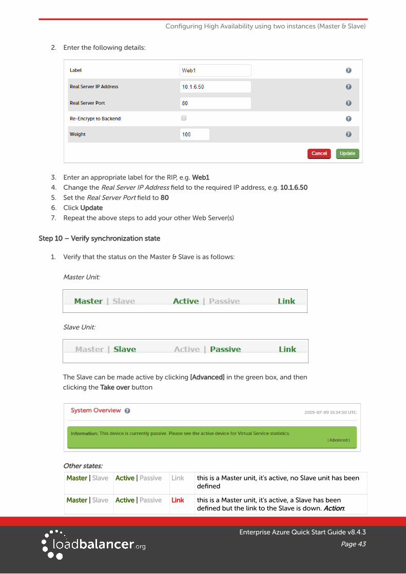
2. Enter the following details:
3. Enter an appropriate label for the RIP, e.g. Web1
4. Change the Real Server IP Address field to the required IP address, e.g. 10.1.6.50
5. Set the Real Server Port field to 80
6. Click Update
7. Repeat the above steps to add your other Web Server(s)
Step 10 – Verify synchronization state
1. Verify that the status on the Master & Slave is as follows:
Master Unit:
Slave Unit:
The Slave can be made active by clicking [Advanced] in the green box, and then
clicking the Take over button
Other states:
Master | Slave Active | Passive Link this is a Master unit, it's active, no Slave unit has been defined
Master | Slave Active | Passive Link this is a Master unit, it's active, a Slave has been defined but the link to the Slave is down. Action:
Enterprise Azure Quick Start Guide v8.4.3
Page 43

Configuring High Availability using two instances (Master & Slave)
check & verify the heartbeat configuration
Master | Slave Active | Passive Link this is a Slave unit, it's active (a failover from the Masterhas occurred) and the heartbeat link to the Master has been established
Step 11 – Testing & Verification
• Connect to the Public IP address of the Azure Load balancer and verify that you can access the load balanced service. Use the Take Over button on the passive device and verify that the service isstill available – the failover time will depend on the settings for the health probe, but using default values should complete in under 10 seconds.
10. Testing – General Comments
TESTING LOAD BALANCED SERVICESFor example, to test a web server based configuration, add a page to each web servers root directory, e.g. test.html and put the server name on this page for easy identification during the tests.
Use two or more clients to do the testing. Open up a web browser on each test clients and enter the URL for the VIP, e.g. http://104.40.133.119
Provided that persistence is disabled, each client should see a different server name because of the load balancing algorithm in use, i.e. they are being load balanced across the cluster.
Why test using two clients? If you use a single client it will most likely keep on hitting the same server for multiple requests. This is to do with the way that the load balancing algorithms are optimized.
DIAGNOSING VIP CONNECTION PROBLEMS
1. Make sure that the device is active – this can be checked in the WebUI. For a single appliance, the status bar should report Master & Active as shown below:
2. Check that the Real Servers are up – Using System Overview make sure that none of your VIPs are colored red. If they are, the entire cluster is down (i.e. all Real Servers). Green indicates a healthy cluster, yellow indicates that your cluster may need attention (one or more of the Real Servers may be down), and blue indicates all Real Server have been deliberately taken offline (by using either Halt or Drain).
Enterprise Azure Quick Start Guide v8.4.3
Page 44
Testing – General Comments
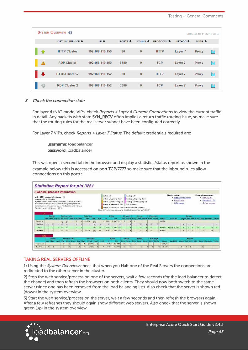
3. Check the connection state
For layer 4 (NAT mode) VIPs, check Reports > Layer 4 Current Connections to view the current traffic in detail. Any packets with state SYN_RECV often implies a return traffic routing issue, so make sure that the routing rules for the real server subnet have been configured correctly
For Layer 7 VIPs, check Reports > Layer 7 Status. The default credentials required are:
username: loadbalancer
password: loadbalancer
This will open a second tab in the browser and display a statistics/status report as shown in the
example below (this is accessed on port TCP/7777 so make sure that the inbound rules allow connections on this port) :
TAKING REAL SERVERS OFFLINE1) Using the System Overview check that when you Halt one of the Real Servers the connections are redirected to the other server in the cluster.
2) Stop the web service/process on one of the servers, wait a few seconds (for the load balancer to detect the change) and then refresh the browsers on both clients. They should now both switch to the same server (since one has been removed from the load balancing list). Also check that the server is shown red (down) in the system overview.
3) Start the web service/process on the server, wait a few seconds and then refresh the browsers again. After a few refreshes they should again show different web servers. Also check that the server is shown green (up) in the system overview.
Enterprise Azure Quick Start Guide v8.4.3
Page 45

Testing – General Comments
The System Overview shows the status as these tests are performed:
In this example:
RIP1 is green, this indicates that it's operating normally
RIP2 is blue, this indicates that it has been either Halted or Drained. in this example Halt has been used as indicated by Online (Halt) being displayed. If it had been drained it would show as Online (Drain)
RIP3 is red, this indicates that it has failed a health check
USING REPORTS & LOG FILESThe appliance includes several logs and reports that are very useful when diagnosing issues. Both are available as main menu options in the WebUI. Details of both can be found in the administration manual.
11. More InformationPlease refer to our website for the latest administration manual, deployment guides and all otherdocumentation: https://www.loadbalancer.org/uk/resources/manuals
12. Loadbalancer.org Technical SupportIf you have any questions regarding the appliance or how to load balance your application, please don't hesitate to contact our support team using the following email address: [email protected]
Enterprise Azure Quick Start Guide v8.4.3
Page 46

Company Contact Information
13. Company Contact Information
Website URL: w w w.loadbalancer.org
North America (US) Loadbalancer.org, Inc.
4550 Linden Hill Road, Suite 201Wilmington, DE 19808USA
Tel:Email (sales):
Email (support):
+1 [email protected]@loadbalancer.org
North America (Canada) Loadbalancer.org Appliances Ltd.300-422 Richards StreetVancouver, BCV6B 2Z4Canada
Tel:Email (sales):
Email (support):
+1 [email protected]@loadbalancer.org
Europe (UK) Loadbalancer.org Ltd.Compass HouseNorth Harbour Business ParkPortsmouth, PO6 4PSUK
Tel:Email (sales):
Email (support):
+44 (0)330 380 [email protected]@loadbalancer.org
Europe (Germany) Loadbalancer.org GmbHTengstraße 2780798MünchenGermany
Tel:Email (sales):
Email (support):
+49 (0)89 2000 [email protected]@loadbalancer.org
Enterprise Azure Quick Start Guide v8.4.3
Page 47