engineering standards for subdivisions - City of St. Catharines
102
CITY OF ST. CATHARINES ENGINEERING STANDARDS FOR SUBDIVISIONS JUNE, 1992 PREPARE BY: Engineering Department Development Section
Transcript of engineering standards for subdivisions - City of St. Catharines

CITY OF ST. CATHARINES
ENGINEERING STANDARDS
FOR SUBDIVISIONS
JUNE, 1992
PREPARE BY: Engineering Department Development Section
THE CORPORATION OF THE CITY OF ST. CATHARINES
MUNICIPAL ENGINEERING STANDARDS
FOR SUBDIVISION DEVELOPMENT
ENGINEERING DEPARTMENT
JUNE 1992
(Digital Copy Prepared July 2009)

- 1 -
INDEX Page
SECTION 1 GENERAL REQUIREMENTS 3
SECTION 2 ENGINEERING SUBMISSION REQUIREMENTS 7
SECTION 3 ROADS 22
SECTION 4 SANITARY SEWERS 30
SECTION 5 STORM SEWERS 40
SECTION 6 WATER DISTRIBUTION SYSTEM 52
SECTION 7 LOT GRADING AND SURFACE DRAINAGE 62
SECTION 8 STANDARD DRAWINGS 66
- 2 -
SECTION 1
GENERAL REQUIREMENTS
Page
1.1 GENERAL 3
1.2 GENERAL REQUIREMENTS 3
1.3 FUNCTIONAL REPORT 4
1.4 ENGAGEMENT OF PROFESSIONAL ENGINEER 5
1.5 PROFESSIONAL ENGINEERING SERVICES 5
1.6 ENGINEERING FEES 6

- 3 -
CITY OF ST. CATHARINES
STANDARD DRAWINGS
Series Title
100 Abbreviations and Legend
200 Grading
300 Entrances and Sidewalk Construction
400 Road Sections
500 Concrete Curbs and Gutters
600 Sanitary and Storm Sewers
700 Guide Rails and Fencing
800 Watermains
- 4 -
1.1 GENERAL The following sections outline the City of St. Catharines requirements for all
engineering submissions forwarded to the City for approval of individual and residential construction within the areas of its jurisdiction with respect to subdivision development.
The City of St. Catharines reserves the right to alter any of these requirements
within the text of each Subdivision Development Agreement. Where the development is being processed under the Ministry of Housing’s
Draft Plan Approval, two copies of the draft plan and conditions is required before engineering submissions will be reviewed by the City.
All drawings and documents submitted to the City are to be in a standard metric
scale and on standard City of St. Catharines sheets where applicable. Prior to commencement of detailed design, it is advisable that the developer
and/or his consultant meet with City Engineering staff to clarify the City’s requirements for engineering submissions.
1.2 GENERAL REQUIREMENTS All developments shall include the following, unless otherwise stated; a) Roads, including hot mix, hot laid asphalt pavement,
b) Curbs and gutters,
c) Private walkways and public sidewalks,
d) Storm and Sanitary Sewers and services,
e) Street names and regulatory signs,
f) Watermains, hydrants and water services,
g) Underground utilities (Hydro, telephone, gas, Cable TV., etc.)
h) Street lighting,
i) Tree planting,
- 5 -
j) Sodding of boulevards and all residential lots,
k) Grading to ensure adequate surface drainage,
l) Landscaping,
m) Fencing
1.3 FUNCTIONAL REPORT The need for a Functional Report will be established by City staff during the
review of the development application. The Functional Report (if required) shall include, but not necessarily be limited to, the following information:
a) Roadway Network - impact of the development on any roads within or abutting the
Development b) Sanitary Sewer System - drainage areas and proposed flows, - main sizing, location and outlets, - treatment facilities and pumping stations (if required). c) Storm Sewers and Storm Water Management - drainage areas and proposed flows - designation of major and minor drainage systems – direction of flow and
outlet, - storm water management facilities, - main sizing, location and outlets. d) Water System - main sizing, location and looping - pressure boundaries, booster stations and treatment facilities (if
required).
- 6 -
1.4 ENGAGEMENT OF PROFESSIONAL ENGINEER The Development Applicant shall retain for any and all development projects, a
Professional Engineer licensed to practice in the Province of Ontario, who is experienced in the design and execution of land development projects and is acceptable to the City of St. Catharines.
Inspection during construction may be carried out by the City, or a consultant
hired by the City and the cost of such undertaking shall be included in the City’s Engineering Fees.
1.5 PROFESSIONAL ENGINEERING SERVICES The professional Engineer retained by the applicant will prepare and execute
the following activities in conjunction with the requirement of the City of St. Catharines Engineering Department:
a) Preliminary investigation and report, b) Pre-engineering survey, c) Soils investigation d) Final design and report, e) Plan, specifications, tender documents and contracts, f) Cost estimate, g) Applications, h) Calling of tenders, i) Analysis of bids and recommendations to the applicant and City staff, j) Setting out the work, k) General administration of construction (as per A.P.E.O.) l) Resident Supervision of construction (as per A.P.E.O.) m) As-constructed drawings, n) Coordination of all utilities (gas, telephone, hydro, cable T.V., etc.)

- 7 -
1.6 ENGINEERING INSPECTION FEES The developer shall pay, prior to execution of the development agreement with
the City, an amount of money equal to a percentage of the estimated construction costs of all storm sewers, culverts, sanitary sewers, watermains, roads, curbs and sidewalks and all other construction works pertinent to the development under the jurisdiction of the City of St. Catharines.
The amount of money to be paid for inspection shall be determined by the
following scale of fees: i) 4.5 percent of the total cost of services up to $100,000.00, with a
maximum payment of $4,500.00; plus ii) 4 percent of the total cost of services in excess of $100,000.00 up to
$400,000.00 with a minimum of $4,500.00; plus iii) 3.5 percent of the total cost of services in excess of $400,000.00 and
shall be payable in cash or certified cheque to the Corporation of the City of St. Catharines.

- 8 -
SECTION 2
ENGINEERING SUBMISSION REQUIREMENTS
Page
2.1 GENERAL 8
2.2 LETTER OF TRANSMITTAL 8
2.3 ENGINEERING DESIGN BRIEF 8
2.4 ENGINEERING DRAWINGS 9
2.5 CONTRACT DOCUMENTS 17
2.6 COST ESTIMATE AND PROPOSED CONSTRUCTION SCHEDULE
17
2.7 PREPARATION OF DEVELOPMENT AGREEMENT 17
2.8 AS-BUILT AND LOCATION PLANS FOR SERVICES 18
- 9 -
2.1 GENERAL Prior to the preparation and execution of a subdivision development agreement,
the City of St. Catharines requires a complete submission of Engineering Drawings and Specifications to be provided by the developer’s Consulting Engineer to the City’s Engineering Department for their technical review and comment.
A complete submission constitutes the following items: a) A letter of transmittal, b) Engineering design brief, c) Engineering drawings, d) Contract documents, e) Construction cost estimate and proposed construction schedule. 2.2 LETTER OF TRANSMITTAL The letter can be a standardized form or a formal letter indicating the
submission date and number, contents of the submission package, and the name of the appropriate contact personnel.
2.3 ENGINEERING DESIGN BRIEF The engineering design brief is a technical report summarizing the intent of the
project, and outlines the design assumptions, calculations, supporting documentation and references to previous studies, for each component of the development.
- 10 -
2.4 ENGINEERING DRAWINGS 2.4.1 General a) Drawing size shall be A1 (600mm x 900mm) b) Plan and Profile – horizontal metric scale shall be 1:500 - vertical metric scale shall be 1:50 c) Metric scale for general plans shall be a minimum of 1:1000, d) Original material used for all drawings shall be Mylar Mat surface on
working side or equivalent, e) All drawings shall be neat, legible and completed in ink, g) All sewers, watermains, manholes, manhole numbers, pipe diameter,
direction of flow, pipe class and bedding, and service connections shall be shown on all drawings,
h) Where plans require more than one drawing, match lines shall be
provided, showing both reference drawing numbers, preceding and following, plus station,
i) A complete set to drawings shall include:
i) Title Sheet
ii) General Plan of Services
iii) General Lot Grading Plan
iv) Sanitary Drainage Area Plan
v) Storm Drainage Area Plan
vi) Plan and Profile Drawings
vii) Construction Details (where required)
viii) Street Lighting Plan (where required)
ix) Plan Index (where required)

- 11 -
2.4.2 Title Sheet The Title Sheet shall include the following: a) Name of the Development b) Name of the Developer c) City of St. Catharines d) Name of the Consulting Engineer e) Key Plan at a scale of 1:10,000 indicating the location of the proposed
development and the proposed new street alignment f) Index to each drawing constituting the complete set indicating drawing
number and title g) Approvals 2.4.3 General Plan of Services To a scale of 1 to 1000. showing the following: a) Roads, lots and their numbers, b) Sanitary and storm sewers including pipe diameter and direction of flow c) Watermains, hydrants and valves, d) Manholes and catchbasins, e) Culverts and easements, f) Existing streets and services surrounding the development and their
relation to the proposed work, g) Location and description of all available benchmarks.
- 12 -
2.4.4 General Lot Grading Plan To a scale of 1:500 showing the following: a) Existing and proposed elevations at all lot corners, b) Existing contouring at 500 mm elevation intervals for the area under
consideration, including sufficient area of the adjacent lands to establish the overall drainage pattern,
c) Proposed road elevations at 25 m intervals, at changes in grade, and at
all intersections, and the location of catchbasins, proposed top of curb elevation in front of each lot,
d) Percentage grade along the gutter at the outside edge of road for any
cul-de-sac, e) Minimum basement floor elevations of proposed structures susceptible to
basement flooding, f) Proposed apron elevation of all houses, g) Proposed ground elevation at the rear or all rear walkouts, rear back split
and front split lots, or where steep grades from the front to the rear of the lot are encountered,
h) Proposed drainage easement and rear yard swales and invert elevations
or rear yard swales, i) Direction of surface drainage on individual lots, j) Proposed rear lot catchbasins and top elevations, k) Typical sections for all proposed drainage courses and swales, l) Existing surface drainage features such as ditches, channels, ponds or
swamps, m) For each lot, a proposed drainage type shall be specified,

- 13 -
m) Typical detail drawings of proposed drainage types as per City of St.
Catharines Standards shall be included, n) All proposed embankments with hatched lines and proposed top and toe
of embankment elevations and degree of slope, i.e. 3:1. 4:1, o) Location of all proposed retaining walls and proposed elevations
including cross-sections, p) Location of all street catchbasins, q) Any additional plans, sections and details that may be required for
drainage courses, major overland storm routing and erosion protection, irregular or steep topography, and screening and noise abatement as may be requested by the City Engineer.
2.4.5 Sanitary Drainage Area Plan To a scale of 1 to 1000, unless otherwise approved by the City Engineer
showing the following: a) Proposed sanitary sewers, manholes and appurtenances, indicating
grade, pipe size, type of pipe, length of each section of pipe and direction of flow,
b) Drainage areas within the development and the limits of outside areas
within the development and the limits of outside areas draining into the proposed system,
c) Area in hectares, direction of flow and section population or population
density shall be indicated on all drainage areas. 2.4.6 Storm Drainage Area Plan (Minor System) To a scale of 1 to 1000, unless otherwise approved by the City Engineer
showing the following:

- 14 -
a) Proposed storm sewers, manholes, catchbasins indicating grade, pipe
size, type of pipe, lengths and direction of flow, b) Ditches, culverts and ponds, where required, showing all necessary
information as above, c) Drainage areas within the subdivision and the limits of areas outside the
plan draining into the proposed system, d) Area in hectares, direction of flow and runoff coefficient shall be indicated
on all drainage areas. 2.4.7 Major Storm System Flow Plan To a scale of 1 to 1000, unless otherwise approved by the City Engineer
showing the following: a) Major storm system flow route along streets and easements including
controlling elevations, grades, direction of flow and sizes of conduits and swales incorporated in the system,
b) Limits of area outside the plan draining through the proposed major
system, c) All existing drainage channels and the method or incorporating these
channels into the proposed major system, d) Location of catchbasins and size of orifice plates limiting flow in the
catchbasins leaders (if required). e) Detention or retention basis, f) When split drainage is utilized, the major system overland routes from the
rear lot catchbasins should be shown. 2.4.8 Plan and Profiles of Road Plan and profile drawings must be drawn for all streets within the subdivision as
well as for any existing streets upon which the subdivision may front any service easements.

- 15 -
The City shall designate chainages for roads forming a continuation of existing
streets. All chainages shall be calculated along the street centrelines. There must be at least two ties provided per sheet to determine the relationship of the road centerline to the property bars.
All appurtenances and construction details are to referred to applicable City
Standard Drawings or Ontario Provincial Standards Drawings (OPSD). Any design details not covered by the above should be put in the form of special
design standards and attached with the contract plans with the approval of the City Engineer.
Plan and Profile drawing shall be drawn at a horizontal scale of 1 to 500 and at
a vertical scale of 1 to 50, and shall show the following: a) Existing and proposed sewer, giving for each section the size, material
class, pipe grade, and bedding requirements, b) All sewer appurtenances. The manholes must be numbered on both the
plan and the profile. Designation between sanitary manhole numbers and storm manhole numbers must be shown,
c) Details of manholes such as number, location standard details and grate
elevations should be shown, d) All manhole inverts must be given and adequately described on the
profile, e) Rear yard catchbasin invert elevations, f) Existing ground profile is to be indicated as a broken line, g) Proposed centerline of road profile (top of pavement), giving grades,
chainage of P.V.I.’s and vertical curve data are to be shown, h) Radius and angle of intersection as well as tangent arc length and chord
should be shown for all horizontal curves, i) Chainage of B.C., E.C. and P.I., etc. is to be shown on the plan and
indicated as such,

- 16 -
j) The names of streets are to be given outside and above the road
allowance. k) Curb radii must be given at all intersections and on bends, where
applicable. l) Location and description of the nearest benchmark on each drawing. 2.4.9. Construction Details Any particular detail drawing referenced on any of the preceding drawings or
any additional particular detail drawing required by the Engineer. 2.4.10 Street Lighting Plan To a scale of 1 to 1000 showing the following: a) Roads, lots and their numbers, b) The position of all new light standards within the development, c) The position of existing light standards surrounding the development and
their relation to the proposed work, d) A detail of, and tabulated specifications for the type of luminaire
proposed. All design shall be in accordance with the “Guide for Design of Roadway
Lighting” as developed by the Road and Transportation Association of Canada (RTAC).

- 17 -
2.4.12 Information Required for Approval of Engineering Design Two copies of each of the following documents shall be submitted to the City of
St. Catharines Engineering Department. a) Proposed final plan for registration (M-plan), b) Reference plan for easements being conveyed to the City, c) Complete set of Engineering Drawings, d) Sanitary sewer design calculations, e) Storm sewer design sheets utilizing standard City form, f) A soils consultant report if deemed necessary by the City, g) Calculations for pipe strength and bedding requirements, 2.4.13 Procedure for MOE Approval 1. Developer or his consultant, submits four (4) copies of completed application
forms for storm, sanitary or water works. Submission must include: a) Letter or form of transmittal b) Engineer’s report c) Supporting documentation – servicing study, charts, graphs, etc. d) Plan and profile drawings e) Contract specifications – detail drawings and standards f) General and Drainage Area Plans g) Design sheet and computations h) Certificate of Approval i) Environmental Assessment Exemption Affidavit (when appropriate) j) Corporate Business Return (for private developments)

- 18 -
2. City submits applications to Regional Niagara for approval on behalf of the
applicant. 3. Region makes necessary policy checks and submits application and data to
the MOE with a recommendation. 4. MOE reviews submission and issues Certificate of Approval if requirements
met. 2.5 CONTRACT DOCUMENTS Upon final Engineering submission for approval of the Engineering Drawings, two (2) copies of the Contract Documents for the project are required to be provided to the City of St. Catharines Engineering Department for their review. Prior to commencement of construction of services, three copies of the Contract Documents, one with prices and two without plus four (4) sets of contract drawings are required to be provided to the City’s Engineering Department. The Contract Documents shall include all addenda and the Form of Tender. 2.6 COST ESTIMATE AND PROPOSED CONSTRUCTION SCHEDULE An itemized cost estimate for the construction of the works in a form acceptable to the City of St. Catharines is required along with a breakdown of any items designated to be cost-shared. A proposed construction schedule for all construction activities is to be provided to the City’s Engineering Department. During the progress of the work, any revisions to the original schedule shall be forwarded to the City. 2.7 PREPARATION OF DEVELOPMENT AGREEMENT The draft of the development agreement will be prepared by the City of St. Catharines Planning Department and forwarded to the City Solicitor. The solicitor will then prepare the final agreement and obtain Council approval for execution of the agreement by the City. Prior to the preparation of the draft agreement, the City must be in receipt of the following information:

- 19 -
a) The name of the person and/or company with whom the development
agreement will be executed, b) The name, address and telephone number of the subdivider’s lawyer, c) A breakdown of the number of units proposed within the development: i.e. - single family units - semi-detached units - multi-attached units - apartment units d) A detailed cost estimate prepared by an engineer for services to be constructed
for the development, e) Two (2) copies of the engineering drawings, f) Three (3) copies of the reference plans for any easement to be granted to the
City. 2.8 AS-BUILT DRAWINGS AND LOCATION PLANS FOR SERVICES
2.8.1 General a) As-Built Location Plans Upon preliminary acceptance of services, the required location plans for
as constructed measurements are to be completed and submitted to the City’s Engineering Department showing all necessary details for underground service installations.
One reproducible copy of each location plan is to be submitted to the
City.
- 20 -
As-built locations plans are required for the following: i) Sanitary Services - location of service tie connections at the main line sewer are to be
dimensioned along the mainline sewer from each manhole, - location of services at streetline are to be dimensioned from the lot
corners and the elevation of the service invert at streetline is to be recorded,
ii) Storm Services and Catchbasin Leads - location of service and catchbasin lead tie connections at the main line
sewer are to be dimensioned along the main line sewer from each manhole,
- location of services at streetline are to be dimensioned from the lot
corners and the elevation of the service invert at streetline is to be recorded,
- catchbasin locations are to be dimensioned as a distance along the
storm sewer from the nearest manhole and the elevation of the catchbasin rim and lead invert recorded.
iii) Watermain Valves, Tees and Appurtenances and Water Services - the location of watermain valve box and valve chambers are to be
dimensioned up or down the road from the nearest manhole and an offset distance from the centerline of the road or back of the curb,
- water service main stops are to be dimensioned along the alignment of
the water main from the nearest valve and curb stops and boxes are to be dimensioned from lot corners.
- 21 -
Where watermains are not within road allowances or near sewers, ties to
property corner shall be used. b) As-Built Drawings “As-built” Drawings constitute the original Engineering Drawings which
have been revised to show “As-built” conditions. The “As-Built” drawings shall be submitted to the City for their permanent records,
c) “As-built” information on all drawings and location plans is to be
completed in ink, d) As stated, final measurement locations plans are to be completed and
submitted at time of preliminary acceptance of services. “As-built” drawings are to be submitted to the City Engineering Department for checking and microfilming purposed no later than six months after preliminary acceptance of top asphalt.
2.8.2 As-Built Field Survey The “as-built” revisions shall be based upon an “as-built” survey of all the
development services and shall include a field check of the following items: a) Location of manholes for all utilities b) Location of catchbasins, c) Location of hydrants, d) Location and ties to valve chambers and valve boxes, e) Manhole inverts, f) Pipe sizes, g) Distance between manholes, h) Special manhole details, i) Catchbasin inverts.

- 22 -
2.8.3 As-Built Drawings
The “as-built” drawings for all the Municipal Services shall incorporate all
revisions found in completing the “as-built” field survey and include a check of the following items and incorporation of the necessary revisions.
a) Percent grade – sewers, b) Invert elevations – sewers at manholes, at plugs for future extensions, c) Top of pipe and/or invert elevations – watermains, where necessary, eg.
where watermain has been varied from normal depth requirements, in field, to avoid conflict with other buried services.
d) Top of watermain and sanitary sewer at centerline of creek crossing. Note: Original design information (inverts, grades, etc.) is to remain on
drawings but crossed out, with as-built information shown adjacent to original information.
eg. – E.Inv. 97.5 (Original Design Invert) 97.62 (As Constructed Invert) e) Pipe type, class and bedding, f) House connections – sanitary, storm and water g) Label “As-built Drawings” (shown in revision column with date), h) Registered Plan Number is to be shown on plan view of each drawing
including general plans, i) Lot and block numbers shall be in conformity with the registered plan, j) Street names shall be in conformity with the registered plan or as
approved by the municipality.
- 23 -
SECTION 3
ROADS
Page
3.1 ROADS 23
3.2 CURBS 26
3.3 SIDEWALKS 27
3.4 BOULEVARDS 27
3.5 DRIVEWAY ENTRANCES 27
3.6 DAYLIGHTING 28
3.7 FOOTPATHS AND WALKWAYS 28
3.8 EMERGENCY ACCESSES 28
3.9 STREET NAME AND TRAFFIC SIGN REQUIREMENTS 28
3.10 UTILITY INSTALLATIONS 29
3.11 STREET LIGHTING 29
3.12 ELECTRICAL DISTIRUBTION 29

- 24 -
3.1 ROADS
3.1.1 General Road classification is designated by the MTO and shall be subject to the
approval of the City Engineer. Generally, residential roads are classified as either arterial, collector or
local. Arterial roads are intended to carry large volumes of traffic, moving at
medium to high speeds. Arterial roads serve the major traffic flows between the principal traffic generators and connect with collectors and freeways. Design of arterial roadways are to meet the requirements of the controlling authority.
Collector roads provide for both traffic service and land access. The
primary traffic service function is to carry traffic between local streets and arterial roadways. The City of St. Catharines classifies collector roads as any roadway which, in the opinion of the City and the MTO.
a) will serve as access to 100 or more homes, b) will serve as a traversing route for residents outside of the
subdivision. A local road’s function is to provide for land access to those properties
which directly front on it.
3.1.2 Clearing and Grubbing The road allowance shall be cleared of all trees and shrubs except
where they are to be included in final landscaping, and other obstructions for such widths as are required for the proper installation of all roads, services, and other works. Rough grading shall be done to bring the travelled portion of the road to the necessary grade and in conformity with the cross-section shown on the drawings.

- 25 -
The sub-grade for all roads shall be properly shaped and thoroughly
compacted prior to any application of granular base course materials. In all cases, topsoil shall be stripped for the complete width of the right-of-way and stockpiled at locations approved by the City Engineer.
3.1.3 Geometric Design Standards
Local Road Collector Road Minimum grade 0.4% 0.5% Maximum grade 8.0% 8.0% Maximum Grade for
Thorugh Roads at Intersection
3.5% 3.0%
Maximum Grade for
Stop Roads at Intersections
2.5% 2.0% at Local 1.5% at Collector
Minimum Curb Radius
at Intersection with Arterial Road:
9 m 13 m
Minimum Curb Radius
at Intersection with Collector Road:
9 m 13 m
Cul-de-Sac Minimum
Outside Curb Radius 15 m N.A.
Minimum Island Curb
Radius 7.5 m N.A.
R.O.W. 16m/18m/20m** 20 m Pavement Width 8.5 *** 10 m*** Minimum Centreline
Radius 60 m* 85 m
Design Speed N/A 60 kph
- 26 -
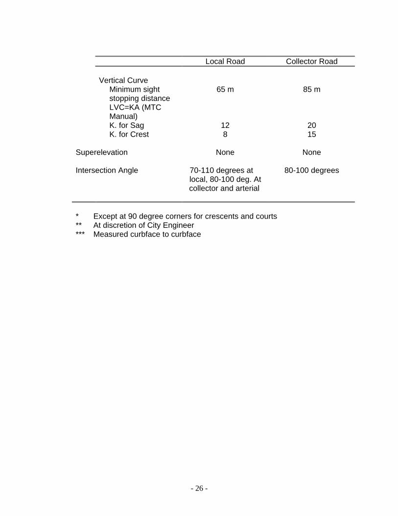
Local Road Collector Road Vertical Curve Minimum sight
stopping distance 65 m 85 m
LVC=KA (MTC Manual)
K. for Sag 12 20 K. for Crest 8 15 Superelevation None None Intersection Angle 70-110 degrees at
local, 80-100 deg. At collector and arterial
80-100 degrees
* Except at 90 degree corners for crescents and courts ** At discretion of City Engineer *** Measured curbface to curbface

- 27 -
3.1.4 Alignment Horizontal and vertical alignment is to conform to the requirements as
outlined in Section 3.1.3 Geometric Design and the Ontario Provincial Standard Drawings.
All curves must meet the geometric design standards. Vertical curves are required for changes in grade greater than 1% for
collector and 1.5% for locals. The minimum length of each grade is 6 metres. “Culs-de-sac” are to
have a minimum grade of 0.5% around the longest curb, to ensure adequate surface drainage.
3.1.5 Road Pavement Desing The pavement design for arterial roads will be considered on an
individual basis. The composition and construction thickness of the road pavement shall be designed based upon the following factors:
a) Mechanical analysis of the subgrade soil, b) Drainage, c) Frost susceptibility, d) The future volume and class of traffic expected to use the
pavement. Pavement shall be designed for a minimum ADT – 1000 vehicles and an
anticipated life for 20 years. 3.1.6 Road Allowance Cross-Section The typical road allowance cross-section shall be as per OPS except for
semi-urban cross-section which will be in accordance with the City’s Standard Drawings. Details shall be provided for any approved special provisions required due to unique physical conditions on the site or for existing or future design conditions such as retaining walls, slope protection, culverts, bridges or special crossfall conditions.

- 28 -
3.1.7 Intersections At the intersection of two roads, any transition of the minor classification
road shall not interfere with the normal crossfall of the major road. A 1% to 2% backfall grade shall be provided on all road profiles where local streets intercept with arterial roads. The backfill grade shall be from the crown of the major road to the E.C. or first catchbasin on the local road.
3.1.8 Road Sub-Drains In general, sub-drains will be required to run continuous along both sides
of all roads, as per the City’s standard drawing. However, the City will consider reducing sub-drain requirements for a particular development where a recognized soils consultant indicates that there will be no adverse effects to the road either during or after construction.
In all cases, sub-drains will be required for a minimum length of 6 m on
the upstream side of all catchbasins.
3.2 CURB Curb as shown on Ontario Provincial Standard Drawing shall generally
be used on local streets, “Capping” of curb depressions will not be permitted.
Sawcutting of curb depressions will be allowed. Mountable curbs as per
Ontario Provincial Standard Drawing may be used on the approval of the City Engineer.
Two stage curb poured construction in accordance with City Standard
Drawing may be used with the approval of the City Engineer.

- 29 -
3.3 SIDEWALKS
Concrete sidewalks as per City Standard Drawing shall be constructed
on a) both sides of arterial streets b) at least one side of the collector streets c) at least one side of these streets which serve as a school approach d) at such other locations as may be determined by the Planning
Department of the City of St. Catharines
3.4 BOULEVARDS All boulevards shall be sodded on a minimum of 100 mm of topsoil from
curb line to property line and shall be kept free of rubbish and other materials during the development.
All sod that fails to grow, or dies within one year of placement, shall be
replaced at the developer’s expense.
3.5 DRIVEWAY ENTRANCES The Subdivider shall be required to provide for the excavation, stoning
and maintenance in good condition of each driveway from the travelled portion of the road to the lot line.
The width of curb cut for residential driveways shall be as per City
Standards. The width of curb cut for apartment, commercial and industrial driveways shall take into account the basic width of the driveway and the radius of curvature as further outlined below. Where mutual driveways are constructed between two adjoining properties, the curb cut-out shall be continuous. (Where the curb is less than 1 metre between driveways).
The maximum grade permissible for an access driveway, from the
curbline to the garage shall be 10%. This maximum grade is not recommended and should be employed only in exceptional cases where physical conditions prohibit the use of lesser grades. There shall be a minimum grade of 2% from the streetline to the curbline where sidewalk exists.
- 30 -
The radius of curvature from the road into apartment, commercial and industrial driveways shall be designed to accommodate the anticipated vehicular traffic without causing undue interference with the traffic flow on the street (ARTC Traffic Turning Templates).
Standard Entrances access are as per Ontario Provincial Standard
Drawings.
3.6 DAYLIGHTING When subdivision streets intersect with collector or arterial or local
streets, the Engineer may request land for daylighting triangles. The size of the daylighting required is based on the classification of the intersecting roads and shall be in accordance with Standard Drawing. The City Engineer may request additional daylighting above these requirements if he deems it necessary.
3.7 FOOTPATHS AND WALKWAYS A 1.2 metre wide concrete sidewalk as per City Standard Drawings and
a minimum, 1.5 metre high chain link fence on both sides along property line is required on all footpaths and walkways. The chain link fence shall be reduced to 0.9 m in height from the building setback to the street line.
3.8 EMERGENCY ACCESSES A minimum width of 3.9 metres; 225 m base course stone; 50 mm H.L.
#3 surface course asphalt. Where walkway is incorporated with the emergency access the width shall be 4.5 m.
3.9 STREET NAME AND TRAFFIC SIGN REQUIREMENTS The owner shall pay the cost of the supply and installation of permanent
street name and traffic signs. Sufficient traffic control signs, as determined by the Engineer, shall be installed to ensure the safe and efficient flow of traffic.
- 31 -
3.10 UTILITY INSTALLATION
Location and installation details for utilities must be approved by the City
Engineer prior to the installation. All utility trenches within the road allowance are to be backfilled and
compacted to 95% Standard Proctor Density. Backfill material shall be in accordance with the requirements of the City Engineer.
3.11 STREET LIGHTING The subdivider shall arrange for the design and installation of all lighting
facilities, including lamp standards, conduits, lamps and control mechanisms in accordance with current RTAC standard. The type, number of lights and their location together with the estimated cost of the total installation thereof, must be approved by the City Engineer. The suddivider shall supply City and/or the local electrical supply authority with easements wherever they are required.
3.12 ELECTRICAL DISTRIBUTION Design and installation of the electrical distribution system for the
proposed development is to meet the requirements of the local hydro authority. Underground street wiring and wiring to the lots and houses are mandatory. In circumstances where underground wiring is not practical, an alternative may be agreed upon. The subdivider shall supply the City and/or the local electrical supply authority with easements wherever they are required.

- 32 -
SECTION 4
SANITARY SEWERS
Page
4.1 DESIGN FLOWS 31
4.2 SEWER DESIGN 31
4.3 EASEMENTS 36
4.4 PIPE MATERIALS 36
4.5 SANITARY SEWER SERVICE CONNECTION 37
4.6 CONSTRUCTION 39
- 33 -
4.1 DESIGN FLOWS Calculation of sewage design flows shall conform to the latest editions of the
Regional Municipality of Niagara, Public Works Department’s “Guidelines for the Design and Construction of Sewer and Watermain Systems”, and the Ontario Ministry of the Environment’s “Guidelines for the Design of Water Storage Facilities, Water Distribution Systems, Sanitary Sewage Systems and Storm Sewers”.
4.2 SEWER DESIGN
4.2.1 Sewer Design Sewer capacities shall be computed by using Manning’s Formula on the basis
of sewer pipe flowing full.
4.2.2 Roughness Coefficients For all types of pipe, a roughness coefficient of n = 0.013 shall be used.
4.2.3 Velocity and Grade Minimum velocity 0.75 m/s – minimum grade 0.4% for all local sewers, except
the minimum grade of the first upstream leg is 0.6%.

- 34 -
Sewer Size (mm) Minimum Slope (%) 200 0.40 250 0.35 300 0.30 350 0.26 375 0.23 400 0.21 450 0.18 525 0.14 600 0.12 675 0.10 750 0.09 825 0.08 900 0.07
4.2.4 Minimum Size 200 mm diameter
4.2.5 Minimum Depth Depth is measured from the final centerline finished road elevation to the top of
the sanitary sewer. For residential, commercial and institutional areas, the minimum depth is 2.5
metres. For industrial areas, the minimum depth is 2.15 metres. In all cases, the proposed sanitary sewers shall be installed at sufficient depth
to service lands external to the site as determined by the City.
- 35 -
4.2.6 Location
Sanitary sewers shall be located in the centre of the road allowance, as shown
on Standard Drawing. If common trenching is required for the storm and sanitary sewer, the subdivider’s consultant shall prepare special design standards and provide to the City the specification for such requirements. Any non-standard design for locations will required the approval of the City Engineer.
4.2.7 Manholes a) Manholes shall be constructed of poured or precast concrete as detailed
on the Ontario Provincial Standards Drawing. b) Manholes shall be provided at each change in alignment, grade, pipe
material and at all junctions, and at the points of connection over 200 mm in diameter where the size of connection is equal to or one size smaller than the City sewer.
c) Manholes shall generally be spaced at a maximum of 106 metres for
pipe sizes 200 mm diameter to 450 mm diameter, a maximum of 137 metres for pipe sizes greater than 450 mm.
d) The type and size of manhole shall be specified on the profile and a
detail of the benching is to be shown on the plan portion of the engineering drawing for cases when the benching differs from the normal.
e) All manhole chamber openings shall be located on the upstream side of
the manhole. f) The maximum change in the direction of flow in any sanitary sewer
manhole shall be 90 degrees. A change of flow direction at acute interior angles shall not be permitted.

- 36 -
g) The maximum drop allowed across a manhole is 0.9 m. If the design of
the sewer system is such that the difference in elevation between the manhole inlet and outlet will exceed 0.9 m, then a drop structure will be required.
h) When pipe size does not change through a manhole and the upstream
flow velocity does not exceed 1.5 m/s, the following allowances shall be made to compensate for hydraulic losses:
Alignment Change Drop Required a) Straight run grade of sewer b) 15 – 45 degrees 0.03 m c) 45 – 90 degrees 0.06 m When the upstream flow velocity exceeds 1.5 m/s, the drop required
through a manhole shall be calculated. i) For all junction and transition manholes, the drop required shall be
calculated. j) The obvert (s) on the upstream side of a manhole shall in no case be
lower than the obvert (s) on the downstream side of the manhole. k) All manholes shall be benched as detailed on the O.P.S. l) All benching inside manholes shall be a minimum of 225 mm in width. m) The Standard Drawings provide details for manholes up to certain
maximum depths, the Consulting Engineer shall analyze individually, each application of the standards, related to soil conditions, loading and other pertinent factors, to determine structure suitability. In all cases where the standards are not applicable, manholes must be individually designed and detailed.
n) When any dimension of a mahole exceeds those on the Ontario
Provincial Standards, the manhole must be individually designed and detailed.

- 37 -
Safety gratings shall be required in all manholes in accordance with the Ontario
Provincial Standards. Safety gratings shall not be more than 4.0 metres apart and shall be constructed in accordance with the Standard Drawings.
4.2.8 Pipe a) The class, type of pipe and type of pipe bedding shall be shown on the
profile for each section of sewer. b) The use of radius pipe for deflected pipe will be permitted to achieve
changes in horizontal alignment for sewer sizes 1050 mm diameter and larger. The minimum radius allowed for various pipe diameters shall be as detailed in the manufacturer’s specifications. When pipes are deflected at the joints, the angle of joint displacement shall not exceed 3 degrees.
c) In general, no decrease of pipe size from a larger size upstream to a
small size downstream will be allowed regardless of increase in grade. d) Pipe bedding and class of pipe shall be designed to suit ultimate loading
conditions. e) Generally, service connections shall not be permitted to sanitary sewers
exceeding 7.60 metres in depth. Depth is measured from the final centerline finished road elevation to the top of the sanitary sewer.
f) Generally a minimum clearance of 225 mm shall be provided between
the outside of the pipe barrels at the point of pipe crossing for storm sewers and other utilities except for watermain crossings when the minimum clearance shall be no less than 0.5 m.
In the event the minimum clearance of 225 mm cannot be obtained then
the pipes at the crossing shall be concrete encased to ensure that the pipes are properly bedded.
- 38 -
4.3 EASEMENTS The minimum width of easements for pipes shall be determined by the
developer’s consulting engineer to account for number of pipes, pipe size, depth and excavation of open cut method. In no case shall the easement width be less than 3.0 metres.
The developer must grant permanent easements for any drainage works which
are not within the road allowance, to the City. 4.4 PIPE MATERIALS
4.4.1 Sanitary sewer shall be constructed of polyvinyl chloride, concrete, or polyethylene pipes.
a) Concrete Sewer Pipe 450 mm in diameter and smaller shall conform to
CSA Specification or latest revision thereof, Standard Strength or Extra Strength, as required.
b) Reinforced Concrete Sewer Pipe 300 mm in diameter and larger shall be
steel reinforced and shall conform to CSA Specifications or latest revision thereof, Class II, III, IV or V, as required.
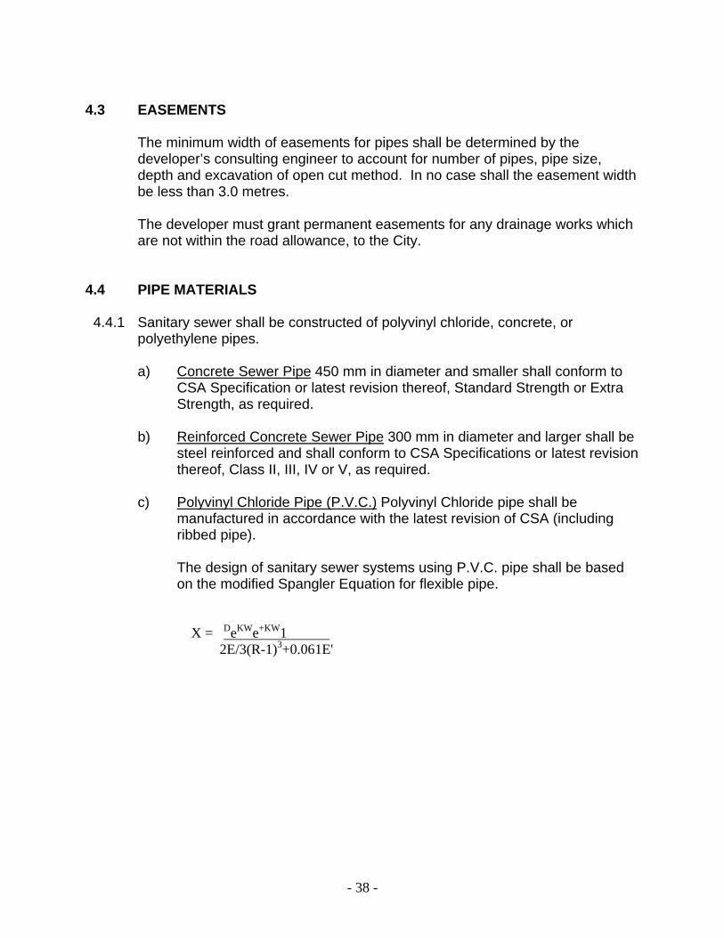
c) Polyvinyl Chloride Pipe (P.V.C.) Polyvinyl Chloride pipe shall be
manufactured in accordance with the latest revision of CSA (including ribbed pipe).
The design of sanitary sewer systems using P.V.C. pipe shall be based
on the modified Spangler Equation for flexible pipe. X = DeKWe+KW1 .
2E/3(R-1)3+0.061E'

- 39 -
Where X = Vertical deflection of pipe (cm) De = Deflection lag factor (1.5 for plastic pipe) K = Bedding factor DR = Dimension ratio We = Earth load on pipe (N/L in metre) W1 = Live load on pipe (N/L in metre) E = Modulus of elasticity of pipe material
(for pvc 1120, E=2.76XX109 pa) E' = Modulus of soil reaction For main sewers, the Standard Dimension Ration (S.D.R.) of the P.V.C.
pipe shall not exceed S.D.R.35. For service connections the Standard Dimension Ratio of the P.V.C. pipe
shall not exceed S.D.R.28. The bedding required for P.V.C. main sewer and service connections
shall be as detailed on the standard drawings. d) Polyethylene Pipe (P.E.) – Polyethylene pipe shall be manufactured in
accordance with the latest revision of either C.S.A.B137.0 and C.S.A.B137.1 or C.G.S.B.41-GP-25.
4.5 SANITARY SEWER SERVICE CONNECTION
4.5.1 General All sanitary sewer service connections for single and semi-detached
dwelling shall be individual services. The connection to the main sewer shall be made with an approved
manufactured tee or approved saddle.
- 40 -
In new developments, the service connections shall be installed in
accordance with the Standard Drawings terminating 0.9 m inside the property line.
4.5.2 Pipe Size a) Service connections for single family and semi-detached units shall be
100 mm diameter. b) Service connections for multiple family and other blocks, Commercial,
institutional Areas – to be sized individually according to the intended use.
4.5.3. Depth The depth of the service connections for single family units and semi-detached
units, at the street line, measured from the final centreline road elevation shall be:
Minimum – 2.50 metres Maximum – 3.00 metres Risers shall be used when the invert depth of the sewer main exceeds 4.0
metres. The riser connection shall not exceed 3.0 metres in depth.

- 41 -
4.5.4. Velocity and Grade
Minimum low flow velocity – 0.60 m/s Minimum Grade - 100 mm diameter connection – 2% - 150 mm diameter connection – 1%
4.5.5 Sanitary Sewer Connections to Commercial and Industrial Blocks A manhole shall be required located on private property 1.50 metres from
property line to centre of rim as per Regional requirements.
4.5.6 Materials for Sanitary Sewer Service Connections Sanitary sewer service connections may be constructed using any of the
materials outlined in Section 4.4.1 except for polyethylene, which is not listed as an acceptable material under The Plumbing Code.
4.5.7. Location of Service Connections Sanitary connections shall be located in accordance with the applicable
standard drawing.
4.6 CONSTRUCTION Construction of all sanitary sewers and service connections in the City of St.
Catharines shall be in accordance with the current and appropriate Ontario Provincial Standard Specifications and Standard Drawings.

- 42 -
SECTION 5
STORM SEWERS
Page
5.1 GENERAL 41
5.2 RATIONAL METHOD 41
5.3 SEWER DESIGN 45
5.4 PIP 48
5.5 PIPE MATERIALS 49
5.6 STORM SEWER SERVICE CONNECTIONS 50
5.7 CONSTRUCTION 51
5.8 ROOF LEADERS 51
5.9 ALTERATIONS TO EXISTING WATERCOURSES 51
- 43 -
5.1 GENERAL Determination of stormwater design flows for both the major and minor drainage system for development shall conform to the contents of the latest edition of the City of St. Catharines “Storm Drainage Manual”. The developer and/or his Consulting Engineer shall meet with the City Engineering Department prior to commencement of detailed design to establish the acceptable methodology for determination of stormwater design flows, required by the City. Where the rational method of determination of storm design flows is acceptable, the following section may be used. 5.2 RATIONAL METHOD
5.2.1 General The design of the storm sewers shall be computed on the Standard Design
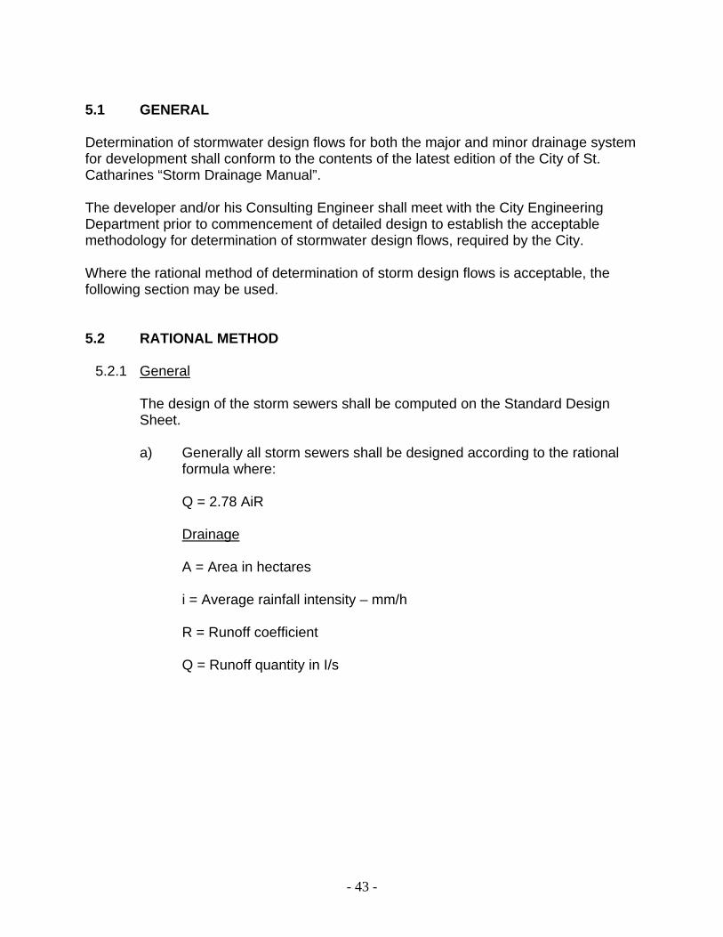
Sheet. a) Generally all storm sewers shall be designed according to the rational
formula where: Q = 2.78 AiR Drainage A = Area in hectares i = Average rainfall intensity – mm/h R = Runoff coefficient Q = Runoff quantity in I/s
- 44 -
5.2.2 Watershed and Drainage Areas
The watershed area shall be determined from contour plans and shall include
all areas that naturally drain into the system and shall also consider all lot grading plans for proposed developments.
A plan of the watershed area shall be prepared and shall include all affected
streets, lots and watercourses. The proposed storm sewer system shall be shown on this plan including each manhole numbered consecutively for design reference. Manholes shall be located at each and every change of pipe size, grade and alignment.
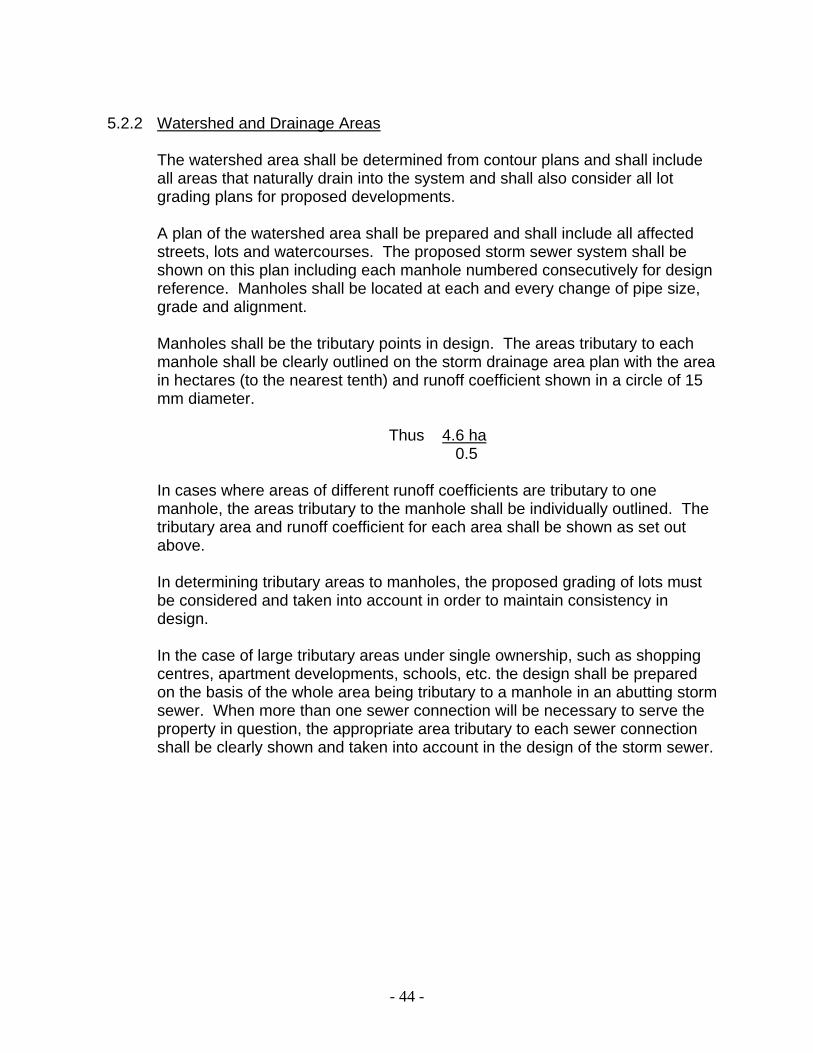
Manholes shall be the tributary points in design. The areas tributary to each
manhole shall be clearly outlined on the storm drainage area plan with the area in hectares (to the nearest tenth) and runoff coefficient shown in a circle of 15 mm diameter.
Thus 4.6 ha
0.5 In cases where areas of different runoff coefficients are tributary to one
manhole, the areas tributary to the manhole shall be individually outlined. The tributary area and runoff coefficient for each area shall be shown as set out above.
In determining tributary areas to manholes, the proposed grading of lots must
be considered and taken into account in order to maintain consistency in design.
In the case of large tributary areas under single ownership, such as shopping
centres, apartment developments, schools, etc. the design shall be prepared on the basis of the whole area being tributary to a manhole in an abutting storm sewer. When more than one sewer connection will be necessary to serve the property in question, the appropriate area tributary to each sewer connection shall be clearly shown and taken into account in the design of the storm sewer.

- 45 -
In lieu of precise information on development of the whole or any part of a
watershed area, the latest approved Zoning By-law and Plans shall be used to select the correct values of the runoff coefficients to be used in the design and to determine the specific areas where they will apply.
5.2.3 Rainfall Intensity
The values of the rainfall intensity shall be determined using the approved IDF
Curves from the City “Storm Drainage Manual”. Storm frequency values for both the minor and major systems are as follows: i) Minor System – 5-year Storm ii) Major System – 100-Year Storm (for all watercourses) Generally, inlet time or initiation time of concentration is to be 10 minutes. For
specific situations refer to the City “Storm Drainage Manual”. 5.2.4. Runoff Coefficients
Values for the runoff coefficient “R” shall be approved by the City Engineer.
Listed below are recommended runoff coefficients: SURFACE TYPE OF LAND USE RECOMMENDED COEFFICIENT Parks C=0.20 Schools C=0.40 Single Family Residential C=0.40 Semi-Detached C=0.45 Maisonettes, Townhouses, etc. C=0.50 Churches C=0.60 Apartment C=0.70 Industrial C=0.70 Commercial C=0.80 Paved Areas C=0.90 or 1.00

- 46 -
5.2.5 Storm Water Detention When a storm sewer connection is not available to a particular site, the existing
combined sewer or road side ditch may be used as a storm sewer outlet subject to the approval of the City Engineer provided the rate of flow to the combined sewer or ditch it not increased after the development of the site is completed. On-site detention may be required and can be accomplished by means of rooftop detention, parking lot detention or green area detention. Ministry of the Environment and Ministry of Natural Resources approvals are required for all systems
When storm water detention is required, a detailed design must be submitted
indicating that the site can be developed while, at the same time, providing the necessary detention areas. The design shall include the method of detention together with the volumes of storm water to be detained, drainage area plans, design flow calculations and the method of restricting the flow from the site calculations showing volume of area on site to be utilized, as well as the path of flow where detention is exceeded. In addition, release calculations and velocities for these flows should be included.
* EAST ST. CATHARINES
WEST ST. CATHARINES
Major System N/A
Detention of flows in excess of 1:5 year storm but less than 1:100 year
storm
Minor System
Detention of excess flow from 1:5 year storm to
level determined by City Engineer
N/A
When development takes place in areas where Flood Plain Mapping has been carried out, approval must be obtained from the Niagara Peninsula Conservation Authority and the Ministry of Natural Resources.
Also refer to the City of St. Catharines Storm Drainage Manual.
* In general terms, the boundary is the Twelve Mile Creek

- 47 -
5.3.3 Slope of Storm Sewer Pipe The minimum design velocity for storm sewer is 0.75 metres per second. The
following are the minimum slopes which shall be provided for storm sewers: Pipe Size Minimum Slope o/o 100 mm 1.0 150 mm 1.0 200 mm 0.5 300 mm 0.303 375 mm 0.226 450 mm 0.178 525 mm 0.144 600 mm 0.120 675 mm 0.102 750 mm 0.089 825 mm 0.080 900 mm 0.070 1050 mm 0.056 1200 mm 0.048 1350 mm 0.042 1500 mm 0.036 1650 mm 0.031 1800 mm 0.028 1950 mm 0.025 2100 mm 0.023 5.3 SEWER DESIGN
5.3.1 Pipe Capacity Manning’s Formal shall be used to compute the capacity of storm sewers. The
capacity of the sewer shall be calculated on the basis of the pipe flowing full.
5.3.2 Roughness Coefficient The roughness coefficient to be used for storm sewer pipes shall be: a) Concrete Pipe: n = 0.013 for all sizes of pipes b) Vitrified Clay: n = 0.013 for all sizes of pipes c) Asbestos Cement: n = 0.013 for all sizes of pipes d) Corrugated Metal: n = 0.124 for all sizes of pipes
- 48 -
5.3.4 Velocity The velocity in storm sewers shall be generally limited to a minimum of 0.75
m/s and a maximum of 6.0 m/s.
5.3.5 Minimum Sizes of Pipe Sewer Mains - 300 mm Catchbasin Connections - 200 mm
5.3.6 Minimum Depth The minimum cover to the top of pipe shall generally be 2.40 metres. In all cases, the proposed storm sewers shall be installed at sufficient depth to
service lands external to the site as determined by the City.
5.3.7 Location Storm sewers shall be located on the south and west side of the road
allowance, 1.5 metres from the centreline as shown on Standard Drawing. If common trenching is required for the storm and sanitary sewer, the subdivider’s consultant shall prepare special design standards and provide to the City the specification for such requirements. Any non-standard design for locations will require the approval of the City Engineer.
5.3.8 Manholes a) Manholes shall be provided at each change in alignment, grade and
pipe material. b) Generally, manholes shall be spaced at - a maximum of 100 metres for pipe sizes 250 mm diameter to 750 mm
diameter, - a maximum of 120 metres for pipe sizes 825 mm diameter to 1200 mm
diameter, - a maximum of 150 metres for pipe sizes greater than 1200 mm
diameter.
- 49 -
c) The type and size of manhole shall be specified on the profile and a
detail of the benching shall be shown on the plan portion of the drawing for cases when the benching differs from the normal.
d) All manhole chamber openings shall be located on the upstream side of
the manholes. e) Storm sewer pipe greater than 525 mm shall not be turned more than 90
degrees in any manhole. In cases where there is more than one inlet, no storm sewer greater than 450 mm shall be turned at 90 degrees in a manhole.
f) The maximum change in direction of flow in manholes for sewer sizes
1050 mm and over shall be 45 degrees. g) The direction of flow in any manhole will not be permitted at acute
interior angles. h) The minimum drop across the manhole for all straight runs shall be
sufficient to maintain the design head. i) The obverts on the upstream side of a manhole shall, in no case, be
lower than those on the downstream side. j) All benching inside manholes shall be as determined in the Ontario
Provincial Standards Drawing. k) When the dimensions of a manhole exceed those on Standard
Drawings, the manhole must be individually designed and detailed. l) Safety gratings shall be required in all manholes greater than 4.0 metres
in depth. Safety gratings shall not be more than 4.0 metres apart and constructed in accordance with the Ontario Provincial Standard Drawings.

- 50 -
5.3.9 Inlet and Outfall Structures
Inlet and Outfall structures including headwalls shall be fully designed and
submitted in detail. Developers should contact the Niagara Peninsula Conservation Authority to ascertain permit requirements.
Grates shall be provided on all inlet and outfall structures 600 mm in diameter
and larger and shall be fully designed and detailed including locks where applicable.
In general, inlet grates shall consist of vertical parallel bars or rods sloping
approximately 45 degrees away from and in the direction of the flow. Outlet grates shall consist of horizontal bars or rods placed perpendicular to the flow. Spacing between the bars or rods shall not exceed 150 mm. See OPSD # 403.01.
The spacing of catchbasins shall be as follows: Road Gradient Maximum Spacing 0.5% to 3% 90 m 3% to 5% 75 m 5% to 6% 60 m Where changes of grade occur, the average gradient shall determine the
maximum spacing. Catchbasins should not be located within 1.5 metres of a curb depression for a driveway or sidewalk. At intersections, catchbasins shall be installed so that no more than 15 metres of gutter will drain past the upstream point of tangency.
In sags, when drainage is received from more than one direction, double
catchbasins shall be installed and the maximum length of gutter contributing from each side shall be 75% of the spacing permitted above.
Catchbasins are permitted in rear yards to permit drainage to the storm system
on the street. Catchbasins shall conform to the Ontario Provinicial Standard Drawings.
- 51 -
5.4 PIPE
a) The class and type of pipe bedding shall be shown on the profile for all
lengths of sewer. b) All storm sewers shall be located as shown on the appropriate road
cross-section standard. c) Generally, the pipe sizes shall not decrease from a larger size upstream
to a smaller size downstream regardless of the increase in grade. d) Subject to the approval of the Engineer, radius pipe will be permitted to
achieve changes in horizontal alignment. The minimum radius allowed for various diameters of pipe shall be as detailed in the manufacturer’s specifications.
e) Pipe bedding and class shall be designed to suit ultimate loading
conditions. f) Generally a minimum clearance of 225 mm shall be provided between
the outside of the pipe barrels at the point of pipe crossing for storm sewers and other utilities except for watermain crossings, then the minimum clearance shall be no less than 0.6 metre.
In the event that the minimum clearance of 225 mm cannot be obtained,
then the pipes at the crossing shall be concrete encased to insure that the pipe are properly bedded.
5.5 PIPE MATERIALS
5.5.1 Storm sewers shall be constructed of concrete pipe, polyvinyl chloride pipe or polyethylene pipe. Corrugated metal piping may be used for culverts. The classification of pipe to be used shall be clearly indicated on the plans.
a) Concrete sewer pipe 450 mm in diameter and smaller shall conform to
CSA Specification, or latest revision thereof, Standard Strength or Extra Strength as required.
b) Reinforced Concrete Sewer Pipe 300 mm in diameter and larger shall
be steel reinforced and shall conform to CSA Specification, or latest revision thereof, Class II, III, IV or V, as required.

- 52 -
c) Corrugated steel pipe shall conform to A.A.S.H.O. Specifications M218,
M136, M190 and M167. d) Polyvinyl chloride pipe should be manufactured in accordance with the
latest revisions of C.S.A. B137.0 and C.S.A. B137.1 and including ribbed pipe.
e) Polyethylene Pipe shall be manufactured in accordance with the latest
revision of either C.S.A. B137.0 and C.S.A. B137.1 or CGSB 41-GP-25.
5.5.2 Pipes shall be jointed by means of approved rubber gaskets.
5.6 STORM SEWER SERVICE CONNECTIONS (where required)
5.6.1 General The storm sewer connections to the main sewer shall be made with an
approved manufactured tee for main sewer sizes up to and including 375 mm diameter and in accordance with City requirements for larger sizes.
Cathbasins are required at all low points in the road and at low grade points at
intersection. Additional catchbasins should be provided along the roadway at the following maximum distances:
The maximum distances are based on the capacity of a standard 24-inch
square grate on pavement widths up to 32 feet. Road Grades Spacing Up to 3% 350 feet 3 – 4.5% 300 feet Greater than 4.5% 250 feet Double catchbasins or special catchbasins shall be used where the inlet
capacity of a single catchbasin is exceeded, or at a sag point. Inlet capacity can be computed using the following formula: Q = CA 2gH x 0.67 Where ‘Q’ is the inlet capacity in cfs, ‘C’ is the orifice co-efficient equal to 0.6
for square edge openings or 0.8 for round edge openings, ‘H’ is the allowable
- 53 -
head over the inlet in feet, ‘A’ is the inlet area in square feet, and ‘g’ is the acceleration due to gravity which is equal to 32.2 feet per second.
Special catchbasins and inlet structures shall be fully designed and detailed.
For Single Catchbasins, the connection shall not be less than 8 inches diameter pipe laid at 0.50 percent grade.
For double catchbasins, the connection shall not be less than 10 inch. diameter
pipe laid at 0.50 percent grade. 5.6.2. Pipe Size
Storm sewer connections for multiple family and other blocks, Commercial and
Industrial Areas – to be sized individually according to the intended use.
5.6.3. Depth The depth of service connections at the street line in residential areas,
measured from the final centreline road elevation shall be: Maximum - 1.80 metres Minimum - 2.50 metres Risers shall be used when the invert depth of the sewer main exeeds 4.0
metres. Risers shall not exceed 3.0 metres in depth.
5.6.4 Storm Drainage and Storm Sewer Connections to Multiple Family, Commercial and Other Blocks
Parking lots, driveways, and/or other hard surfaced areas servicing multiple
family, commercial and other blocks, shall be drained by a properly designed internal drainage system (including catchbasins, manholes and pipe) which shall connect to the storm sewer system or other approved outfall.
5.6.5 Velocity
Minimum velocity - 0.80 m/s Maximum velocity - 3.65 m/s
5.7 CONSTRUCTION Construction of all storm sewers and service connections in the City shall be in
accordance with the current and appropriate Ontario Provincial Standard Specifications and Standard Drawings.

- 54 -
5.8 ROOF LEADERS & FOUNDATION DRAINS
Roof and foundation drain connections to storm laterals are expressly
prohibited. Instead, they should discharge at the front of the building unless otherwise approved by the City Engineer onto splash pads with flows directed away from the building foundations without erosion or inconvenience to others. Wherever possible, runoff from roof drains should flow across pervious ground surfaces. Weeping tile must be installed in all rear yard swales connected to the rear yard swales connected to the rear yard catchbasins to prevent ponding in the rear yards of buildings caused by drainage from roof and surface areas.
5.9 ALTERATIONS TO EXISTING WATERCOURSES
Where existing drainage courses are to be altered by filling or diversion, the
Developer must ensure that satisfactory drainage is maintained and that no ponding will occur upstream. The Niagara Peninsula Conservation Authority has regulations applying to all watercourses which govern the construction in any area susceptible to flooding by the 100 year storm sewer and govern the placement of fill in any area which may affect flooding, pollution or conservation of land. In general, all alterations to existing watercourses must satisfy the requirements of the City, the Niagara Peninsula Conservation Authority and the Ministry of Natural Resources.

- 55 -
SECTION 6
WATER DISTRIBUTION SYSTEMS
Page
6.1 HYDRAULIC DESIGN 53
6.1.1 DESIGN WATER DEMANDS 53
6.1.2 SYSTEM PRESSURES 53
6.1.3 FRICTION FACTORS 53
6.2.1 WATERMAIN AND APPURTENANCES 54
6.2.2 VALVES 57
6.2.3 FIRE HYDRANTS 58
6.2.4. WATER SERVICES 59

- 56 -
6.1 HYDRAULIC DESIGN
6.1.1 DESIGN WATER DEMANDS Determination of watermain design flows shall conform to the latest edition of
the Ontario Ministry of the Environment’s Guidelines for the Design of Water Storage Facilities, Water Distribution Systems, Sanitary Sewage Systems and Storm Sewers” and the Regional Municipality of Niagara Public Works Department’s “Guidelines for the Design and Construction of Sewer and Watermain Systems”.
6.1.2 SYSTEM PRESSURES
The maximum sustained operating pressures shall not exceed 700 kPa.
Where pressures in localized area are above this level, pressure-reducing valves shall be installed.
The distribution system shall be sized to meet normal peak demands. Under
conditions of simultaneous maximum day and fire flow demands, the pressure shall not drop below 140 kPa. Under normal operating conditions, the pressure shall not drop below 275 kPa.
All watermains shall be capable of withstanding minimum design pressure of
1035 kPa regardless of the working pressure in the system or the rating necessary to meet the structural requirements of the trench condition. (Design Pressure = maximum sustained internal hydrostatic pressure to which the pipe is to be subjected, excluding transient pressures).
6.1.3. FRICTION FACTORS
The following “C” values shall be used for the design of water distribution
systems regardless of pipe materials: Pipe Diameter (mm) C-Factor 150 100 200 to 250 110 300 to 600 120 Over 600 130
- 57 -
The above C-factors represent long term values. A C-factor of 130 shall be
used to calculate maximum velocities for transient pressure estimations, and for checking pump motor sizes for runout conditions.
6.2.0 WATERMAIN AND APPURTENANCES 6.2.1. WATERMAINS
6.2.1.1 Sizes
Sizes and looping of watermains will be determined at the preliminary stage of
the development. The following are the minimum size requirements. Residential Areas – 150 mm diameter minimum, 200 mm diameter will be
required on dead end streets. Industrial Areas – Sized according to the anticipated demand for industrial
subdivisions.
6.2.1.2 Depth of Cover The minimum depth of cover to watermains should not be less than the depth
of frost penetration. Generally the depth of cover shall not be less than 1.70 metres measured in a
vertical plane above the pipe from the top of the pipe to the finished ground elevation.
It will be the responsibility of the developer or his engineer to justify any
reduction in the depth of cover less than 1.70 metres by submitting a report outlining the reasons for the reduction and alternative frost protection measures to be taken.

- 58 -
6.2.1.3 Vertical Separation Between Watermains and Sewers Under normal conditions, the vertical separation between the crown of
the sewer and the invert of the watermain shall be at least 0.5 metre. 6.2.1.4 Horizontal Separation Between Watermains and Sewers Under normal conditions, watermains shall be laid with a horizontal
separation of at least 2.50 metres from any sewer or sewer manhole. The distance shall be measured from the nearest edges.
6.2.1.5 Separation of Watermain and Sewers – Special Conditions Under unusual conditions, where a significant portion of the
construction will be in rock, where it is anticipated that severe dewatering problems will occur, or where congestion with other utilities will prevent a clear horizontal separation of 2.50 metres, a watermain may be laid closer to a sewer, provided that the elevation of the crown of the sewer is at least 0.50 metres below the invert of the watermain. Such separation shall be in-situ material or compacted backfill.
Where this vertical separation cannot be obtained, the sewer shall be
constructed of materials and with joints that are equivalent to watermain standards of construction and shall be pressure tested to assure water tightness.
In rock trenches, facilities should be provided to permit drainage of
the trench to minimize the effects of impounding of surface water and/or leakage from sewers in the trench.
- 59 -
6.2.1.6 Crossings of Watermains Over and Under Sewers
Under normal conditions, watermains shall cross above sewers with sufficient vertical separation to allow for proper bedding and structural support of the watermain and sewer main.
When it is not possible for the watermain to cross above the sewer, the
watermain passing under a sewer shall be protected as follows: a) A vertical separation of at least 0.50 metre shall be provided between
the invert of the sewer and the crown of the watermain. b) The sewers shall be adequately supported to prevent excessive
deflection of joints and settling. c) The length of watermain shall be centred at the point of crossing so that
the joints will be equidistant and as far as possible from the sewer. 6.2.1.7 Utility Crossings Where watermains cross over or under utilities other than sewers, the
clearance and type of crossing provided shall conform to the requirements of the particular utility involved and provide proper bedding and structural support of the watermain and utility.
6.2.1.8 Dead Ends Wherever possible, the distribution system shall be designed to eliminate
dead-end sections. Where dead-ends cannot be avoided, they shall be provided with a fire hydrant, flushing hydrant or a 50 mm blowoff for flushing purposes.

- 60 -
6.2.2.0 LINE VALVES 6.2.2.1 Type
Gate valves shall be used on all watermains 250 mm diameter or less in size.
Butterfly valves shall be used on all watermains of 300 mm diameter and greater.
All valves shall be of the approved type with non-rising stem and a 200 mm
square operating nut opening counterclockwise.
6.2.2.2 Sizes The sizes of the line valves shall be the same size as the watermain.
6.2.3.3 Number, Location and Spacing Generally, a minimum of two valves are required at a tee intersection and a
minimum of three valves are required at a cross intersection. The valves shall be located at the point where the projections of the streetline intersects the watermain. Valve boxes and chambers shall be located in boulevards whenever possible.
Line valves shall be located such that 20 houses can be shut-off from another
block and isolated from the system. In no case shall the spacing exceed 305 metres.
Line valves on feedermains shall be spaced from 762 to 915 metres.
6.2.2.4 Air Release Valves Air release valves shall be placed at all significant high points of the
distribution system. In addition, an attempt shall be made to locate hydrants at high points or at dead ends, thereby eliminating the need for vacuum-air relief valves and/or blow-offs.
- 61 -
6.2.2.5 Drain Valves
Drain valves shall be located at the low points of all watermains of 600 mm
diameter and greater.
6.2.2.6 Valve Boxes and Chambers All valves 250 mm diameter and smaller shall have valve boxes and specified
direct bury operators shall be used. All valves 300 mm diameter and larger shall be installed in valve chambers. The tops of valve boxes and valve chamber manhole covers shall be set flush
with finished grade. The top of the roof slab of valve chambers shall be at least 0.60 metre below the profile of the finished pavement.
Chambers or pits containing valves, blow-offs, meters or other such
appurtenances to a distribution system shall not be connected directly to any sanitary or combined sewer, nor shall blow-offs or air-relief valves be connected directly to any such sewer.
Such Chambers or pits shall be drained to the surface of the ground where
they are not subjected to flooding by surface water, to absorption pits or to a sump within the chamber where ground water level is above the chamber floor or storm sewer.
In order to minimize the total number of chambers on any project, care should
be exercised in locating the line valves, air reliefs, drains, etc., with a view to combining these functions in a single chamber.
6.2.3 FIRE HYDRANTS 6.2.3.1 Fire protection for industrial and commercial development shall be reviewed
upon application.
- 62 -
6.2.3.2 Hydrants
Hydrant installation shall be as per City Standard Drawing.
6.2.3.4 Hydrants-Numbers and Spacing Hydrants shall be installed on all watermains 150 mm diameter and larger
with the following maximum allowable spacing: a) 150 metres in residential areas, or to provide for a maximum hose
length of 75 metres, b) 75 metres in industrial and commercial areas to provide for a maximum
hose length of 37.5 metres.
6.2.3.4 Branch Valves and Boxes All hydrants installed on watermains shall be installed with 150 mm diameter
branch valve and box.
6.2.4 WATER SERVICE CONNECTION 6.2.4.1 General
In new developments, the service connections shall be installed in
accordance with the Standard Drawings terminating at the property line. No service connection shall be made to watermains greater than 400 mm
diameter.

- 63 -
6.2.4.2 Pipe Sizes
a) The minimum size for service connections shall be 20 mm diameter
except when the length of the connection from the main to the building setback exceeds 30 metres, then the minimum size shall be 25 mm diameter.
b) Service connections for multiple family dwellings shall be sized to
provide capacity equivalent to a 20 mm diameter connection to each dwelling unit.
c) Service connections for blocks, commercial and industrial areas shall be
sized according to the intended use.
6.2.4.3 Location Water service connections shall be installed at the mid-point of the frontage of
a single family lot. Water service connections shall not be located under a driveway, if possible.
The location of water service connections for semi-detached lots shall suit the house style in accordance with the Standard Drawing.
6.2.4.4 Death
Curb and Gutter Roads – water service connections shall be installed 1.70
metres minimum below finished centerline road grade. Open Ditch and Unimproved Roads – in no case shall the cover of the water
service connection be less then 1.70 metres.
6.2.4.5 Mainstops All domestic water service connections shall have mainstops installed at the
watermain equal to the water service connection diameter.
- 64 -
6.2.4.6 Curb Stops and Boxes
All service connections shall have curb stops and boxes installed at an
approved location.
6.2.4.7 Materials Water service connection 50 mm diameter or less shall be type “K” copper or
polyethylene. Water service connections larger than 50 mm diameter shall be polyvinyl chloride. All material, fittings and appurtenances shall be CSA and A.W.W.A. approved.
6.2.4.8 Cathodic Protection
Cathodic protection must be provided for all cast iron pipes and
appurtenances.

- 65 -
SECTION 7
LOT GRADING AND SURFACE DRAINAGE
Page
7.1 GENERAL 63
7.2 OBJECTIVES 63
7.3 DESIGN CRITERIA 64
7.4 PREGRADING 65
- 66 -
7.1 GENERAL
New development lot grading shall conform to the latest edition of the City of St. Catharines “Storm Drainage Manual”. Such lot grading must be prepared by a P. Eng. Or O.L.S.
At the time of final acceptance the Consulting Engineer shall provide the City
with an as-built grading plan for the subdivision showing the finished grade of all key points as of a certain date. Minor variations will be allowed, provided the intent of the proposed approved plan was followed and there is not problems. This plan must carry the following certifying statement, signed and sealed by a Professional Engineer or O.L.S.
“I have taken the field elevations shown ( ), and hereby certify that the
house grade and the grading of each lot or block is in conformity with the submission for a building permit. I further certify that as of this date that each lot or block within this subdivision drains satisfactorily and the grading of this subdivision has not adversely affected adjacent lands.”
It will be the responsibility of the developer to ensure that lot grading is
completed to the satisfaction of the City Engineer. Lot grading shall be in accordance with the approved drawings.
Any deviation from the overall grade plan will require approval of the City
Engineer.
7.2 OBJECTIVES The lot grading plan will be reviewed and, therefore, should be designed with
the following objectives in mind: a) The establishment of independent and adequate drainage for each lot.
This can be provided by either rear to front drainage or split drainage intercepted in a rear yard swale, catchbasins, etc.
b) The establishment of lot and house grades which are compatible with
existing topography and surrounding development. This will achieve maximum utility and protection for the property and enhance its appearance.
c) The establishment of gradual gradation without terraces, steep slopes,
or abrupt changes in grade. These are not only difficult to maintain, but also accentuate the artificiality of the new topography.
d) Defined ditch like swales should be avoided.
- 67 -
7.3 DESIGN CRITERIA a) The maximum allowable difference in elevations between abutting lots
along the rear lot line is 0.3 metres. The slope should be located on the lower property.
b) Slopes shall have not less than a 3:1 slope unless approved by the City
Engineer. c) The use of rear yard swales, embankments or retaining walls should be
minimized. d) Grass surfaces shall have a minimum slope of 1%. e) Grading around houses and buildings shall direct the water away from
the structure. f) Swale depth will vary depending on location and safety consideration
(preferably not more than 500 mm). g) Swale grades are recommended to be at least 1.0 percent. In clay-type
soils swales shall be underdrained. h) The maximum runoff typically allowed in a swale between two houses is
the drainage from those two yards. i) The maximum swale length shall not exceed 90 metres. Such drainage
shall not outlet along the surface between houses. Not more than 6 lots shall be serviced by one basin.
j) When rear lot catchbasins are installed to pick up surface drainage, the
municipality maintains them, in which case, easements must be provided by the developer. The width of such easements shall be 3 m.
k) The proposed elevations at the boundary of the subdivision shall match
existing elevations and accept any surface drainage from the adjacent lands.
l) Provision is to be made to prevent ponding of water on lands bordering
the subdivision and within the subdivision during construction. m) Where below grade garage driveways are designed, the portion
between the property line and street must drain towards the street.
- 68 -
7.4 PREGRADING The subdivision shall be pregraded prior to issuance of building permits and the
Consulting Engineer shall clarify that such work has been done. Pregrading requires that all lot corners, rear yard catchbasins, swales and underdrainage of same and boulevards have been constructed in accordance with the “General Grading Plan”. The Niagara Peninsula Conservation Authority may have specific concerns related to pregrading. Consultations with the NPCA prior to and during the pregrading of the site is recommended.

- 69 -
SECTION 8
STANDARD DRAWINGS
All references are to Ontario Provincial Standard Drawings except the City Standards listed below:
1. 16 m Road Section
2. 18 m Road Section
3. 20 m Road Section
4. Sidewalk
5. Storm Sewer Service Connection
6. Hydrant
7. Water Valves Locations
8. Typical Lot Grading

- 70 -
SECTION 8
STANDARDS DRAWINGS
All references are to Ontario Provincial Drawings except the City Standards listed below:
SECTION TOPIC REFERENCE
NUMBER DESCRIPTION
3 Roads 110-1102 16 m Road Section 110–1103 18 m Road Section 110-1101 20 m Road Section 110-1221 Concrete Curb and Gutter Detail 110-1206 Curb and Gutter Detail 110-1201 Standard Sidewalk Detail 110-1218 Sidewalk Ramp Details 4 Sanitary Sewers 110-1222 Foundation Drain Connection 5 Storm Sewers 110-1301 Rainfall Intensity Duration Curve 6 Water Distribution 110-1401 Hydrant Assembly 110-1403 Standard Location for Mains and Hydrants at Intersections 110-1404 Standard
Arrangements for Water Services 110-1405 Standard 50 mm
Blowoff Assembly
- 71 -
110-1407 Standard Hydrant
Assembly 110-1408 Standard Location
for Mains and Hydrants at Intersections with 25’ curb radii
110-1409 Typical Location for
Watermain Thrust Blocks
110-1410 Typical Thrust
Blocks for Horizontal Bends
- 72 -
SECTION TOPIC REFERENCE
NUMBER DESCRIPTION
110-1412 Recommended
Service and Meter Size for Apartments
110-1414 Typical Watermain
Bedding and Backfilling
110-1415 Colour Coding for
Painting Fire Hydrants
110-1416 Vertical Bend Thrust
Blocks 110-1417 Cathodic Protection 110-1418 Typical Service
Entrances 110-1419 Typical Watermain
Undercrossing 7 Lot Grading and
Surface Drainage 110-1306 Drainage Type A
110-1307 Drainage Type B 110-1308 Drainage Type C 110-1306 Drainage Type D 110-1307 Drainage Type E 110-1308 Drainage Type F 110-1309 Lot Drainage Notes
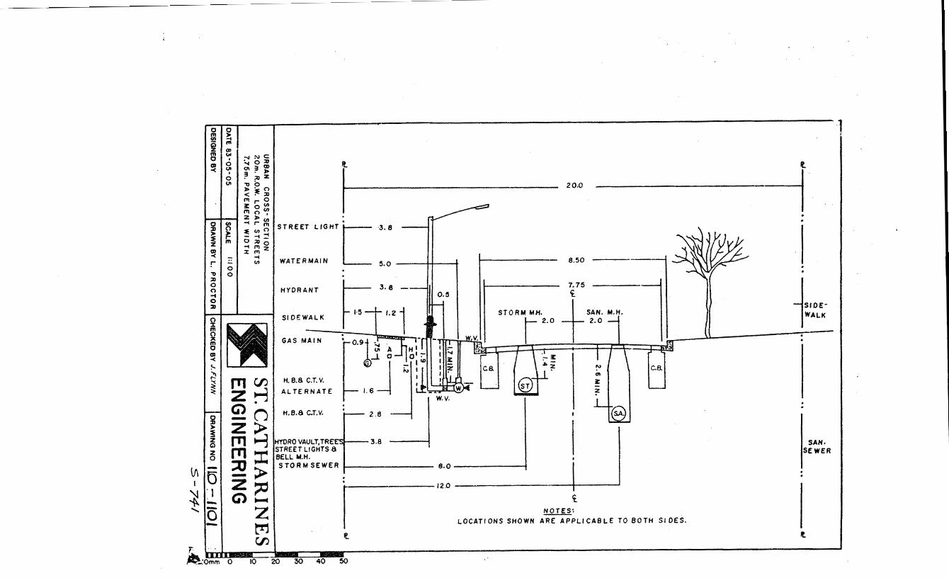
Ll\
0 0 m ~ ~ : m "' 0 • (I) 0 -< U> •
0 U>
g,~
~· ~ z m (I) < r ., ::tl 0 0 -1 0 ::tl
~ ~ IY (I) < !--~ ~ :<:
g >
~ Cl
~
-
0 0
-.JN~ :.... 0 (I) Ql 3 J> ~ ~ z :!:>o <:E::o !TirO ~ 0~ mo, ZJ>(I) -trm =e (I)~ --t_ o::oo '"11Tlz % ITI ....
(I)
f 20.0 ---i
. STREET LIGHT [ ·3.8
WATERMAIN 5.0 ----++---t 8.50
HYDRANT
SIDEWALK
. 3.8
Ul A ...L 0
ITSI--3.8
7.75 ~
STORM MJi. +SAN. M.H. ,2.0 2.0
s.o ---------j -------12.0 ----------1---_j
i NOTES:
c. a
LOCATIONS SHOWN ARE APPLICABLE TO BOTH SIDES.
'····· lWALK
SAN· SEWER
It
~Omm 0 ·- -· -
1 '

0 0 m > (/) -4 (5 m
~ ~ 0 <:) 1%1 (JI -< •
(i)
0 (/) :0 (') )lo > :E rz m ~ ~ t- :-I . (I) 'o .
~ C)
~ ~
0 :J) )lo
:E z Q z 9
-0 I --0
N
~ (I)~ :-.h.~ ~()(!) l;J 1.1) h. '()~~ h.r--n ~-:o ,...~~ ~~1.1) f>)l.l)(l)
~ ..... · ..... ~~ ~::::() i:)"'t"'t ..... 1.1)() ;t ~ ~ --,..
"1<:) =t~
~-C)OI
1.1)~ ~:'ll "19 ~~ t'-() ~~ 1.1),....
Q)~ ,... .
1'11~ zrl ~n
~~ m:t :0~ -~ zloo-4 Glz
M ~
If
I
... t. . .... GAS MAIN 0.9.i 0. ·
@_j_ I I
HYDRO ,9£LL 8 cr.• !.6J t !J HYDRO VAULT a BELL MH.i---2.5
STORM SEWER 6.0
16.0
8.50 -------1
7.75 -------H Q.
2.0 J___ 2.0
ll.
TREES, HYDRO VAULTS a BELL M.H. .
2.5,STHEET LIGHTS, HYDS.,
11 AI.H. 1 1
~ 11. rr i ma '· i9 l'\ 1' 'fil 11
HYD. BH. VALVE
1---3.5 lwATERMAIN
£
2.0 8.0 --------;
SANITARY SEWER 10.0-----------------1
lf\ j N If
NOTE
LOCATIONS SHOWN ARE APPLICABLE TO BOTH SIDES. ll.

0 ({)
a5
UR
BA
N
CR
OS
S-S
EC
TIO
N FO
R
18m
R.O
.W.
CU
L·O
E-S
AC
S
&
LIN
K S
TR
EE
TS
W
ITH
S
IDE
WA
LK
S &
7.75
PA
VE
ME
NT
W
IOT
H.
DA
TE
83~05-05
SC
ALE
I :1
00
DE
SIG
NE
D B
Y
DR
AW
N B
Y
R.L
.GR
EE
N
ST. C
AT
HA
RIN
ES
E
NG
lNE
ER
IN G
DR
AW
ING
NO
I l0
-1 10
3

IN CUT
IN FILL
"'"ra-----1.80 m
r e 0 N
" 'i
I
'I'
:I
J ) .;
W000 FLOAT FINISH
''· ' I . ,, :: . . ,
.·,:'
·.ll;
NOTE' TOOLEO JOINTS OR SAW CUTS MUST BE AT LEAST 1/4 TH£ DEPTH OF THE SLAB.
h---- 50 mm MIN. FINISH WITH EDGING TOOL
PANEL DETAIL
EXPANSION JOINT EDGE OF PANEL
NOTES:
I. THE BOULEVARD ON THE STREET SlOE OF THE WALK SHALL BE GRADED DOWN SO AS TO PROVIDE AOEOUATE SLOPE TO THE CURB OR TOP OF DITCH.
2.AT DRIVEWAY ENTRANCES THE SLOPE OF THE SIDEWALK CAN BE INCREASED TO A MAX. OF 6 %.
3.CONCRETE TO BE 2!) MPo, 325 kQ CEMENT per m3, 6% AIR ENTRAINED.
4.THE SIDEWALK SHALL 8E 12Smm THICK, AND AT COMMERCIAL DRIVEWAYS. WIRE MESH
DATE
SHALL BE INSTALLED.
STANDARD SIDEWALK DETAIL 83. 05· 31 SCALE N.T. S.
DESIGNED BY DRAWN BY J.C.
ST. CATHARINES ENGINEERING
DRAWING. NO.

I , . /S.J ~'" REs/o.e-#r/-1~ , l
/•(; .32-IJ ,c-~ Cd~MP.'I?t'MJ. /-<$
PJ?/VcWAY (;'"An'~At:nt:M/ D~ FJfPAN.Std.V o/dtNr.S ~
/ \ r I --u, ~I I I~ pz , t
curre~? EL~ t4. ORdP CGJ./!8 AT ~ r=/1-~ .. -..,- ,·It .cANFWA>'£Nrlt4Ncu- -............._ ~ ~'=>lEE\.. M~>.."'( e~ oM\Ti'ED IF cuRes
r' ~- ~?J'T_i .. ~ C.ONSIRUC.TED OVER \~ENCHE.S g- • T • . {". 9{ 1-' eACKFILLe.o MORE ·n·'"'~ o,...e: YEAR L 9
.. :z:·~ .3 JJ Pc::tE'IIoU5LY, seE s--r3.., FoR. t)J!.•AtL..
L - z_-1'0 ~-BARS . /8
Cl/R8 AND CUTTER DETAIL..
Ft:JR CURB AAICJ CUTTER
C.:JNTI<:AC£/ON JOI.VT.S TD 8£ ~">< 2." OEGP AA/0 t:IJ.L£0 W/TN NPr POUREO J!J/TthW/IVOJ.IS ,:-n.J.GR FJ.l/SH WIT# THE CONCPFTE .5'J.II?.c"ACE. SPACING ro 8£. /5 Fe£r.
EXPA,VS/(}11./ ./0/NTS rO 8£" ~-/MP~I!"t:N.4TGD .c"/8./?E SOA.ItD MEET/IVG A.$. r.-. .SPEC. /7.5/. oPAt:"/NG
TO 8E /80 ..c"'EET A,t:'PA!OJ('. 0/Z .AG-c>'l..e'ECTEO BY TN£ .£NtNNEGA.
FOR CURB /A/TEG~AL Jf//TN C"NC PAVEMENT
Cl/IZBS To HAVE SAMe' &>/MGIVS'/ONS' W-'TN £)(C.£",.TNN THAT T#E .DePrN ;tT GUTTER SHAL..L. COA/F'I:I.Il!!~ To .OEPTN o.r .:".:JNC.e£7'2' PAVEMENT"..
JO/AIT6 ra BE .P~ACE'.O 60 A6 TO Co/NC/OE
iVIT/.1 ../CIN1'".S '""" CoNC./Z.CTE PAVJ!!".MEA/1'".
l
s-~
~:e:.YtSEO SEP. 6;:_7.3. R. GREE~
CITY OF ST.CATHARINES CfTY ENGINEER'S OFFICE
e·URB AND GC/TTER DETAIL
SCALE v.·e. NOR ToN '"ONE -on--~ .. --'" ~e:-r. .....
DWG; IJO~ -1~9~
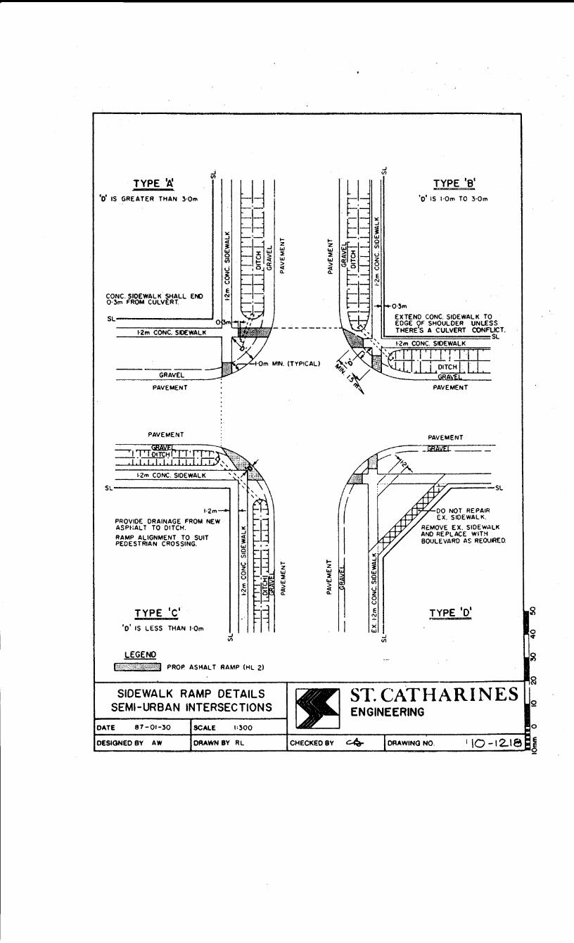
TYPE '11. '0' IS GREATER THAN 3·0m
CONC. SIDEWALK SHALL END 0·3m FROM CULVERT.
GRAVEL
PAVEMENT
PAVEMENT
.J en
1·2m
PROVIDE DRAINAGE FROM NEW ASPHALT TO DITCH.
RAMP ALIGNMENT TO SUIT PEDESTRIAN CROSSING.
TYPE 'c' 'o' IS LESS THAN I·Om
LEGE NO
...1 en
'''''\')'?t::>f:::t?M PROP. AS HALT RAMP (HL 2)
..... z w :::E UJ > <t a.
..... z UJ :::E UJ
~
..... z w :::E w
~
..... z w :::E w
~ 0 ~ u E ~ x w
...1 en
..J en
TYPE '8'
'o' IS I·Om TO 3·0m
0·3m
EXTEND CONC. SIDEWALK TO EDGE OF SHOULDER UNLESS THERE'S A CULVERT CONFLICT.
. SL
PAVEMENT
PAVEMENT
REMOVE EX. SIDEWALK AND REPLACE WITH BOULEVARD AS REOUIAED.
TYPE '0'
~----------------------~----------------------------,£ ST. CATHARINES SIDEWALK RAMP DETAILS
SEMI-URBAN INTERSECTIONS
DATE 87-01-30 SCAlE 1:300
DESIGNED 8Y AW DRAWN 8Y RL
Q ENGINEERING
0
DRAWING NO. I \0-12..\8 !
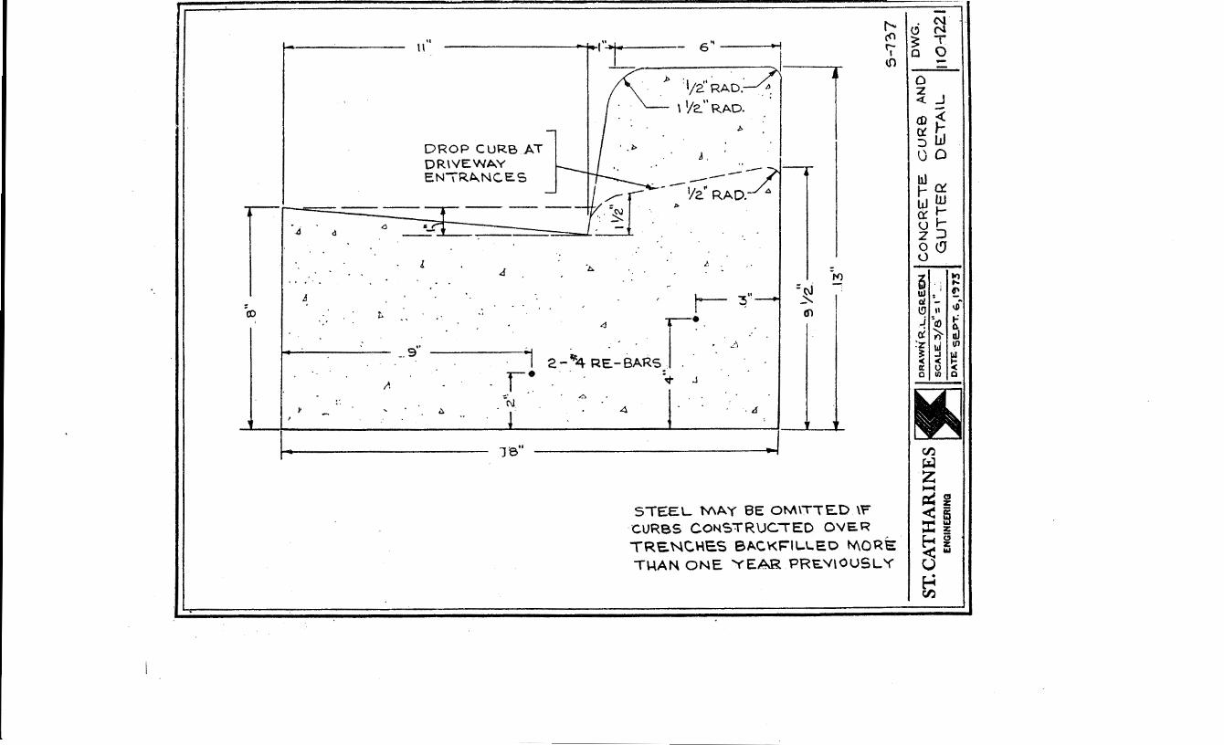
, . .,..._ __
__
-a" ----...-~~~
• '
1---
----
----
----
--""
t.
.
l ..
'•
I ~
! . \D~
=
e- :
....J
~z'\1
())~
·-~·
.1 I
I
\1
\ N:\
,_
;o
\ ..
~
CJ
\ :
·~
'!>
-•
.(}I
( .t
t II
_
J ~-----
9 'lz.-
----
--..
1
~--.J3"---
5-1
37
ST
.CA
TH
AR
INE
S ~ O
RAWN.R
;~:GR.
.~\tN
'CO
NC
RE
TE
C
UR
B
AN
D
OW
G.
EN
GIN
E£R
IHQ
S
CA
LE
...;
:)/S
-: I
-.
. G
UT
TE
R
0 E
.TA
\L
110-
1221
D
AT
E S
e..
PT
. E
-,1
.,7
3
I

/. ,.:-ou.N.OA;-10# MA'IY 1WST #QT !U CO¥N~CTE'll i"' SANITAI?Y SEWER.
2 L)f.SCIIARG£ OVTiET SJfCI/i./) ecAT FRONT" 0.1? .Rl'llR OF t:JWELfi.Yt:.
,3 . .DISCHARGE OC!rt.ET S#OUt.L>BE AT L E ASr .¥ .rr. FA"'M t"'UNA-!TICW WAU.
4. IF A,PP~OV£1) BY CITY EAICIIIEU TN£ L)/SCirARG£ OUTLET IHA'I BE /Nt:JI~ECT.t Y COAINEC/EL> r-o S7'0~M SEW£~.
SPLASH PAl)
-r¢ FOOIYt:JAJ"ION .DRAIN
_NOTE; :5L-OT 1"-l c.c:NEA FOR 6E2.VJGE. PIPE. I PUMP • ""-SO TO
'------.· AU..OW F~ CAJE.fZ.FL..OW
CETAIL. ~· (IJT'S\
FOUNDATION DRAIN CONNECTION
DATE M~.I'\C\c:)ISCALE H.'t$.
DESIGNED BY k.R DAAWN BY O.T.S.
TO STORM
ALTEifWATIVE CONNECTION
TO STO.f>M S.!'WER
COVER (SEE DE TAlL-'A')
LEVEL AT WHICH P<.IMP IS ACTIVATED
ST. CATHARINES
DAAWINGNO. II0-1Z2Z
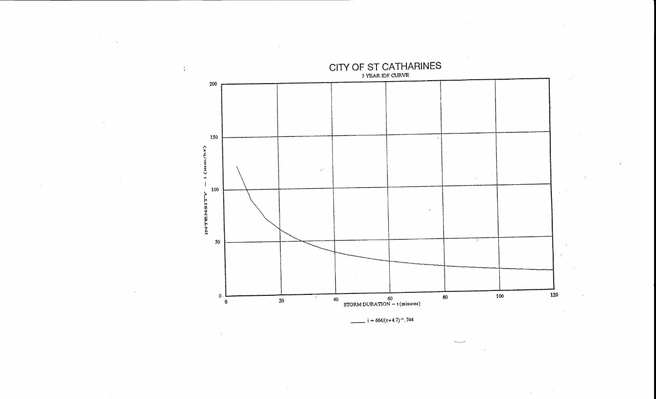
t'l k .1: ' E e v
I
200
150
~ 100
... ttl
~ ('<
z ... 50
0 0
CITY OF ST CATHARINES 5 YEAR IDF CURVE
\ ~ ~ ~
j----_J
20 40 60 STORM DURATION- t(minuces)
so 100 120
-- i =664/(t+4.7)".744


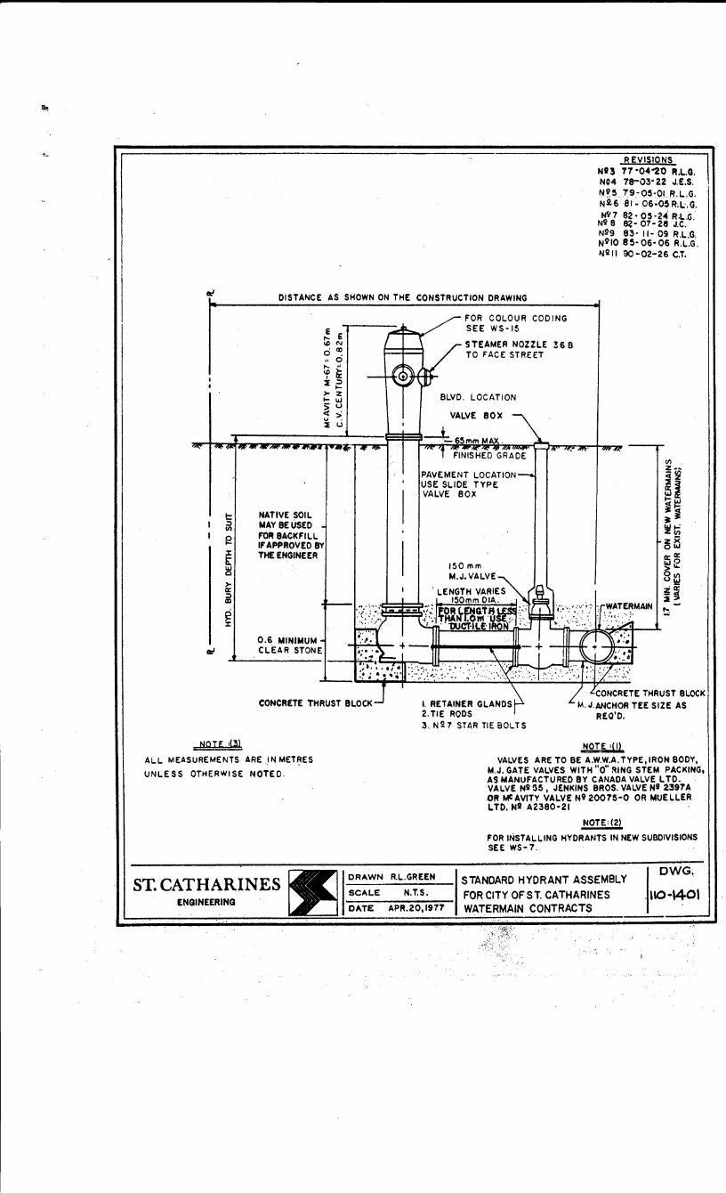
REVISIONS Nf3 11 ·04"20 R.L.G. N04 78-03• 22 J.E.S. N~5 79-Q5~01 R.L.G. N26 81- 06·05R.L.G. N~7 82· 05·24 R.L.G.
Ni 8 8?- 07· 28 J.C. Nl19 83· II- 09 R.L.G. N9IO 8 5- 06· 06 R.L.G. N211 90·02-26 C.T.
DISTANCE AS SHOWN ON THE CONSTRUCTION DRAWING
t: ~ If)
f2
t w 0
>-a: ~ Cll
g :I:
ef
NATIVE SOIL MAYBE USED F'OR BACKFILL
!. e !DN
'(I) 0 . " 0 t-- " 'f i'r ~ ~ .... >- z .._ IU > u < ' u >, ~ u
IF APPROVED 8Y THE ENGINEER
0.6 MINIMUM CLEAR STONE
FOR COLOUR COOING SEE WS-15
STEAMER NOZZLE ~6 B TO FACE STREET
PAVEMENT LOCATION USE SLIDE TYPE VALVE BOX
If)
z" <i~
~~ ~~ ~ ~
~Iii zx OIU a:: a: ~:? Olf) u\!1 z:a:: i! ~
CONCRETE THRUST BLOCK I. RETAINER GLANDS CONCRETE THRUST BLOCK
M.J.ANCHOR TEE SIZE AS REO'D.
NOTE :(3)
ALL MEASUREMENTS ARE .IN MET~ES
UNLESS OTHERWISE NOTED.
ST. CATHARINES ENGINEERING
2. TIE RODS 3.N27 STARTIEBOLTS
OR-'WN R.L.GREEN
SC-'LE N.T.S.
DATE APR.20,1977
NOTE :(1)
VALVES ARE TO BE A.W.W.A.TYPE,IROttBODY, M.J. GATE VALVES WITH "o" ~lNG STEM PACKING. AS MANUFACTURED BY CANADA VALVE L TO. VALVE Nil 55, JENKINS BROS. VALVE Ni 2397~ .OR MCAVITY VALVE N9 20075-0 OR MUELLER LTD. N2 A2380·21
NOTE:(2)
FOR INSTALLING HYDRANTS IN NEW SUBDIVISIONS SEE WS-7.
STANDARD HYDRANT ASSEMBLY FOR CITY OFST. CATHARINE$ WATERMAIN CONTRACTS
DWG;

((OAOWAY
No-t E.:
VALVeS ARE NO""T 10 6E. C.L.oSE:.R 1\-\P.N ;',-o f<...
1~-<+' cot-.~c. w A.L...J.<
· ST. CATHARINES ENGINEERING
1-~ awr .J cd· QL 4 .• ~ ~&? ~ ' :tirL
\) ow % w u~ 0 u ~ )'UJ ~
-~ <!. Jr D d)v'l
L.~ 4 w~ r lflr Ul ~ 3
~
51'ANC>t>.R.D WATE RMAIN - LOCATICN
REVISED 2-4-76 R.L.G.
DRAWN R.L.G.R~EN'I S'TP..NDARD L-OCAT.ION F'OR " • I WA'TE.RMP..INS ¢ H'<DRA.NT
SCALE I t I O • 0 ' . AT I N "T E. R SECT I 0 N S DATEAP~. 5
119"'14 \N\"T'r\ A '3CS'CuRB RAD\\
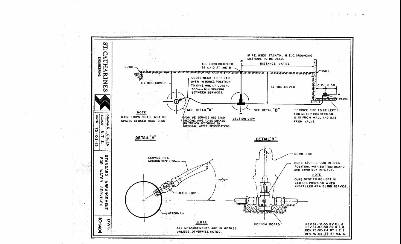
CJ'J rl (j
i~ ~::r: ~;> i~ .....
z ~ CJ'J
elm 0 > 0 :u .... )o )o fll I ~ Ill z .._, :u Ul z r I .
G) 0 -i ::u N f1l I (J) f1l (;i' z
(J) "'11-i Ol> ::Uz
0 ~)> l>::u -io f1l ~ )>
::u (J):xJ f'l)> ::uz <G> -m 03: mm (J)z
-i
-0 0
~ =E G)
CURB
GOOSE·NECK OVER IN HORIZ. POSITION TO GIVE MIN. I. 7 COVER.
--w-~j'Asn. DETAIL"A"
MAIN STOPS SHALL NOT BE FOR PE SERVICE USE SAND ~ 4 SPACED CLOSER THAN 0. 50 BEDDING. PIPE TO BE SNAKED
DETAIL'. A"
SERVICE PIPE MINIMUM SIZE= 20m m
IN TRENCH ACCORDING TO GENERAL WATER SPECIFICATIONS.
22Yl 0
Jl'
NOTE =
If PE. USED ST.CATH. H. E. C. GROUNDING METHODS TO BE USED.
DISTANCE VARIES
1.7 MIN .. COVER
(i\ ,!:.L~.~:ALVE ~SEE DETAIL"8"'
;& SERVICE PIPE TO BE LEFT FOR METER CONNECTION·. 0.15 FROM WALL AND 0.15 FROM VALVE.
SECTION VIEW
DETAIL'S''
,rd:::~~ CURB BOX
·11:-~ I• I
1 II I AND CURB BOX IN PLACE.
( Jl CURB STOP· SHOWN IN OPEN I l1 v POSITION, WITH BOTTOM BOARD
) NOTE
\ t I CURB STOP TO BE LEFT IN
BOTTOM BOARD
CLOSED POSITION WHEN INSTALLED ASA BLIND SERVICE.
ALL MEASUREMENTS ARE IN METRES UNLESS OTHERWISE NOTED ..
REV.SI-10-05 BY R.L.G. REV.SI-06-08 B:Y R. L.G. REV. 78-02-24 BY J. E. S. REV.76,0e-~;> BY R.L.G.

WATERMAIN
CURB BOX
MUELLER H-10400 EMCO 16300
50 mm VALVE 8' ORA IN
MUELLER H-10291 ORISEAL EMCO 21084 CENTURY ,. 1.0 MIN. 'I
M.J.CAP OR PLUG TO
BE TIE ROOOEO WITH 20mm ROO & SUITABLE
DRILL 8 TAP TO 50mm BRASS NIPPLE SIZE.
M.J.CAPOR PLUG
BELL CLAMP,·
50 mm GALVANIZED PIPE CAP
.,.----t- LENGTH AS REQUIRED.
CONC. THRUST BLOCK
WOOD OR BRICK
NOTES:
1.) IN CASES WHERE THE BLOW-OFF CAP IS LOCATED 'IN A DRIVE WAY, SIDEWALK, PEDESTRIAN ACCESS OR OTHER HARD SURF.6CE AREA, THE GALV. PIPE CAP SHALL BE FLUSH WITH GRADE, WITH EXPANSION MATL. SUPPLIED AROUND THE PIPE.
2.) ALL MEASUREMENTS ARE IN METRES UNLESS OTHERWISE NOTED.
REV. 81·06·05 BY R.L..G. REV. 79-03·02 BY R.l..G.
ST. CATHARINES oRA.wN R.L.GREEN STANDARD 50 mm DWG.
ENGINEERING _s_cA_L_E_N_._T._s_. _.BLOW-OFF ASSEMBLY OAT£ 78·05·01
ll0-140.5

REVISION N2 I REVISION NO 2 REVISION N93 REVISION N24 REVISION N!l5
5.0 (20m R.O.W.l 4.5 (18m R.Q.W.) 3.5 ( 16m R.Q.W.)
"---------3-.8--:-(-20-:m-R-:.0-.W-:.l---:_:_ 1.2 (20mR.O.W.) ~ 3. 5 ( IBmR.O.W.) I. 0 (18m R.O.W.) 2. 5 ( 16m ~~.O~.W.:.:..:..!.l:...._ ______ o.l-o----.:..:1....:::0:._(,_1:...::6'-'-m"-'-'R.:..:.O:o:..W~.)-
FOR COLOUR CODING 1
1-5 C/)
0 1-
~ a. w 0 )o
Q; :::> <D
0 > ::z::
--
NAllV£ SOIL MAY BE USED FOR BAO<FI L L IF APPROVED S'f THE ENGINEER
0.6 MINIMUM CLEAR STONE
SEE WS-15. I STEAMER NOZZLE 36 8 TO FACE STREET
BLVD. LOCATION VALVE BOX
150mm VALVE
lENGTH VA ROE\
~~~:,·I~ .3~:m:.~.::~.~t~>~~' CX.JCT I L E IRON
l i~
> 0 (J
z ::::E
" ...:
CONCRETE THRUST BLOCK I. RETAINING GLANDS 2.TIE RODS
CONCRETE THRUST BL.OCK M.J. ANCHOR TEE SIZE AS REO'D.
ST. CATHARINES DRAWN R.LGREEN
SCALE N.T.S. ENGINEERING
DATE 73-04-20
NOTE!II
VALVES ARE TO BE A.W.W. A. TYPE, IRON BODY GATE VALVES WITH "o" RING STEM PACKING. ~S MANUFACTURED BY CANADA VALVE LTD., VALVE •.
N2 55, JENKINS BROS. VALVE N.Q 2397A OR MCAV.IJ'Y
N2 20075-0, OR MUELLER L TO. NQ A2380-·2!
NOT£(2) ALL MEASUREMENTS ARE IN METRES UNLESS OTHERWISE NOTED.
STANDARD HYDRANT ASSEMa.Y FOR NEW SUBDIVISIONS.
'

u
l_ 4' CO"-!C WAL 1-<
ft.-- - -------
_N ~::y~_:_ b.L.I... VA.LYE.S AP.E.\C f?,E 1-A.ID u?POS11E. \HE R_.
ST. CATHARINES DRAWN R.I... GREE-N
ENGINEERING
u 7 0 u -~
P.()hf>V.//>..,Y
d J a: ~
I q-1
N 0 ILl (/)
5 ILl Q::
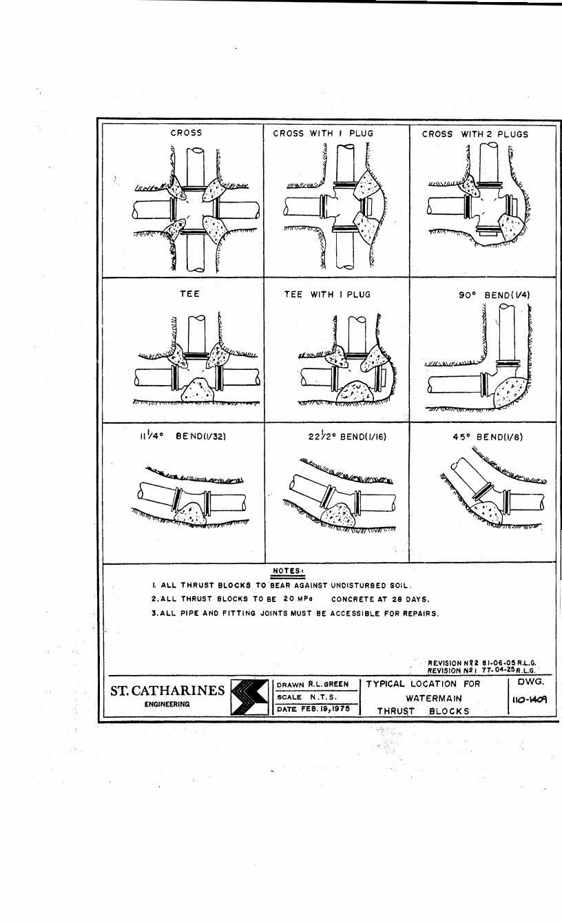
CROSS CROSS WITH PLUG CROSS WITH 2 PLUGS
TEE TEE WITH I PLUG 90° 8 END ( V4)
II ~4° BE-NO(I/32) 22ho BENO(I/16)
NOTES1
I. AL.L THRUST BLOCKS TO 'BEAR AGAINST UNDISTURBED SOIL.
2.ALL THRUST BLOCKS TO BE 20.MPo CONCRETE AT 28 DAYS.
3,ALL PIPE AND FITTING JOINTS MUST BE ACCESSIBLE FOR REPAIRS.
ST. CATHARINES ENGINEERING
DRAWN R.L.GREEN
SCALE N .T. S.
PATE FEB.I9,197!S
· RENISION NU 81·06·05 R.L.G. EVISION 1'11~ I 77· 04·25 R
TYPICAL LOCATION FOR DWG.
WATERMAit~ 110-~ TH T LOCKS
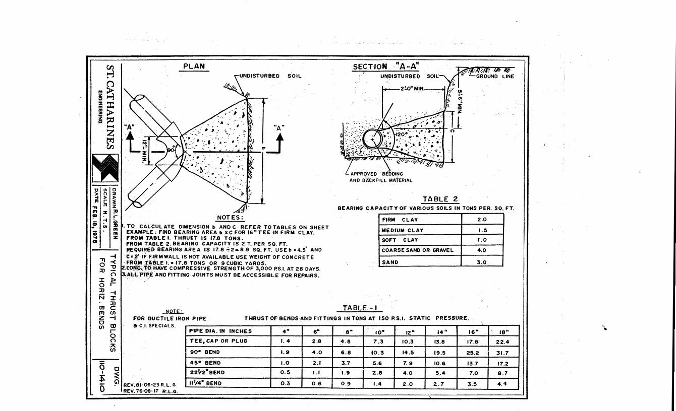
CJ)
rl 0
~~ ~::I: l!> ~~ ~
z ~ ~
r Q ::0
"' "' z I
.,-t 0 -< ::0 "'0
0 :I: )> 0 r ::0 -t N ::z:.
::0 m c IT) (f)
PLAN SOIL
.. A ..
' , ... _ .. T ~J
I. TO CALCULATE DIMENSION b AND C REFER TO TABLES ON SHEET EXA.MPLE: FINO BEARING AREA b ,XC FOR 16" TEE IN FIRM CLAY. FROM TABLE I. THRUST IS 17.8 TONS. FROM TABLE 2. BEARING CAPACITY IS 2 T. PER SO. FT. REQUIRED BEARING AREA IS 17.8 ~2= 8.9 SO. FT. USE b :4.5' AND t•2' iF FIRMWALL IS NOT AVAILABLE USE WEIGHT OF CONCRETE
·FROM ,J~BLE I. a 17.8 TONS OR 9 CUBIC YARDS. .COI'(~.)f(i HAVE COMPRESSIVE STRENGTH OF 3,000 P.S.t AT 28 DAYS.
~~l.;L PI~,E AND FITTING JOINTS MUST BE ACCESSIBLE FOR REPAIRS.
...11QIL
SECTION nA .. A11
U~DISTURBEO
TABLE 2 BEARING CAPAC.ITY OF VARIOUS SOILS IN TONS PER. SO. FT.
FIRM CLAY 2.0
MEDIUM CLAY 1.5
SOFT CLAY 1.0
COARSE SAND OR GRAVEL 4.0
SAND 3.0
TABLE-t z -t FOR DUCTILE IRON PIPE THRUST OF BENDS AND FITTINGS IN TONS AT 150 P.S.I. STATIC PRESSURE. 0 m (f)
r 0
a C.l. SPECIALS. 4" 14" 16"' - 18" 6" 8" 10" 12" PIPE DIA. IN INCHES
0 ·A
1.4 2.8 _4.8 7.3 10.3 13.8 17.8 22.4 TEE, CAP OR PLUG
(f) 90° BEND 1.9 4.0 6.8 10.3 14.5 19.5 25.2 31.7
1.0 2.1 3.7 5.6 7.9 10.6 13.7 17.2
0.5 1.1 1.9 2..8 4.0 5 . .4 7.0 8.7
0.3 0.6 0.9 1.4 2.0 2..7 3.5 4.4
45° BEND 0 I
~
0
0 ~ G'>r . • REV.81·06·23 R. L. G.
REV. 76.08·17
22lf2°BEND
111/4° BEND
I I I ..

t-1ETRIC APARTMENT SIZE OF
SIZE SERVICE
3 TO 4 SUITES 25 mm
5 TO 9 SUITES 40 mm
10 TO 14 SUITES 40 mm
15 TO 24 SUITES 50 mm
25 TO 30 SUITES 50 mm
31 TO 40 SUITES 100 mm
41 TO 60 SUITES 100 mm
61 TO 80 SUITES 150 mm
81 TO 200 SUITES 150 mm
200 AND OVER
IMPERIAL AVERAGE USAGE:
t-1ETRIC AVERAGE USAGE:
ST. CATHARINES ENGINEERING
200 mm
~ALLON/MINUTE/SUITE
1.13 L/MINUTE/SUITE
DRAWN R.L.GREEN SCALE
DATE;. 31-3-76
IMPERIAL SIZE OF SERVICE ~
1" 5/8
1~" 1"
1~" 1"
2" 1"
2" 1"
4" 1~"
4" 2"
6" 3" COMP. '
6" 3" COMP.
8 .. 4" COMP. ( MIN,.)
(ESTIMATED - BASED ON METER READING FACT)
REV. R.L.G. 81'·06·22
RECOMMENDED SERVICE AND METER SIZE FOR
APARTMENTS
DWG.
110·1412

CLASS 'B' BEDDING UNDER BOULEVARDS
a: w > 0 u
NATIVE SOIL MAY BE USED -~--tFOR BACKFILL IF APPROVED
BY THE ENGINEER. COMPACT
GRAN:'A" MATERIAL TO
SPRING LINE OF PIPE.
::i ;l
~
CLASS 'B' BEDDING
TO 95% OF MAX. CRY DENSITY.
BACKFILL TO BE COMPACTED IN 150mm LAYERS.
DUCTILE IRON OR PVC WATERMAIN
IOOmm LEVELING COURSE OF SELECT GRANULAR MATERIAL
UNDER PAVEMENT AND SHOULDERS
NOTE• ALL MEASUREMENTS ARE IN METRES -- UNLESS OTHERWISE NOTED.
TYPICAL WATERMAIN BEOOING ANO BACKFILLING
DATE 81-09-17 SCALE N.T. S.
DESIGNED BY R. GREEN DRAWN BY R. LOGAN
DUCTILE IRON OR PVC WATERMAIN
IOOmm LEVELING COURSE OF SELECT GRANULAR MATERIAL
Q
0
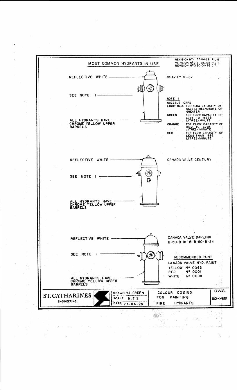
MOST COMMON HYDRANTS IN USE REVI$10NN~I 77·04·26 RL.G l:lf JISIO"' N\?2 81·06·08 P L G REVISION N23 90·01· 26 C.T
REFLECTIVE WHITE----
SEE NOTE
ALL HYDRANTS HAVE --CHROME YELLOW UPPER 8ARRELS .
SEE NOTE I --------
ALL HYDRANTS HAVE ---CHROME YELLOW UPPER BARRELS
REFLECTIVE WHITE
SEE NOTE
ALL HYDRANTS HAVE---CHROME YELLOW UPPER BARRELS.
ST. CATHARlNES £NGINEERINQ.
DRAWN R.L.GREEN
·scALE N. T. S.
OATEj 77-04-26
MC AVITY M-67
NOTE I
NOZZELE CAPS LIGHT BLUE FOR FLOW CAPACITY OF
5678 LITRES/MINUTE OR GREATER
GREEN FOR FLOW CAPACITY C'F 3785 TO 5678 LITRES/MINliTE
ORANG£ FOR FLOW CAPACITY OF 1892 TO .H8~ LITRES/ MINUTE
REO FOR FLOW CAPACITY OF LESS THAN 1892 LITRES/MINUTE
CANADA VALVE CENTURY
CANADA VALVE DARLING 8·50·8·18 ·& 8·50·8·24
RECOMMENDED PAINT
CA ~JADA VALVE HYD. PAINT
YELLOW NM 0063 REO N'i 0001 WHITE NJI 0008
COLOUR CO DING OWG.
110-~JS FOR PAINTING
. FIRE HYDRANTS
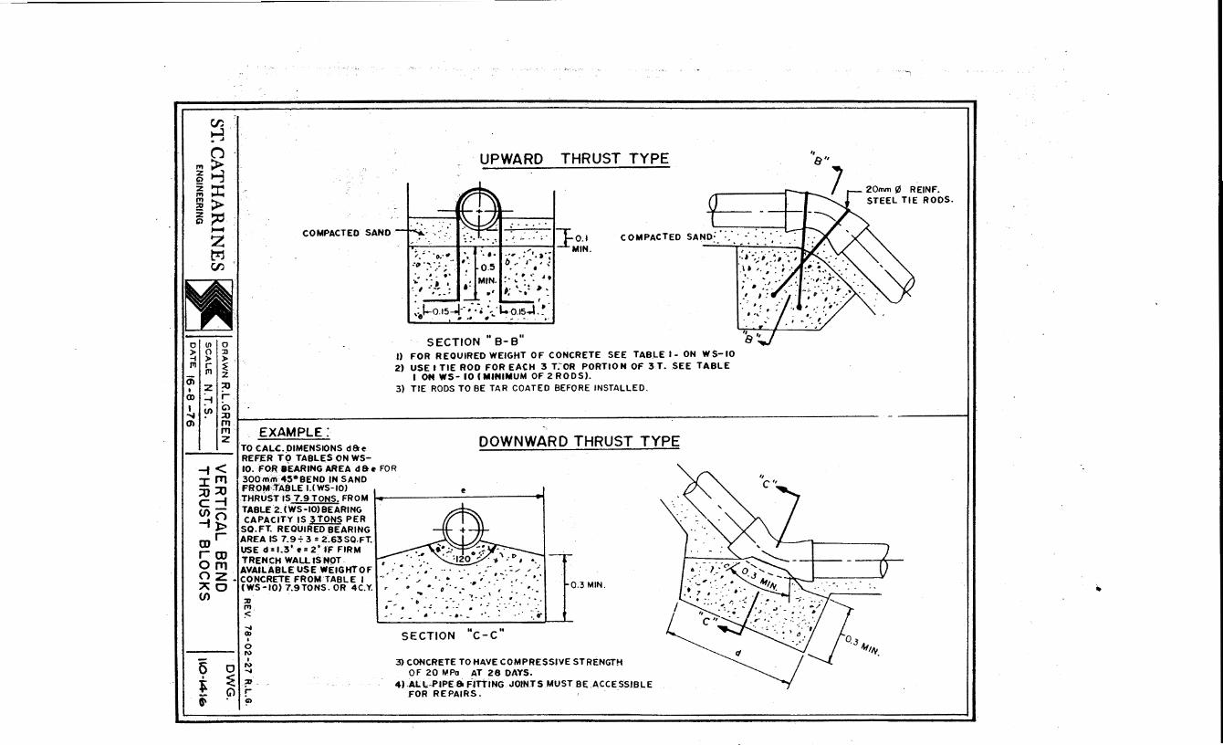
~.
rl (J
"'~ ~1-j ~:I: 2> ~ :;c.
0
~ f!l
m I (l)
,.... z tr1 r:J)
(ll
0 > r f!l
z :-f
0 :n )>,
~ z ::0 r Gl
COMPACTED SAND
UPWARD THRUST TYPE
. ;~ ·,.·.: '·fk,o.• COMPACTED SAND:.::. •· : · .•. · .. .. ...... -' .
.• , .:'•.,·; MIN. tJ •• I' , ~ . . . ~· : ': .. : ~. ,. ' "! ~-. ... . .
·---·-' .~f.-o.1s-l··; .-. ·-~·l..o.ts..l. ~ ·
\ # ., • . ... - ..••
SECTION "B-B" I) FOR REOUIRED WEIGHT OF CONCRETE SEE TABLE 1- ON WS-10 2) USE I TIE ROO FOR EACH 3 T;OR PORTION OF 3 T. SEE TABLE
I ON WS- 10 (MINIMUM OF 2 RODS). 3) TIE RODS TO BE TAR COATED BEFORE INSTALLED.
20mm 0 REINF. STEEL TIE RODS.
.!., (/) 0> ::0 ~----------------------------------------------------~--------------------------1'11
1'11 z. EXAMPLE:
TO CALC. DIMENSIONS d& ~ REFER TO TABLES ON WS-
DOWNWARD THRUST TYPE
-f < 10. FO.R BEARING AREA d&e FOR I f'l1 30Qmm 45°8ENO IN SAND ::u ;u FROM·~tAfJLE I.(WS-10) I ~ ~I C -f THRUST IS 7.9 TONS. FROM• ., (/) O TABLE 2.(WS-10)8EARING
-1 l> scC:.~~c~E"o~R3E~0::A~~:G CD r AREA IS 7.9 + 3 : 2.63 SQ.FT:
USE d:l.3'e=2'1'F FIRM
Or OJ TRENCH WALLISNOT fT1 AVAILABLE USE WEIGHT OF
(') Z ·CONCRETE FROM TABLE I ,.. • · A 0 (W.S-10) 7.9TONS. OR 4C.Y.
. -/ /
' . ... ,. ..... , .. \ . .. .. . ... D ... .... \ I ...
0.3 MIN. (/)
5 0
t ~ G)
i'
:0
"' :< ~ (II
• 0 1\)
I 1\) ~
?'· : G)
',.,.. 0-.:. ·:·~--- :·:·: ... • .
.. - ••• -·-- 4. :~;,.
SECTION "c-c"
3) CONCRETE TO HAVE COMPRESSIVE STRENGTH OF 20 MPo AT 28 DAYS.
4).ALL-PIPE 8i FITTING JOIN.TS MUST BE .ACCESSIBLE FOR REPAIRS. .
~
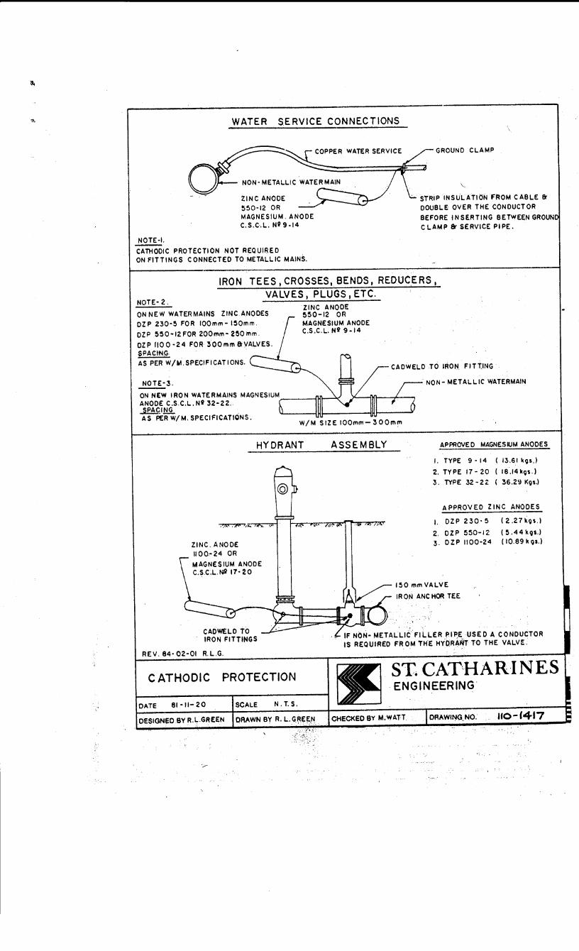
WATER SERVICE CONNECTIONS
COPPER WATER SERVICE GROUND CLAMP
NOTE-I.
ZINC ANODE 550·12 OR MAGNESIUM. ANODE C.S.C.L. N!? 9-14
CATHODIC PROTECTION NOT REQUIRED ON FITTINGS CONNECTED TO METALLIC MAINS.
\ ..
STRIP INSULATION FROM CABLE & DOUBLE OVER THE CONDUCTOR
BEFORE INSERTING BETWEEN GROUN CLAMP & SERVICE PIPE.
NOTE-2.
IRON TEES,CROSSES,BENDS, REDUCERS, VALVES I PLUGS I ETC.
ON NEW WATER MAINS ZINC. ANODES DZP 230·5 FOR IOOmm- 150mm.
DZP 550-12 FOR 200mm- 250 mm.
DZP flO 0 ·24 FOR 300mm &VALVES. SPACtNG AS PER W/M.SPECIFICATIONS.
NOTE-3.
ZINC ANODE 550-12 OR MAGNESIUM ANODE C.S.C.L. Ni 9-14
CADWELO TO IRON FITT,ING
NON- METALLIC WATERMAIN
ON NEW IRON WATERMAINS MAGNESIUM>----...fl.D.---''< ANODE C.S.C.L.Ni 32-22. SPA<;I,llit AS PER W/M. SPECIFICATIONS.
W/M SIZE 100mm-300mm
HYDRANT
ZINC. ANODE 1100.-24 OR
MAGNESIUM ANODE C.S.C.L. N2 17· 2 0
CADWELD TO IRON FITTINGS
REV. 84· 02-01 R.L.G.
CATHODIC PROTECTION
DATE 81 ·II- 20 SCALE N. T. S.
DESIGNED BY R.L.GREEN DRAWN BY R. L. GREEN
ASSEMBLY APPROVED MAGNESIUM ANODES
I. TYPE 9 • 14 ( 13.61 k9s.l
2. TYPE 17-20 ( 16.14kQs.)
3. TYPE 32-2 Z ( 36.29 Kgs.)
APPROVED ZINC ANODES
1. DZP 230·5 (2.27kos.l
2. OZP 550-12 (5.44kos.) 3. DZP 1100·24 (10.69kos.)
- IF NON· METALLIC FILLER PI~E USED A CONDUCTOR IS REQUIRED FROM THE HY0:RAtlT TO THE VALVE.
ST. CAT'HARINES ENGINEERING.
DRAWING_ NO. uo-1417

UNDER FOOTING INSTALLATION THROUGH WALL INSTALLATION
I 250tnm MIN. WHEN METER TO BE INSTAI.I.ED & 150mm IF NO METER.
TURNBUCKLE
FLANGED TO PLAIN END STAND· PIPE.
FOOTING
50tnm x 500tnm ANGI.E IRON BOTH SIDES
16mm TIE RODS ON IOOmtn I.INES
2 Otntn TIE RODS ON 150tntn OR LARGER SERVICES.
RODOED BOTH SlOES.
co)~c,THRusr BLOCK AS ::~tR WS· 16
FLANGED WATERMAIN
TYPICAL SERVICE ENTRANCES FOR IOOmm TO 300mm SERVICES
ST. CATHARINES ENGINEERING
DATE 81·08·06 SCALE N. T. 5.
DESIGNED 8YR.L.GRE£N DRAWN BY R.L.GREEN
Q
0
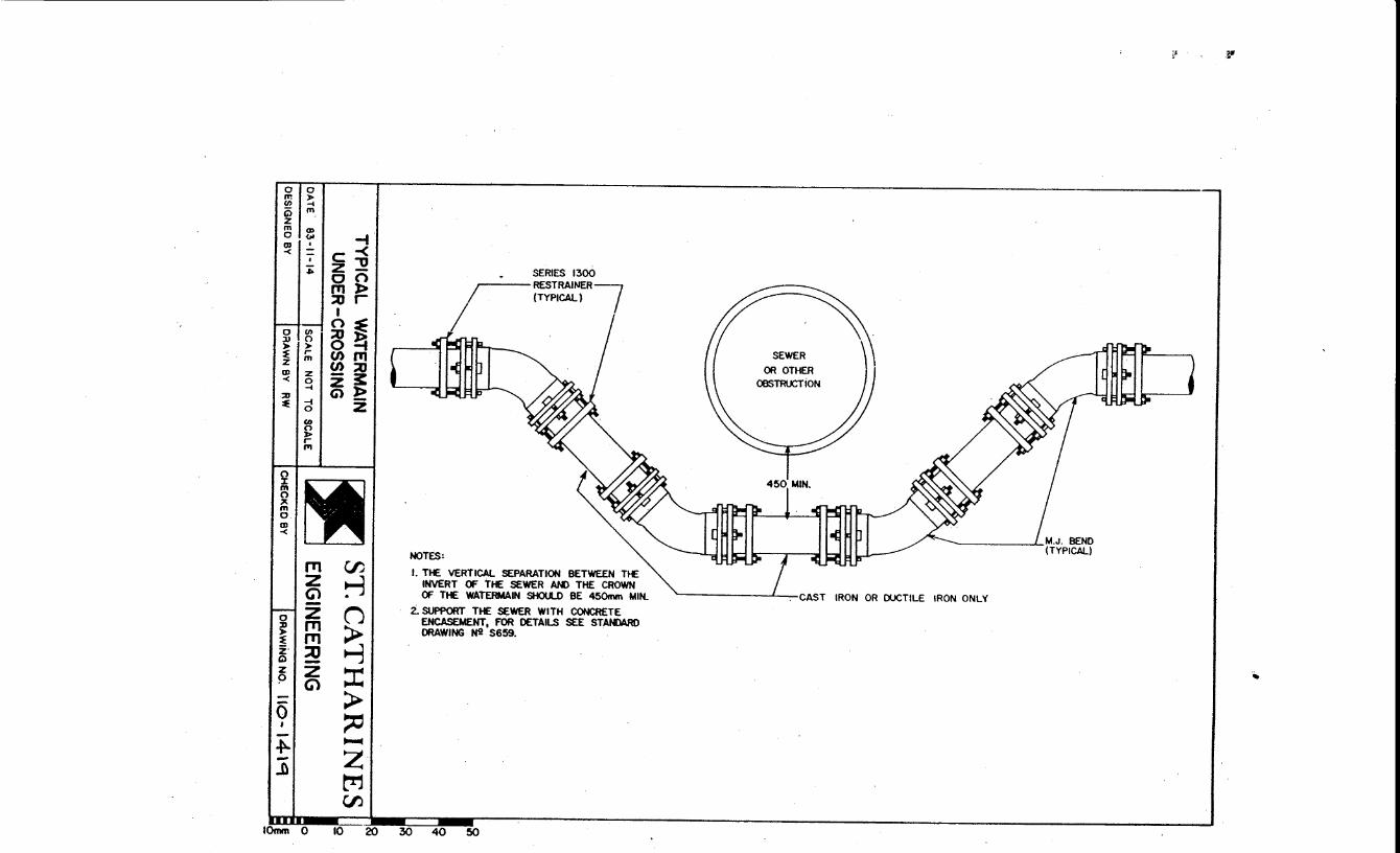
0 0 m > C/) .... i5 m z m Q)
0 ~I -i ~~~ c-< - z -o • 0 0
f'Tl)> :or I
gl~. £ ~ ~ ~ ~~I IJJ z ~ :0 -< 0 z 3: ;u .... Gll> ::e -i -
g > ~ z· Q
~
0 ' + -..D
0 z ~ r
"'
en ~ C1
~ ::I: > ~ ....... z M f'J)
c:= IOmm 0 10 20
. SERIES 1300
(TYPICAL) ~r€SCRMN£R~
u~~rl_~ I
NOTES:
I. THE VERTICAL SEPARATION BETWEEN THE INVERT OF THE SEWER AM> THE CROWN Of THE WATERMAIN SHOULD BE 450mm MIN.
i. SUPPORT THE SEWER WITH CONCRETE ENCASEMENT, FOR DETAILS SEE STANDARO DRAWING N2 S659.
30 40 50
i} ~
( ( SEWER
OR OTHER OBSTRUCTiON
~-------'---CAST IRON OR DUCTILE IRON ONLY
-~