Engineering Specification Doorbell 6
27
AEOTEC Engineering Specification Page 1 / 27 Engineering Specification Doorbell 6 Document No. SPEC-ZW162 Version 8 Description This document mainly introduces AEOTEC new generation Doorbell 6. The content mainly includes its appearance, features, certifications, quick start, and software function definition. Doorbell 6 is a smart doorbell based on Z-Wave and 433.92MHz/FSK. Not only a doorbell, but also can be used as a siren via setting its modes. Supports pairing with 3 Buttons and can be controlled by 3 Buttons separately. Built-in multiple tones, up to 30. Designed as Multi Channel Device, including 1 Browse Endpoint, 3 Remote Endpoints, 2 Siren Endpoints, and 1 Instant Endpoint, which enhances its application scenarios. Written By Hiking Chou Date 2018-11-14 Reviewed By Date Approved By Date
Transcript of Engineering Specification Doorbell 6
AEOTEC Engineering Specification
Page 1 / 27
Engineering Specification
Doorbell 6
Document No. SPEC-ZW162
Version 8
Description This document mainly introduces AEOTEC new generation Doorbell 6. The content mainly includes its appearance, features, certifications, quick start, and software function definition. Doorbell 6 is a smart doorbell based on Z-Wave and 433.92MHz/FSK. Not only a doorbell, but also can be used as a siren via setting its modes. Supports pairing with 3 Buttons and can be controlled by 3 Buttons separately. Built-in multiple tones, up to 30. Designed as Multi Channel Device, including 1 Browse Endpoint, 3 Remote Endpoints, 2 Siren
Endpoints, and 1 Instant Endpoint, which e nhances its application scenarios.
Written By Hiking Chou
Date 2018-11-14
Reviewed By
Date
Approved By
Date

AEOTEC Engineering Specification
Page 2 / 27
REVISION RECORD
Doc. Rev Date By Pages affected Brief description of changes
1 2018.10.26 Hiking ALL First revision
2 2018.10.29 Hiking 1, 19 Section 1.1 Abstract: add description about security requirement and non-battery operated nodes within the network wil l act as repeaters .
Add new Section 1.4 Quick start. Section 4.15 Configuration: modify the description of the value (0) about
Play Control of Parameter 0x02/0x03, changing to “Set but not play”
3 2018.11.01 Hiking 18,19,20 22
Modify the default Tone Index of Parameter 0x02~0x08 Parameter 0xFF: Add the precondition of ONLY reset to factory default
setting, and the precondition is “ If Size=1, Default=1, Value=0 ”
4 2018.11.05 Hiking All Move the Abstract info to the Home Page’s Description. Add new Chapter 1 TERMINOLOGY DEFINITION Add new Chapter 4 PRODUCT QUICK START, including
How to add Chime into Z-Wave network How to remove Chime from Z-Wave network How to factory reset Chime How to factory reset Button How to install Chime How to install Button How to pair Button How to unpair Button
Modify the process description about pairing and unpairing Button.
5 2018.11.06 Hiking All Section 4.2: add description about security requirement and non-battery operated nodes within the network will act as repeaters .
Modified some spelling and expression mistake. Add hyperlinks to facil itate quick jumps Modify “Keep the previous configuration” of Configuration Parameter
0x02/0x03, changing to “Use last valid configuration”
6 2018.11.07 Hiking 1 5 6 7 27
Home Page: Add “Approved by” Chapter 1: Add the definition of “Ring Button” Chapter 2: Update the picture Chapter 3: Add “Indicator Light Power”, ”Tone Group Customization” Add new Chapter 6 SAFETY CERTIFICATION
7 2018.11.08 Hiking All Modify Directory Outline Merge features and safety certification into the same Chapter Separate the appearance of the product as a page
8 2018.11.14 Hiking Home Page Modify the encoding format of “Document No.” in Home Page, changing to “SPEC-Product Model”

AEOTEC Engineering Specification
Page 3 / 27
Table of Content
1 INTERFACES & ACCESSORIES ...................................................................................................................... 5
2 FEATURES & CERTIFICATIONS ..................................................................................................................... 6
2.1 Features ........................................................................................................................................................... 6
2.2 Safety certifications ......................................................................................................................................... 7
3 PRODUCT QUICK START ............................................................................................................................. 8
3.1 Important safety information .......................................................................................................................... 8
3.2 How to add Chime into Z-Wave network ......................................................................................................... 8
3.3 How to remove Chime from Z-Wave network ................................................................................................. 9
3.4 How to factory reset Chime ............................................................................................................................. 9
3.5 How to factory reset Button ............................................................................................................................ 9
3.6 How to install Chime ........................................................................................................................................ 9
3.7 How to install Button ..................................................................................................................................... 10
3.8 How to pair Button ........................................................................................................................................ 11
3.9 How to unpair Button .................................................................................................................................... 12
4 SOFTWARE FUNCTION DEFINITION .......................................................................................................... 13
4.1 Function Overview ......................................................................................................................................... 13
4.2 User Behavior Interaction .............................................................................................................................. 13
4.3 Supplementary Explanation about Button .................................................................................................... 15
4.4 Tone Group Priority Definition....................................................................................................................... 16
4.5 SDK, Library and Device Classes .................................................................................................................... 16
4.6 Announced Command Classes in NIF ............................................................................................................ 16
4.7 Basic Command Class mapping ..................................................................................................................... 17
4.8 Z-Wave Plus Info ............................................................................................................................................ 17
4.9 Manufacturer Specific ................................................................................................................................... 17
4.10 Version ........................................................................................................................................................... 17
4.11 Multi Channel ................................................................................................................................................ 17
4.12 Sound Switch ................................................................................................................................................. 18
4.13 Notification .................................................................................................................................................... 18
4.14 Association groups information ..................................................................................................................... 19
4.15 Configuration ................................................................................................................................................. 22

AEOTEC Engineering Specification
Page 4 / 27
DOORBELL 6

AEOTEC Engineering Specification
Page 5 / 27
1 INTERFACES & ACCESSORIES
Terminology Description
Chime A component based on Z-Wave and 433.92MHz/FSK technology, and it can be used to play tone when triggered by Z-Wave Command or paired Button. Please refer to Section 4.1 for details.
Button A component based on 433.92MHz/FSK technology, and it can be used to wireless control Chime to play tone. Please refer to Section 4.3 for details.
Action Button A button in Chime, and it can be used for networking, resetting, and pairing Button, etc. Please refer to Section 4.2 for details.
Ring Button A button in Button, and it can be used for wireless controlling Chime to play tone. Please refer to Section 4.3 for details.

AEOTEC Engineering Specification
Page 6 / 27
2 FEATURES & CERTIFICATIONS
2.1 Features
Parameter Value
Product Identifier ZW162
Dimensions Chime: 76*76*38.5mm Button: 85*38*14mm
Weight Chime: 100g Button: 35g
Color Chime: White Button: White
Environmental Requirements
Operating temperature: 32° to 104° F (0° to 40° C) Relative humidity: 8% to 80%
Wireless Technology Z-Wave (Between Chime and Gateway) , 433.92MHz/FSK(Between Chime and Button)
Z-Wave Plus Yes
Z-Wave Module ZM5101
Z-Wave Version 6.71.03
Z-Wave Library Type Enhanced 232 Slave
Z-Wave Device Type Sound Switch
Z-Wave Role Type Always On Slave
Security Class Non-Security, S0, S2 Unauthenticated, and S2 Authenticated
Smart Start Compatible No
Over The Air (OTA) Yes
Multi Channel Device Yes
Z-Wave Antenna Distance 30m (Indoor) /150m (Outdoor) . Between Chime and Gateway.
Button Control Distance 120m (Barrier-free sight line distance). Between Chime and Button.
External Buttons and Connectors
DC Port (x1) Action Button (x1) Ring Button(x1)
Input Voltage Chime: Battery, 3.7V; Power Adapter, DC 5V/2A Button: Battery, 3V
Battery Chime’s Battery: Model: PT502035 Capacity: 400mAh Detachable: No Chargeable: Yes. Charging via Chime Power Adapter. Endurance: 4 hours
Button’s Battery: Model: CR2450 Capacity: 630mAh Detachable: Yes Chargeable: No Endurance: 2 years
Power Consumption Chime: IWORK < 80mA, ISTANDBY < 70mA Button: IWORK < 20mA, ISTANDBY < 0.1uA
Indicator Light Power 2W
Indicator Light Color Temperature
5500K
Splash, Water, and Dust Resistant
Chime: Not Waterproof Button: Rated IP55 under IEC standard 60529
Sensors Vibration Sensor
Supported Paired Buttons Max: 3
Tones Storage Size 16M
Supported Tones Max: 30; Default: 30. No interface to replace the built-in tones. If want to change these built-in tones, you need to contact us to customize.
Volume Max: 105dB from 10cm away; 7 adjustable levels
Tone Group Include 1 Browse Group, 3 Remote Group, 2 Siren Group, and 1 Instant Group.

AEOTEC Engineering Specification
Page 7 / 27
Tone Group Customization Can custom different Tone Group Parameters with Configuration Set, including Tone Index, Play Control, Play Mode, Volume, Light Effect Index, Interval Between 2 tones, Continuous Play Count, Intercept The Length Of A Tone. Tone Name can ’t be customized by user.
In the Box Chime (x1) Button (x1) Manual (x1) Screws (x5) Chime Power Adapter (x1; Line Length=1.5m) Chime wall mount plate (x1) Chime wall mount plate double -side tape (x1) Button wall mount plate (x1) Button wall mount plate double -side tape (x1)
2.2 Safety certifications
(1) Chime safety certification
Country Certification Item Certification Standard
America FCC ID FCC PART 15C
FCC SDOC FCC PART 15B
Europe CE-EMC EN55032,EN55035
CE-RED EN301489-1/-3 EN300220 EN62311
CE-LVD EN60950
Battery EN62133
Australia RCM AS/NZS CISPR 32 AS/NZS CISPR 4268 IEC60950
(2)Button safety certification
Country Certification Item Certification Standard
America FCC ID FCC PART 15C
Europe CE-RED
EN301489-1/-3 EN300220 EN62311
CE-LVD EN60950
Australia RCM AS/NZS CISPR 4268

AEOTEC Engineering Specification
Page 8 / 27
3 PRODUCT QUICK START
Terminology Description
Inclusion The process when a Z-Wave gateway is adding a Z-Wave device. Please refer to Section 3.2 & Section 4.1 for details.
Exclusion The process when a Z-Wave gateway is removing a Z-Wave device. Please refer to Section 3.3 & Section 4.1 for details.
Pair The process when a Chime is pairing a Button. Please refer to Section 3.8 for details.
Unpair The process when a Chime is unpairing a Button. Please refer to Section 3.9 for details.
Tone Group The function of Tone Group is closely related to Endpoint, and it can be user-defined, including Tone Index, Play Control, Play Mode, Volume, Light Effect Index, Interval Between 2 tones, Continuous Play Count, Intercept The Length Of A Tone. Tone Name can ’t be customized by user. Please refer to Section 4.1, 4.4 & 4.15(Configuration Parameter 0x02~0x08) for details.
Button Number #1 Button is closely related to Chime Endpoint 2 and Configuration Parameter 0x21. #2 Button is closely related to Chime Endpoint 3 and Configuration Parameter 0x22. #3 Button is closely related to Chime Endpoint 4 and Configuration Parameter 0x23. Please refer to Section 3.8, 4.3 & 4.15(Configuration Parameter 0x21~0x24) for details.
3.1 Important safety information
Please read this Engineering Specification carefully for correct and effective use.
Failure to follow the recommendations set forth by AEOTEC Limited may be dangerous or cause a violation of the law.
The manufacturer, importer, distributor, and/or reseller will not be held responsible for any loss or damage resulting
from not following any instruction in this guide or in other materials.
Doorbell 6 includes 2 separate components: Chime and Button. Chime is intended for indoor use in dry locations only.
Do not use in damp, moist, and/or wet locations. Button offers IP55 water protection and is suitable for outdoor use
without direct exposure to heavy and penetrative rain. Button is constructed with nylon; away from heat and do not
expose to flame.
Warning:
To prevent possible hearing damage, test only when wearing appropriate hearing protection.
Contains small parts; keep away from children.
3.2 How to add Chime into Z-Wave network
Chime supports Security 2 Command Class. While a Security S2 enabled Controller is needed in order to fully use the
security feature. Chime can be included and operated in any Z-Wave network with other Z-Wave certified devices from
other manufacturers and/or other applications. All non-battery operated nodes within the network will act as repeaters
regardless of vendor to increase reliability of the network.
1. Set your Z-Wave gateway into its 'Add Device' mode in order to add Chime into your Z-Wave system. Refer to the
gateway's manual if you are unsure of how to perform this step.
2. Power on Chime via the provided power adapter; its LED will be breathing White light all the time.
3. Click Chime Action Button once, it will quickly flash White light for 30 seconds until Chime is added into the network.
It will become constantly bright White light after being assigned a NodeID.
4. If your Z-Wave gateway supports S2 encryption, enter the first 5 digits of DSK into your gateway's interface if /when
requested. The DSK is printed on Chime's housing.

AEOTEC Engineering Specification
Page 9 / 27
5. If Inclusion fairs, it will slowly flash White light 3 times and then become breathing White light; repeat steps 1 to 4.
Contact us for further support if needed.
6. If Inclusion succeeds, it will quickly flash White light 3 times and then become off. Now, Chime is a part of your Z-
Wave home control system. You can configure it and its automations via your Z-Wave system; please refer to your
software's user guide for precise instructions.
Note:
If Action Button is clicked again during the network access process, the network access process will exit, at the same
time the Indicator Light will extinguish immediately, and then become breathing White light.
3.3 How to remove Chime from Z-Wave network
1. Set your Z-Wave gateway into its 'Remove Device' mode in order to remove Chime from your Z-Wave system. Refer to
the gateway's manual if you are unsure of how to perform this step.
2. Power on Chime via the provided power adapter; its LED will be off.
3. Click Chime Action Button 6 times quickly; it will bright White light, up to 2s.
4. If Exclusion fairs, it will keep off; repeat steps 1 to 3. Contact us for further support if needed.
5. If Exclusion succeeds, it will quickly flash White light 3 times and then become breathing White light. Now, Chime is
removed from Z-Wave network successfully.
3.4 How to factory reset Chime
If something happens to Chime, you may want to factory reset it. There are two way:
Long press Action Button more than 20s. Please refer to Section 4.2 for details.
Sending Configuration Set. Please refer to Configuration Parameter=0xFF for details.
3.5 How to factory reset Button
There is no way to factory reset Button. If something happens to Button, please try to re-power it. Contact us for
further support if needed.
3.6 How to install Chime
Chime and Button communicate wirelessly and can be installed up to 120 meters/393 feet apart. However, the wireless
range is reduced by interference from competing wireless signals, doors, and walls. Before installing Chime, test your
desired installation location for both Button and Chime first to ensure that a reliable wireless connection can be made
between the 2 parts.
1. Select an installation location for Chime. Do not yet install it.
2. Power on Chime via the provided power adapter.
3. Affix Chime in the desired installation location using the provided mounting plate.
a. Affix the mounting plate to the selected surface; affix it using either 3 × 20mm screws or double-sided tape.
b. Lock your Chime onto the mounting plate.
AEOTEC Engineering Specification
Page 10 / 27
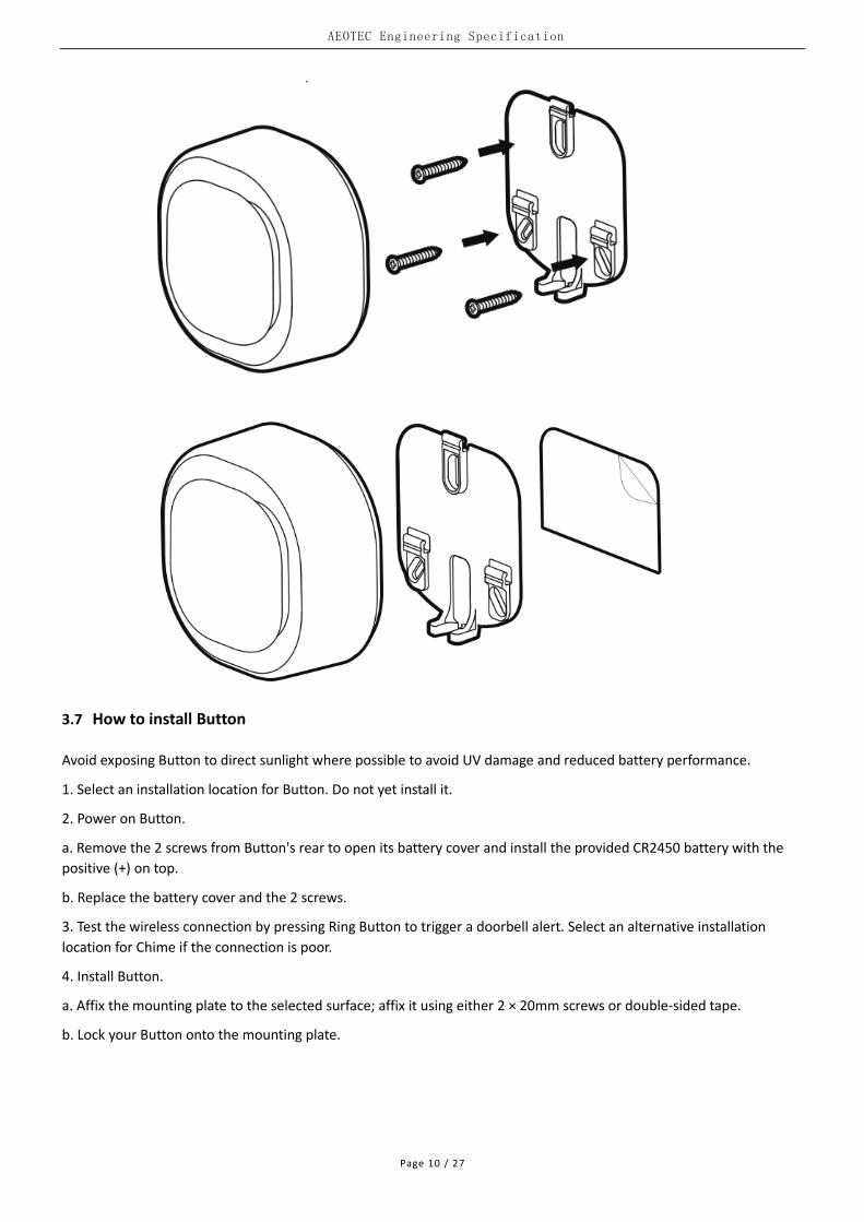
3.7 How to install Button
Avoid exposing Button to direct sunlight where possible to avoid UV damage and reduced battery performance.
1. Select an installation location for Button. Do not yet install it.
2. Power on Button.
a. Remove the 2 screws from Button's rear to open its battery cover and install the provided CR2450 battery with the
positive (+) on top.
b. Replace the battery cover and the 2 screws.
3. Test the wireless connection by pressing Ring Button to trigger a doorbell alert. Select an alternative installation
location for Chime if the connection is poor.
4. Install Button.
a. Affix the mounting plate to the selected surface; affix it using either 2 × 20mm screws or double-sided tape.
b. Lock your Button onto the mounting plate.

AEOTEC Engineering Specification
Page 11 / 27
3.8 How to pair Button
There are two way to trigger pairing Button:
Manually quick click Chime Action Button.
With Configuration Set. Please refer to Configuration Parameter=0x24 for details.
Below is mainly about manually quick click Chime Action Button to trigger pairing Button.
1. Different click times will trigger pairing different Button. Please action as shown below.
Click Action Button 3 times quickly will trigger pairing #1 Button.
Click Action Button 4 times quickly will trigger pairing #2 Button.
Click Action Button 5 times quickly will trigger pairing #3 Button.
2. Observe the Indicator Light of Chime to make sure which Button is waiting for pairing.
When pairing #1 Button is triggered, it will bright 1 time ON 0.5s OFF 1s, and then become constantly bright White
light, indicating that pairing #1 Button has already triggered. Pairing time is up to 10 seconds. In this time period,
user MUST manually click Ring Button 3 times quickly.
When pairing #2 Button is triggered, it will bright 2 times ON 0.5s OFF 1s, and then become constantly bright White
light, indicating that pairing #2 Button has already triggered. Pairing time is up to 10 seconds. In this time period,
user MUST manually click Ring Button 3 times quickly.
When pairing #3 Button is triggered, it will bright 3 times ON 0.5s OFF 1s, and then become constantly bright White
light, indicating that pairing #3 Button has already triggered. Pairing time is up to 10 seconds. In this time period,
user MUST manually click Ring Button 3 times quickly.
3. Determine pairing results.
If pairing Button succeeds, Chime will quickly flash White light 3 times and play the corresponding tone of paired
Button once, and then become breathing White light (when Chime is out of the Z-Wave network) or off (when Chime
is in the Z-Wave network)
If pairing Button fairs, Chime will slowly flash White light 3 times and then become breathing White light (when Chime
is out of the Z-Wave network) or off (when Chime is in the Z-Wave network).
Each successful pairing will overwrite the previous paired Button which has the same Button Number.

AEOTEC Engineering Specification
Page 12 / 27
Note:
ONLY one Button can be paired at a time.
This manually quick click Action Button operation can ONLY be used to trigger pairing, not unpairing.
3.9 How to unpair Button
There is ONLY one way to trigger unpairing Button:
With Configuration Set. Please refer to Configuration Parameter=0x24 for details.

AEOTEC Engineering Specification
Page 13 / 27
4 SOFTWARE FUNCTION DEFINITION
4.1 Function Overview
Function Item Description
Inclusion When the product is out of the network: If a controller is requesting to add a product and the product enters the Learning
Mode with sending Node Info, the product will be added to the controller's network with a NodeID assigned by the controller.
When the product is in the network: If a controller in the network is requesting to add a product and the product enters
the Learning Mode with sending Node Info, the product will be added to the controller's network again but the NodeID of the product will not change.
If a controller in another network is requesting to add a product and the product enters the Learning Mode with sending Node Info, the product will NOT be added to the controller's network.
Exclusion When the product is out of the network: If a controller is requesting to remove a product and the product enters the Learning
Mode with sending Node Info, the product will be removed from the controller's network, and keep being out of the network .
When the product is in the network: If a controller in the network is requesting to remove a product and the product
enters the Learning Mode with sending Node Info, the product will be removed from the controller's network, and become out of the network.
If a controller in another network is requesting to remove a product and the product enters the Learning Mode with sending Node Info, the product will be removed from the controller's network, and become out of the network.
Factory Reset Long press Action Button more than 20s. Please refer to Section 4.2 for details. Sending Configuration Set. Please refer to Configuration Parameter=0xFF for details.
Power-down Memory Remember the configuration information after the product is powered off.
Tone Play Play the built-in tone with Sound Switch Tone Play Set, Basic Set, or Configuration Set.
Volume Adjustment Adjust the volume with Sound Switch Configuration Set or Configuration Set.
Tone Group Include 1 Browse Group, 3 Remote Group, 2 Siren Group, and 1 Instant Group. Browse Group: Used for browsing the built-in tone, and can be triggered by Sound
Switch Tone Play Set, Basic Set, or Configuration Set. Remote Group: Used for Button wireless control, and can be triggered by Sound
Switch Tone Play Set, Basic Set, or Configuration Set, as well as paired Button. Siren Group: Cooperate with other nodes as a siren, and can be triggered by Sound
Switch Tone Play Set, Basic Set, or Configuration Set. Instant Group: Used for continuous playback without pause, and can be triggered by
Sound Switch Tone Play Set, Basic Set, or Configuration Set.
Tone Group Customization Can custom different Tone Group Parameters with Configuration Set, including Tone Index, Play Control, Play Mode, Volume, Light Effect Index, Interval Between 2 tones, Continuous Play Count, Intercept The Length Of A Tone. Tone Name can’t be customized by user.
Pair or Unpair Button A Chime supports up to 3 Buttons at the same time, while a Button can support multiple Chime at the same time.
There are two way to trigger pairing Button: Manually quick click Chime Action Button. Please refer to Section 3.8 for details. With Configuration Set. Please refer to Configuration Parameter=0x24 for details. There is ONLY one way to trigger unpairing Button: With Configuration Set. Please refer to Configuration Parameter=0x24 for details.
4.2 User Behavior Interaction
User behavior Out of the Z-Wave network In the Z-Wave network
Function Indicator Light Function Indicator Light
Power OFF NA OFF NA OFF

AEOTEC Engineering Specification
Page 14 / 27
Power ON Supply Power
When powered by battery, it will be breathing White light for 30 seconds (max). When powered by adapter, it will be breathing White light all the time.
Supply Power White light for 2 seconds and then become off.
Click Action Button once
Send Node Info for Inclusion
When click Action Button once, it will quickly flash White light for 30 seconds until Chime is added into the network. It will become constantly bright White light after being assigned a NodeID. If Inclusion succeeds, it will quickly flash White light 3 times and then off. If Inclusion fairs, it will slowly flash White light 3 times and then become breathing White light. If Action Button is clicked again during the network access process, the network access process will exit, at the same time the Indicator Light will extinguish immediately, and then become breathing White light.
Stop playing the sound and light
Immediately OFF
Click Action Button 3 times quickly
Trigger pairing #1 Button
It will bright 1 time ON 0.5s OFF 1s, and then become constantly bright White light, indicating that pairing #1 Button has already triggered. If pairing Button succeeds, it will quickly flash White light 3 times and then become breathing White light. If pairing Button fairs, it will slowly flash White light 3 times and then become breathing White light.
Trigger pairing #1 Button
It will bright 1 time ON 0.5s OFF 1s, and then become constantly bright White light, indicating that pairing #1 Button has already triggered. If pairing Button succeeds, it will quickly flash White light 3 times and then become off. If pairing Button fairs, it will slowly flash White light 3 times and then become off.
Click Action Button 4 times quickly
Trigger pairing #2 Button
It will bright 2 times ON 0.5s OFF 1s, and then become constantly bright White light, indicating that pairing #2 Button has already triggered. If pairing Button succeeds, it will quickly flash White light 3 times and then become breathing White light. If pairing Button fairs, it will slowly flash White light 3 times and then become breathing White light.
Trigger pairing #2 Button
It will bright 2 times ON 0.5s OFF 1s, and then become constantly bright White light, indicating that pairing #2 Button has already triggered. If pairing Button succeeds, it will quickly flash White light 3 times and then become off. If pairing Button fairs, it will slowly flash White light 3 times and then become off.
Click Action Button 5 times quickly
Trigger pairing #3 Button
It will bright 3 times ON 0.5s OFF 1s, and then become constantly bright White light, indicating that pairing #3 Button has already triggered. If pairing Button succeeds, it will quickly flash White light 3 times and then become breathing
Trigger pairing #3 Button
It will bright 3 times ON 0.5s OFF 1s, and then become constantly bright White light, indicating that pairing #3 Button has already triggered. If pairing Button succeeds, it will quickly flash White light 3 times and then become off. If

AEOTEC Engineering Specification
Page 15 / 27
White light. If pairing Button fairs, it will slowly flash White light 3 times and then become breathing White light.
pairing Button fairs, it will slowly flash White light 3 times and then become off.
Click Action Button 6 times quickly
Reserved Reserved Send Node Info for Exclusion
White light is on, up to 2s. If Exclusion succeeds, it will quickly flash White light 3 times and then become breathing White light. If Exclusion fairs, it will become off.
Long Press Action Button [1, 2s)
Reserved Keep off from press to release. Reserved Keep off from press to release.
Long Press Action Button [2, 5s)
Test the sound and light of the Browse Group
White light when press, and display in the default sound and light configuration of the Browse Group when release.
Test the sound and light of the Browse Group
White light when press, and display in the sound and light configuration of the Browse Group, based on Configuration Parameter 0x02, when release.
Long Press Action Button [5, 10s)
Reserved Brighter White light when press, and become off when release.
Reserved
Brighter White light when press, and quickly flash White
light when release,indicating
start to test communication quality between Chime and Node 1. At the end of the test, the White light is on for 2 seconds. If the communication quality is Good or Great, it will quickly flash White light 3 times and then become off. If the communication quality is Weak, it will slowly flash White light 3 times and then become off.
Long Press Action Button [10, 20s)
Reserved Speedup flashing White light when press, and become off when release.
Reserved Speedup flashing White light when press, and become off when release.
Long Press Action Button [20, ∞)
Factory Reset
When the time reaches 20s, the Factory Reset is performed no matter it is pressed or released. If Factory Reset succeeds, it will quickly flash White light 3 times and then become breathing White light.
Factory Reset after sending Device Reset Locally Notification Report
When the time reaches 20s, Factory Reset is performed no matter it is pressed or released. If Factory Reset succeeds, it will quickly f lash White light 3 times and then become breathing White light. If Factory Reset fails, it will become off when release.
4.3 Supplementary Explanation about Button
Function Description
Wireless Control Chime When click Ring Button once, Button can wireless control the corresponding paired Chime.
Pairing Chime When click Ring Button 3 times quickly, Button can be paired to Chime while Chime triggers pairing Button.
Sending Button Info to Chime When re-power or click Ring Button, Button will send its Button ID, Battery Voltage and Firmware Version to its corresponding paired Chime.
Automatic sleep After sending Button Info to Chime, Button will sleep automatically for saving batter y life.
Low Battery Indicator Light If #1 Button is low battery, Chime Indicator Light will repeat cycle (ON 100ms OFF 5s) If #2 Button is low battery, Chime Indicator Light will repeat cycle

AEOTEC Engineering Specification
Page 16 / 27
(ON 100ms OFF 100ms ON 100ms OFF 5s) If #3 Button is low battery, Chime Indicator Light will repeat cycle (ON 100ms OFF 100ms ON 100ms OFF 100ms ON 100ms OFF 5s) Low Battery Indicator Light will be activated when Chime detects the corresponding
paired Button is low battery, and disappears after the battery returns to normal. When the battery voltage of Button is lower than 2.8V, it is judged to be low battery. When the battery voltage of Button restores to over 2.9V, it is judged to return to
normal. Low Battery Indicator Light has the lowest priority among all l ight effects, that is, it
will be displayed when there is no other light effect. The light effect of the 3 Buttons are different. When multiple Buttons is low battery
at the same time, the corresponding light effect of the Button with smaller Button Number is displayed first.
4.4 Tone Group Priority Definition
(#1 Siren = #2 Siren) > (#1 Remote = #2 Remoter = #3 Remote) > (Browse = Instant)
Rule Description Example
A Tone Group is triggered, and the triggered Tone Group event is not released, if the other Tone Group event with lower priority than the Tone Group is triggered at this time, the Tone Group is maintained.
The #1 Siren Group is triggered and the Tone of #1 Siren Group is not stopped. At this time, if the paired #1 Button is clicked once, the Tone of the #1 Button Group will not be triggered, and the Tone of the #1 Siren Group will be maintained.
A Tone Group is triggered, and the triggered Tone Group event is not released, if the other Tone Group event with higher priority or the same priority than th e Tone Group is triggered, it is immediately replaced by the new Tone Group.
The #1 Remote Group is triggered and the Tone of #1 Remote Group is not stopped. At this time, if the paired #2 Button is clicked once, the Tone of the #1 Remote Group will be stopped, and the Tone of the #2 Remote Group will be play immediately.
4.5 SDK, Library and Device Classes
The application is based on:
Parameter Value
SDK 6.71.03
Library Enhanced 232 slave
Role Type Always On Slave (AOS)
Device Type Sound Switch
Supported security keys S0, S2_UNAUTHENTICATION, S2_AUTHENTICATION
4.6 Announced Command Classes in NIF
The application implements a number of mandatory and optional command classes.
Command Class Version Not added Non-secure added Securely added
Non-secure CC Secure CC
ZWAVEPLUS_INFO 2 Support Support Support
VERSION 2 Support Support Support
CONFIGURATION 1 Support Support Support
MANUFACTURER_SPECIFIC 2 Support Support Support
ASSOCIATION_GRP_INFO 1 Support Support Support
ASSOCIATION 2 Support Support Support
POWERLEVEL 1 Support Support Support
MULTI_CHANNEL_ASSOCIATION 3 Support Support Support
MULTI_CHANNEL 4 Support Support Support

AEOTEC Engineering Specification
Page 17 / 27
DEVICE_RESET_LOCALLY 1 Support Support Support
TRANSPORT_SERVICE 2 Support Support Support
SECURITY 1 Support Support Support
SECURITY_2 1 Support Support Support
SUPERVISION 1 Support Support Support
FIRMWARE_UPDATE_MD 4 Support Support Support
NOTIFICATION 8 Support Support Support
SOUND_SWITCH 1 Support Support Support
4.7 Basic Command Class mapping
Basic Set Command (value) maps to Sound Switch Tone Play Set Command (Tone Identifier).
Basic Get Command maps to Sound Switch Tone Play Get Command.
Basic Report Command maps to Sound Switch Tone Play Report Command.
4.8 Z-Wave Plus Info
Parameter Value
Z-Wave Plus Version 1
Role Type 5 (ZWAVEPLUS_INFO_REPORT_ROLE_TYPE_SLAVE_ALWAYS_ON)
Node Type 0 (ZWAVEPLUS_INFO_REPORT_NODE_TYPE_ZWAVEPLUS_NODE )
Installer Icon Type 0x2000 (ICON_TYPE_GENERIC_SOUND_SWITCH)
User Icon Type 0x2000 (ICON_TYPE_GENERIC_SOUND_SWITCH)
4.9 Manufacturer Specific
Parameter Value
Manufacturer ID 1 0x03
Manufacturer ID 2 0x71
Product Type ID 1 EU=0x00, US=0x01, AU=0x02, CN=0x1D
Product Type ID 2 0x03
Product ID 1 0x00
Product ID 2 0xA2
4.10 Version
Parameter Value
Z-Wave Protocol Library Type 0x03
Z-Wave Protocol Version 0x05
Z-Wave Protocol Sub Version 0x03
Firmware 0 Version ZM5101 Software Version MSB
Firmware 0 Sub Version ZM5101 Software Version LSB
Hardware Version 0xA2
Number of firmware targets 0x00
4.11 Multi Channel
Parameter Value
Individual End Points 7
Aggregated End Points 0

AEOTEC Engineering Specification
Page 18 / 27
Dynamic 0
Identical 1
Generic Device Class GENERIC_TYPE_AV_CONTROL_POINT
Specific Device Class SPECIFIC_TYPE_SOUND_SWITCH
Command Classes COMMAND_CLASS_ZWAVEPLUS_INFO COMMAND_CLASS_SECURITY COMMAND_CLASS_SECURITY_2 COMMAND_CLASS_SUPERVISION COMMAND_CLASS_ASSOCIATION COMMAND_CLASS_ASSOCIATION_GRP_INFO COMMAND_CLASS_MULTI_CHANNEL_ASSOCIATION COMMAND_CLASS_NOTIFICATION COMMAND_CLASS_SOUND_SWITCH
4.12 Sound Switch
(1)Sound Switch Tones Number Report Command
Supported Tones = 10 (example)
(2)Sound Switch Tone Info Report Command (example)
Tone Identifier Tone Duration Name Length Name
1 0x0014 8 1AMBUL~1
2 0x0001 8 2ALARM~1
3 0x0014 8 3POLIC~1
4 0x003A 8 4FIRE~1
5 0x000F 8 5GASLE~1
6 0x0003 8 6MODER~1
7 0x000B 8 7ELECT~1
8 0x0002 8 8CLASS~1
9 0x003C 8 9ARMIN~1
10 0x003C 8 10SECU~1
(3)Sound Switch Configuration Report Command
Parameter Valid Value Default Value
Volume 0..7 7
Default Tone Identifier 0..Supported Tones 1
Note:
Since the tones in the Chime may be changed according to customer requirements, the Supported Tones and the Tone
Info may be different. However, the difference will not affect the normal use of the application.
Besides, the Default Value of Volume and Default Tone Identifier in Sound Switch Configuration Report Command will
not be modified the initial defaults although the customer requests to change tones.
4.13 Notification
Notification Type Notification Events Description
Home Security 0x07 State idle 0x00 Vibration event is inactive
Tampering, product cover removed 0x03 Vibration event is triggered
Power Management 0x08 State idle 0x00 Button’s battery comes back to normal
Replace battery soon 0x0A Button’s battery is in low battery
Siren 0x0E State idle 0x00 Chime alarm is inactive
Siren active 0x01 Chime alarm is triggered
AEOTEC Engineering Specification
Page 19 / 27
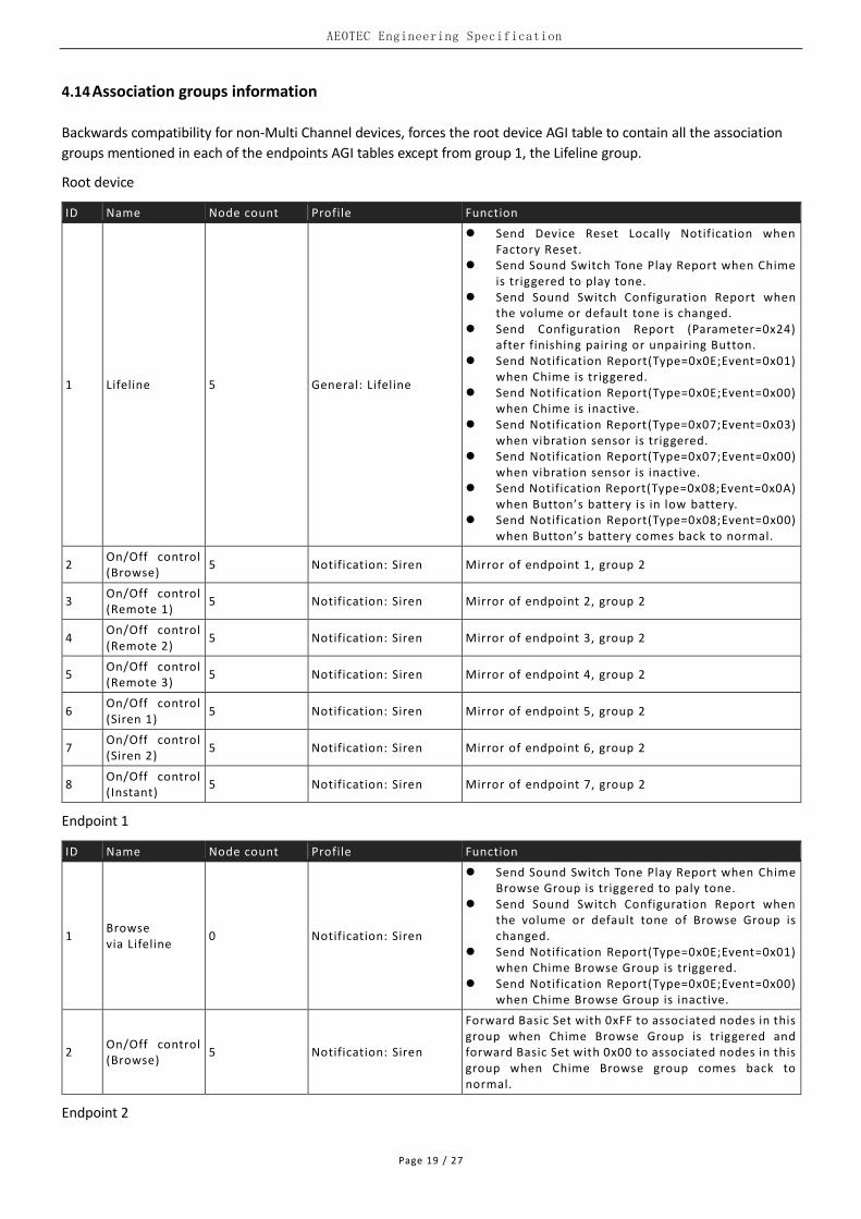
4.14 Association groups information
Backwards compatibility for non-Multi Channel devices, forces the root device AGI table to contain all the association
groups mentioned in each of the endpoints AGI tables except from group 1, the Lifeline group.
Root device
ID Name Node count Profile Function
1 Lifeline 5 General: Lifeline
Send Device Reset Locally Notification when Factory Reset.
Send Sound Switch Tone Play Report when Chime is triggered to play tone.
Send Sound Switch Configuration Report when the volume or default tone is changed.
Send Configuration Report (Parameter=0x24) after finishing pairing or unpairing Button.
Send Notification Report(Type=0x0E;Event=0x01) when Chime is triggered.
Send Notification Report(Type=0x0E;Event=0x00) when Chime is inactive.
Send Notification Report(Type=0x07;Event=0x03) when vibration sensor is triggered.
Send Notification Report(Type=0x07;Event=0x00) when vibration sensor is inactive.
Send Notification Report(Type=0x08;Event=0x0A) when Button’s battery is in low battery.
Send Notification Report(Type=0x08;Event=0x00) when Button’s battery comes back to normal.
2 On/Off control (Browse)
5 Notification: Siren Mirror of endpoint 1, group 2
3 On/Off control (Remote 1)
5 Notification: Siren Mirror of endpoint 2, group 2
4 On/Off control (Remote 2)
5 Notification: Siren Mirror of endpoint 3, group 2
5 On/Off control (Remote 3)
5 Notification: Siren Mirror of endpoint 4, group 2
6 On/Off control (Siren 1)
5 Notification: Siren Mirror of endpoint 5, group 2
7 On/Off control (Siren 2)
5 Notification: Siren Mirror of endpoint 6, group 2
8 On/Off control (Instant)
5 Notification: Siren Mirror of endpoint 7, group 2
Endpoint 1
ID Name Node count Profile Function
1 Browse via Lifeline
0 Notification: Siren
Send Sound Switch Tone Play Report when Chime Browse Group is triggered to paly tone.
Send Sound Switch Configuration Report when the volume or default tone of Browse Group is changed.
Send Notification Report(Type=0x0E;Event=0x01) when Chime Browse Group is triggered.
Send Notification Report(Type=0x0E;Event=0x00) when Chime Browse Group is inactive.
2 On/Off control (Browse)
5 Notification: Siren
Forward Basic Set with 0xFF to associated nodes in this group when Chime Browse Group is triggered and forward Basic Set with 0x00 to associated nodes in this group when Chime Browse group comes back to normal.
Endpoint 2

AEOTEC Engineering Specification
Page 20 / 27
ID Name Node count Profile Function
1 Remote 1 via Lifeline
0 Notification: Siren
Send Sound Switch Tone Play Report when Chime #1 Remote Group is triggered to paly tone.
Send Sound Switch Configuration Report when the volume or default tone of #1 Remote Group is changed.
Send Notification Report(Type=0x0E;Event=0x01) when Chime #1 Remote Group is triggered.
Send Notification Report(Type=0x0E;Event=0x00) when Chime #1 Remote Group is inactive.
Send Notification (Type=0x08; Event=0x0A) when Chime #1 Button’s battery is in low battery.
Send Notification (Type=0x08; Event=0x00) when Chime #1 Button’s battery comes back to normal.
2 On/Off control (Remote 1)
5 Notification: Siren
Forward Basic Set with 0xFF to associated nodes in this group when Chime #1 Remote Group is triggered and forward Basic Set with 0x00 to associated nodes in this group when Chime #1 Remote Group comes back to normal.
Endpoint 3
ID Name Node count Profile Function
1 Remote 2 via Lifeline
0 Notification: Siren
Send Sound Switch Tone Play Report when Chime #2 Remote Group is triggered to paly tone.
Send Sound Switch Configuration Report when the volume or default tone of #2 Remote Group is changed.
Send Notification Report(Type=0x0E;Event=0x01) when Chime #2 Remote Group is triggered.
Send Notification Report(Type=0x0E;Event=0x00) when Chime #2 Remote Group is inactive.
Send Notification (Type=0x08; Event=0x0A) when Chime #2 Button’s battery is in low battery.
Send Notification (Type=0x08; Event=0x00) when Chime #2 Button’s battery comes back to normal.
2 On/Off control (Remote 2)
5 Notification: Siren
Forward Basic Set with 0xFF to associated nodes in this group when Chime #2 Remote Group is triggered and forward Basic Set with 0x00 to associated nodes in this group when Chime #2 Remote Group comes back to normal.
Endpoint 4
ID Name Node count Profile Function
1 Remote 3 via Lifeline
0 Notification: Siren
Send Sound Switch Tone Play Report when Chime #3 Remote Group is triggered to paly tone.
Send Sound Switch Configuration Report when the volume or default tone of #3 Remote Group is changed.
Send Notification Report(Type=0x0E;Event=0x01) when Chime #3 Remote Group is triggered.
Send Notification Report(Type=0x0E;Event=0x00) when Chime #3 Remote Group is inactive.
Send Notification (Type=0x08; Event=0x0A) when Chime #3 Button’s battery is in low battery.
Send Notification (Type=0x08; Event=0x00) when Chime #3 Button’s battery comes back to normal.
2 On/Off control (Remote 3)
5 Notification: Siren
Forward Basic Set with 0xFF to associated nodes in this group when Chime #3 Remote Group is triggered and forward Basic Set with 0x00 to associated nodes in this group when Chime #3 Remote Group comes back to normal.
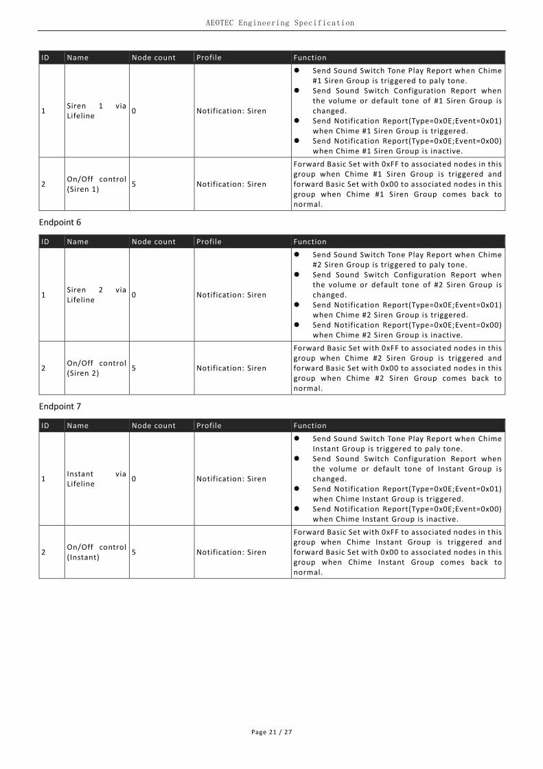
Endpoint 5
AEOTEC Engineering Specification
Page 21 / 27
ID Name Node count Profile Function
1 Siren 1 via Lifeline
0 Notification: Siren
Send Sound Switch Tone Play Report when Chime #1 Siren Group is triggered to paly tone.
Send Sound Switch Configuration Report when the volume or default tone of #1 Siren Group is changed.
Send Notification Report(Type=0x0E;Event=0x01) when Chime #1 Siren Group is triggered.
Send Notification Report(Type=0x0E;Event=0x00) when Chime #1 Siren Group is inactive.
2 On/Off control (Siren 1)
5 Notification: Siren
Forward Basic Set with 0xFF to associated nodes in this group when Chime #1 Siren Group is triggered and forward Basic Set with 0x00 to associated nodes in this group when Chime #1 Siren Group comes back to normal.
Endpoint 6
ID Name Node count Profile Function
1 Siren 2 via Lifeline
0 Notification: Siren
Send Sound Switch Tone Play Report when Chime #2 Siren Group is triggered to paly tone.
Send Sound Switch Configuration Report when the volume or default tone of #2 Siren Group is changed.
Send Notification Report(Type=0x0E;Event=0x01) when Chime #2 Siren Group is triggered.
Send Notification Report(Type=0x0E;Event=0x00) when Chime #2 Siren Group is inactive.
2 On/Off control (Siren 2)
5 Notification: Siren
Forward Basic Set with 0xFF to associated nodes in this group when Chime #2 Siren Group is triggered and forward Basic Set with 0x00 to associated nodes in this group when Chime #2 Siren Group comes back to normal.
Endpoint 7
ID Name Node count Profile Function
1 Instant via Lifeline
0 Notification: Siren
Send Sound Switch Tone Play Report when Chime Instant Group is triggered to paly tone.
Send Sound Switch Configuration Report when the volume or default tone of Instant Group is changed.
Send Notification Report(Type=0x0E;Event=0x01) when Chime Instant Group is triggered.
Send Notification Report(Type=0x0E;Event=0x00) when Chime Instant Group is inactive.
2 On/Off control (Instant)
5 Notification: Siren
Forward Basic Set with 0xFF to associated nodes in t his group when Chime Instant Group is triggered and forward Basic Set with 0x00 to associated nodes in this group when Chime Instant Group comes back to normal.

AEOTEC Engineering Specification
Page 22 / 27
4.15 Configuration
Param. Description W/R Default Size
0x02 (2)
Set or Get Browse Group
7 6 5 4 3 2 1 0
Tone Index Play Control
Reserved Volume
Reserved Light Effect Index
Play Mode
Tone Index (Max=Supported Tones)
Value Description
0 Reserved
1..Max Set the default tone
Other Reserved
31 Use last valid configuration
Play Control
Value Description
0 Set but not play
1 Play
2 Stop
3 Previous (In this case, Tone Index MUST be equal to 31)
4 Next (In this case, Tone Index MUST be equal to 31)
5 Reserved
6 Reserved
7 Use last valid configuration
Volume
Value Description
0 Mute
1..7 1 is the minimum volume, while 7 is the maximum volume
8..14 Reserved
15 Use last valid configuration
Light Effect Index
Value Description
0..6 Select the specified Light Effect. The Light Effect can be configured by parameter 0x0A-0x10
7 Use last valid configuration
Play Mode
Value Description
0 Single No Loop Play
1 Single Loop Play
2 List Loop Play
3 List Random Play
4..254 Reserved
255 Use last valid configuration
Note: Tone Index maps to the Default Tone Identifier of Sound Switch Configuration Set CC. Volume maps to the Volume of Sound Switch Configuration Set CC.
WR 0x34070000 4
0x03 (3)
Set or Get #1 Remote Group
7 6 5 4 3 2 1 0
Tone Index Play Control
Interval Between 2 Tones Volume
Continuous Play Count Light Effect Index
Intercept The Length Of A Tone
WR 0x09070914 4

AEOTEC Engineering Specification
Page 23 / 27
Tone Index (Max=Supported Tones)
Value Description
0 Reserved
1..Max Set the default tone
Other Reserved
31 Use last valid configuration
Control
Value Description
0 Set but not play
1 Play
2 Stop
3..6 Reserved
7 Use last valid configuration
Volume
Value Description
0 Mute
1..7 1 is the minimum volume, while 7 is the maximum volume
8..14 Reserved
15 Use last valid configuration
Interval Between 2 Tones
Value Description
0 Not stopping
1..14 1-14 seconds, the interval time between 2 tones
15 Use last valid configuration
Light Effect Index
Value Description
0..6 Select the specified Light Effect. The Light Effect can be configured by parameter 0x0A-0x10
7 Use last valid configuration
Continuous Play Count
Value Description
0 Continuous Play
1..30 1-30 times, the count that the tone will be repeated to be played
31 Use last valid configuration
Intercept The Length Of A Tone
Value Description
0 The Length Of A Tone Itself.
1..254 1-254 seconds, Intercept The Length Of A Tone. Actual Single Play Time is equal to the smaller value between The Length Of A Tone Itself and Intercept The Length Of A Tone.
255 Use last valid configuration
Note: Tone Index maps to the Default Tone Identifier of Sound Switch Configuration Set CC. Volume maps to the Volume of Sound Switch Configuration Set CC.
Total Tone Playback Time = Continuous Play Count x ( Actual Single Play Time + Interval Between 2 Tones )
0x04 (4)
Set or Get #2 Remote Group
7 6 5 4 3 2 1 0
Tone Index Play Control
Interval Between 2 Tones Volume
Continuous Play Count Light Effect Index
Intercept The Length Of A Tone
Note: The valid values can be referenced to the definition of parameter 0x03.
WR 0x19070914 4

AEOTEC Engineering Specification
Page 24 / 27
0x05 (5)
Set or Get #3 Remote Group
7 6 5 4 3 2 1 0
Tone Index Play Control
Interval Between 2 Tones Volume
Continuous Play Count Light Effect Index
Intercept The Length Of A Tone
Note: The valid values can be referenced to the definition of parameter 0x03.
WR 0x29070914 4
0x06 (6)
Set or Get #1 Siren Group
7 6 5 4 3 2 1 0
Tone Index Play Control
Interval Between 2 Tones Volume
Continuous Play Count Light Effect Index
Intercept The Length Of A Tone
Note: The valid values can be referenced to the definition of parameter 0x03.
WR 0x89070A14 4
0x07 (7)
Set or Get #2 Siren Group
7 6 5 4 3 2 1 0
Tone Index Play Control
Interval Between 2 Tones Volume
Continuous Play Count Light Effect Index
Intercept The Length Of A Tone
Note: The valid values can be referenced to the definition of parameter 0x03.
WR 0x91070A14 4
0x08 (8)
Set or Get Instant Group
7 6 5 4 3 2 1 0
Tone Index Play Control
Interval Between 2 Tones Volume
Continuous Play Count Light Effect Index
Intercept The Length Of A Tone
Note: The valid values can be referenced to the definition of parameter 0x03. The valid values of Interval Between 2 Tones are only 0 and 15. The valid values of Continuous Play Count are only 0 and 31.
WR 0x79070314 4
0x0A (10)
Set or Get Light Effect Index 0
7 6 5 4 3 2 1 0
Brighten Duration
Dim Duration
Light ON Duration
Light OFF Duration
Brighten Duration The time from Light OFF to Light ON. (Unit = 10ms)
Dim Duration The time from Light ON to Light OFF. (Unit = 10ms)
Light On Duration The time of Light ON. (Unit = 100ms)
Light Off Duration The time of Light OFF. (Unit = 100ms)
Note: Total Light Effect Time = Brighten + Dim + Light ON + Light OFF
WR 0x96321403 4
0x0B (11)
Set or Get Light Effect Index 1 Note: The valid values can be referenced to the definition of parameter 0x0A.
WR 0x64640003 4
0x0C Set or Get Light Effect Index 2 WR 0x00420103 4

AEOTEC Engineering Specification
Page 25 / 27
(12) Note: The valid values can be referenced to the definition of parameter 0x0A .
0x0D (13)
Set or Get Light Effect Index 3 Note: The valid values can be referenced to the definition of parameter 0x0A .
WR 0x42000003 4
0x0E (14)
Set or Get Light Effect Index 4 Note: The valid values can be referenced to the definition of parameter 0x0A .
WR 0x0000000A 4
0x0F (15)
Set or Get Light Effect Index 5 Note: The valid values can be referenced to the definition of parameter 0x0A .
WR 0x00000A00 4
0x10 (16)
Set or Get Light Effect Index 6 Note: The valid values can be referenced to the definition of parameter 0x0A .
WR 0x42000001 4
0x11 (17)
Set or Get the volume of vibration sensor alarm
Value Description
0 Mute
1-7 1 is the minimum volume, while 7 is the maximum volume
Other Reserved
WR 7 1
0x20 (32)
Communication Quality Report (REPORT ONLY)
Value Description
0 Weak
15 Good
255 Great
Other Reserved
Note: Can be used to confirm the communication quality betwee n Chime and Node 1. The function will be activated after long pressing Action Button for 5 seconds.
NA - 1
0x21 (33)
Get the information of #1 Button (GET ONLY)
7 6 5 4 3 2 1 0
Button Pairing State
Button Battery Voltage MSB
Button Battery Voltage LSB
Button Firmware Version
Button Pairing State
Value Description
0 Unpaired
1 Paired
Other Reserved
Button Battery Voltage MSB & LSB
Value Description
0 Unpaired
1-66634 The unit of Battery Voltage is mV
65535 Low power
Button Firmware Version
Bit Description
Bit 0~3 The LSB of Button Firmware Version
Bit 4~7 The MSB of Button Firmware Version
For example, if Button Firmware Version equals to 0x10, it means V1.00. Note: This parameter does not restore the default value when remove from the network or reset the factory settings.
R - 4
0x22 (34)
Get the information of #2 Button Note: The valid values can be referenced to the definition of parameter 0x21 .
R - 4
0x23 (35)
Get the information of #3 Button Note: The valid values can be referenced to the definition of parameter 0x21 .
R - 4

AEOTEC Engineering Specification
Page 26 / 27
0x24 (36)
Pair or Unpair Button
7 6 5 4 3 2 1 0
Pairing Control Button Number Bit Mask
Set: Button Number Bit Mask(4 bits)
Bit Description
Bit 0 #1 Button
Bit 1 #2 Button
Bit 2 #3 Button
Bit 3 Reserved
If want to pair or unpair the specified Button, the sending node MUST set the corresponding bit of Button to 1. Pairing Control (4 bits)
Value Description
0 Unpair Button
1 Pair Button
Other Reserved
Pair Button ONLY one Button can be paired at a time. The node will ignore commands which want to pair multiple Buttons at the same time. When pairing Button is triggered, Chime will always bright White light. Pairing time is up to 10 seconds. In this time period, user MUST manually click Ring Button 3 times quickly. If pairing Button succeeds, Chime will quickly flash White light 3 times and play the corresponding tone of paired Button once, and then become off. Each successful pairing will overwrite the previous paired Button which has the same Button Number. If pairing Button fails, Chime will slowly flash White light 3 times and then become off. Unpair Button Multiple Buttons can be unpaired at a time. When unpairing Button is triggered, user does NOT need to do anything to the Button. When unpairing Button is finished, Chime will quickly flash White light 3 times and then become off. Get: Can be used to request which Buttons has been paired after finishing pairing or unpairing Button. Report: When pairing Button is triggered, Chime will automatically report 0x24 once to notify which Button is waiting for pairing. At this moment, the Pairing Control is equal to 1 , and the corresponding bit of Button is equal to 1. When pairing Button is finished, Chime will automatically report 0x24 once to notify which Buttons has been paired. At this moment, the Pairing Control is equal to 2, and the corresponding bit of Button which has been paired is equal to 1 while the corresponding bit of Button which has been unpaired is equal to 0.
When unpairing Button is finished, Chime will automatically report 0x24 once to notify which Buttons has been unpaired. At this moment, the Pairing Control is equal to 2, and the corresponding bit of Button which has been paired is equal to 1 while the corresponding bit of Button which has been unpaired is equal to 0.
WR - 1
AEOTEC Engineering Specification
Page 27 / 27
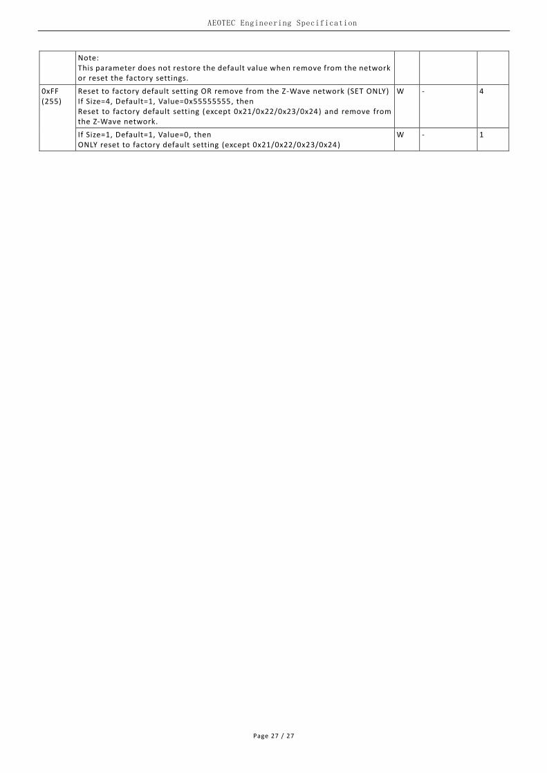
Note: This parameter does not restore the default value when remove from the network or reset the factory settings.
0xFF (255)
Reset to factory default setting OR remove from the Z-Wave network (SET ONLY) If Size=4, Default=1, Value=0x55555555, then Reset to factory default setting (except 0x21/0x22/0x23/0x24) and remove from the Z-Wave network.
W - 4
If Size=1, Default=1, Value=0, then ONLY reset to factory default setting (except 0x21/0x22/0x23/0x24)
W - 1