
Engineering Mechanics Prof. Dr. G. Saravana Kumar ...textofvideo.nptel.ac.in/112103108/lec3.pdf ·...
24
Engineering Mechanics Prof. Dr. G. Saravana Kumar Department of Mechanical Engineering Indian Institute of Technology, Guwahati Module No. # 02 Engineering Mechanics Lecture No. # 03 Truss Analysis Part-1 (Refer Slide Time: 01:14) One such civil structure, which is known as trusses and we will see how do we analyze them, and determine the forces acting on its various members, in order to predict the performance of such structures. The picture accompanying the slide shows a typical truss used to support bridges; other examples are the roof supports, the derricks, the structures used to support the radio antennas and high voltage cables. All these trusses have one common characteristic, that they constitute of only straight members and they are connected at their extremities. As see you in this example, you have many straight elements, which are connected at their extremities only.
Transcript of Engineering Mechanics Prof. Dr. G. Saravana Kumar ...textofvideo.nptel.ac.in/112103108/lec3.pdf ·...

Engineering Mechanics
Prof. Dr. G. Saravana Kumar
Department of Mechanical Engineering
Indian Institute of Technology, Guwahati
Module No. # 02
Engineering Mechanics
Lecture No. # 03
Truss Analysis Part-1
(Refer Slide Time: 01:14)
One such civil structure, which is known as trusses and we will see how do we analyze
them, and determine the forces acting on its various members, in order to predict the
performance of such structures. The picture accompanying the slide shows a typical truss
used to support bridges; other examples are the roof supports, the derricks, the structures
used to support the radio antennas and high voltage cables.
All these trusses have one common characteristic, that they constitute of only straight
members and they are connected at their extremities. As see you in this example, you
have many straight elements, which are connected at their extremities only.

(Refer Slide Time: 02:24)
Let us see this example little more clearly. This picture shows a part of the bridge; so this
is the bridge platform, which is supported by beams and these beams are supported by
the trusses. So, here you see one plane truss in the front and another plane truss at the
rear; plane trusses are trusses, whose elements lies in a single plane and their loading is
also in the same plane. So, the problem can be analyzed as a two-dimensional problem.
So, let us take one of these trusses; let us say the front set of elements and that is shown
in this picture; here we see that the loads are carried by these beams and they are
transmitted to the truss through these joints. So, that is what you see in this picture as the
various loads P 1, P 2, P 3. So, one thing that we observe is that, all these external loads
that are applied on the truss, is applied to its joints only and we have seen that the truss
constitute of many linear elements, straight elements and connected at their extremities.
For a better analysis, we may have to also include the weight of the truss for better
prediction of the internal forces. These are the supports; we have one support at A and
another support at B. Typically, a truss is supported by a pin joint and a roller joint, a
plane truss is supported by a pin joint and a roller support. This comes from our
understanding of the basic equilibrium of two-dimensional objects; from the equilibrium
equations we can determine three unknowns. So, it is possible to determine the two
reaction components, that is, let us say A y and A x as well as one vertical component,
that is B y at the joint B.

(Refer Slide Time: 05:20)
Some other things that you may have to remember is that, these members being slender,
they cannot support lateral loads; that means, we cannot apply a load at this point and the
loads have to be only applied at extremities - that is the joints.
And we see that the truss is predominantly a structure, which constitutes of such slender
members, which are two-force members and the pins. This member is a two-force
member, because each member has two joints, and if a member has to be in equilibrium,
those two forces have to be collinear, and it has to be along the access of the element.
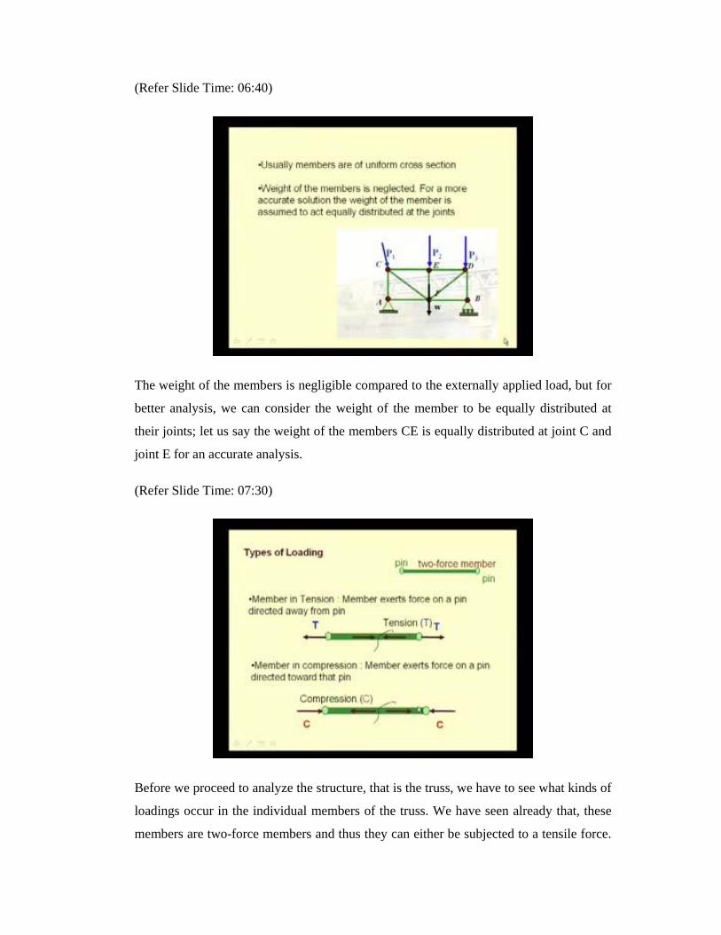
Usually the members are designed with uniform cross-section, because it is possible to
manufacture a bar stock of a uniform cross section and cut them to the required length to
construct the entire truss.
(Refer Slide Time: 06:40)
The weight of the members is negligible compared to the externally applied load, but for
better analysis, we can consider the weight of the member to be equally distributed at
their joints; let us say the weight of the members CE is equally distributed at joint C and
joint E for an accurate analysis.
(Refer Slide Time: 07:30)
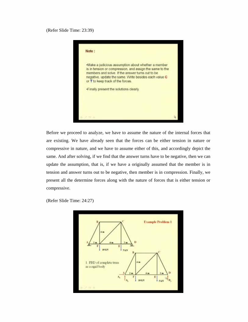
Before we proceed to analyze the structure, that is the truss, we have to see what kinds of
loadings occur in the individual members of the truss. We have seen already that, these
members are two-force members and thus they can either be subjected to a tensile force.

This picture shows the tension loading; you have the two pins connected at the
extremities of this two-force member and the externally applied load or the loads from
the other connected members, pull this member at the two joints. So, in order to resist the
deformation, the member develops an internal force, which tries to keep the various parts
of the member in equilibrium, and thereby these forces pull the member towards itself;
that is at the joint, the internal force is acting away from the joint.
The other kind of loading that is possible is the compressive load, where the external
load or the loads from other members push the joint; thereby, the internal force
developed in the member is towards the joint. So, when we consider only part of the
member in a free body diagram, one has to keep these directions in mind, in order to
construct the proper force directions in a free body diagram.
(Refer Slide Time: 09:22)
Before we proceed to analyze the structure, one has to understand what we mean by a
rigid truss. So, here we see the most simplest form of a truss, that is, three elements AB,
B C and AC connected at A, B and C and the truss is supported by a pin joint at A and a
roller joint at C.
If we consider any two-dimensional element, and which is not constrain, it has 3 degrees
of freedom in this plane; that is, it can translate in the x direction and in the y direction,
and it can rotate about the z-axis. So, each of the two-dimensional elements has 3
degrees of freedom. So, if we connect and another member, let us say the first member is

AC and we connect it with another member C B, then 2 of its degrees are arrested. So, if
we have three sets elements connected at their extremities, out of the 9 degrees of
freedom, that is, 3 degrees of freedom individually for each member, for each of these
joints 2 degrees are arrested; so 6 degrees of freedom are arrested, the remaining degrees
of freedom that this combined structure has is 3.
So, these 3 degrees of freedom have to be arrested by external supports and that is what
we see that at A, we put a pin connection; so, thereby, it offers both reaction component
A y and A x to arrest any translation and the rotation degree of freedom is arrested by
providing a roller at C. So, we see that, this combination, that is three elements AB, BC
and AC connected at three joints is clearly a rigid element, which does not undergoes
any deformation when some external forces are applied.
(Refer Slide Time: 12:40)
So, here we see an example of a truss which is not rigid. Here we see these members AB,
BD, CD and AC, connected at A, B, D and C and supported by a pin joint at A and roller
joint at C, but under the action of this external force at B, this truss element deforms,
because sufficient number of degrees of freedoms have not been restrainted.
So, when we design trusses, we have to design the truss to be rigid under the action of
external forces. Here we see an example of an over rigid truss. In an over rigid truss, the
rigidity of the structure is not effected even if we remove, let us say one of the elements,

let us say if we remove this element BD, then also we see that the structure does not
deforms under the action of any load, let us say at D or at B.
In order to optimally design a truss, we have to design trusses which are just rigid, that
means, sufficient number of degrees of freedoms have been arrested and we do not have
additional members, which you know, if we see in terms of economics, is not viable. So,
here we see an truss which is just rigid; here even if you remove one of the members
either BD, CD, the rigidity of the truss is lost and the structure deforms under the action
of any external loads. And we are interested to design such kinds of trusses, which are
just rigid.
(Refer Slide Time: 14:54)
Let us see what we mean by simple trusses. The triangular truss that we have just seen,
that is, we have this element AB, BC and AC connected by a roller at a and by a pin joint
at A and a roller at C; this element is a, this truss element is a rigid truss and it is known
as a simple truss. If we add two more members and a joint, then this structure is also
rigid; that is, we replicate this combination of the element and joints, which form a
triangular pattern, and if this is replicated in this plane, we get simple plane trusses.
These trusses have one property, that the number of members if we designate it as m is
equal to 2 times the number of joints; if we have designated it has n, then 2 n minus 3.
So, let us see for this example, we have 3 plus 2, that is 5 members and 4 joints; so 2 n
minus 4 is 8 minus 3 which is 5; so, this equation is valid; and such kind of trusses are

statically determinate; why do we say that they are statically determinate? Internally is
that, if we analyze this structure and we want to determine all the internal forces, then the
number of unknown that we have to determine is equal to the number of members, that
is, 5 in this case plus the external reactions that we have to determine that is 3; two
reactions at the pin and one reaction at the roller totaling to eight unknowns.
If we consider the free body diagram of a single joint, let us say joint D, then for the joint
D to be in equilibrium, the sum of all the forces has to be 0; the moments are obviously
0, because all the forces are concurrent at D. So, these forces does not cause moments
and so the summation of moment is obviously 0, but for the joint D to be in equilibrium,
the summation of forces have to be also be 0. And in 2 D, this results in two equations,
that is, summation of the horizontal component of the forces and summation of vertical
component of the forces.
So, for each joint from the free body diagram, one can determine two unknowns. So, if
we have n numbers of joints in a truss, then we can determine 2n number of unknowns.
So, for the problem to be statically determinate, the number unknowns, that is, m plus 3
should be equal to the number of equations that we can write; that is 2n and that is what
this equation depicts that n is equal to 2 n minus 3. If we extend these discussion to 3 D,
then a simple three-dimensional truss is a tetrahedral constituting of six elements
connected at four joints that is A, B, C and D.
Initially, we will see analysis of simple plane trusses. The internal forces of the trusses
can be determined by two methods: one is known the method of joints and the other the
method of sections. Initially, let us see how to determine the forces in various members
by method of joints. As the name suggests, the method primarily relies on determining
the internal forces from the equilibrium equations of constituent joints.

(Refer Slide Time: 20:10)
So, let us see the procedure. Initially, we determine the external reaction at the supports
by considering the free body diagram of the complete truss. Obviously, we assume that
the structure is externally statically determinate; that means, it is possible to find all the
external reactions. Next, we consider the free body diagram of each of the joints or pins,
and we show the external forces, as well as the forces exerted by the support, and the
forces exerted by various member connected at the joints in the free body diagram.
Here, we will see that for a plane truss, if we have m number of members, then we have
m number of unknowns plus three number of external reactions to be determined and the
number of equations from the n joints will be, 2 n; and thus for the problem to be
statically determinate, m plus 3 should be equal to 2 n. In 3 D, we see that, the force
summation equation at each joint result in three scalar equations; thereby, we can
determine three unknowns for each of the free body diagram from the joint. So, the
number of unknowns, that is, the number of members in the truss plus the number of
unknown reactions, that is 6 in case of three-dimensional trusses, should be equal to 3n
for a space truss.

(Refer Slide Time: 22:20)
Obviously, here we should remember that these equations are not independent of the
external equations used for determining the external reactions. Few more points to be
noted are, if the geometry of the truss is known, then the direction of all the internal
forces, that is, the forces that exist in each of the members is also known; only the
magnitude of the those forces is unknown. And in case of simple trusses, it is possible to
draw the free-body diagrams of the joints such that, at any instant we only have two
unknowns; so thereby, we do not need to solve simultaneous equation, rather we can
solve at a time only two unknowns from each of the equations, from each of the free
body diagram. The forces can be obtained from this equations and one can also perform
checks as we proceed.
(Refer Slide Time: 23:39)
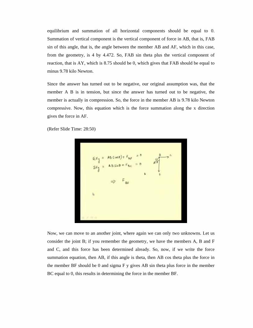
Before we proceed to analyze, we have to assume the nature of the internal forces that
are existing. We have already seen that the forces can be either tension in nature or
compressive in nature, and we have to assume either of this, and accordingly depict the
same. And after solving, if we find that the answer turns have to be negative, then we can
update the assumption, that is, if we have a originally assumed that the member is in
tension and answer turns out to be negative, then member is in compression. Finally, we
present all the determine forces along with the nature of forces that is either tension or
compressive.
(Refer Slide Time: 24:27)

Let us see the complete procedure with an example. Here, you see a truss - a plane truss -
supported by pin at A and roller at D and some external forces applied at joint F and E.
The procedure starts by first determining the external reactions, that is, the reactions at A
and D; in order to determine that, we constitute the free body diagram of the complete
truss. So, at A, we replace the pin joint by two reaction components A x and A y, and at
D, the roller is replaced by a single vertical component of reaction D y. And since we
have only three unknowns, and from two force summation equation and one moment
summation equation, the three unknowns can be determined.
(Refer Slide Time: 25:36)
So, we have taken in this case, the moments summation about point A, which gives the
value of D y and the two force summation equations, that is, sigma F y and sigma F x
give A y and A x. In this case, A x is 0 and A y is 8.75 kilo Newtons and D y is 6.25 kilo
Newtons. Once these external reactions have been determined, we can proceed to
determine the internal forces. In order to determine the internal forces, we should first
consider a joint, where only two forces are unknown. So, we can consider this joint A,
where we have only two members that is AB and AF; and thus, two unknowns, that is
force in the member AB and force in the member AF.
Here we assume that all the internal forces are tensile in nature, thereby these vectors are
pointing away from the joint A. From this free body diagram, we can write the two-force
summation equation, that is, summation of all vertical components should be 0 for
equilibrium and summation of all horizontal components should be equal to 0.
Summation of vertical component is the vertical component of force in AB, that is, FAB
sin of this angle, that is, the angle between the member AB and AF, which in this case,
from the geometry, is 4 by 4.472. So, FAB sin theta plus the vertical component of
reaction, that is AY, which is 8.75 should be 0, which gives that FAB should be equal to
minus 9.78 kilo Newton.
Since the answer has turned out to be negative, our original assumption was, that the
member A B is in tension, but since the answer has turned out to be negative, the
member is actually in compression. So, the force in the member AB is 9.78 kilo Newton
compressive. Now, this equation which is the force summation along the x direction
gives the force in AF.
(Refer Slide Time: 28:50)
Now, we can move to an another joint, where again we can only two unknowns. Let us
consider the joint B; if you remember the geometry, we have the members A, B and F
and C, and this force has been determined already. So, now, if we write the force
summation equation, then AB, if this angle is theta, then AB cos theta plus the force in
the member BF should be 0 and sigma F y gives AB sin theta plus force in the member
BC equal to 0, this results in determining the force in the member BF.
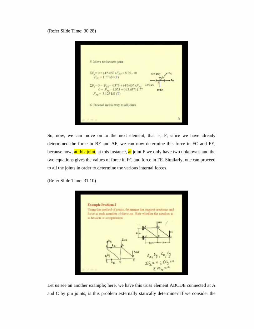
(Refer Slide Time: 30:28)
So, now, we can move on to the next element, that is, F; since we have already
determined the force in BF and AF, we can now determine this force in FC and FE,
because now, at this joint, at this instance, at joint F we only have two unknowns and the
two equations gives the values of force in FC and force in FE. Similarly, one can proceed
to all the joints in order to determine the various internal forces.
(Refer Slide Time: 31:10)
Let us see an another example; here, we have this truss element ABCDE connected at A
and C by pin joints; is this problem externally statically determine? If we consider the

free body diagram of the complete truss element, that is, ABCDE and external forces of
6 kilo Newton applied at B and 3 kilo newton applied at E. At A, we have a pin
connection, and so, we have to determine two components of reaction A y and A x and at
C, we again have a pin reaction, thereby we have to determine the two components of
reaction C y and C x. So, the total number of unknowns at hand is A x, A y, C x, C y, but
we know that for this truss to be in equilibrium, if you write the force summation
equation, sigma F x equal to 0 sigma F y equal to 0 and sigma moment, let us say about a
point A, to be equal to 0.
These three equations can be used to determine only three of these unknowns. So, how
do we proceed? If we see that, if we remove this truss from its support, actually this
element CD is no longer rigid and is free to rotate about this joint D.
(Refer Slide Time: 33:53)
So, we cannot consider the complete truss to be rigid, but rather we have to consider the
two individual elements, that is, ABDE and the single element CD as two separate rigid
bodies. So, now, for each of this free body diagram, let us depict what are the
unknowns. At A, we do not know the two components of reactions, that is, A y and A x;
at D, we do not know the two components again, that is, D x and D y; if we come to this
element CD at C, it is connected by a pin; so, again we have two unknown components
of reaction, that is C y and C x and at D, we have D y and D x. We can observe that since

this D is the common joint between this element and this element, the forces are equal
and opposite.
So, what are the unknowns? We have A x , A y , D x , D y from this free body diagram,
and C x , C y from this free body diagram, because this D x and D y are equal in
magnitude and only opposite in direction to these two forces.
So, now, we see that we have six number of unknowns to be determined and each of the
free body diagram - if I designate this as free body diagram 1 and this as free body
diagram 2, FBD 2 - then from these two diagrams we have three plus three, that is six
equations and we have six unknowns to be determined. So, this problem now becomes
statically determinate. Once we have determined these external reactions and the force at
D, now we can use the method of joints to determine all the internal forces.
(Refer Slide Time: 37:02)
Let us see a three-dimensional truss example. Here you see a three-dimensional truss
ABCDE subjected to an external load of 2L at A and a load of L at D, and it is supported
by a pivot joint at B, and by slender members at E and C as well as at D. First, let us see
if this problem is statically determinate, externally. In order to do that, we have to
construct the free body of this truss; since at B, the truss is pinned, it arrests all
translation and thereby provides three components of reaction B x, B y and B z. And at
C, we have an slender vertical rod, thereby the member can only support a vertical
reaction, and thus offers only a vertical component of reaction C z; same is the case at

joint E, where we again have a slender member. At D, we have a horizontal member
along the y direction, and thereby, we have a single component of reaction D y.
So, we see that we have total of three plus three, six unknown reaction to be determined
and from the free body diagram of the complete truss, we have six equations, that is,
three force summation equations and three moment summation equation, thereby it is
possible to determine all the reactions. But let us see this problem; here we are just
interested to find force in the member BD. So, in order to determine the force in this
member BD, we can either consider the equilibrium of this joint or equilibrium of this
joint. And the only criteria that has to be satisfied is that since in 3 D from the force
summation equation, we can determine three unknowns, at a joint, we should only joint
three unknown components of force to be determined.
If we see the joint at D, we have to determine three unknown reactions, and then, the
various forces that is BC, BD, BE and BA. At D, we have to determine only one external
reaction DY and the forces in the members AD, CD, BD, ED, etcetera. At D, we see that
we have to determine, four members forces in four members, and in order to do that, we
need to know at least one force, if we have to use the equilibrium equations of joint D.
So, we see that if we can determine the force in this member CD, then the problem can
be solved. And in order to find the force in member CD, we have to know this external
reaction C z. So, we see that in order to determine the force in this member BD, it is
sufficient to determine these two external reactions, that is D y and C z. So, this can be
determined by using the moment summation equation. So, here we use the moments
about this axis BE, which provides this reaction C z, and the moment summation about
the vertical axis passing through B, that is, B z, results in determining this reaction D y;
both have turned out to be L.

(Refer Slide Time: 41:55)
Now, we can proceed to determine the force CD by considering the equilibrium of this
joint C. So, here you see the joint C with various forces that is FCB, FCA and FCD. The
direction cosines of these forces can be determined from the geometry of the truss.
Particularly for determining this direction cosine of the member CA, you have to
consider the geometry of the truss, and it has been determined to be 0.359 in the negative
direction of I, and 0.35 times in the j direction, and 0.862 in the k direction. So, this gives
the unit vector along this member CA. So, the force in this member CA is equal to the
magnitude of the force times the unit vector along the direction of the member. And
since now, we have determined all these forces in their vector form, now we can use the
equilibrium equation to determine the forces.
So, the equilibrium equation sigma F equal to 0, results in three scalar equations, one for
i j and k, one each for i, j and k. Since we are interested in determining this force in CD,
we can solve these two equations to determine the force in CD and it has been found to
be 0.417 times of L.

(Refer Slide Time: 43:58)
Now, that we have determined this force, we can move to this joint D. The various forces
both internal as well as the external reaction and the externally applied load are shown in
this picture. The direction cosines of various forces can be obtained from the geometry of
the truss. And we have already determined the magnitude of this force in member CD
and so only we have three unknowns, that is, the force in BD, force in the element ED
and force in the member BA to be determined.
And these can be determined from the force summation equation. The three scalar
components, gives the three equations and one can determine the force in the member
BD. So, this example shows the complete working procedure by the method of joints for
solving the problem of determining the internal forces in the trusses.
(Refer Slide Time: 45:04)
Sometimes special conditions help in expediting the analysis of the truss. So, if we can
determine such special loading conditions, a priori to solving the problem, it makes the
solution procedure simpler as well as gives scope for doing additional checks.
(Refer Slide Time: 45:50)
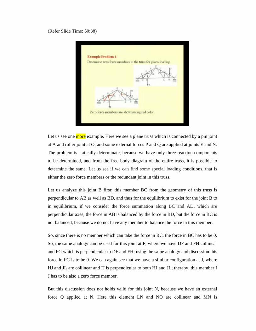
One kind of special loading is known as the zero force members and this picture depicts
a truss element that is ABCDEF, connected by a roller at A, and by a pin joint at F, and
various externally applied loads like F 1, F 2, F 3 at joints C, E and G.

Let us consider this equilibrium of this joint at B, we have this force in the member BC,
FBC; since the member is horizontal, the forces along the x direction, and the force in
the member AB, that is, FAB is along the direction. So, if a force exists in this member
AB, then it will have a vertical component and the horizontal component. The horizontal
component of this force AB can be balanced by a force that exists in, let us say the
member BC, but the vertical component of this force FAB cannot be balanced, because
this member BC, which is horizontal, cannot support any vertical component of the
force.
Since the vertical component this force cannot be balanced, the force in this member has
to be 0, and if the force in this member AB is 0, then there is no horizontal component of
the force AB, and thereby, the force in BC has to be also 0. So, we find that the forces in
the member BC, as well as the force in the member AB are 0, because of this geometric
configuration.
Let us also see the joint D which occurs in the same truss. Here, we have two elements
CD and DE which are horizontal, and we have this element DG which is inclined. For
equilibrium to exist and for this joint D to be in equilibrium, the vertical component of
this force BG has to be balanced, and since both the members CD as well as DE are
horizontal and cannot take the vertical component of the force, the forces in the member
BG has to be 0, and the force in member CD, is balanced by the force in member BE. So,
it is possible to determine using this analogy, the various zero force members, if it exists
in a truss.

(Refer Slide Time: 45:50)
There is an another special configuration that we call it has the redundant joint
configuration; that is, in a redundant joint, the forces of the constituent members are not
shared; like here you see this black member and the blue member which are collinear, as
well as the red member and the pink member which are again collinear, connected at this
joint. But we see that for equilibrium there is no load sharing; that is, the force in this
member F 2 is balanced by force in this blue member F 4 and the force in this red
member F 1 is balanced by the force in this pink member that is F 3.
So, this joint does not takes part in the load sharing; so thereby, the presence of this joint
is a redundancy and it does not helps in load sharing between the members. So, if we can
determine such special conditions that exist in a truss, it generally expedites the process
of determining the internal forces.
(Refer Slide Time: 50:38)
Let us see one more example. Here we see a plane truss which is connected by a pin joint
at A and roller joint at O, and some external forces P and Q are applied at joints E and N.
The problem is statically determinate, because we have only three reaction components
to be determined, and from the free body diagram of the entire truss, it is possible to
determine the same. Let us see if we can find some special loading conditions, that is
either the zero force members or the redundant joint in this truss.
Let us analyze this joint B first; this member BC from the geometry of this truss is
perpendicular to AB as well as BD, and thus for the equilibrium to exist for the joint B to
in equilibrium, if we consider the force summation along BC and AD, which are
perpendicular axes, the force in AB is balanced by the force in BD, but the force in BC is
not balanced, because we do not have any member to balance the force in this member.
So, since there is no member which can take the force in BC, the force in BC has to be 0.
So, the same analogy can be used for this joint at F, where we have DF and FH collinear
and FG which is perpendicular to DF and FH; using the same analogy and discussion this
force in FG is to be 0. We can again see that we have a similar configuration at J, where
HJ and JL are collinear and IJ is perpendicular to both HJ and JL; thereby, this member I
J has to be also a zero force member.
But this discussion does not holds valid for this joint N, because we have an external
force Q applied at N. Here this element LN and NO are collinear and MN is
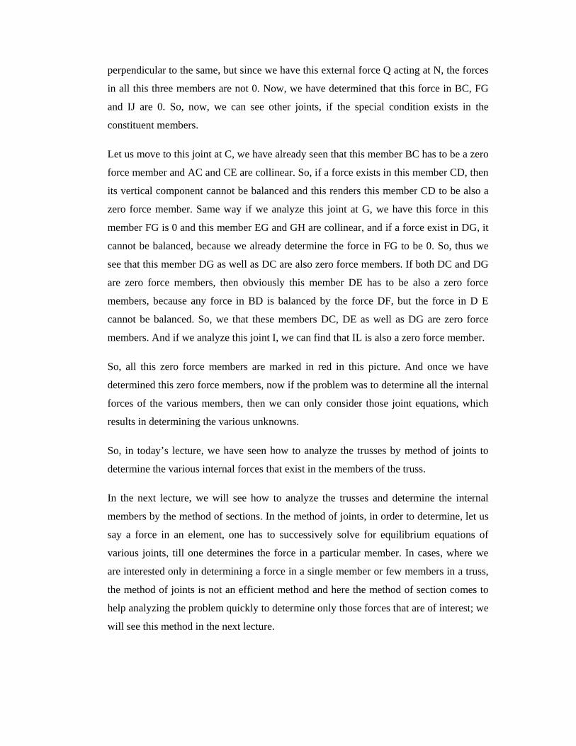
perpendicular to the same, but since we have this external force Q acting at N, the forces
in all this three members are not 0. Now, we have determined that this force in BC, FG
and IJ are 0. So, now, we can see other joints, if the special condition exists in the
constituent members.
Let us move to this joint at C, we have already seen that this member BC has to be a zero
force member and AC and CE are collinear. So, if a force exists in this member CD, then
its vertical component cannot be balanced and this renders this member CD to be also a
zero force member. Same way if we analyze this joint at G, we have this force in this
member FG is 0 and this member EG and GH are collinear, and if a force exist in DG, it
cannot be balanced, because we already determine the force in FG to be 0. So, thus we
see that this member DG as well as DC are also zero force members. If both DC and DG
are zero force members, then obviously this member DE has to be also a zero force
members, because any force in BD is balanced by the force DF, but the force in D E
cannot be balanced. So, we that these members DC, DE as well as DG are zero force
members. And if we analyze this joint I, we can find that IL is also a zero force member.
So, all this zero force members are marked in red in this picture. And once we have
determined this zero force members, now if the problem was to determine all the internal
forces of the various members, then we can only consider those joint equations, which
results in determining the various unknowns.
So, in today’s lecture, we have seen how to analyze the trusses by method of joints to
determine the various internal forces that exist in the members of the truss.
In the next lecture, we will see how to analyze the trusses and determine the internal
members by the method of sections. In the method of joints, in order to determine, let us
say a force in an element, one has to successively solve for equilibrium equations of
various joints, till one determines the force in a particular member. In cases, where we
are interested only in determining a force in a single member or few members in a truss,
the method of joints is not an efficient method and here the method of section comes to
help analyzing the problem quickly to determine only those forces that are of interest; we
will see this method in the next lecture.


