ENERGY STORAGE SAFETY STRATEGIC PLAN
83
ENERGY STORAGE SAFETY STRATEGIC PLAN U.S. Department of Energy Office of Electricity Delivery and Energy Reliability December, 2014
Transcript of ENERGY STORAGE SAFETY STRATEGIC PLAN

ENERGY STORAGE SAFETY STRATEGIC PLAN
U.S. Department of Energy Office of Electricity Delivery and Energy Reliability
December, 2014

1
Energy Storage Safety Strategic Plan
U.S. Department of Energy
Office of Electricity Delivery and Energy Reliability
December, 2014

2
Acknowledgements
The Department of Energy Office of Electricity Delivery and Energy Reliability would like to
acknowledge those who participated in the 2014 DOE OE Workshop for Grid Energy Storage
Safety (Appendix A), as well as the core team dedicated to developing this report to address the
safety of grid energy storage systems: Sean J. Hearne, Summer Ferreira, Mark Smith, Abbas
Akhil & Amanda Spinney (Sandia National Laboratories); Landis Kannberg, Vincent Sprenkle,
& David Conover (Pacific Northwest National Laboratory); Matthew Paiss (International
Association of Fire Fighters); Michael A. Stosser (Sutherland Asbill & Brennan LLP); Robert S.
Fleishman (Morrison & Foerster LLP).
Additionally, the Department of Energy Office of Electricity Delivery and Energy Reliability
would like to acknowledge the generous efforts made to review the document from all the
members of the 2014 DOE OE Workshop for Grid Energy Storage Safety (Appendix A), the
members of the EPRI ESIC Working Group 3, and specifically Ken Willette (National Fire
Protection Agency), Ryan Franks (National Electrical Manufacturers Association), Dean E.
Philips & Conrad Eustis (Electric Power Research Institute), Jim Arseneaux (Beacon Power,
LLC), Davion Hill (DNV-GL), Hiroyuki Kubo (Incorporated Administrative Agency, National
Institute of Technology and Evaluation of Japan), and Nanamori Yasuyuki (Mitsubishi Research
Institute, Inc.).
Dr. Imre Gyuk Program Manager Energy Storage Research Office of Electricity Delivery and Energy Reliability U.S. Dept. of Energy

3
Contents Acknowledgements ..................................................................................................................... 2
Executive Summary .................................................................................................................... 6
Science-based Safety Validation Techniques: ......................................................................... 8
Incident Preparedness: ............................................................................................................. 9
Safety Documentation: ............................................................................................................ 9
1.0 Introduction and Motivation........................................................................................... 10
2.0 Current State of Energy Storage Technologies .............................................................. 12
2.1 Pumped Hydro Storage .................................................................................................... 13
2.2 Compressed Air Energy Storage (CAES) ....................................................................... 13
2.3 Superconducting Magnetic Energy Storage (SMES) ...................................................... 14
2.4 Flywheels ......................................................................................................................... 14
2.5 Capacitors ........................................................................................................................ 14
2.6 Batteries ........................................................................................................................... 15
3.0 State of Safety Validation in the U.S. ............................................................................ 15
4.0 Key Aspects for Addressing Energy Storage Safety ...................................................... 18
5.0 Validation Techniques.................................................................................................... 19
5.1 Current Validation Techniques ........................................................................................ 19
5.2 Areas of Interest in Safety Validation ............................................................................. 21
5.3 Materials Science R&D ................................................................................................... 23
5.4 Electrolyte Safety R&D ................................................................................................... 25
5.5 Engineering controls and system design ......................................................................... 30
5.6 Testing and Analysis ....................................................................................................... 32
5.7 Modeling .......................................................................................................................... 34
5.8 Summary .......................................................................................................................... 41

4
6.0 Incident Preparedness ..................................................................................................... 41
6.1 Current Conditions .......................................................................................................... 41
6.2 Incident Preparedness ...................................................................................................... 43
6.3 Incident Response ............................................................................................................ 46
6.4 Gap Areas ........................................................................................................................ 47
7.0 Safety Documentation .................................................................................................... 50
7.1 Overview of the CSR Deployment Process and Involved Stakeholders ......................... 52
7.2 Compliance with Land Use Permitting and Environmental Requirements ..................... 57
7.3 Legal Framework for Energy Storage System Safety ..................................................... 60
8.0 Implementation of Goals to Reach Desired End States ................................................. 63
8.1 ESS Safety Technology .............................................................................................. 65
8.2 Risk Assessment and Management ............................................................................ 66
8.3 Incident Response ....................................................................................................... 67
8.4 Codes, Standards and Regulations.............................................................................. 68
Appendix ................................................................................................................................... 70
A. List of DOE OE Energy Storage Safety Workshop Participants and Affiliations ..... 70
B. Abridged List of Relevant Codes, Standards and Regulations ................................... 73
C. References for Validation Techniques ....................................................................... 75
Acronym List............................................................................................................................. 78

5
Table of Figures
Figure 1. Percentage of Energy Storage Systems Deployed......................................................... 11
Figure 2. Maturity of Electricity Storage Technologies ............................................................... 13
Figure 3. Example of Possible Testing Arrangement for a Battery-Based Storage Product ........ 35
Figure 4. Experimental Setup of Gas Evolution and Release with Infrared Absorption .............. 36
Tables
Table 1. Range of Storage Technology and Size ........................... Error! Bookmark not defined.
Table 2. Common Tests to Assess Risk from Electrical, Mechanical, and Environmental
Conditions ...................................................................................................................... 31
Table 3. Tests under Development for Specific Technologies ..................................................... 38

6
Executive Summary
Energy storage is emerging as an integral component to a resilient and efficient grid through a
diverse array of potential application. The evolution of the grid that is currently underway will
result in a greater need for services best provided by energy storage, including energy
management, backup power, load leveling, frequency regulation, voltage support, and grid
stabilization.1 The increase in demand for specialized services will further drive energy storage
research to produce systems with greater efficiency at a lower cost, which will lead to an influx
of energy storage deployment across the country. To enable the success of these increased
deployments of a wide variety of storage technologies, safety must be instilled within the energy
storage community at every level and in a way that meets the need of every stakeholder.
In 2013, the U.S. Department of Energy released the Grid Energy Storage Strategy2, which
identified four challenges related to the widespread deployment of energy storage. The second
of these challenges, the validation of energy storage safety and reliability, has recently garnered
significant attention from the energy storage community at large.3 This focus on safety must be
immediately ensured to enable the success of the burgeoning energy storage industry, whereby
community confidence that human life and property not be adversely affected is instilled from
the earliest stages.4 The resultant increase in consumer confidence in energy storage will ease
and facilitate the expansion of energy storage’s deployment, allowing for the electric grid to
meet the ever-expanding needs of the consumer.
The safe application and use of energy storage technology knows no bounds. An energy storage
system (ESS) will react to an external event, such as a seismic occurrence, regardless of its
location in relation to the meter or the grid. Similarly, an incident triggered by an ESS, such as a
fire, is ‘blind’ as to the location of the ESS in relation to the meter. This document will address
grid-side safety, while recognizing that the efforts undertaken will apply to other ESS
applications, regardless of deployment location.
1 Grid Energy Storage Strategy. U.S. Department of Energy, Dec. 2013. 2 Grid Energy Storage Strategy. U.S. Department of Energy, Dec. 2013, p. 5. 3 DOE OE Energy Storage Safety Workshop, Albuquerque, NM. 2014. 4 Gyuk, Imre. “Energy Storage Safety: An Essential Concern.” DOE OE Energy Storage Safety Workshop, Feb. 2014.

7
Each stakeholder group has a specific motivation for pursuing energy storage safety.
Manufacturers are producing an increasing number of systems and system components to meet a
growing demand for energy storage and must be confident in the safety of these products.
Regulators are required to address the system installations in terms of application space,
ownership, risk, and potential litigation. Insurers must develop applicable risk assessments and
first responders must be able to safely and successfully respond to any incidents.
The actions, responsibilities, and concerns of each stakeholder group are all interconnected. The
science-based techniques used to validate the safety of energy storage systems must be
documented a relevant way, that includes every level of the system and every type of system.
These science-based safety validation techniques will be used by each stakeholder group to
ensure the safety of each new energy storage system deployed onto the grid. Once researchers
establish science-based validation and mitigation techniques, manufacturers will have guidelines
that support the construction of systems that can be validated as safe. With standardized
guidelines for safe component and system construction, regulators and insurance companies will
be able to fully assess the risk of owning and insuring each system. Additionally, first
responders must be included in the discussion to ensure that all areas of potential failure are
identified and the best mitigation strategies are developed, spanning the chemistries and
materials choices through components, module layouts and deployment.
Safety of any new technology can be broadly viewed as having three intimately-linked
components: 1) a system must be engineered and validated to the highest level of safety possible;
2) techniques and processes must be developed for responding to incidences if they do occur;
and 3) the best practices and system requirements must then be reflected standardized safety
determinations in the form of codes, standards and regulations (CSR) so that there is uniform,
written guidance for the community to follow when designing, building, testing and deploying
the system. When successful, CSRs apply the best-known practices for safety to a system. The
predictability of real-time operation, and therefore safety, is improved when systems are
designed with similar system requirements.
A thread of complexity running through all three of the components of safety (i.e. validation
techniques, incident response and safety documentation) is an ever increasingly diverse portfolio
of technologies and the wide array of potential deployment environments. To provide the

8
greatest impact, the validation techniques discussion presented in this document focuses
primarily on batteries, with some discussion of flywheels, as these two technologies are
undergoing rapid evolution and growth in the deployment.
Safety documentation provides guidance to the energy storage community in the form of codes,
standards, and regulations. Two crucial considerations must be taken into account surrounding
the adoption and administration of standards. First, system owners must understand which codes
and standards are necessary before and after the installation of energy storage systems. Second,
the parties responsible for the oversight, regulation and response must be identified. This
identification will ensure a clear path of communication between owners, regulators and
responders to best prevent any potential incident. Both of these considerations will make the
installation process efficient and cost effective for owners, ensure that all responsible parties are
communicating to best avoid an incident, and ensure effective incident response. They will also
clearly outline risk, which will enable the application of effective risk mitigation and risk
management measures. These safety documents will be informed by the science-based
validation techniques established through research and development. This work will provide the
basis for the protocols and design in the codes and standards and will meet the needs to minimize
loss and protect the first responders.
The goal of this DOE Office of Electricity Delivery and Energy Reliability (OE) Strategic Plan
for Energy Storage Safety is to develop a high-level roadmap to enable the safe deployment
energy storage by identifying the current state and desired future state of energy storage safety.
To that end, three interconnected areas are discussed within this document:
Science-based Safety Validation Techniques:
• Most of the current validation techniques that have been developed to address energy
storage safety concerns have been motivated by the electric vehicle community, and are
primarily focused on Li-ion chemistry and derived via empirical testing of systems.
Additionally, techniques for Pb-acid batteries have been established, but must be revised
to incorporate chemistry changes within the new technologies. Moving forward, all
validation techniques must be expanded to encompass grid-scale energy storage systems,
be relevant to the internal chemistries of each new storage system and have technical
bases rooted in a fundamental-scientific understanding of the mechanistic responses of

9
the materials. Experimental research and development efforts to inform models from cell
to system scale must be the basis of the next generation of validation techniques needed
for the new grid-scale storage systems, as empirically derived tests are not sufficient to
ensure safety.
Incident Preparedness:
• First responders will be called upon to respond to an incident should it occur to protect
the lives of anyone involved and minimize the damage to assists. Therefore, there must
be a deliberate and concerted effort to engage the first responder community early in the
design and siting of energy storage systems so that proper mitigation techniques can be
developed and systems designed to improve the overall safety and ability to quickly and
safety resolve the incident. This must include the development of techniques to
extinguish any fires if they were to occur and respond to the variety of non-fire incidents
that may require fire department response, developing site specific training for first
responders, improved systems design, and the development of incident response plans.
All of these must be based on the scientific understanding of the systems, materials and
processes and embodied in the criteria in codes, standards and regulations.
Safety Documentation:
• Currently, safety-related criteria in the form of codes, standards and regulations that
apply to system components and deployments need to be updated to reflect the growing
verity of storage technologies. This documentation is not specific to the multitude of
chemistries and assembled modules that compose the new storage systems being
deployed. As a result, CSR are inefficient and ineffective and must be updated and
standardized.
This document additionally highlights four key elements around which DOE efforts will revolve.
DOE programmatic efforts will focus on four elements:
• ESS safety technology
• Risk assessment and management
• Incident response

10
• Codes, standards and regulations
To ensure the thorough establishment of the scientific and technical basis for ESS safety in each
technology, information concerning all safety hazards must be gathered and categorized. Testing
and analysis procedures will then be defined in such a way that enables stakeholders to use them
for each major class of ESS. Within risk assessment and management, the goal is that the
framework and methodologies for assessing and managing deployment risk for ESS are accepted
and adopted by industrial and regulatory stakeholders. Towards this end, current frameworks will
be catalogued, and a model risk framework will be identified for specific ESS technologies. The
ultimate goal for first and second responders is the complete awareness of hazards and the ability
to address them in the field. Finally, it is the goal that codes, standards and regulations enable
the deployment of safe ESS. Gaps in CSR that require additional technical research,
development, and demonstration will be identified and addressed.
1.0 Introduction and Motivation
Grid energy storage systems are “enabling technologies”; they do not generate electricity, but
they do enable critical advances to modernize the electric grid. For example, there have been
numerous studies that have determined that the deployment of variable generation resources will
impact the stability of grid unless storage is included.5 Additionally, energy storage has been
demonstrated to provide key grid support functions through frequency regulation.6 The diversity
in the performance needs and deployment environments drive the need of a wide array of storage
technologies. Often, energy storage technologies are categorized as being high-power or high-
energy. This division greatly benefits the end user of energy storage systems because it allows
for the selection of a technology that fits an application’s requirements, thus reducing cost and
maximizing value. For example, frequency regulation requires very rapid response, i.e. high-
power, but does not necessarily require high energy. By contrast, load-shifting requires very
high-energy, but is more flexible in its power needs. Uninterruptible power and variable
generation integration are applications where the needs for high-power versus high-energy fall
5 Denholm, Paul; Ela, Erik; Kirby, Brendan; Milligan, Michael. “The Role of Energy Storage with Renewable Electricity Generation.” National Renewable Energy Laboratory Technical Report: NREL/TP-6A2-47187. Jan 2010. 6 Arseneaux, Jim. “20 MW Flywheel Frequency Regulation Plant (Hazle Spindle).” Beacon Power, LLC. EESAT Conference. Oct 2013.

11
somewhere in between the aforementioned extremes. Figure 1 shows the current energy storage
techniques deployed onto the North American grid.7 This variety in storage technologies
increases the complexity in developing a single set of protocols for evaluating and improving the
safety of grid storage technologies and drives the need for understanding across length scales,
from fundamental materials processes through full scale system integration.
Figure 1. Percentage of Battery Energy Storage Systems Deployed8
The variety of deployment environments and application spaces compounds the complexity of
the approaches needed to validate the safety of energy storage systems. The difference in
deployment environment impacts the safety concerns, needs, risk, and challenges that affect
stakeholders. For example, an energy storage system deployed in a remote location will have
very different potential impacts on its environment and first responder needs than a system
deployed in a room in an office suite, or on the top floor of a building in a city center. The closer
the systems are to residences, schools, and hospitals, the higher the impact of any potential
incident regardless of system size. Therefore, it is critical that the safety risk of each system be
mitigated and the appropriate responder preparedness tailored to the specific risks, exposured
7 DOE Global Energy Storage Database. July 2014. 8 “Total Megawatt Percentage” includes contracted batteries as well as batteries with verification in progress. “Other” includes ultrabatteries, nickel ion, nickel cadmium, lithium polymer, lithium nickel cobalt aluminum, sodium nickel chloride, lithium ferrous phosphate, lead carbon, hybrid, and aqueous hybrid ion.
Lead acid 28.20%
Lithium ion 41.79%
Sodium sulfur 8.17%
Flow 2.62%
Other 14.38%
Lithium Iron Phosphate
4.84%
Total Megawatt Percentage
12
population and infrastructure, which reduces the potential losses and is key in determining the
overall cost of ownership.
The discussion within this document explores the current landscape of energy storage
deployments and technologies and identifies specific areas in validation techniques, incident
response and safety codes, standards and regulations (CSR) where the community should focus
its efforts. Ultimately, it is the goal of this strategic plan to lay the groundwork necessary to
ensure the safety of energy storage deployments and instill confidence in the community of
stakeholders who depend on an efficient, reliable and resilient electric grid.
2.0 Current State of Energy Storage Technologies
Each storage technology has unique performance characteristics that make it optimally suitable
for certain grid services; however, the technologies are each at different maturity levels and are
each deployed in varying amounts. These differences must be taken into consideration when
addressing safety because the level of risk increases as the level of maturity decreases or the
level of deployment increases. The different levels of maturity and deployment also illustrate
which systems must immediately be validated as safe. As per the DOE Grid Strategy, “the
categorization of ‘deployed,’ ‘demonstrated,’ and ‘early stage,’ is often blurred, and changes
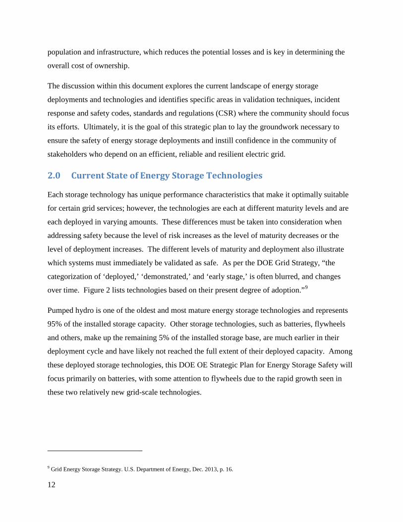
over time. Figure 2 lists technologies based on their present degree of adoption.”9
Pumped hydro is one of the oldest and most mature energy storage technologies and represents
95% of the installed storage capacity. Other storage technologies, such as batteries, flywheels
and others, make up the remaining 5% of the installed storage base, are much earlier in their
deployment cycle and have likely not reached the full extent of their deployed capacity. Among
these deployed storage technologies, this DOE OE Strategic Plan for Energy Storage Safety will
focus primarily on batteries, with some attention to flywheels due to the rapid growth seen in
these two relatively new grid-scale technologies.
9 Grid Energy Storage Strategy. U.S. Department of Energy, Dec. 2013, p. 16.

13
Figure 2. Maturity of Electricity Storage Technologies
.
2.1 Pumped Hydro Storage
Pumped hydro is so established as a deployed storage technology that this is not a focus
technology for addressing safety concerns. With over 100 GW of installed capacity in the world,
and the first hydroelectric plants opening in the 1800s, the technology is well understood without
large uncertainty remaining concerning its safety and reliability.
2.2 Compressed Air Energy Storage (CAES)
Although CAES is an earlier stage technology, the mechanics of conventional CAES have
characteristics analogous to many commercial industrial processes, such as conventional piping
and fittings. Established safety codes address the above-ground CAES pressure vessel concerns
which are well mitigated with pressure relief valves implemented at pressures equal to 40% of
the rupture pressure in steel vessels and 20% of the rupture pressure for fiber-wound vessels, as
defined by code. Such established safety protocols in industry result in reduced concerns and
uncertainly with respect to safety in CAES deployments.
14
2.3 Superconducting Magnetic Energy Storage (SMES)
SMES technology uses a superconducting coil to store DC current. As an early stage
technology, it has not proven itself to be a viable piece of the bulk storage market for deployed
technologies. As such, is not addressed in this strategy.
2.4 Flywheels
Though flywheels are relative newcomers to the grid energy storage arena, they have been used
as energy storage devices for centuries with the earliest known flywheel being from 3100 BC
Mesopotamia. Grid scale flywheels operate by spinning a rotor up to tens of thousands of RPM
storing energy in a combination of rotational kinetic energy and elastic energy from deformation
of the rotor. These systems typically have large rotational masses that in the case of a
catastrophic radial failure need a robust enclosure to contain the debris. However, if the mass of
the debris particles can be reduced through engineering design, the strength, size and cost of the
containment system can be significantly reduced. For example, laminated flywheels where the
bonding strength of the layers is lower that the tensile strength within a layer will “unwind”
rather than throw off large arc sections of the rotor material. The engineering designs and safety
factors in containing flywheels are not currently widely established by the CSRs and require
further research. Current safety validation testing involves burst testing to probe containment
integrity, loss-of-vacuum testing, overspeed testing of systems, as well as fatigue testing of
sample materials. 10
2.5 Capacitors
Electrochemical capacitors prompt similar concerns in terms of the safety of the stored energy
within an electrochemical device and failures of devices. They are not therefore addressed
independently here, but they do deserve attention in understanding and addressing safety for grid
storage. Validation techniques can be considered in the context of approaches taken for battery
safety.
10Flynn, M. M., Zierer J. J., Thompson, R. C. “Performance Testing of a Vehicle Flywheel Energy System” SAE Technical Paper Series. 2005. http://www.utexas.edu/research/cem/Energy_storage_photos/2005_Performance%20Testing%20of%20a%20Vehicular%20Flywheel%20Energy%20System%202005-01-0809.pdf

15
Electrostatic and electrolytic capacitors are used in board design and are a very common cause of
faults that can lead to cascading failure resulting in voltage and or current surges and overcharge
of storage devices or temperature rises that can lead to ignition of flammable materials either
within the capacitor or adjacent components.
2.6 Batteries
As electrochemical technologies, battery systems used in grid storage can be further categorized
as redox flow batteries, hybrid flow batteries, and secondary batteries without a flowing
electrolyte. For the purposes of this document, vanadium redox flow batteries and zinc bromine
flow batteries are considered for the first two categories, and lead-acid, lithium ion, sodium
nickel chloride and sodium sulfur technologies in the latter category. As will be discussed in
detail in this document, there are a number of safety concerns specific to batteries that should be
addressed, e.g. release of the stored energy during an incident, cascading failure of battery cells,
and fires.
3.0 State of Safety Validation in the U.S.
Several significant issues in the current state of safety validation that must be addressed,
including: passive safety plans, reactionary safety approaches, and ineffective first response
procedures. First, the typical safety plan is passive, i.e. addressing each deployed system on a
case-by-case basis rather than having global standards and protocols for safety. Historically,
technology has typically led regulations, i.e. each installation of megawatt-sized, battery-based
energy storage systems since the 1980s has marked a technological milestone in the development
and understanding of the operational characteristics of such large-scale battery systems. Because
each installation was unique in size, functionality, and design, the unifying safety validation
techniques and national CSR for the integrations and use of full systems was absent. While there
are substantial CSR in existence for individual components within a storage system, current
safety documents must now be updated to address the entire integrated system in order to fully
validate its operational safety. Overall system safety is still determined on an installation-by-
installation basis by the system vendor (either the system manufacturer or the system installer)
who is charged with satisfying owner requests and meeting any applicable CSR on behalf of the
owner. The CSR currently available and directives guide the approach to safety of systems on
the grid side of the meter. However, fire marshals typically have little oversight of activities on

16
the grid side of the meter, which is typically under the jurisdiction of the public utilities
commission. On the customer side, a similar approach is found, but is based on enforcement of
adopted CSR by state and local agencies. This individualized approach for evaluating safety is
the current modus operandi and ultimately hinders the time and cost of deploying systems.
Second, safety approaches are reactionary instead of proactive and predictive, thus unnecessarily
increasing costs with irrelevant and ineffective techniques. Energy storage systems
manufacturers, owners, and installers will use validation techniques for new systems based on
previous installation experience, disregarding differences in system type, battery chemistry, total
capacity, or deployment environment. The result of this approach is that the validation
techniques are not comprehensive, though substantial amounts of money and time are spent to
initiate them. An example of ineffective safety validation can be found in method used by the
Puerto Rico Electric Power Authority (PREPA) to install a 20 MW/17 MWh spinning
reserve/frequency regulation battery system in 1994.11 This installation was patterned after a
similarly-sized, flooded-cell, lead-acid battery system installed at the West Berlin Electric Utility
Company (BEWAG) in Berlin in 1986.12 Even though the PREPA installation was fashioned
after the BEWAG system, the local fire marshal in San Juan determined that the mandatory
safety requirements at the PREPA installation were significantly different. Differences in the
battery chemistry, the application space, and the deployment environment between the two
systems were not accounted for before PREPA was installed. This initial oversight resulted in
costly additional risk mitigation measures. PREPA was required to provide a structural design
on the second floor, which housed the battery, as a virtual swimming pool to hold all the water
required to extinguish a potential fire. In addition, PREPA was required to store on site a large
quantity of water for firefighting, along with its necessary pumping infrastructure. The
additional cost and space requirements, caused by the altered structural design of the building,
dramatically increased the deployment cost.
System owners are often required to establish a safety margin based on their best engineering
guess rather than on scientifically derived validation techniques developed from an
11 Farber-DeAnda, Mindi. Boyes, John D. Wenceslao, Torres. “Lessons Learned from the Puerto Rico Battery Energy Storage System.” Sandia National Laboratories, 1999. 12 Wagner, Richard. “High-power lead-acid batteries for different applications.” Journal of Power Sources, Nov. 2004. p 496.

17
understanding of the active processes and limitations of the system, as was the case with the
PREPA system. As safety validation techniques are developed, validated, and documented for
each type of storage technology in every potential deployment environment, system owners will
be able to accurately estimate the full cost of each deployed system, including the risks
associated with insuring the installation. Significant decreases in uncertainty and gains in
process efficiencies will be the results of the development and documentation of these validation
techniques. Additionally, standard validation and deployment techniques can be used to improve
the safety and knowledge base of the first responders.
The third issue is that the historic and current first response procedures have also suffered as a
result of reactive, ineffective safety validation techniques and lack of standardized
documentation. Often, due to a lack of local experience in such events, response practices are
based on events that occurred in different technologies, but were reported nationally. In the late
1980s, the question of fire safety arose concerning the lead-acid inside the containerized battery
system PM250. The enclosed container design had to allow for the safe and fail-safe venting of
hydrogen emitted during charging. Consideration was also given to how a first responder could
look inside the container to observe the interior condition without opening the container’s large
doors.13 However, neither design decision was addressed by the governing safety code, which
lacked specifications about the design of hydrogen venting or the size and location of the glass
portholes.
A reactive approach to energy storage safety is no longer viable. The number and types of
energy storage deployments have reached a tipping point with dramatic growth anticipated in the
next few years fueled in large part by major, new, policy-related storage initiatives in
California14, Hawaii15, and New York.16 The new storage technologies likely to be deployed in
13 Corey, Garth; Nerburn, William; Porter, David. “Final Report on the Development of a 250-kW Modular, Factory-Assembled Battery Energy Storage System.” Sandia National Laboratories, 1998. 14 Program Opportunity Notice: “Developing Advanced Energy Storage Technology Solutions to Lower Costs and Achieve Policy Goals,” PON-13-302. http://www.energy.ca.gov/contracts/PON-13-302/00_PON-13-302_Energy_Storage_2014-07-31.pdf 15 Hawaiian Electric. O’ahu Energy Storage System, Request for Proposals No. 072114-01. http://www.hawaiianelectric.com/vcmcontent/StaticFiles/pdf/ESS_RFP_No_072114-01.pdf 16 Reforming the Energy Vision: NYS Department of Public Service Staff Report and Proposal. Case 14-M-0101. 2014. http://www3.dps.ny.gov/W/PSCWeb.nsf/96f0fec0b45a3c6485257688006a701a/26be8a93967e604785257cc40066b91a/$FILE/ATTK0J3L.pdf/Reforming%20The%20Energy%20Vision%20%28REV%29%20REPORT%204.25.%2014.pdf

18
response to these and other initiatives are maturing too rapidly to justify moving ahead without a
unified scientifically based set of safety validation techniques and protocols. A compounding
challenge is that startup companies with limited resources and experience in deployment are
developing many of these new storage technologies. Standardization of the safety processes will
greatly enhance the cost and viability of new technologies, and of the startup companies
themselves. The modular nature of ESS is such that there is just no single entity clearly
responsible for ESS safety; instead, the each participant in the energy storage community has a
role and a responsibility. The following sections outline the gaps in addressing the need for
validated grid energy storage system safety.
4.0 Key Aspects for Addressing Energy Storage Safety
Safety of any new technology can be broadly viewed as having three intimately linked aspects,
as follows: 1) the system must be engineered and validated to the highest level of safety; 2)
techniques and processes must be developed to respond to incidents when they occur; and 3) best
practices and system requirements must then be reflected in CSR so that there is uniform,
consistent, understandable and enforceable criteria that must be satisfied when designing,
building, testing, and deploying the system. It is clear within the grid energy storage community
that specific efforts must be started or expanded to address each of these three areas.17
Specifically, as the materials, technologies, and deployment applications for storing energy are
created, new techniques and protocols must be developed to validate their safety and ensure the
risk of failure and loss is minimized. These new techniques and protocols will allow
manufacturers to design the systems to be as safe as possible, especially for the first and second
responders. These techniques will additionally be used to educate first responders on the
associated risk of responding to an incident involving the new technologies. Finally, codes,
standards, and regulations will be developed to efficiently memorialize these design rules,
response procedures and safety performance metrics to all stakeholders.
17 DOE OE Energy Storage Safety Workshop, Albuquerque, NM. 2014.

19
5.0 Validation Techniques
To date, the most extensive energy storage safety and abuse R&D efforts have been done for
Electric Vehicle (EV) battery technologies. These efforts have been limited to lithium ion, lead-
acid and nickel metal hydride chemistries and, with the exception of grid-scale lead-acid
systems, are restricted to smaller size battery packs applicable to vehicles.18 Lessons learned
from EV safety R&D can be useful in developing the grid storage energy storage safety area, and
in fact, the use of EV batteries that are beyond their automotive service life in grid storage is
emerging as a viable second life. However, the increased scale, complexity, and diversity in
technologies being proposed for grid- scale storage necessitates a comprehensive strategy for
adequately addressing safety in grid storage systems. The technologies deployed onto the grid
fall into the categories of electro-chemical, electromechanical, and thermal, and are themselves
within different categories of systems, including CAES, flywheels, pumped hydro and SMES.
This presents a significant area of effort to be coordinated and tackled in the coming years, as a
number of gap areas currently exist in codes and standards around safety in the field. R&D
efforts must be coordinated to begin to address the challenges.
5.1 Current Validation Techniques
An energy storage system can be categorized primarily by its power, energy and technology
platform. For grid-scale systems, the power/energy spectrum spans from smaller kW/kWh to
large MW/MWh systems. Smaller kW/kWh systems can be deployed for residential and
community storage applications, while larger MW/MWh systems are envisioned for electric
utility transmission and distribution networks to provide grid level services. This is in contrast to
electric vehicles, for which the U.S. Advanced Battery Consortium (USABC) goals are both
clearly defined and narrow in scope with an energy goal of 40 kWh. While in practice some EV
packs are as large as 90 kWh, the range of energy is still small compared with the grid storage
applications. This research is critical to the ability of first responders to understand the risks
posed by ESS technologies and allow for the development of safe stratagies to minimize risk and
mitigate the event.
18 Doughty, Daniel H.; Pesaran, Ahmad A. “Vehicle Battery Safety Roadmap Guidance.” National Renewable Energy Laboratory. Oct. 2012. http://www.nrel.gov/docs/fy13osti/54404.pdf

20
Table 1. Range of Storage Technology and Size
Furthermore, the diversity of battery technologies and stationary storage systems is not generally
present in the EV community. Therefore, the testing protocols and procedures used historically
and currently for storage systems for transportation are insufficient to adequately address this
wide range of storage systems technologies for stationary applications. Table 1 summarizes the
high level contrast between this range of technologies and sizes of storage in the more
established area of EV. The magnitude of effort that must be taken on to encompass the needs of
safety in stationary storage is considerable because most research and development to improve
safety and efforts to develop safety validation techniques are in the EV space.
Notably, the size of EV batteries ranges by a factor of two; by contrast, stationary storage scales
across many orders of magnitude. Likewise, the range of technologies and uses in stationary
storage are much more varied than in EV. Therefore, while the EV safety efforts pave the way in
developing R&D programs around safety and developing codes and standards, they are highly
insufficient to address many of the significant challenges in approaching safe development,
installation, commissioning, use and maintenance of stationary storage systems.
19 Mackenzie, Angus. “2013 Motor Trend Car of the Year: Tesla Model S. Motor Trend. 2013. 20 Akhil, Abbas; et al. “DOE/EPRI 2013 Electricity Storage Handbook in Collaboration with NRECA.” Sandia National Laboratories. July 2013. 21 The Tesla Motors Team. “A Supercharging Milestone.” Tesla Motors. July 2014.
Storage space Technologies Application Storage Size
(energy)
Storage Size
(power)
Electric Vehicle
Technology
Batteries (Li-ion,
NiMH, Pb-acid)
City and
highway driving 40 – 90 kWh 80 kW19
Stationary
Storage
Batteries, CAES,
flywheels,
pumped hydro
and SMES
Over 17 use
cases identified20
5 kWh – 1
GWh21 10 kW – 1 GW

21
An additional complexity of grid storage systems is that the storage system can either be built
on-site or pre-assembled, typically in shipping containers. These pre-assembled systems allow
for factory testing of the fully integrated system, but are exposed to potential damage during
shipping. For the systems built on site, the assembly is done in the field; much of the safety
testing and qualification could potentially be done by local inspectors, who may or may not be as
aware of the specifics of the storage system. Therefore, the safety validation of each type of
system must be approached differently and each specific challenge must be addressed.
5.2 Areas of Interest in Safety Validation Given the maturity and documented use of pumped hydro and CAES, batteries and flywheels are
currently the primary focus for enhanced grid-scale safety. For these systems, the associated
failure modes at grid-scale power and energy requirements have not been well characterized and
there is much larger uncertainty around the risks and consequences of failures. This uncertainty
around system safety can lead to barriers to adoption and market success, such as difficulty with
assessing value and risk to these assets, and determining the possible consequences to health and
the environment. To address these barriers, concerted efforts are needed in the following areas:
• Materials Science R&D – Research into all device components
• Engineering controls and system design
• Modeling
• System testing and analysis
• Commissioning and field system safety research
It is a notable challenge within the areas outlined above to develop understanding and confidence
in relating results at one scale to expected outcomes at another scale, or predicting the interplay
between components, as well as protecting against unexpected outcomes when one or more
failure mode is present at the same time in a system. Extensive research, modeling and
validation are required to address these challenges. Furthermore, it is necessary to pool the
analysis approaches of failure mode and effects analysis (FMEA) and to use a safety basis in
both research and commissioning to build a robust safety program. Furthermore, identifying,
responding and mitigating to any observed safety events are critical in validating the safety of
storage.
22
A holistic view with regard to setting standards to ensure thorough safety validation techniques is
the desired end goal; the first step is to study on the R&D level failure from the cell to system
level, and from the electrochemistry and kinetics of the materials to module scale behavior.
Detailed hazards analysis must be conducted for entire systems in order to identify failure points
caused by abuse conditions and the potential for cascading events, which may result in large
scale damage and/or fire. While treating the storage system as a “black box” is helpful in setting
practical standards for installation, understanding the system at the basic materials and chemistry
levels and how issues can initiate failure at the cell and system level is critical to ensure overall
system safety.
In batteries, understanding the fundamental electrochemistry and materials changes under
selected operating conditions helps guide the cell level safety. Knowledge of cell-level failure
modes and how they propagate to battery packs guides the cell chemistry, cell design and
integration. Each system has different levels of risk associated with basic electrochemistry that
must be understood; the tradeoff between electrochemical performance and safety must be
managed. There are some commonalities of safety issues between storage technologies. For
example, breeching of a Na/S (NAS) or Na/NiCl2 (Zebra) battery could result in exposure of
molten material and heat transfer to adjacent cells.22,23,24 Evolution of H2 from lead-acid cells or
H2 and solvent vapor from lithium-ion batteries during overcharge abuse could results in a
flammable/combustible gas mixture.25,26,27,28 Thermal runaway in lithium-ion (Li-ion) cells
could transfer heat to adjacent cells and propagate the failure through a battery.29 Moreover,
22 “Cause of NAS Battery Fire Incident” NGK Insulators, LTD. June, 2012. 23 A. V. Van Zyl; C.-H Dustmann (Nov. 1995). “Safety Aspects of Zebra High Energy Batteries,” in Conference Proceedings, WEVA Conference for Electric Vehicle Research, Development and Operation, November 13, 14, 15, 1995; Paris. Bruxelles, Belgium. pp. 57–63. 24 Current Status of Health and Safety Issues of Sodium/Metal Chloride (Zebra) Batteries” NREL/TP-460-25553. November, 1998. 25 A. J. Salkind, A. G. Cannone, F. A. Trumbure in “The Handbook of Batteries” D. Linden and T. B. Reddy, 3rd Edition, 2002, pp. 23.77-23.78. 26 A. W. Metwally “Generic environmental and safety assessment of five battery energy storage systems”, Electr. Power Res. Inst. 1982 27 D. P. Abraham, E. P. Roth, R. Kostecki, K. McCarthy, S. MacLaren, D. H. Doughty, “Diagnostic examination of thermally abused high-power lithium-ion cells” J. Power Sources, 161. 2006, pp. 648-657 28 G. Nagasubramanian and C. J. Orendorff, “Hydrofluoroether electrotes for lithium-ion batteries: Reduces gas decomposition and nonflammable” J. Power Sources, 196. 2011, pp. 8604-8609. 29 Mikolajczak, Celina; Kahn, Michael; White, Kevin; Long, Richard Thomas. “Lithium-Ion Batteries Hazard and Use Assessment.” Exponent Failure Analysis Associates, Inc. July 2011.

23
while physical hazards are often considered, health and environmental safety issues also need to
be evaluated to have a complete understanding of the potential hazards associated with a battery
failure. These may include the toxicity of gas species evolved from a cell during abuse or when
exposed to abnormal environments, 30,31 toxicity of electrolyte during a cell breech or spill in a
Vanadium redox flow battery (VRB),32 environmental impact of water runoff used to extinguish
a battery fire containing heavy metals.33 Flywheels provide an entirely different set of
considerations, including mechanical containment testing and modeling, vacuum loss testing,
and material fatigue testing under stress. A holistic approach needs to be taken to address all of
the cell or component level through system-level safety issues with adequate mitigations,
diagnostics, monitoring, and engineered controls.
Failure mode and effects analysis (FMEA) is conducted in installations. Research must consider
current FMEA tactics specific to stationary storage, identify weaknesses in their execution with
special attention to systems that have encountered field failure caused by abuse, and failures that
were not well controlled, leading to cascading events resulting in large scale damage and/or fire.
A comprehensive look at system level concerns with regard to failures and safety can be
approached when R&D is incorporated into the standard basis for safety.
5.3 Materials Science R&D
The topic of Li-ion battery safety is rapidly gaining attention as the number of battery incidents
increases. Recent incidents, such as a cell phone runaway during a regional flight in Australia
and a United Parcel Service plane crash near Dubai, reinforce the potential consequence of Li-
ion battery runaway events. The sheer size of grid storage needs and the operational demands
make it increasingly difficult to find materials with the necessary properties, especially the
required thermal behavior to ensure fail-proof operation. The main failure modes for these
battery systems are either latent (manufacturing defects, operational heating, etc.) or abusive
(mechanical, electrical, or thermal).
30 A. J. Salkind, A. G. Cannone, F. A. Trumbure in “The Handbook of Batteries” D. Linden and T. B. Reddy, 3rd Edition, 2002, pp. 23.77-23.78. 31 D. P. Abraham, E. P. Roth, R. Kostecki, K. McCarthy, S. MacLaren, D. H. Doughty, “Diagnostic examination of thermally abused high-power lithium-ion cells” J. Power Sources, 161. 2006, pp. 648-657. 32 “Toxicology Profile for Vanadium” U.S. Department of Health and Human Services, Public Health Service, Agency for Toxic Substances and Disease Registry. September 2012. 33 Wesoff, Eric. “Battery Room Fire at Kahuku Wind-Energy Storage Farm.” Green Tech Grid. August 2012.

24
Any of these failures can increase the internal temperature of the cell, leading to electrolyte
decomposition, venting, and possible ignition. While significant strides are being made, major
challenges remain in combating solvent flammability still remain, which is the most significant
area that needs improvement to address safety of Li-ion cells, and is therefore discussed here in
greater detail. To mitigate thermal instability of the electrolyte, a number of different approaches
have been developed with varied outcomes and moderate success. Conventional electrolytes
typically vent flammable gas when overheated due to overcharging, internal shorting,
manufacturing defects, physical damage, or other failure mechanisms. The prospects of
employing Li-ion cells in applications depend on substantially reducing the flammability, which
requires materials developments (including new lithium salts) to improve the thermal properties.
One approach is to use fire retardants (FR) in the electrolyte as an additive to improve thermal
stability. Most of these additives have a history of use as FR in the plastics industry. Broadly,
these additives can be grouped into two categories—those containing phosphorous and that
containing fluorine. A concerted effort to provide a hazard assessment and classification of the
event and mitigation when an ESS fails, either through internal or external mechanical, thermal,
or electrical stimulus is needed by the community.
Significant efforts have been made to develop tests to determine the safety margin in Li-ion
batteries in both mobile devices and vehicles. For example, significant efforts have been made
in the qualification of the response to battery cell thermal runaway, 34,35,36,37 safety response in
packs to mechanically induced failure,38 and model thermal abuse of cells.39 A comprehensive
report prepared by Exponent Failure Analysis Associate, Inc. for the Fire Protection Research
Foundation provides a detailed review of validation techniques as part of the Lithium-Ion
Batteries Hazard and Use Assessment.40 This review and its references describe the state of
34 J.R. Dahn, E.W. Fuller, M. Obrovac, U. Vonsacken. “Solid State Ionics.” 69. 1994, 265. 35 D. Belov, M.H. Yang, “Solid State Ionics.” 179. 2008, 1816. 36 D. Belov, M.H. Yang, J. “Solid State Electr.” 12, 2008, 885. 37 S.J. Harris, A. Timmons, W.J. Pitz. “J Power Sources.” 193, 2009, 855. 38 R.M. Spotnitz, J. Weaver, G. Yeduvaka, D.H. Doughty, E.P. Roth. “J Power Sources.” 163, 2007, 1080. 39 G.H. Kim, A. Pesaran, R. Spotnitz. “J Power Sources” 170, 2007, 476.

25
understanding around battery failures and research into improved safety at that time, but are
limited in the material systems and the size of the systems reviewed.
5.4 Electrolyte Safety R&D
The combustion process is a complex chemical reaction by which fuel and an oxidizer in the
presence of heat react and burn. Convergence of heat (an oxidizer) and fuel (the substance that
burns) must happen to have combustion. The oxidizer is the substance that produces the oxygen
so that the fuel can be burned, and heat is the energy that drives the combustion process. In the
combustion process a sequence of chemical reactions occur leading to fire.41 In this situation a
variety of oxidizing, hydrogen and fuel radicals are produced that keep the fire going until at
least one of the three constituents is exhausted.
5.4.1 Electrolytes
Despite several studies on the issue of flammability, complete elimination of fire in Li-ion cells
has yet to be achieved. One possible reason for the failure could be linked to lower flash point
(FP) (<38.7 °C) of the solvents.42 Published data shows that polyphosphazene polymers and
ionic liquids used as electrolytes are nonflammable.43 However, the high FP of these chemicals
is generally accompanied by increased viscosity, thus limiting low temperature operation and
degrading cell performance at sub-ambient temperatures. These materials may also have other
problems such as poor wetting of the electrodes and separator materials, excluding them from
use in cells despite being nonflammable.
Ideally, solvents would be used that have no FP while simultaneously exhibiting ideal electrolyte
behavior (see below for a number of critical properties that the electrolytes need to meet) and
would remain liquid at low temperatures down to -50 ºC or below for use in Li-ion cells. A
number of critical electrochemical and thermal properties are given below that FR have to meet
simultaneously. The tradeoffs between properties are possible but when it comes to safety there
cannot be tradeoffs.
40 Mikolajczak, Celina; Kahn, Michael; White, Kevin; Long, Richard Thomas. “Lithium-Ion Batteries Hazard and Use Assessment.” Exponent Failure Analysis Associates, Inc. July 2011. 41 S.M. Sarathy, C.K. Westbrook, M. Mehl, W.J. Pitz, C. Togbe, P. Dagaut, H. Wang, M.A. Oehlschlaeger, U. Niemann, K. Seshadri, P.S. Veloo, C. Ji, F.N. Egolfopoulos, T. Lu. “Combust Flame” 158, 2011, 2338. 42 “CRC Handbook of Chemistry and Physics”, 79th ed., edited by D. R. Lide. CRC, Boca Raton. 1998–1999. 43 S. Werner, M. Haumann, P. Wasserscheid, Annu Rev. “Chem Biomol Eng.” 1, 2010, 203

26
• High voltage stability
• Comparable conductivity to traditional electrolytes
• Lower flame propagation rate or no fire at all
• Lower self-heating rate
• Stable against both the electrodes
• Able to wet the electrodes and separator materials
• Higher onset temperature for exothermic peaks with reduced overall heat production
• No miscibility problems with co-solvents
Electrolyte non-flammability is essential for cell safety. Enhanced safety of electrolytes
containing FR additives is mostly accompanied by performance degradation including low
capacity utilization, high rate of capacity fade, or poor low temperature performance.
Additionally, some are electrochemically unstable and are consumed during cycling, becoming
unavailable for cell protection with time. Furthermore, limited information is available in the
open literature on the performance of additives in large capacity cells under actual use conditions
and subsequent abuse conditions. The higher energy density of Li-ion cells can only result in a
more volatile device, and while significant efforts have been put forth to address safety,
significant research is still needed. To improve safety of Li-ion batteries, the electrolyte
flammability needs significant advances or further mitigation is needed in areas that will contain
the effects of failures to provide graceful failures with safer outcomes in operation.
5.4.2 Additives
The most commonly accepted mechanism for fire propagation relies on a radical generation
mechanism. Ground state oxygen absorbs heat and produces energetic and extremely reactive
singlet oxygen. The identified mechanism clearly indicates that hydrogen radical and singlet
oxygen play a key role in sustaining the flame.44 This is the target for many of the materials
proposed as FR additives. If a FR material is able to sufficiently bind to the free radicals during
the reaction cascade, then propagation of the flame will be suppressed.
44 J.L. Jurs. “Development and Testing of Flame Retardant Additives and Polymers.” Rice University. 2007, 303.

27
Researchers have predominantly performed Differential Scanning Calorimetry (DSC)
measurements on electrolytes to determine thermal stability with and without the FR. The ideal
outcome is that the electrolyte with FR show very little peak in the DSC traces and even then
only at higher temperatures compared to the electrolyte without the FR.45 This observation
seems to suggest that the FR additive improves the thermal stability of the electrolyte. Others
have chosen to employ standard test procedures from the American Society for Testing and
Materials (ASTM), Underwriters Laboratories (UL), and International Electrotechnical
Commission (IEC) such as ASTM D-5306, ASTM D2863, UL-94VO, and IEC 62133 to
compute both the self-extinguishing time (SET) and the limited oxygen index (LOI) to evaluate
the flammability of the electrolytes. The shorter the SET and higher the LOI (this is the % of
oxygen needed in the O2/N2 mixture to keep the electrolyte burning for at least 60s), the less
flammable the electrolyte. In general, the electrolyte with the additives shows shorter SET and
higher LOI than the electrolyte without FR. Descriptions of the thrust of the different ASTM
and UL tests were discussed in depth by M. Otsuki, et al. 46 See Appendix A for a table of the
variety of new and novel FR materials that have been synthesized and studied as well as low
flash point electrolytes that have been developed to fight flame ignition.
In the vapor phase, the traditionally accepted mechanism is that FR decomposes, producing
phosphorous or halogen radicals that act as scavengers and react with hydrogen radicals, thereby
terminating the free radical reaction. Despite wide availability for FR materials, two primary
classes of materials have been investigated extensively for use in Li-ion batteries, which are
phosphorus-containing materials and fluorine containing materials. The phosphorous-containing
materials primarily rely on the free radical scavenging mechanism, but on rare occasion inhibit
reaction through char formation on the reactive surface. Alternately replacing hydrogen with
fluorine, the compound should be more thermally stable due to the decrease in the available
hydrogen for radical production. By eliminating the generation of hydrogen radicals,
flammability could potentially be minimized or eliminated; however, advances to date are at the
R&D scale.
45 E-G Shim, T-H Nam, J-G Kim, H-S Kim, S-I Moon. “Electrochimica Acta.” 53, 2007, 650. 46 “Lithium-Ion Batteries: Science and Technology.” Edited by M. Yoshio, R.J. Brodd, A. Kozawa. Springer-Verlag New York, LLC, 278, 2009.

28
5.4.3 Electrodes, separators, current collectors, casings, cell format headers and vent
ports
While electrolytes are by far the most critical component in Li-ion battery safety, research has
been pursued into safety considerations around the other components of the cell. These factors
can become more critical as research continues in wider ranges of chemistries for stationary
storage. Again, research to date has focused on Li-ion devices; however, insights in these
components may be leveraged in designing safer technologies across electrochemical solutions.
Within materials R&D, the exponent review describes efforts into improving safety in battery
components including safer cathodes and separators in addition to electrolytes. It also details the
state of other cell components in the context of hazards and safety; including anodes, charge
collectors, casing, and safety devices including charge interrupt devices and positive temperature
coefficient switches.47
5.4.4 Capacitors
Electrostatic capacitors are a major failure mechanism in power electronics. These
predominately fail because of the strong focus on low cost devices, and low control over
manufacturing. In response, they are used at a highly de-rated level, and often with redundant
design. When they fail they often show slow degradation with decreasing resistivity leading
eventually to shorting. Cascading failures can lead to higher consequence failures elsewhere in a
system. Arcs or cascading failures can occur. The added complexity of redundant design is a
safety risk. While there is a niche market for high reliability capacitors, they are not
economically viable for most applications, including grid storage. These devices are made of
precious metals and higher quality ceramic processing that leads to fewer oxygen vacancies in
the device.
Polymer capacitors can have a safety advantage as they can be self-healing, and therefore
graceful failure; however these are poor performers at elevated temperatures and are flammable.
Testing of capacitors currently involves putting a DC bias or increasing the temperature to
observe accelerated breakdown.
47 Mikolajczak, Celina; Kahn, Michael; White, Kevin; Long, Richard Thomas. “Lithium-Ion Batteries Hazard and Use Assessment.” Exponent Failure Analysis Associates, Inc. July 2011.

29
Currently, the low cost and low reliability of capacitors make them a very common component
that fails in devices, affecting the power electronics and providing a possible trigger for a
cascading failure. While improved reliability has been achieved in capacitors such devices are
cost prohibitive due to their manufacturing and testing. Development of improved capacitors at
reasonable cost, or design to prevent cascading failures in the event of capacitor failure should be
addressed.
5.4.5 Pumps tubing and tanks
Components specific to flow battery, and hybrid flow battery technologies have not been
researched in the context of safety for battery technology. These include components such as
pumps, tubing and storage tanks. Research from other areas that use similar components can be
a starting point, but these demonstrate how the range of components is much broader than
current R&D in battery safety.
5.4.6 Mechanical design and vacuum system
Similarly, components specific to flywheels have their own design considerations with respect to
safety. The engineering design, and safety factors in containing flywheels is not currently widely
established by CSR, and requires further research to be flushed out. Current safety validation
testing involves burst testing to probe containment integrity, vacuum loss testing, overspeed
testing of systems, as well as fatigue testing of sample materials.48
5.4.7 Manufacturing defects
The design of components and testing depends on understanding the range of purity in materials,
and conformity in engineering. Defects are a large contributor to shorts in batteries for example.
Understanding the reproducibility among parts, and the influence of defects on failure is critical
to understanding and designing for safer storage systems.
48 Sonnichsen, Eric. “Ensuring Spin Test Safety.” Test Devices Inc. December 1993.

30
5.5 Engineering controls and system design
5.5.1 Circuit design and safety mechanisms
Current safety mechanisms for Li-ion batteries are typically two-fold; cell based devices
designed to prevent thermal runaway of single cells and devices integrated into the battery
system intended to preserve the overall stability of the battery pack. The most well-recognized
single cell protective systems are the Positive Temperature Coefficient (PTC) and Current
Interrupt Devices (CID). 49,50 PTCs are typically used as protection against external short
circuits. In case of elevated current, the PTC self-heats and become more resistive, blocking
additional current flow and preventing a runaway condition. CID protection affixes a current
break point to the safety vent, blocking current flow if internal pressure builds up. These prevent
current flow during any condition that can cause gas generation, such as overcharge and voltage
reversal. Other cell based safety devices include shutdown separators, electrolyte additives (such
as redox shuttles for overcharge protection and flame retardant additives), electroactive
separators and less energetic active materials (see Appendix A). One component to keep in mind
when considering shutdown separators is that disconnecting the string or module may or may not
arrest the exothermic processes already be underway.
Large Li-ion battery packs typically include safety features integrated into their circuit design as
well. Commonly, each series string will be outfitted with a blocking diode which prevents
parallel strings from discharging through a battery with an unforeseen short circuit.51
Researchers such as Kim et al.52 have also proposed more robust circuits capable of mitigating
the electrical impacts of a single cell failure. Manufacturers of large battery systems typically
integrate proprietary control system as well, to control issues such as cell balance, cell
temperature and estimation of battery life.
49 Balakrishnan, P.G., R. Ramesh, and T.P. Kumar. “Safety mechanisms in lithium-ion batteries.” Journal of Power Sources, 2006. 155(2): p. 401-414. 50 Friel, D.D. “Battery Design, in Linden's Handbook of Batteries.” T.B. Reddy, Editor. 2011, McGraw Hill: New York. p. 5.1-5.23. 51 Balakrishnan, P.G., R. Ramesh, and T.P. Kumar. “Safety mechanisms in lithium-ion batteries.” Journal of Power Sources, 2006. 155(2): p. 401-414. 52 Kim, G.-H., et al. “Fail-safe design for large capacity lithium-ion battery systems.” Journal of Power Sources. 2012, 210(0): p. 243-253.
31
5.5.2 Fault detection
The science of fault detection within large battery systems is still within its infancy; most
analysis and monitoring of large battery systems is focused on monitoring issues such as state of
health and state of charge monitoring, however limited work has been performed. Offer et al.53
first saw signs of a battery failure by monitoring the voltage of a battery system, then proceeded
to diagnose the fault first using electrochemical impedance spectroscopy and a battery model
constructed in Simulink. They found the fault related to faulty module construction rather than
issues with the cell. Zheng et al.54 proposed a fault detection method using Shannon entropy
measurement to detect changes in internal or contact resistance within a battery. However, these
works to not address detection of field failures (internal short circuits) or unstable batteries that
may lead to a propagating failure. There are numerous sensors, including temperature, voltage,
and off-gassing which have the potential to diagnose excursion. Additionally, software analytics
can be critical tools in fault detection.
5.5.3 Software Analytics
In this day and age of information technology, any comprehensive research, development, and
deployment strategy for energy storage should be rounded out with an appropriate complement
of software analytics. Software is on a par with hardware in importance, not only for
engineering controls, but for performance monitoring; anomaly detection, diagnosis, and
tracking; degradation and failure prediction; maintenance; health management; and operations
optimization. Ultimately, it will become an important factor in improving overall system and
system-of-systems safety.
As with any new, potentially high consequence technology, improving safety will be an ongoing
process. By analogy with airline safety, energy storage projects which use cutting-edge
technologies would benefit from “black boxes” to record precursors to catastrophic failures. The
black boxes would be located off-site and store minutes to months of data depending on the time
scale of the phenomena being sensed. They would be required for large-scale installations,
53 Offer, G.J., et al. “Module design and fault diagnosis in electric vehicle batteries.” Journal of Power Sources. 2012. 206(0): p. 383-392. 54 Zheng, Y., et al. “Lithium ion battery pack power fade fault identification based on Shannon entropy in electric vehicles.” Journal of Power Sources, 2013. 223(0): p. 136-146.

32
recommended for medium-scale installations, and optional for small installations. Evolving
standards for what and how much should be recorded will be based on the results from research
as well as experience.
Since some energy storage technologies are still early in their development and deployment,
there should be an emphasis on developing safety cases. Safety cases should cover the full range
of safety events that could reasonably be anticipated, and would therefore highlight the areas in
which software analytics are required to ensure the safety of each system. Each case would tell a
story of an initiating event, an assessment of its probability over time, the likely subsequent
events, and the likely final outcome or outcomes. The development of safety cases need not be
onerous, but they should demonstrate to everyone involved that serious thought has been given
to safety. Standard or example cases could be developed for each technology to facilitate the
creation of site-specific documentation.
5.6 Testing and Analysis
Validation techniques are guided primarily by CSR. Standard validation techniques are most
evolved in the areas of lead-acid and Lithium-ion battery technologies due to their use in vehicle
technologies. The most common experimental tests to assess specific risk from electrical,
mechanical and environmental conditions are identified in Table 2. Tests that have not been
standardized, and are under current R&D efforts are listed in the final row of this table. To date
this work has been confined to the vehicle battery space, and not evaluated for their applicability
to grid storage areas.

33
Table 2. Common Tests to Assess Risk from Electrical, Mechanical, and Environmental Conditions55
Condition Tests
Electrical Test of current flow
Abnormal charging test, overcharging and
charging time
Forced discharge test
Mechanical Crush test
Impact test
Shock test
Vibration test
Environmental Heating test
Temperature cycling test
Low pressure altitude test
Tests under development Failure propagation
Internal short circuit (non-impact test)
Ignition/flammability
IR absorption diagnostics
Separator testing
The established tests for electrical, mechanical and environmental conditions are therefore
tailored to identifying and quantifying the consequence and likelihood of failure in lead-acid and
lithium ion technologies with typical analyses that include burning characteristics, off-gassing,
smoke particulates, and environmental run off from fire suppression efforts. Even for the most
studied abuse case of lithium ion technologies, some tests have been identified as very crude or
ineffective with limited technical merit. For example, the puncture test, used to replicate failure
under an internal short, is widely believed to lack the ability to accurately to mimic this
particular failure mode. These tests are less likely to reproduce potential field failures when
55 Florence, Laurie B. “Safety Issues for Lithium-Ion Batteries.” UL. 2014. http://newscience.ul.com/wp-content/uploads/sites/30/2014/04/Safety_Issues_for_Lithium_Ion_Batteries.pdf
34
applied to technologies for which they were not originally designed. The above testing relates
exclusively to cell/pack/module level and does not take into consideration the balance of the
storage system. Other tests on Li-ion system are targeted at invoking and quantifying specific
events; for example, impact testing and overcharging tests probe the potential for thermal
runaway which occurs during anode and cathode decomposition reactions. Other failure modes
addressed by current validation techniques include electrolyte flammability, thermal stability of
materials including the separators, electrolyte components and active materials, and cell-to-cell
failure.56
5.7 Modeling
Current efforts in modeling failure in batteries are again confined to those of interest in EV
technologies. These efforts have focused on lithium ion battery technologies. Thermal impacts
on lithium ion batteries in terms of performance, life and safety have been carried out using
multi-physics battery modeling with respect to temperature dependent concerns.57
5.7.1 Gap areas and opportunities
An energy storage system deployed on the grid, whether at the residential (<10kW) or bulk
generation scale on the order of MW, is susceptible to similar failures as described above for Li-
ion. However, given the multiple chemistries and application space, there is a significant gap in
our ability to understand and quantify potential failures under real-world conditions; in order to
ensure safety as grid storage systems are deployed, it is critical to understand their potential
failure modes within each deployment environment. Furthermore, it must be considered that
grid-scale systems include at the very least: power electronics, transformers, switchgear, heating
and cooling systems and housing structures or enclosures. The size and the variety of
technologies necessitate a rethinking of safety work as it is adopted from current validation
techniques in the electrified vehicle space.
56 Kim, Gi-Heon; Pesaran, Ahmad; Smith, Kandler. “Thermal Abuse Modeling of Li-Ion Cells and Propagation in Modules.” 4th International Symposium on Large Lithium-Ion Battery Technology and Application. National Renewable Energy Laboratory. 2008. http://www.nrel.gov/vehiclesandfuels/energystorage/pdfs/43186.pdf 57 Lin, Shaohua. “Multi-physics Modeling of Key Components in High Efficiency Vehicle Drive.” University of Central Florida. Pg. iii. 2013. http://etd.fcla.edu/CF/CFE0005024/Shaohua_Lin_PHD_Dissertation_final.pdf

35
Safety work must encompass materials research and development, abuse testing to mimic
potential threats within specific deployment environments, as well as simulations and modeling.
This work cannot be limited solely to cell and module testing in order to achieve a holistic safety
validation.
Figure 3. Example of Possible Testing Arrangement for a Battery-Based Storage Product
To address the component and system level safety concerns for all the technologies being
developed for stationary energy storage, further efforts will be required to: understand these
systems at the fundamental materials science, develop appropriate engineering controls, fire
protection and suppression methods, system design, complete validation testing and analysis, and
establish real world based models for operating. System level safety must also address several
additional factors including the relevant codes, standards and regulations, the needs of first
responders, and anticipate risks and consequences not covered by current CSR.
The wide range of chemistries and operating conditions required for grid-scale storage presents a
significant challenge for safety R&D. The longer life requirements and wider range of uses for
storage require a better understanding of degradation and end of life failures under normal
operating and abuse conditions. The size of batteries also necessitates a stronger reliance on
modeling. Multi-scale models for understanding thermal runaway, and fire propagation; whether
originated in the chemistry, the electronics, or external to the system; have not been developed.

36
Currently gap areas for stationary energy storage exist from materials research and modeling
through system life considerations such as operation and maintenance.
5.7.2 Materials science R&D
Materials safety can be validated through research. For example, in vehicle storage combustion
research, facilities test with IR absorption the gas evolution and release in vented batteries as
illustrated in Figure 4.
Figure 4. Experimental Setup of Gas Evolution and Release with Infrared Absorption
Opportunities are found in combining energy storage and power electronics safety and reliability
testing from the cell to module levels. This could include projects to utilize on-line spread
spectrum time domain reflectometry technique to determine the state of health of Wide Band
Gap devices.58 The amount of degradation depends on a number of factors including junction
temperature, voltage and current stress, and duty cycle. Preliminary investigation will also be
made for electrochemical systems to determine state of health. Furthermore, the thorough
analysis and evaluation of abuse tolerance of energy storage systems including power electronics
one may assess the tolerance of energy storage systems and engineering protections to short
58 Ojeda, Juan. “Ultra-Wideband Technology and Test Solutions.” Tektronix. 2007. http://www.afc-ingenieros.com/uploads/Afc/InfoTecn/RTSA/pdf/14%20Ultra-Wideband%20Technology%20and%20Test%20Solutions%20-%20AFC.pdf

37
circuit abuse, cell-to-cell failure propagation of the module and system level, and the severity of
energy storage failure. Modeling the propagation of failed systems would be key to such work.
5.7.3. Engineering controls and system design
Currently the monitoring needs of batteries, as well as effectiveness of means to separate battery
cells and modules, or various fire suppression systems and techniques in systems have not been
studied extensively. Individual companies and installations have relied on past experience in
designing these systems. For example: Na battery installations have focused on mitigating the
potential impact of the high operating temperature, Pb-acid batteries has focused on controlling
failures associated with hydrogen build up, while in technologies that don’t use electrochemistry
like flywheels, have focused on mechanical concerns such as run-out and high temperature, or
change in chamber pressure. Detailed testing and modeling are required to fully understand the
needs in system monitoring and containment of failure propagation. Rigorous design of safety
features that adequately address potential failures are also still needed in most technology areas.
Current efforts have widely focused on monitoring cell and module level voltages in addition to
the thermal environment; however the tolerances for safe operation are not known for these
systems. Further development efforts are needed to help manufacturers and installers understand
the appropriate level of monitoring in order to safely operate a system and prevent failure
resulting from internal short circuits, latent manufacturing defects or abused batteries from
propagating to the full system.
5.7.4 Testing and analysis
Testing methodologies in the EV space are well established with respect to electrical, mechanical
and environmental testing (Table 2). These efforts have focused on lithium ion technology and
have not been established for most other electrochemical or mechanical storage technologies.
New EV tests in failure propagation are of significant relevance to the grid storage space and
must be applied to grid relevant technologies.

38
Table 3. Tests under Development for Specific Technologies
Technology Tests under development
Batteries Failure propagation
Internal short circuit (non-impact test)
Ignition/flammability
IR absorption diagnostics
Separator testing
Flywheel Design margins in stress modulus
Safety margins in containment
Health monitoring and fault protection
5.7.5 Modeling
The size and cost of grid-scale storage system make it prohibitive to test full-scale systems,
modeling can play a critical role in improved safety. System scale modeling efforts combined
with experimental R&D cell/pack level validation can lead to improved designs for safe
operation of larger systems. Cell level modeling can help gain a deeper understanding of
batteries with respect to abuse tolerance and failure. These models must identify and account
for: faster side reactions at increased temperature to prevent thermal runaway, increasing
resistance at lower ambient temperature operation to capture the higher heat generation due to
higher internal resistances. Temperature modeling can also account for the correlation between
temperature and: dendrite growth, reaction rates, and cell degradation.
While EV safety research incorporating modeling has made some significant strides for the
battery/pack level, system level installations may benefit mostly from the highly sophisticated
modeling of fire containment within buildings developed for nuclear weapons. These models
have over a decade of development into the detailed electrochemical, mechanical, and thermal
properties and may be highly applicable to grid storage systems.
5.7.6 Fire suppression
Large-scale energy storage systems can mitigate risk of loss by isolating parts of a system in
different transportation containers, or using materials or assemblies to section off batteries.

39
Most current systems have automated and manually triggered fire suppression systems within the
enclosure but have limited knowledge if such suppression systems will be useful in the event of
fire. Further work on fire dynamic simulations are needed to predict the size, scope and
consequences of battery fires and the potential for propagation to the next enclosure. The
information from kWh and MWh simulations can be used to design both the energy storage and
the fire suppression systems. These efforts must be used to gain a better understanding of what
containment measures are effective and economically viable.
The interactions between fire suppressants and system chemistries must be fully understood to
determine the effectiveness of fire suppression. Key variables include the: volume of
suppressant required, rate of suppressant release, and distribution of suppressants. Basic
assumptions about electrochemical safety have not been elucidated, for example it is not even
clear whether a battery fire is of higher consequence than other types of fires, and if so at what
scale this is of concern. This is a very open area of research that needs quantitative findings in
order to inform the industry.
The National Fire Protection Association (NFPA) has provided a questionnaire regarding
suppressants for vehicle batteries.
Tactics for suppression of fires involving electric-drive vehicle (EDV) batteries:
a. How effective is water as a suppressant for large battery fires?
b. Are there projectile hazards?
c. How long must suppression efforts be conducted to place the fire under control
and then fully extinguish it?
d. What level of resources will be needed to support these fire suppression efforts? 1
e. Is there a need for extended suppression efforts?
f. What are the indicators for instances where the fire service should allow a large
battery pack to burn rather than attempt suppression?59
A suppression test was set up and fire, smoke and off-gassing were observed. Recommendations
and future work identified included:
59 “Best Practices for Emergency Response to Incidents Involving Electric Vehicles Battery Hazards.” The Fire Protection Research Foundation. June 2013.

40
• Full-scale fire suppression testing of actual consumer EDVs to evaluate access
issues in water application strategies in specific vehicle fire scenarios.
• Full-scale fire suppression testing of actual consumer EDVs to evaluate access
issues in water application strategies in collision scenarios.
• Full-scale fire suppression testing of actual consumer EDVs to evaluate shock
hazards when the entire vehicle electrical distribution system is present and
possibly energized.
• Full-scale fire suppression testing of EDVs using cell formats different from those
tested in this test series, such as 18650s.
• Free burn full-scale EDV fires to compare and contrast the advantages and
disadvantages of letting EV fires burn out rather than suppressing.
• Evaluation of novel or alternate nozzle designs that may allow direct application
of water to EDV batteries located below the vehicle underbody assembly.
• Determine the effectiveness of various water additives that may accelerate the
cooling/extinguishment process.
• Conduct additional full-scale tests to evaluate the total water flow rates necessary
to achieve extinguishment using new firefighter tactics, such as constant water
application or a two hose line suppression team.
NFPA 13, Standard for the Installation of Sprinkler Systems,60 does not contain specific
sprinkler installation recommendations or protection requirements for Li-ion batteries. Reports
and literature on suppressants universally recommended the use of water.61 However, the
quantity of water needed for a battery fire is large: 275-2639 gallons for a 40 kWh EV sized Li-
ion battery pack. This is higher than recommended for internal combustion engine (ICE) vehicle
fires. The NFPA report did not actually compare battery to a hydrocarbon fire in their
experimental work on fire suppressants and was inconclusive as to the adequacy of a water
sprinkler suppressant approach. To make use of previous studies of fire suppression, future R&D
efforts should investigate identifying equivalencies of battery to fuel or other studied materials.
60 “NFPA 13: Installation of Sprinkler Systems and Handbook Set” NFPA Catalog. 2013. 61 “Best Practices for Emergency Response to Incidents Involving Electric Vehicles Battery Hazards.” The Fire Protection Research Foundation. June 2013.
41
5.8 Summary
Science-based safety validation techniques for an entire energy storage system are critical as the
deployments of energy storage systems expand. These techniques are currently based on
previous industry knowledge and experience with energy storage for vehicles, as well as
experience with grid-scale Pb-acid batteries. Now, they must be broadened to encompass grid-
scale systems. The major hurtle to this expansion is encompassing both much broader range in
scale stationary storage systems, as well as the much broader range of technologies.
Furthermore, the larger scale of stationary storage over EV storage necessitates the consideration
of a wider range of concerns, beyond the storage device. This includes areas such as power
electronics and fire suppression. The required work to develop validation is significant. As
progress is made in understanding validation through experiment and modeling, these evidence-
based results can feed into codes, regulations and standards, and can inform manufacturers and
customers of stationary storage solutions to improve the safety of deployed systems.
6.0 Incident Preparedness
As with any large-scale deployed technology, there are risks that unintended events could result
in a safety incident, exposing life, the environment and critical infrastructure at risk. Therefore,
it is critical to develop an understanding of the possible failure modes of the systems and create
plans to mitigate the potential for and the risk of these events as much as possible. Additionally,
the scope of the incident preparedness for these systems must extend past the immediate workers
at the facility to include first and second responders, as well as those in the surrounding area.
6.1 Current Conditions
Today’s Fire Service is frequently being considered “All Risk” in terms of their response service
levels. This means that first responders must be equipped and ready to respond to a vast array of
different types of events, with the majority of emergency responses divided into the following
categories:
1. Medical emergencies
2. Hazardous material releases
3. Fires of various origins
4. Weather-related incidents

42
5. Industrial and manufacturing incidents
6. Utility (electrical & gas) incidents – ESS falls into this category, regardless of utility,
commercial, or residential application.
7. Investigation of system troubles
Whenever possible, First Responders create Risk Profiles and Incident Action Plans to manage
the risks associated with an incident at a facility or residence. These plans assist in real-time risk
managing utilizing the following incident priorities: life, incident mitigation, and property and
environmental protection, and commonly use the following guideline: “We will risk a life to
save a life. We will risk very little, in a calculated manner, to save savable property. We will
risk nothing for what is already lost.” 62 These plans help the first responders identify and
understand the unique challenges associated with responses to specific sites, and allow them to
be equipped to efficiently structure a response. However, the education and training currently
provided to first responders is limited. As a result, response teams must craft incident response
plans with little to no background knowledge about the system.
Emergency responses to manufacturing, industrial or utility incidences are typically considered
low-frequency, high-risk occurrences in most fire departments. Though these events rarely
occur, they carry the potential of high loss to first responders and the facility. This risk profile
typically results in a cautious approach with a commensurately increased property loss. If first
responders are aware of all the factors that will impact the risk profile of the incident before the
incident occurs, the response will be faster and more effective with a commensurate decrease in
loss. By contrast, medical emergencies are considered high frequency, low risk to the responder.
First responders are better equipped to respond to the high frequency, low risk emergencies as a
result of a thorough understanding of the risk and extensive training for these events. An
additional complication is that the risk profile during an incident can continually evolve and it is
imperative to determine if mitigation actions are consistent with the changing risks and benefits.
For example, an ESS technician suffering a medical emergency while performing work on an
ESS requiring responders to enter the battery hazard area to access and treat the technician.
62 “Rules of Engagement: Adopt the Rules as Standard Operating Procedures.” International Association of Fire Chiefs. April 1, 2013. http://www.iafc.org/onScene/article.cfm?ItemNumber=6735

43
Currently, fire departments do not categorize ESS as stand-alone infrastructure capable of
causing safety incidents independent of the systems that they support. Instead, fire departments
categorize grid ESS as back-up power systems such as uninterruptible power supplies (UPS) for
commercial, utility, communications and defense settings, or as PV battery-backed systems for
on, or off-grid residential applications. This categorization results in limited awareness of ESS
and their potential risks, and thus the optimal responses to incidents. This categorization of
energy storage systems as merely back-up power systems also results in the treatment of ESS as
peripheral to the risk management tools.
There is also a diverse array of stakeholders invested in each energy storage system installation,
for which an incident represents a potential risk, be that financial or to their health. For
residential or community based systems, these parties include the homeowner and occupants of
the residence and surrounding residence, the utility, and the manufacturer of the photovoltaic
system to which the energy storage system is often coupled. In these cases, the top concerns of
the fire department are the occupants, limiting the spread of the incident to neighboring
structures, and mitigating remaining safety hazards. In contrast, the fire department must
account for a very different set of stakeholders when responding to an incident at an industrial
location. In this case, the risk of loss of human life is typically limited to potential system
operators and the incident response plans are centered on containing the incident for the least
consequence possible to the facility and community. In these cases, the system operators are
often better trained, the hazards are better marked and there is often fire suppression capability
built into the facility. Facility operators must be able to operate under a unified incident
management system to ensure responders are aware of these safety systems and utilize them
appropriately. This enables the first responders to more effectively limit damage to these
typically high-value facilities.
6.2 Incident Preparedness
Incident preparedness activities can be divided into two categories: engineered controls and
administrative controls. Administrative controls include activities such as pre-planning for an
incident, codes and standards, and risk management tools. Engineered controls include aspects
of the system and its installation such as fire suppression, storage system design, and fail-safes.

44
6.2.1 Engineered controls
The first step in ensuring safety of any system is to ensure that the system is designed to the
highest possible level of safety. As previously discussed, the engineering of safety into a system
must start at the materials level and be designed all the way through to deployment. For mature
technologies, the methods used to ensure safety of the materials used and systems design are
written into the CSRs where they can guide the design, manufacture, and deployment of the
storage system. However, for new technologies such as grid-scale energy storage, the CSRs are
not fully codified.
Fixed facilities may have the added benefit of fire suppression systems, central station alarm
monitoring, emergency power-off systems, site access control, ventilation systems, and on-site
facilities or trained engineering staff. Challenges include the increased commodity storage,
R&D complication issues due to experimental processes and/or procedures, and fire service
access issues. The staffing model of the local fire department, available water supply, and level
of ES awareness possessed by the responders can either positively or negatively impact any of
the aforementioned challenges. Current fixed-facility suppression systems utilize extinguishing
agents that typically include water mist, dry chemical, CO2, or other inert gas agents.
6.2.2 Administrative controls
Two main components of the administrative controls for energy storage system safety are the
emergency preparedness plans and the CSR. The former guides first responders as to what
actions to take in an emergency, and the latter dictates the facility signage, processes and
procedures.
Because of the low frequency of energy storage incidents, the wide variety systems sizes and
technologies, and deployment options there is a need to develop comprehensive emergency
preparedness plans. These plans must begin with what is commonly referred to as a Community
Risk Assessment (CRA) to identify potential emergency scenarios. The scenarios addressed in
the CRA must be based on the energy storage system characteristics and application space, and
must comply with OSHA requirements (Appendix A). The property owner/occupant develops
several incident-specific response plans, based on the CRA. These plans identify performance
objectives and action steps to support the local risks and incident scenarios and can include fire
pre-incident plans created by first-response organizations. The pre-incident plans are typically

45
based on several factors: fire department resources, unique or higher risk properties from an
occupancy classification, life hazard, and special event. These pre-incident plans can include a
casual building familiarization tour to a formal document complete with maps, fire control
system locations, utility connections, high hazard contents, and building contact information.
None of these elements by themselves should be considered adequate pre-incident planning, as
all of them are fundamental requirements of pre-incident planning.
The CRA must take into account the diversity in deployment environments, applications, and
interested parties surrounding the energy storage system (ESS). As previously discussed, an ESS
used in conjunction with a residential PV installation has different risks than an energy storage
system used at an industrial location. The risk management for the residential ESS application
must be addressed with the occupancy load in mind; the risk of negative effects to human life is
much higher. The physical location of a residential ESS must also be considered in order to best
plan for strategies to extinguish a fire while also protecting human life. The risk management for
the remote, industrial ESS installation must include the specific hazards and challenges of the
physical location. For example, if the installation is on a hill with impassable roads, fire
apparatus may not be able to reach the fire, thus increasing the risk of damage to surrounding
property and/or land. OSHA requires an Incident Response Plan, or Emergency Action Plan (29
CFR 1910.38) when the following primary tasks are involved:
• Proper identification of specific hazard, i.e., fire, spill, emergency medical services
(EMS) incident
• Proper identification of energized electrical equipment
• Rapid identification of available disconnects - requires clear, consistent marking with
permanent labeling
• Liaison with responsible party, i.e., facility maintenance personnel with specific
building systems knowledge
• Determination of resource requirements (an ongoing assessment based on scope and
type of incident)
The energy storage industry is rapidly expanding due to market pressures. This expansion is
surpassing both the updating of current CSR and development of new CSR needed for

46
determining what is and is not safe and enabling first responders to craft pertinent pre-incident
plans. Standards exist for mature ESS such as Lead-acid, NiCd, and NiMH, covering the
technical features and testing of the system and its integration with other systems and
buildings/facilities. For other storage technologies, however, less CSR guidance is provided. No
general, technology-independent standard for ESS integration into a utility or a stand-alone grid
has yet been developed. There is an International Electrotechnical Commission (IEC) standard
planned for rechargeable batteries of any chemistry.63 This IEC standard potentially could be
used as a template for standards needed in North America, but currently is not significantly
useful to American first responders.
6.3 Incident Response
Incident responses with standard equipment are tailored to the specific needs of the incident type
and location, whether it’s two “pumper” engines and a “ladder” truck with two to four personnel,
plus a Battalion Chief to act as Incident Commander, for a total of nine to thirteen personnel
responding to an injury/accident, or a structure fire that requires five engines, two trucks, and
two Battalion Chiefs for a total of seventeen to thirty personnel. With each additional "alarm"
struck will send another two to three “pumper” engines and a “ladder” truck. In all of these
cases, the incident response personnel typically arrive on scene with only standard equipment.
This equipment is guided by various NFPA standards for equipment on each apparatus, personal
protective equipment (PPE), and other rescue tools. In responding to an ESS incident, the fire
service seldom incorporates equipment specialized for electrical incidents. At best, many
departments have a non-contact AC current detector that is used to detect AC current in
structures, wires down-type incidents, or vehicles into energized equipment. Fire departments do
not typically provide or maintain electrical PPE.
With this background in mind, a number of unique challenges must be considered in developing
responses to any energy storage incident. In particular, difficulties securing energized electrical
components can present significant safety challenges for fire service personnel. Typically, the
primary tasks are to isolate power to the affected areas, contain spills, access and rescue possible
victims, and limit access to the hazard area. The highest priority is given to actions that support
63 http://www.iec.ch/whitepaper/pdf/iecWP-energystorage-LR-en.pdf

47
locating endangered persons and removing them to safety with the least possible risk to
responders. Where the rescue of victims continues until it is either accomplished or determined
that there are no survivors or the risk to responders is too great. Industrial fires can be quite
dangerous depending on structure occupancy, i.e. the contents, process, and personnel
inside. Water may be used from a safe distance on larger fires that have extended beyond the
original equipment or area of origin, or which are threatening nearby exposures; however,
determination of “safe” distance has been little researched by the fire service scientific
community. In 2011, the safety testing and certification organization Underwriters Laboratories
(UL), funded by the Federal Emergency Management Agency (FEMA), explored safe distances
up to 1000Vdc for the purposes of water application on photovoltaic systems,64 but there has
been little education within the fire service on voltages above that level.
6.4 Gap Areas
The gaps in incident response pertaining to ESS are primarily a result of these systems being in
early stages of deployment. As ESS begins to proliferate in residential, commercial and
industrial settings, the probability of an incident increases and this knowledge gap must be
addressed. Specifically, five areas have been identified as critical gaps:
1. Fire suppression and protection systems
2. Commodity classification
3. Verification and control of stored energy
4. Post-incident response and recovery
5. First responder awareness and response practices
6.4.1 Fire suppression and protection systems
Each ESS installation is guided by application of existing CSR that may not reflect the unique
and varied chemistries in use. Fire-suppressant selection should be based on the efficacy of
specific materials and needed quantities on site based on appropriate and representative testing,
conducted in consultation with risk managers, fire protection engineers, and others, as well as
alignment with existing codes and standards. For example, non-halogenated inert gas discharge
systems may not be adequate for thermally unstable oxide chemistries, as they generate oxides in
64http://www.ul.com/global/documents/offerings/industries/buildingmaterials/fireservice/PV-FF_SafetyFinalReport.pdf

48
the process of heating, which may lead to combustion in oxygen deficient atmospheres.
Ventilation requirements imposed by some Authorities Having Jurisdiction (AHJs) may work
against the efficacy of these gaseous suppression agents. Similarly, water-based sprinkler
systems may not prove effective for dissipating heat dissipation in large-scale commodity storage
of similar chemistries. Therefore, additional research is needed to provide data on which to base
proper agent selection for the occupancy and commodity, and to establish standards that reflect
the variety of chemistries and their combustion profile.
6.4.2 Commodity classification
Current commodity classification systems used in fire sprinkler design (NFPA 13-Standard for
Installation of Sprinkler Systems) do not have a classification for lithium or flow batteries. This
is problematic, as the fire hazard may be significantly higher depending on the chemicals
involved and will likely result in ineffective or inaccurate fire sprinkler coverage. Additionally,
thermal decomposition of electrolytes may produce flammable gasses that present explosion
risks. Better understanding of these gases and the combustion process of the overall battery
chemistry is needed to identify adequate fire protection systems.
6.4.3 Verification and control of stored energy
Severe energy storage system damage resulting from fire, earthquake, or significant mechanical
damage may require complete discharge, or neutralization of the chemistry, to facilitate safe
handling of components. Though the deployment of PV currently exceeds that of ESS, there is
still a lack of a clear response procedure to de-energize distributed PV generation in the field.
Fire fighters typically rely on the local utility to secure supply-side power to facilities. In the
case of small residential or commercial PV, the utility is not able to assist because the system is
on the owner side of the meter, which presents a problem for securing a 600Vdc rooftop array.
Identifying the PV integrators responsible for installation may not be possible, and other
installers may be hesitant to assume any liability for a system they did not install. This leaves a
vacuum for the safe, complete overhaul of a damaged structure with PV. Similarly, ESS faces
the complication of unclear resources for assistance and the inabilities of many first responders
to knowledgably verify that the ESS is discharged or de-energized. The need for response
procedure for distributed PV may begin to be positively impacted by CSR, as there is proposed
language for consideration by the NEC in January 2015 that addresses rapid shutdown of PV

49
systems. However, this gap area must be more thoroughly addressed to ensure complete
procedures that limit the risk to life and property.
6.4.4 Post-incident response and recovery
Thermal damage to ESS chemistries and components presents unique challenges to the fire
service community, building owners, and insurers. As evidenced in full-scale testing of EV
battery fires, fire suppression required more water than anticipated, and significantly more in
some cases.65 Additionally, confirming that the fire was completely extinguished was difficult
due to the containment housings of EV batteries that can mask continued thermal reaction within
undamaged cells. In one of the tests performed by Exponent, Inc., one battery reignited after
being involved in a full-scale fire test some 22 hours post-extinguishment; in another case, an EV
experienced a subsequent re-ignition 3 weeks post-crash testing.66
The results of the Fire Protection Research Foundation (FPRF) report on electric vehicle (EV)
battery fires corroborate the additional need to educate “secondary responders” such a tow
operators, repair facilities, and storage yards when damaged hybrid and EV batteries are on their
properties. This need also exists in the grid energy storage context, where cleanup, salvage and
recycling are all potentially components of a response to an incident.
6.4.5 First responder awareness and response practices
For the responder community, incident preparedness necessitates varying levels of education.
The first responders in the U.S. fire service have divergent experience levels, career and
volunteer staffing levels, and varying physical resources. Therefore, no singular training model
can successfully engage the entire community. Fortunately, many models of fire service
education, from instructor-led classes, to web based modules and webinars, print media, and
conference presentations, have proven successful in reaching the fire-fighting community on
issues such as incident response to electric vehicle accidents. Both UL and NFPA have received
funding for research of responder tactics and hazards for emerging technologies and leveraged
them into training curriculum. In the case of electric vehicle safety education, in 2009 NFPA
65 http://www.nfpa.org/research/fire-protection-research-foundation/reports-and-proceedings/hazardous-materials/other-hazards/lithium-ion-batteries-hazard-and-use-assessment-ph-iib 66 Long, Jr., R. Thomas; Blum, Andrew F.; Bress, Thomas J.; Cotts, Benjamin R.T. “Best Practices for Emergency Response to Incidents Involving Electric Vehicles Battery Hazards: A Report on Full-Scale Testing Results.” Exponent, Inc. June 2013.

50
received a $4.4M grant through FEMA and DOE to support a nationwide education outreach
program focused on first responders.67 This program was delivered in all fifty states as a train-
the-trainer program. It has since been developed as an online program managed by the NFPA,
and has been viewed by tens of thousands of firefighters worldwide.
7.0 Safety Documentation
The research and development of innovative energy storage technologies is constantly advancing
new technologies with a commensurate increase in the number and types of systems deployed.
However, the safety documentation used to standardize the new technologies and serve as a basis
for regulating the deployments of energy storage through CSR is lagging far behind this constant
innovation and, as a result, is ineffective in validating the safety of each deployment and
informing needed CSR criteria. To be effective, safety determination, documentation and
verification must be standardized and specific to each chemistry, component, module, and
deployment environment of each type of system. This standardization and relevance will ensure
economically viable, validated safe deployments of increasingly innovative energy storage
technologies. In order to ensure continued relevance, CSR must be actively updated according to
innovations within the research and development of all systems. Ideally, determining what is
and is not safe and the documentation associated with validating safety will enable the
deployment of safe energy storage systems as the industry captures and communicates the best
practices for engineered safety from components to full systems. The following discussion will
explain the current risks in energy storage deployment that must be addressed through safety
determination, documentation, and verification, and identify areas that need to be improved
towards this end.
Crafting effective safety metrics and criteria requires recognition of two interconnected
components, i.e., the myriad of stakeholders involved in the process and the complex and
differing documentation required for each component, module, system, and deployment
environment. A thorough safety determination involves standards that could apply to every step
and stakeholder along the value chain, including first response. However, standards are merely a
67www.evsafetytraining.org

51
tool in the regulatory spectrum that may or may not be adopted, required, or used to establish
acceptable practice. Each type of classification carries with it different legal implications for
different stakeholder groups. Federal, state and local agencies, for instance, may be involved in
the development, adoption and enforcement of building construction regulations, as well as
safety, environmental, and occupational safety rules, all of which have legal implications. Some
standards have been codified and are administered by regulators, whereas others, including
protocols, guidelines and other documents, have not been codified and are merely guidelines for
system manufacturers and owners. Standards that have not been adopted as mandatory,
however, may have legal implications, as in cases of negligence when standards may be entered
into evidence.
Standards complexity also arises from diverse regulatory requirements for every component of
the ES system. Additionally, the components of a system may have individual standards to
satisfy, but similar documentation may not exist for the systems as operational entities.
Manufacturers of the individual components possess clear guidance, but system manufacturers
and owners of an installed, operational system may lack such clarity. The safety regulations
required may also differ between federal, state, and local agencies or utilities, thereby
complicating the process needed for one manufacturer to sell its system in different states, to
different buyers.
Federal, state, and local regulations, including those governing safety, affect every stakeholder,
up and down the value chain. On the Federal level, the question with respect to regulation has to
do with cost recovery for the utility, i.e., is energy storage generation or distribution? The
Federal Energy Regulatory Commission (FERC) does not regulate power generation, but it does
regulate the transmission, or distribution, of electricity in interstate commerce. To the extent that
ES is considered generation, the utility cannot recover the associated costs through its rate base
and be reimbursed for such costs by its customers. However, to the extent that ES is considered
an ancillary service to transmission services provided by the utility, the utility can recover those
costs through its rate base. In addition, ES is being evaluated and considered in the various
Independent System Operators (ISOs) and Regional Transmission Organizations (RTOs).
On the state level, each state regulates ES differently. Several states have recognized the
significance of ES and have addressed its role in power supplies, but most have not. For

52
example, California has mandated that the three major investor-owned utilities in California
(Pacific Gas & Electric, Southern California Edison, and San Diego Gas & Electric) incorporate
energy storage into their state-mandated Renewable Portfolio Standards. Similar support for
ESS also exists in Hawaii, Texas and New York. Other states are reviewing ES in the context of
pilot or experimental programs. This regulatory gap between the states probably will narrow as
the industry matures and market participants push the state to recognize the industry.
Ultimately, the goal is to standardize the safety documentation that will guide every step of the
Energy Storage system process, from the manufacturing of components, to the structuring of
entire systems, to system deployment and installation. This guidance is crucial to ensuring the
validation of safe energy storage systems, and must be standardized and consistent on the
federal, state, and municipal levels, and relevant to every battery chemistry and deployment
environment. The following discussion gives an overview of codes, standards and regulations
(CSR), and highlights the liability risks that are presented if CSR are disregarded or non-existent.
7.1 Overview of the CSR Deployment Process and Involved Stakeholders68
Deployment involves the processes associated with the adoption of model codes and standards as
laws, rules, or regulations and the entities involved in that process. It also covers how
compliance is documented and verified through processes associated with conformity
assessment.
Any entity, whether a person, corporation, insurance carrier or utility, federal, state or local
legislative body or governmental agency, can adopt model CSR. The act of adoption through a
law, rule, regulation, statute, contract specification, tariff or any other vehicle is intended to
ensure that the model codes and standards developed in the voluntary sector, or directly
developed by the adopting entity, are required to be satisfied and that a basis for enforcement
will ensure compliance. While federal, state, and local governments and other adopting entities
have the authority to develop CSR, most adopt those developed in the voluntary sector at the
national level with amendments, additions, and deletions to address any specific needs of theirs
that are not addressed in those documents.
68 Conover, David R. “Overview of Development and Deployment of Codes, Standards and Regulations Affecting Energy Storage System Safety in the U.S.” Pacific Northwest National Laboratory. August 2014.

53
The federal government does not generally have the authority to mandate the adoption of CSR
by state or local governments, although federal agencies can influence what is adopted through
other means such as the availability of federal funding. Aside from buildings owned or leased by
federal agencies and a few instances where the federal government has preemptive authority,69
resulting in Congress or federal agencies adopting specific CSR, state and local regulations will
apply to the built environment, including an ESS installation. For ESS on the grid side of the
meter, equipment and buildings owned or operated by the utility are covered by what the utility
adopts.
Once adopted, the model codes and standards are law; legal authority is granted by legislative
bodies or regulatory agencies for their implementation and enforcement (e.g. conformity
assessment). When adopted by utilities, insurance or corporate entities through tariffs, policies,
specifications, contracts, or other legal documents, then what is adopted may apply over and
above government adoptions, or will apply where no laws or regulations have been adopted or
the government lacks the authority to adopt. The responsibility for documenting compliance
with what is adopted rests with various private sector entities—manufacturers, builders,
designers, product specifiers, contractors, building owners, utilities and others—involved in the
design, construction, operation, use and demolition or decommissioning of what is regulated.
The responsibility for determining and adjudging compliance rests with those representing the
adopting authorities and is carried out based on an assessment of the documentation provided,
including inspections, against what has been adopted. With respect to ESS, the manufacturer of
the system components would be responsible for documenting component compliance; the
system manufacturer for documenting system compliance and a builder, engineer or record or
contractor responsible for documenting that the system installation is compliant. After an ESS
installation is approved,70 those engaged with its operation and maintenance would also be
responsible for compliance with any applicable CSR, including those applicable to the repair,
alteration, relocation or renovation of an existing ESS. Those verifying compliance (e.g. AHJs
that enforce the adopted CSR) would include governmental agencies, utilities, insurance carriers
69 Examples are product labeling (FTC), appliance efficiency (DOE) and manufactured housing construction (HUD). 70 Approval is considered verification of compliance by the relevant Agencies Having Jurisdiction (AHJs) with what is adopted.
54
and others who adopted the CSR and made them applicable to the ESS components, system,
system installation and operation and maintenance of the system.
7.1.1 Impacts of CSR on realizing ESS market opportunities71
The DOE/EPRI 2013 Electricity Storage Handbook indicates that the biggest challenges
hindering adoption of energy storage technology are cost, the ability to deploy ESS, and lack of
standards. 72 Standards and codes—or the lack thereof—have a direct impact on the cost of an
ESS and its installation, in terms of material and manpower. Additionally, administrative
burdens and time-to-approval issues affect technology deployment and increase costs. The
absence of criteria upon which to evaluate technology performance, reliability and safety leaves
those seeking to move ESS into the market and those responsible for public safety, with little on
which to base a determination that the system and its installation are “safe.” Until existing CSR
are updated and/or new CSR are developed that specifically address the range of ESS
technologies and installations and those CSR are adopted, it will be difficult to document what is
safe and determine what can be approved in a uniform and timely manner. In some instances,
the lack of specifics limits progress until appropriate CSR are available; in others, “outdated”
CSR can be applied conservatively to the technology could affect the cost of the installation or
limit its application.
Though CSR must be updated specifically to address new ESS technology and ESS applications,
CSR still currently provide a path to documenting and validating compliance, assuming that what
is proposed is no more hazardous nor less safe and performs at least as well as other technologies
that are specifically covered by existing CSR. While affording approval, this path requires
criteria for determining and documenting and “equivalent safety” by each entity that enforces
the adopted CSR. This type of approval process can result in a “custom” documentation package
for each jurisdiction (approval authority) where an ESS is desired on the customer side of the
meter or each utility when the ESS is on the grid side.73 In addition, those AHJs may not be
71 Conover, David R. “Overview of Development and Deployment of Codes, Standards and Regulations Affecting Energy Storage System Safety in the U.S.” Pacific Northwest National Laboratory. August 2014. 72 Akhil, Abbas; et al. “DOE/EPRI 2013 Electricity Storage Handbook in Collaboration with NRECA.” Sandia National Laboratories. July 2013. 73 Those responsible for ESS approval (whether federal, state or local government, utilities, insurance carriers or others) can be classified as AHJs.

55
inclined to allow this path to compliance because they would have to develop those criteria,
spend time assessing the evidence that documents equivalent performance, and then actually sign
off that the installation is safe on that basis. Clearly, having updated and specific CSR to
document and validate ESS safety is preferable and should be instituted soon.
In the immediate absence of updated CSR, a performance path to document and validate
compliance, which can be facilitated at the national level through the development of formal
acceptance criteria (pre-standards, protocols, or bench standards). An accredited third-party
agency or entity could validate the safety of an ESS based on documented performance
equivalent to that required by current CSR. In that case, AHJs could rely on those acceptance
criteria and the assessment by an accredited third party in considering whether to approve an
ESS installation, instead of making individual determinations. While a good short-term solution,
even if facilitated through a nationally recognized AHJ process as an indication of CSR
compliance, this scenario would require additional time and resources compared with securing
approval based on compliance with ESS-specific CSR that specifically address the range of ESS
available now and through continued updating of CSR those that will be developed in the future.
7.1.2 The role of research, analysis and documentation in the development and
deployment of CSR74
To be relevant and useful to the safe deployment of grid-scale energy storage systems, CSR must
incorporate best practices and lessons learned from innovation validation techniques for each
system. However, a standards development organization (SDO) will find it difficult to approve
the development of or reference to requirements or test methods unless some basis for their
validity exists. Without documentation, it is difficult to secure approval to circulate for public
review and comment on proposed criteria for CSR or to move through the remaining steps in
standards and model code development. In most cases, the need for basis and documentation for
the criteria will guide the development of the CSR language to be considered by an SDO,
although it is not unusual to find these proposals with “soft” technical justification. Beyond
development, if criteria appear controversial or marginally supported they are likely to be deleted
or significantly revised when the CSR is considered for adoption.
74 Conover, David R. “Overview of Development and Deployment of Codes, Standards and Regulations Affecting Energy Storage System Safety in the U.S.” Pacific Northwest National Laboratory. August 2014.

56
Consider an ESS that is proposed for internal building use. The impact of any chemicals that
comprise the system must be considered because building and fire codes limit the amount of
chemical storage within buildings. Such limits could prohibit or significantly alter the intended
installation as to building location, separate the system into smaller modules, or change the use
group of the associated spaces in the building thereby imposing additional new requirements. In
the short term, if existing CSR criteria are applied to an ESS installation inside a building,
research, analysis and documentation may be required to address their inappropriate application
to the system. In the long term, if changes to the CSR are to be proposed, it will be necessary to
document all aspects of installation safety based on research and experience with existing ESS
installations. The resulting body of knowledge would facilitate more appropriate treatment of
ESS by updating CSR based on substantiated information. A prepared ESS industry is better
able to advocate for designation of its technology as safe and achieve the successful updating of
CSR and deployment of ESS with a robust and solid body of research and safety-related
documentation. Without that assurance, AHJs, who are integrally involved in development and
deployment of CSR and whose sole mission is protecting public health and life safety, will be
less likely to approve ESS installations because they will lack the needed guidance in the
previously adopted CSR.
Of particular relevance is the entity (and whom that entity represents) that does the research,
analysis and documentation. While an ESS manufacturer may conduct its own testing, analysis
and other work to evaluate and document system safety for internal purposes, an accredited third
party should conduct testing, analysis and other work intended for use in documenting the safety
of and securing approval for the ESS. Ideally, the development of the documentation and
supporting materials needed to update CSR will be conducted on behalf of the ESS industry by
recognized third parties that focus on common goals, objectives, and issues. In turn, third-party
study yields a robust, defensible, uniform and reasonable set of CSR for the industry to use in
documenting and verifying ESS safety. In short, a team approach founded on a common and
collective body of research and analysis is generally preferable to separate initiatives that
propose single technology or manufacturer solutions to addressing ESS safety. Without a
community-wide approach to updating CSR based on scientific validation techniques, every
stakeholder is open to risk, as will be discussed, below.

57
7.2 Compliance with Land Use Permitting and Environmental Requirements
Governmental approvals and permits related to the siting, construction, development, operation,
and grid integration of energy storage facilities can pose significant hurdles to the timely and
cost effective implementation of any energy storage technology. The process for obtaining those
approvals and permits can be difficult to navigate, particularly for newer technologies for which
the environmental, health, and safety impacts may not be well documented or understood either
by the agencies or the public. This section provides a brief introductory overview of key issues
and risks that energy storage developers, investors, utilities, and others should understand. The
discussion is not exhaustive, as risks vary in scope and significance from project to project and
permitting requirements vary significantly between jurisdictions.
7.2.1 Overview of regulatory and litigation risks
Regulatory and litigation risks generally fall into two categories, which are often interrelated:
delay and cost. At the far end of the spectrum, there is a risk that a permit or approval will be
denied entirely, or revoked (temporarily or permanently) due to a violation or other unforeseen
circumstances. While this worst-case scenario should be considered, it is more likely that the
key risks will consist of significant delays and the imposition of unforeseen permitting
conditions. The pace at which an application for a permit or approval moves through the
regulatory process depends largely on a jurisdiction’s land use regulations and environmental
review process. The federal, state or local building regulatory process also affects customer-side
installations. Significant delays can arise if an agency requests voluminous information and
studies about the project, or if there are extended negotiations with staff over permit terms and
conditions. Gaps in interagency coordination and the intervention or participation of third parties
can also lead to delays. Finally, even if all required permits and approvals are secured, an
opponent can file a lawsuit which could lead to an injunction that halts construction, inhibits
financing, or otherwise imposes additional delay and cost.
The potential risks depend on a number of factors that will vary widely from project to project.
Key factors to consider when assessing such permitting and litigation risks include the following:
jurisdictions involved, the siting of the project on private or government-owned land, the
physical size and footprint of the project, the presence of sensitive natural resources (such as
wildlife, scenic views, watersheds, or prime agricultural land) or cultural resources on the site or

58
within the vicinity, the type of technology and intensity of operations, opposition from
neighboring land owners and public interest groups or other third parties, and pending or
anticipated legislative and regulatory changes.
While it is not possible to eliminate risks entirely, strategies to reduce or mitigate risks can be
developed for a particular project based on its unique circumstances. These may include early
engagement with agencies and their staff, outreach to third parties that may be affected, siting the
project away from sensitive resource areas, designing the project to limit its footprint, and
mitigating environmental impacts. Energy storage systems that are co-located, or concurrently
permitted, with generation facilities may be able to use or otherwise benefit from the permitting
and environmental review that had been conducted for the generation facility, significantly
streamlining the process. In addition, a proponent may be able to leverage federal, state, and
local policies to promote energy storage that could help clear any potential roadblocks.
7.2.2 Time Considerations
Proponents of energy storage systems should allow sufficient time in the project schedule for the
permitting and government approvals process, with appropriate contingencies for appeals and
litigation. The time needed to obtain all required approvals ranges from several months to
several years, depending on the layers of regulatory review involved and the balance of risk
factors outlined above. Consideration should also be given to contractual deadlines for
commencement of initial operations and service delivery.
7.2.3 Potential Permits and Approvals Required
Siting
As a threshold matter, the agencies involved and the approvals and consents required will be
determined by the geographic location of the energy storage system. For example, facilities sited
on federal land require federal approval (e.g., a right-of-way authorization) that is subject to
review under the National Environmental Policy Act (NEPA). If federal agency approval or
funding is not required, an energy storage facility likely will be subject only to state or local
environmental review, the scope and burden of which varies considerably between jurisdictions.
Permitting risk may be reduced for energy storage systems that are co-located and/or
concurrently permitted with generation facilities or that are sited in previously disturbed areas.

59
Construction/Development
In addition to siting factors, the type of ESS technology will also determine the agencies
involved and the permits and approvals required. For example, some battery installations may
have a minimal footprint that reduces or avoids impacts triggered by land disturbance, compared
with pumped hydroelectric storage projects with large footprints.
Most permits and approvals required for the development of an energy storage system must be
obtained prior to commencement of construction. Permits and approvals required for
construction (including any conditions that must be satisfied) should be prioritized over other
approvals that are not required until commencement of operations.
Depending on the jurisdiction, environmental impacts from the development of an energy
storage system, including the construction process itself, generally need to be analyzed and, in
many jurisdictions, mitigated. The impacts from energy storage systems vary by technology, but
common impacts to consider include aesthetics, air quality, biological resources, cultural
resources, hazards and hazardous materials, and water quality impacts. Agencies may impose
conditions and mitigation measures that the project proponent must satisfy, or they may approve
an alternative project location or design that has less environmental impacts.
Operation
Once construction is complete, the permits and approvals required for the operations phase are
tailored to the type of technology and the inputs and outputs involved. For example, there are a
host of rules and regulations at the federal, state, and local levels applicable to the generation,
handling, and disposal of hazardous materials and waste. Air emissions, including greenhouse
gases and criteria air pollutants, and water and wastewater discharges are also regulated at
multiple levels of government. Permits and other rights may be required to procure resources
and inputs necessary for operations, such as water rights. Depending on the type of technology
and life expectancy of the facility, a decommissioning and site restoration plan may also be
required, with accompanying financial assurances.
Grid Integration
In addition to the permits and approvals required for the energy storage system itself, other
approvals likely will be required for the interconnection infrastructure that will integrate the

60
storage system with the grid. Transmission, distribution, and interconnection facilities may be
permitted as components of the energy storage system, as components of the energy generation
facility, or separately as independent projects. Permits and environmental review for
interconnection infrastructure may follow a separate regulatory track and timeline, particularly if
the infrastructure will serve multiple facilities. Thus, regulatory and litigation risks for
interconnection infrastructure should be evaluated independent of the energy storage system
itself.
7.3 Legal Framework for Energy Storage System Safety
Energy storage technologies are subject to various federal, state, and local legal and regulatory
requirements that are designed to protect workers, the public, and the environment from
unreasonable risks. Because energy storage systems may reflect advancement in existing
technology—such as solid state and flow batteries—or entirely new technologies, fitting these
systems into the existing regulatory framework often poses a challenge to the energy storage
industry. The following discussion introduces the main regulatory structures that are in place
beyond CSR discussed above to address potential health and safety risks. Of course, this
discussion provides only an overview, as risks will vary in scope and significance depending on
the type of technology and scale of the system.
7.3.1 Workplace Safety and Training
The U.S. Occupational Health and Safety Administration (OSHA) and its state agency
counterparts are the lead agencies that regulate workplace safety, including any workplace that
produces or relies on energy storage technologies. The federal Occupational Health and Safety
Act outline the regulatory framework applicable to all employers. In almost every state, the
requirements of the Occupational Safety and Health Act are administered and enforced by the
States pursuant to approved plans. The OSH Act requires almost all employers to develop an
Illness and Injury Prevention Plan, or IIPP, which sets forth potential safety risks and develops
standards for worker protections in order to prevent any “unreasonable risk of injury.” To
develop an IIPP, employers are required to analyze workplace hazards and develop effective
protocols to prevent them, which may include personal protective equipment, pre-employment
training or certification, accident investigation, and emergency response procedures.

61
OSHA also develops specific worker safety standards for certain equipment and industries that
are known to be particularly hazardous. For example, OSHA recently updated its 1972 standard
that prescribes safety protocols for workers in the electric power, generation, and transmission
and distribution industry. OSHA has also regulated potentially hazardous energy sources for
many years through its “lockout-tagout” protocols that protect service workers who work with
electrical equipment. Certain OSHA regulations may be applicable to “new” energy storage
technologies, such as the OSHA standards for compressed gas and equipment.
For workplaces that contain highly technical systems, OSHA works with experts in national
standard-setting organizations to develop appropriate standards for worker safety. For example,
OSHA has worked with various organizations discussed in other parts of this paper. The
National Fire Protection Association (NFPA), for example, has developed the National Electrical
Code, an ANSI-approved United States standard for the safe installation of electrical wiring and
equipment. The NFPA has also developed the Uniform Fire Code, which is an internationally
accepted guidance for fire suppression technology that is incorporated into every state’s law.
The Uniform Fire Code (UFC) has specific standards for stationary lead-acid battery systems,
and NFPA is carefully studying lithium ion and more advanced batteries. Even without guidance
for a particular technology, the UFC sets forth key principles to guide fire suppression practices.
Similarly, OSHA has worked with the Institute of Electrical and Electronics Engineers, which
has developed operating and safety standards for the installation and maintenance of lead battery
storage systems. Finally, OSHA refers to the standards used by Underwriters Labs, which
provides internationally accepted life safety and performance certification for electrical
components.
Even with ample regulatory guidance, the energy storage s sector should be aware of the
processes that can identify potential safety hazards for a specific technology. OSHA provides
guidance to industry on the recognized hazard analysis methodologies, including the basic Job
Hazard Analysis, Failure Mode and Effect Analysis, and Hazard and Operability Study.
However, one of the challenges facing the industry is how to analyze not only the failure of the
individual component in a lab setting, but also the potential hazards presented by that failure in
the specific use environment. Mitigation of the hazards associated with a single component may
require facility redesign.

62
As with many high-technology employers, energy storage industry participants must be aware of
the multiple sets of regulatory requirements as they relate to the various U.S. and international
standards discussed herein, to ensure that their workplace environment reflects the most relevant
applicable standards, and that employees are trained to work safely with energy storage
technology.
7.3.2 Hazardous Materials Management
Both traditional and flow battery systems rely on electrode and electrolyte compounds that are
composed of potentially hazardous chemicals. Employers who handle certain threshold
quantities of hazardous materials are required to prepare and have available Safety Data Sheets
(SDS) under the OSHA Hazard Communication Standard, to ensure employees understand the
health and safety risks posed by workplace materials. Pursuant to the federal Emergency
Response and Community Right to Know Act (EPCRA), employers must also submit an
inventory of their hazardous chemicals to the State Emergency Response Commission, Local
Emergency Preparedness Committee, and the local fire department annually.
While OSHA is the lead agency for workplace safety, the Environmental Protection Agency and
federal environmental laws govern many aspects of hazardous material handling. In addition to
EPCRA, the Resource Conservation and Recovery Act and its implementing regulations (as well
as parallel state laws) have detailed regulations for the precautions necessary to prevent
hazardous materials releases. Certain unanticipated releases of hazardous materials must be
reported to the appropriate emergency response agencies—whether a release requires local, state,
and/or federal reporting depends on the nature and quantity of the released material.
7.3.3 Catastrophic Accidents and Liability Risks
Market participants in the energy storage sector, and especially producers and marketers of
energy storage technologies, should be prepared to address potential legal liabilities in the event
of a catastrophic accident. An industrial accident that injures persons or property will be subject
to the basic principles of tort liability, which varies by state. For example, if an explosion or fire
causes personal injury or property damage, like any business, an energy storage company may be
subject to liability to the extent that an injured party can establish the company’s negligence in
how it managed the process that led to the accident. In some jurisdictions, a company can be
subject to strict (no-fault) liability, if the harmed party can establish that the company was

63
engaged in an “ultrahazardous activity” (i.e., an action or process so inherently dangerous that it
cannot be made safe). Whether an activity is ultrahazardous is determined by case-specific
analysis. If an injured party establishes that a company’s conduct was “malicious, oppressive or
in reckless disregard of a plaintiff’s rights”—the precise language varies from state to state—he
or she may be able to seek an award of punitive damages.
Injuries to workers caused by industrial accidents are covered by a state’s workers compensation
program, which is administered exclusively by that state. Employers are required by law to
purchase workers’ compensation benefits for employees or to self-insure for such benefits.
OSHA requires each employer’s Illness and Injury Prevention Plan to include a procedure for
investigating accidents; an accident that involves employee injury must be recorded by the
employer, and if sufficiently serious (i.e. requiring hospitalization), it must also be reported to
OSHA or the designated State agency. If the accident results in a fatality, catastrophe
(hospitalization of three or more workers), or “incident of national significance” (a mass
exposure/injury event), OSHA will conduct a mandatory investigation into the cause of the
accident to determine whether a violation of OSHA safety and health standards occurred, and
any effect the violation had on the accident. Following that investigation, OSHA may issue a
finding of a violation, including proposed civil penalties. In rare instances where there is a
“willful violation” of the OSHA standards, the matter may be referred to a federal prosecutor for
criminal prosecution.
8.0 Implementation of Goals to Reach Desired End States
For any ESS, the achievement of the desired end-state will require a comprehensive technical
and institutional initiative by a large and diverse group of stakeholders. Specifically, it will
require the following activities:
• Establishment of a framework for risk assessment and management and the associated
processes to evaluate and manage ESS technology risk at all stages of its life
• Technical research to a) characterize fundamental safety-related attributes of ESS
technologies and b) address risk reduction ranging from alternative material sets for
various technologies to engineered safety methods including hazard suppression
• Development of prudent life-cycle safety testing and evaluation methodologies

64
• Development of new or enhancement of existing codes, standards and regulations (CSR),
including the necessary safety documenting to accommodate existing knowledge, and
translation of the growing body of experience and results of other ESS Safety initiative
activities into future CSR
• Establishment of ESS requirements for ensuring safety of first and second responders
(including post event re-commissioning or decommissioning), ranging from ESS design
parameters (consistent with prudent risk management) to on-site signage, training, and
information sharing
• Creation of a comprehensive information resource to serve as a clearinghouse of related
reports and information, share progress in activities listed above, and document relevant
safety incidences and off-normal events that are reported for deployed systems
Reaching the desired end state will require collaboration and contribution from many
stakeholders. DOE will serve as a facilitator and convener of stakeholders to coordinate and
support advancement of energy storage safety for grid applications. DOE will broadly engage
stakeholders and support enhanced leadership by industry or stakeholder associations, as
appropriate. DOE will organize an external stakeholder group whose mission will be to advise
DOE on efforts to ensure ESS are developed, used, and decommissioned in a safe manner and
that communities embrace ESS as safe technologies.
DOE programmatic efforts will focus on four elements:
• ESS safety technology
• Risk assessment and management
• Incident response
• Codes, standards and regulations
The goals, scope, near-term actions, and long-term agenda are described for each of these
elements below. Near-term activities that will receive high priority are identified with bold italic
text. While DOE may serve as a convener and principal performer for some activities that are
beyond the current reach of industry and regulators, it is anticipated that many organizations, not
mentioned here, will serve in critical roles, provide thought leadership and have extensive
involvement.

65
8.1 ESS Safety Technology
Goal: The scientific and technical basis for ensuring ESS safety is well established and ESS
stakeholders are incorporating new technologies that further enhance ESS safety or enable
achievement of safe ESS at lower cost.
Scope: Ensuring, enhancing and validating ESS safety is underpinned by scientific and technical
understanding of physical and chemical behavior of energy storage systems and associated life-
cycle factors affecting their behavior (such as construction, transportation, installation, operation,
decommissioning and disposal). This understanding requires both effective testing methods and
methodologies (and their implementation), as well as validated models of ESS capable of
assessing hazards under both normal and abnormal circumstances. Safety testing methods,
informed by both experience and models, will be assembled to address inherent hazards as well
as engineered safety systems through all system life stages. Models will be developed to
characterize both inherent hazard attributes of materials and designs, as well as evaluate various
engineered safety measures. Efforts will also be undertaken to identify and assess the relevant
hazard attributes of alternative materials and designs that have the potential to reduce risks or
achieve equally satisfactory risk levels at reduced cost.
Near-term Actions: Stakeholders will be surveyed to identify the ESS hazards most in need of
attention based on the perceived risk levels, deployment activity, CSR status, and incident
experience, for major classes of ESS. Plans for hazard characterization and mitigation testing
and evaluation will be assembled for each major class of ESS. Preliminary models, suitable for
hazard analysis for these ESS classes, will be assembled in conjunction with key stakeholders.
Preliminary safety testing methodologies for ESS (and components thereof, as appropriate) will
be assembled with key stakeholders. Of particular near-term interest is addressing scientific and
technological gaps in existing CSR that impede ESS deployment.
Long-term Agenda: Consistent with the risk assessment and management framework,
stakeholders will periodically reevaluate the hazards to ensure that safety information is
consistent with evolving technologies, at both the component and system level, and the ever-
expanding application spaces. Models and testing protocols for characterization and evaluation
of ESS hazards will be refined and validated. Efforts will progressively shift from

66
characterization of potential hazards to the development of alternative materials, designs and
engineered safety systems that enable thorough safety validation that is economically viable.
8.2 Risk Assessment and Management
Goal: The framework and methodologies for assessing and managing deployment risk for ESS
are accepted and adopted by industrial and regulatory stakeholders.
Scope: A general framework for risk assessment will be developed based on existing
approaches employed for other established or emerging power system technologies but adapted
for ESS use. This risk assessment framework will enable differentiation of risks for specific ESS
classes of technologies consistent with existing risk management approaches. The framework
will provide a means to harmonize science-based hazard analyses, as well as codes and standards
and incidence response considerations. The evolving framework will permit early consideration
of the wide range of factors affecting life-cycle safety. Based on this framework, specific tools
will be developed to trade off and manage risk elements during design, transport, life-cycle
operation, off-normal events and incidents, and retirement.
Near-Term Actions: A survey of industry and the responder community will be conducted
regarding existing risk management frameworks will be conducted to identify candidate model
frameworks as well as elements that might prudently be incorporated from other technologies.
A straw-man framework will be prepared and reviewed by industry and regulatory
representatives. A straw example of an assessment for a specific ESS technology will be
developed to help explore the translation of the framework to practice, and the interactions with
various other safety related interests such as operations, CSR, permitting, insurance, incident
response, etc. Again, this example will be used to revise the framework and address specific
technologies.
Long-term Agenda: The risk framework will continue to be refined and the implementation
methodology will be applied to specific ESS technologies. Greater effort will be undertaken to
harmonize the risk framework across other program elements and to identify and more
thoroughly characterize the ESS risk framework and assessment methodologies.
Tools to better characterize the risks and their evolution during specific periods of ESS
deployment (e.g. manufacture, acceptance testing, inventory, transportation, commissioning,

67
operation, off-normal events, incident response, decommissioning, recycle or disposal) will be
developed and disseminated. These tools are intended to enable tradeoff analysis to ensure safe
systems that accommodate other societal goals (e.g. economic, environmentally desirable,
efficient, robust, reliable, etc.).
8.3 Incident Response
Goal: First and second responders (including on-site staff) are well informed and equipped to
address hazardous incidents regarding ESS, at all life stages, with no health impacts and minimal
property loss.
Scope: Incident response focuses on preparation and training for first and second responders
who may be called upon to enter hazardous conditions to limit destructive consequences of an
ESS incident. Approaches for managing incident progression and consequences for all ESS will
be identified and disseminated, thereby minimizing potential safety consequences (during and
after the incident), and limiting property loss. Model ESS hazard documentation, incident action
plans and incident response guidelines will be prepared and disseminated. Recommended
notification, postings, system design, hazard management, and incident response practices will
be provided. CSR relevant to ESS safety and incident response will be updated to address ESS.
Training programs will be developed and used to prepare incident responders to obtain an
awareness level to best deal with potentially hazardous ESS events, for all types of ESS and for
all ESS life stages. ESS incident response issues amenable for addressing by improved
technology will be identified and communicated to those developing ESS safety technology.
Furthermore, testing and evaluation of incident response technology will be conducted. ESS
incidents involving potentially hazardous circumstances will be catalogued and used to improve
incident response methods, equipment, CSR, and after-incident evaluation, re-commissioning or
decommissioning.
Near-term Actions: Documentation of reported ESS hazardous incidents will be assembled
for use by all stakeholders. Guidelines for ESS hazard identification and documentation,
postings and signage, and incident response preparations will be established. General
guidelines on system design and installation, including recommendations for site safety systems
(e.g. fire suppression) will be developed. A review of ESS CSR relevant to incident response
requirements will be undertaken.

68
Long-term Agenda: An ESS education and training curriculum will be developed and used for
educating incident responders. Testing and evaluation of incident response technologies for ESS
will be undertaken consistent with priorities established with incident response stakeholders.
CSR development will be monitored and updates will be identified to enable improved incident
response. Guidelines for ESS design and installation will be updated as new technologies
become available, additional information on ESS incidents is documented, and new engineered
safety systems are implemented.
8.4 Codes, Standards and Regulations
Goal: Codes, standards and regulations enable the deployment of safe ESS in a comprehensive,
non-discriminatory, and institutionally efficient manner.
Scope: The tapestry of codes, standards and regulations that are relevant to safe development,
deployment, and disposal of ESS, combined with the array of ESS technologies, and suite or
potential applications create a complex environment for assurance of ESS safety. Therefore, the
following actions will be undertaken: characterizing this environment; identifying and addressing
critical near-term issues affecting CSR treatment of storage; expanding the breadth and depth of
CSR treatment of ESS; and incorporating advances born of ongoing research, development,
demonstration, and deployment in ESS-relevant CSR. Coordinated engagement of ESS
stakeholders to prepare and prosecute revision and update of CSR through official CSR
organizations will be performed, initially to provide timely contributions to ongoing CSR
revision processes. Comprehensive mapping and coordination of safety-related efforts
undertaken by DOE-coordinated activities, as well as those of other stakeholders such as Electric
Power Research Institute (EPRI), Energy Storage Association (ESA), National Alliance for
Advanced Technology Batteries (NAATBatt), National Electrical Manufacturers Association
(NEMA), National Fire Protection Association (NFPA), etc., to ensure timely, comprehensive,
technology neutral support of standards and code-making bodies will be undertaken to
accomplish the goal. Guidance will be provided to ESS suppliers, project developers, utilities,
customers, regulators and the CSR community regarding ESS-relevant CSR, not only to
minimize potential safety incidents but also to improve CSR implementation efficiency. ESS-
relevant CSR will be catalogued and tracked to enable the ESS community to remain abreast of
the status of CSR requirements.

69
Near-Term Actions: A description of how codes and standards relevant to ESS are structured
and used will be prepared as a primer on ESS CSR. A catalogue of existing relevant CSR that
are relevant to ESS will be assembled. Engagement of time-critical CSR revision processes
that are important for ESS will be undertaken (e.g. the National Electrical Code) in
collaboration with ESS industry stakeholders. A thorough review of existing CSR regarding
gaps related to ESS will be conducted; the gaps will be prioritized and approaches for their
resolution will be determined; efforts will be undertaken to resolve the gaps based on their
priority, focusing on those that are potential “showstoppers.” Authorities having jurisdiction
(AHJ) will be engaged, in regions where ESS is being actively deployed, to provide information
and assistance related to resolving CSR uncertainties, and to gain insights on CSR challenges for
ESS.
Long-Term Agenda: Gaps in CSR that require additional technical research, development, and
demonstration will be identified and specific technical RD&D will be defined. Organizations
responsible for promulgation of CSR will be engaged in an on-going, active basis to facilitate the
progress of CSR revisions that are necessary to enable or facilitate deployment of ESS. CSR-
relevant information and experience will be assembled and disseminated in a manner that
enables frequent update and feedback. Where possible, model-CSR will be assembled to guide
organizations in developing, modifying, or applying ESS-relevant CSR. An initiative will be
undertaken to provide up-to-date training and education on ESS-relevant CSR. Periodic review
of existing and proposed CSR relevant to ESS will be performed. Periodic surveys of CSR
experiences and “events” will be performed to enable tuning of CSR support activities, and
ensure up-to-date information for AHJ officials.

70
Appendix
A. List of DOE OE Energy Storage Safety Workshop Participants and Affiliations
Last Name First Name Affiliation
Gyuk Imre DOE OE
Acker William P. New York Battery and Energy Storage Technology Consortium, Inc.
Agarwal Arun DNV GL
Aguirre Victor Tucson Electric Power
Akhil Abbas Sandia National Laboratories, NM
Allendorf Sarah Sandia National Laboratories, CA
Andrews George Oak Ridge National Laboratory
Atcitty Stanley Sandia National Laboratories, NM
Baumgart Gary Curtiss Wright
Bear Neal FM Global
Becker Martin Princeton Power
Bocra Gina NYC Building Commission
Borneo Dan Sandia National Laboratories, NM
Bowles Ryan Duke Energy
Chalamala Babu SunEdison
Chaos Marcos FM Global
Chatwin Troy General Electric Company
Conover Dave Pacific Northwest National Laboratory
Cook Kevin McKean Defense
Danley Doug Contractor to NRECA Cooperative Research Network
Darrow Chris Imergy Power Systems
Dedrick Daniel Sandia National Laboratories, CA
Doughty Daniel Battery Safety Consulting, Inc.
Drew Tim California Public Utilities Commission
Duffy Chad National Fire Protection Association

71
Ferreira Summer Sandia National Laboratories, NM
Fioravanti Richard DNV GL
Florence Laurie B. UL
Franks Ryan National Electrical Manufacturers Association
Ganguli Sham FM Global
Hanley Charles Sandia National Laboratories, NM
Hearne Sean Sandia National Laboratories, NM
Hires Jeff GS Battery
Hockney Richard Beacon Power
Horne Craig EnerVault
Huque Aminul Electric Power Research Institute
Kamath Haresh Electric Power Research Institute
Kannberg Landis Pacific Northwest National Laboratory
Lazarewicz Matt Helix Power
Lee Sang Bok University of Maryland
Li Liyu UniEnergy Technologies
Lin Roger A123 Systems, LLC
Marshall Andrew Primus Power
McNutt Ty APEI
Meola Carmine ACI Technologies, Inc.
Noland Jamie Aquion Energy
Orendorff Christopher Sandia National Laboratories, NM
Orkney Justin Tucson Electric Power
Orrell Andrew Sandia National Laboratories, NM
Paiss Matt San Jose Fire Department
Pinksy Naum Southern California Edison
Porter David S&C Electric Company
Rima Chris Tucson Electric Power
Rinehart Larry Rinehart Motion
Rose David Sandia National Laboratories, NM

72
Scott Paul TransPower
Smith Ryan EPC Power
Smith Matthew NextEra Energy Resources
Sprenkle Vince Pacific Northwest National Laboratory
Stosser Michael Sutherland Asbill & Brennan LLP
Sullivan John Sandia National Laboratories, CA
Torre William University of California, San Diego
Weed Russ UniEnergy Technologies
Wessels Colin Alveo Energy
Wiles John New Mexico State University
Willard Steve PNM Resources
Willette Kenneth National Fire Protection Association
Wills Robert Intergrid, LLC/ Aquion Energy
Wunsch Tom Sandia National Laboratories, NM

73
B. Abridged List of Relevant Codes, Standards and Regulations
Several Occupational Safety and Health Administration (OSHA) standards explicitly require
employers to have emergency action plans for their workplaces:
General Industry (29 CFR 1910) Requirements for Emergency Response and Preparedness75
General Requirements for Workplaces:
• 29 CFR 1910.36 Design and construction requirements for exit routes
• 29 CFR 1910.37 Maintenance, safeguards, and operational features for exit routes
• 29 CFR 1910.151 Medical services and first aid
• 29 CFR 1910.157 Portable fire extinguishers
• 29 CFR 1910.165 Employee alarm systems
Additional Requirements for Workplaces Referenced in Other Requirements:
• 29 CFR 1910.38 Emergency action plans
• 29 CFR 1910.39 Fire prevention plans
• 29 CFR 1910.269 Electric power generation, transmission and distribution
• UL 1642: Lithium Batteries
• UL 1973: (Proposed) Batteries for Use in Light Electric Rail (LER) Applications and
Stationary Applications
• UL 2054: Household and Commercial Batteries
• UL Subject 2271: Batteries For Use in Light Electric Vehicle Applications
• UL 2575: Lithium-Ion Battery Systems for Use in Electric Power Tool and Motor
Operated, Heating and Lighting Appliances
• UL Subject 2580: Batteries for Use in Electric Vehicles
The National Fire Protection Association has several standards on ESS and Fire Protection
recommended practices for electrical generating plants:
• NFPA 110 – Standard for Emergency and Standby Power Systems
75 https://www.osha.gov/Publications/osha3122.html

74
• NFPA 111 - Standard on Stored Electrical Energy Emergency and Standby Power
Systems
• NFPA 850 - Recommended Practice for Fire Protection for Electric Generating Plants
and High Voltage Direct Current Converter Stations
• NFPA 851 - Recommended Practice for Fire Protection for Hydroelectric Generating
Plants
• NFPA 853 - Standard for the Installation of Stationary Fuel Cell Power Systems

75
C. References for Validation Techniques
1. Fire Retardants
Name of Fire Retardant Reference
Phosphate/Phosphonate
Triphenylphosphate (TPP) [a15]
Vinyl ethylene carbonate (VEC) + biphenyl (BP) + TPP [a16]
Dimethyl methylphosphonate (DMMP) [a17]
[a18]
Polyphosphonate [a19]
Triphenyl phosphate (TPP),
tris(trifluoroethyl)phosphate (TFP)
[a20]
Phosphorus-containing esters [a21]
Methoxyethoxyethoxyphosphazenes [a22]
Bis(N,N-diethyl)methoxyethoxymethylphosphonamidate [a23]
Triphenyl Phosphate (TPP) and Trinutyl Phosphate (TBP) [a24]
Trimethyl Phosphate (TMP) and Triethyl Phosphate (TEP) [a25]
Ethylene Ethyl Phosphate(EEP) + TMP [a26]
Diphenyloctyl phosphate(DPLP) [a27]
Cyclic phosphate [a28]
Fluorinated Phosphate/Ethers
Tris(Trifluoroethyl)Phosphate (TFP), Bis(trifluoroethyl)Methyl Phosphate (BMP)
and Trifluoroethyl Phosphate (TDP)
[a29, 30]
Flame retardant additives
Methyl Nonafluorobutyl Ether (EFE) [a31, 32]
Perfluoro-Ether [a33]
Hydrofluoro Ether (HFE) [a34, 35]
Phosphites
Tris(2,2,2-Trifluoroethyl) Phosphite (TTFP) [a36, 37]

76
[a15] E.G. Shim, T.H. Nam, J.G. Kim, H.S. Kim, S.I. Moon, J Power Sources, 172 (2007) 919. [a16] T.H. Nam, E.G. Shim, J.G. Kim, H.S. Kim, S.I. Moon, J Electrochem Soc, 154 (2007) A957. [a17] H.F. Xiang, H.Y. Xu, Z.Z. Wang, C.H. Chen, Journal of Power Sources, 173 (2007) 562. [a18] J.K. Feng, X.P. Ai, Y.L. Cao, H.X. Yang, Journal of Power Sources, 177 (2008) 194. [a19] B. Dixon, MRS Bulletin, 30 (2005) 161. [a20] D.H. Doughty, E.P. Roth, C.C. Crafts, G. Nagasubramanian, G. Henriksen, K. Amine, J Power Sources, 146 (2005) 116. [a21] B.K. Mandal, A.K. Padhi, Z. Shi, S. Chakraborty, R. Filler, J Power Sources, 161 (2006) 1341. [a22] S.T. Fei, H.R. Allcock, J Power Sources, 195 (2010) 2082. [a23] J.L. Hu, Z.X. Jin, H. Hong, H. Zhan, Y.H. Zhou, Z.Y. Li, J Power Sources, 197 (2012) 297. [a24] Y.E. Hyung, D.R. Vissers, K. Amine, J Power Sources, 119 (2003) 383. [a25] X.M. Wang, E. Yasukawa, S. Kasuya, J Electrochem Soc, 148 (2001) A1058. [a26] H. Ota, A. Kominato, W.J. Chun, E. Yasukawa, S. Kasuya, J Power Sources, 119 (2003) 393. [a27] E.G. Shim, T.H. Nam, J.G. Kim, H.S. Kim, S.I. Moon, Electrochim Acta, 54 (2009) 2276. [a28] Y.J. Li, H. Zhan, L. Wu, Z.Y. Li, Y.H. Zhou, Solid State Ionics, 177 (2006) 1179. [a29] K. Xu, S.S. Zhang, J.L. Allen, T.R. Jow, J Electrochem Soc, 149 (2002) A1079.
Triethyl and Tributyl Phosphite [a38]
Trimethyl phosphite (TMP) [a39]
Ionic Liquids
N-butyl-N-methylpyrrolidinium bis(fluorosulfonyl)imide (PYR14FSI) [a40, 41]
N-butyl-N-methylpyrrolidinium bis(trifluoromethansulfonyl)imide,
PYR14TFSI
[a42]
1-ethyl-3- Methylimidazolium tetrafluoroborate (EMIBF4) [a43]
Tri-(4-methoxythphenyl) phosphate (TMTP) [a44]
Miscellaneous compounds
Hexamethylphosphoramide (HMPA) [a45]
Dimethyl Methylphosphonate (DMMP) [a46]
Phosphazene
Phoslyte [a14]
Ethyleneoxy Phosphazenes [a22, 47]
Phosphazene-based flame retardants [a48]
Hexamethoxycyclotriphosphazene [a49, 50]

77
[a30] M. Smart, K.A. Smith, R.V. Bugga, F.C. Krause, U.S. Patent 2010/0047695 A1, 2010. [a31] J. Arai, J Appl Electrochem, 32 (2002) 1071. [a32] J. Arai, J Electrochem Soc, 150 (2003) A219. [a33] M. Morita, T. Kawasaki, N. Yoshimoto, M. Ishikawa, Electrochemistry, 71 (2003) 1067. [a34] K. Naoi, E. Iwama, Y. Honda, F. Shimodate, J Electrochem Soc, 157 (2010) A190. [a35] G. Nagasubramanian, C. Orendorff, J Power Sources, 196 (2011) 8604. [a36] S.S. Zhang, K. Xu, T.R. Jow, Electrochem Solid St, 5 (2002) A206. [a37] S.S. Zhang, K. Xu, T.R. Jow, J Power Sources, 113 (2003) 166. [a38] N.D. Nam, I.J. Park, J.G. Kim, Met Mater Int, 18 (2012) 189. [a39] H.Y. Xu, S. Xie, Q.Y. Wang, X.L. Yao, Q.S. Wang, C.H. Chen, Electrochim Acta, 52 (2006) 636. [a40] G.T. Kim, S.S. Jeong, M. Joost, E. Rocca, M. Winter, S. Passerini, A. Balducci, J Power Sources, 196 (2011) 2187. [a41] A. Lewandowski, A. Swiderska-Mocek, J Power Sources, 194 (2009) 601. [a42] S.F. Lux, M. Schmuck, S. Jeong, S. Passerini, M. Winter, A. Balducci, Int J Energ Res, 34 (2010) 97. [a43] H. Nakagawa, S. Izuchi, K. Kuwana, T. Nukuda, Y. Aihara, J Electrochem Soc, 150 (2003) A695. [a44] J.K. Feng, Y.L. Cao, X.P. Ai, H.X. Yang, Electrochim Acta, 53 (2008) 8265. [a45] S. Izquierdo-Gonzales, W.T. Li, B.L. Lucht, J Power Sources, 135 (2004) 291. [a46] S. Dalavi, M.Q. Xu, B. Ravdel, L. Zhou, B.L. Lucht, J Electrochem Soc, 157 (2010) A1113. [a47] S.T. Fei, H.R. Allcock, Mater. Res. Soc. Symp. Proc., 1127 (2009) 1127-T01. [a48] T. Tsujikawa, K. Yabuta, T. Matsushita, T. Matsushima, K. Hayashi, M. Arakawa, J Power Sources, 189 (2009) 429. [a49] C.W. Lee, R. Venkatachalapathy, J. Prakash, Electrochem Solid St, 3 (2000) 63. [a50] J. Prakash, C.W. Lee, K. Amine, U.S. Patent, No. 6,455,200 (2002).
2. Flash Point for some Common Organic Materials
Flash Point* for some of the common organic materials Chemical Flash Point (ºC) Acetone -17 Ethanol 17 Gasoline -42 DEC 33 DMC 18 EMC 23 EC 145 PC 132 HFEs (TMMP, TPTP) No flash point IL (1-ethyl-3-metgyl imadazolium TFSI) 283 Canola oil 327

78
Acronym List
A
AHJ
ANSI
ASTM
Authorities Having Jurisdiction
American National Standards Institute
American Society for Testing and Materials
B
BEWAG
BMP
BP
West Berlin Electric Utility Company
Bis(trifluoroethyl)Methyl Phosphate
Biphenyl
C
C
CAES
Cl
CID
CO2
CRA
CSR
Centigrade
Compressed Air Energy Storage
Chloride
Current interrupt devices
Carbon Dioxide
Community Risk Assessment
Codes, Standards, and Regulations
D
DC
DEC
DMC
DMMP
DOE
DSC
Direct current
Diethyl carbonate
Dimethyl carbonate
Dimethyl methylphosphonate
Department of Energy
Differential Scanning Calorimetry
79
E
EC
EDV
EFE
EMC
EMIBF4
EPCRA
EPRI
ESA
ESS
EV
Nusan 30 E.C.
Electric-drive vehicle
Methyl Nonafluorobutyl Ether
Ethyl methyl carbonate
Methylimidazolium tetrafluoroborate
Emergency Response and Community Right to Know Act
Electric Power Research Institute
Energy Storage Association
Energy Storage System
Electric Vehicle
F
FEMA
FERC
FMEA
FP
FPRF
FR
Federal Emergency Management Agency
Federal Energy Regulatory Commission
Failure Mode and Effects Analysis
Flash Point
Fire Protection Research Foundation
Fire Retardants
G
GW Gigawatt
H
HFE
HMPA
Hydrofluoroethers
Hexamethylphosphoramide
I
ICE
IEC
Internal combustion engine
International Electrotechnical Commission

80
IIPP
IL
IR
ISO
Illness and Injury Prevention Plan
1-ethyl-3-metgyl imadazolium TFSI
Infrared
Independent system operator
K
kW/kWh Kilowatt/Kilowatt hour
L
LER
Li
LOI
Light Electric Rail
Lithium
Limited oxygen index
M
MW/MWh Megawatt/megawatt hour
N
Na
NAATBatt
NEMA
NEPA
NFPA
Ni
Sodium
National Alliance for Advanced Technology Batteries
National Electrical Manufacturers Association
National Environmental Policy Act
National Fire Protection Association
Nickel
O
OE
OSHA
Office of Electricity Delivery and Energy Reliability
Occupational Safety and Health Administration
P
Pb Lead

81
PC
PPE
PREPA
PTC
PYR14FSI
Propylene carbonate
Personal protective equipment
Puerto Rico Electric Power Authority
Positive temperature coefficient
N-butyl-N-methylpyrrolidinium bis(fluorosulfonyl)imide
R
R&D
RTO
Research and Development
Regional transmission organization
S
s
SDO
SDS
SET
Si
SMES
Seconds
Standards development organization
Safety data sheets
Self-extinguishing time
Silicon
Superconducting Magnetic Energy Storage
T
TDP
TFSI
TMMP
TMTP
TPTP
TTFP
Trifluoroethyl phosphate
Bis(trifluoromethanesulfonyl)imide, trifluoromethanesulfonimide
2-trifluoromethyl-3methoxyperfluoropentane
Tri-(4-methoxythphenyl) phosphate
Trifluoropentane
Tris(2,2,2-Trifluoroethyl) Phosphite
U
UFC
UL
UPS
USABC
Uniform Fire Code
Underwriters Laboratories
Uninterruptible power supplies
United States Advanced Battery Consortium

82
V
Vdc
VEC
VRB
Voltage direct current
Vinyl ethylene carbonate
Vanadium Redox Flow