Energy Master Plan - Carleton University · ENERGY MASTER PLAN FOREWORD PROPRIETARY AND...
136
. Energy Master Plan Carleton University Energy Master Plan Prepared for: Carleton University January 2, 2014 Prepared by: Honeywell Energy and Environmental Solutions 85 Enterprise Boulevard Markham, ON L6G 0B5 Phone: (289) 333-1000 Fax: (289) 333-1333
Transcript of Energy Master Plan - Carleton University · ENERGY MASTER PLAN FOREWORD PROPRIETARY AND...

.
Energy Master Plan
Carleton University Energy Master Plan
Prepared for:Carleton University
January 2, 2014
Prepared by: Honeywell
Energy and Environmental Solutions
85 Enterprise Boulevard Markham, ON L6G 0B5 Phone: (289) 333-1000
Fax: (289) 333-1333

ENERGY MASTER PLAN
FOREWORD
PROPRIETARY AND CONFIDENTIAL ii
Foreword Carleton University retained Honeywell to develop Energy Master Plan for its campus along the following guidelines:
1. Take inventory of existing energy and water use to establish a baseline:
a. Compile, review and analyse available energy and water bills to identify historic consumption patterns for the university campus
b. Compile, review and analyse energy and water consumption data based on available sub-meters at the individual building levels
2. Review 2010 Campus Master Plan in view of:
a. Campus growth
b. Future energy and water service requirements
3. Energy conservation:
a. Conduct ASHRAE Level 1 audits/assessments of selected facilities to identify energy and water conservation opportunities
Bldg. Building Name Building Function Area
ID # ft2
1 Tory Building Academic / Admin 127,581
2 MacOdrum Library Academic 204,096
4 Southam Hall Academic 99,487
7 University Centre Ancillary / Academic/ Admin 127,581
10 Mackenzie Building Academic 188,020
11 Maintenance Building Ancillary 43,815
13 Herzberg Laboratories Academic 152,501
15 Loeb Building Academic 238,280
16 HHJ Nesbitt Biology Academic 68,003
21 Dunton Tow er Academic 184,803
22 Architecture Academic 92,687
23 St. Patrick's Building Academic 75,460
27 Minto Centre Academic 110,581
29 Carleton Technology Ancillary 68,487
31 Azrieli Theatre Academic 37,768
32 Azrieli Pavilion Academic 49,496
37/38 Human Computer Int. & Visual Academic 97,271
Total 1,965,917

ENERGY MASTER PLAN
FOREWORD
PROPRIETARY AND CONFIDENTIAL iii
b. Identify buildings for future ASHRAE Level 2 and/or Level 3 audits/assessments.
Honeywell would like to thank Carleton University’s senior management, facilities engineering team and other stakeholders for their cooperation, support and contributions to the development of this Energy Master Plan.
Analysis and Report Development
Discussions with Carleton University’s Facilities Management & Planning staff, as well as other stakeholders were integral to the report development process. These discussions helped the Honeywell team fully appreciate Carleton University’s goals and operations. The Energy Master Plan (EMP) was developed in three discrete phases:
Phase One: Campus Energy and Water Use Review
During the first phase of EMP development, the Honeywell collected and reviewed the campus historical utility billing records along with sub-metered utility data at the individual buildings level to better understand the campus energy and water use patterns (refer to Section 2).
Phase Two: Campus Master Plan and Future Energy Requirements
In the second phase, the Honeywell engineering team reviewed the university’s plans for the future campus development as described in “Carleton University Campus Master Plan” by du Toit Allsopp Hiller dated January 2010. During this phase an analysis of future energy requirements to satisfy the campus growth was also completed (refer to Section 3).
Phase Three: Energy & Water Conservation
This phase included the site visits and facility walkthrough surveys by engineering team to assess and identify energy and water conservation opportunities in the existing buildings. Energy conservation efforts offer an opportunity to partially mitigate the future energy requirements and reduce future capital expenditures for building energy infrastructure and services (refer to Section 4).

ENERGY MASTER PLANTABLE OF CONTENTS
PROPRIETARY AND CONFIDENTIAL iv
Table of Contents Foreword ....................................................................................................................................... ii Table of Contents ......................................................................................................................... iv 1.0 Executive Summary .......................................................................................................... 1 2.0 Utility Analysis ................................................................................................................... 3
2.1 Utility Map ......................................................................................................................... 3 2.2 Utility Analysis ................................................................................................................... 4 2.3 Utilities vs. Campus Growth .............................................................................................. 7 2.4 Energy and Water Sub-metering ....................................................................................... 9 2.5 Utility Data Management ................................................................................................. 13
3.0 Campus Master Plan & Future Energy Requirements .................................................... 14 3.1 Overview ......................................................................................................................... 14 3.2 Campus Master Plan ....................................................................................................... 14 3.3 Campus Energy Benchmarks ......................................................................................... 18 3.4 Future Energy and Water Requirements ........................................................................ 21 3.5 Calculator for Future Utility Requirements ...................................................................... 22 3.6 Existing Energy and Water Systems Infrastructure ......................................................... 24
4.0 Energy Conservation ....................................................................................................... 27 4.1 Overview ......................................................................................................................... 27 4.2 Energy Conservation Opportunities ................................................................................ 28
Appendices ................................................................................................................................. 31 A. Utility Data Management B. Campus Electrical Distribution Report C. Facility Walkthrough Reports D. Energy Master Plan Analysis – Utility Summaries and Other Supporting Information

ENERGY MASTER PLAN
SECTION 1: EXECUTIVE SUMMARY
PROPRIETARY AND CONFIDENTIAL 1
1.0 Executive Summary This Energy Master Plan document can be viewed as a supplement to the two already published documents:
• Defining Dreams – A Strategic Plan for Carleton University 2009 • Carleton University – Campus Master Plan 2010
The Strategic Plan provides a vision and sets goals for research and academic teaching excellence and enhancing student life. The Campus Master Plan describes the future physical development of the campus to satisfy the goals set in the Strategic Plan. The Energy Master Plan on the other hand looks at the campus historical energy and water use and the future requirements for these utilities to satisfy the campus physical development set in the Campus Master Plan. This document also identifies energy and water conservation opportunities that are available in the existing buildings that when implemented could reduce the future energy requirements.
Once the current Campus Master Plan is implemented the total campus building floor area will grow by 84% from 2012 level or from 4,737,324 ft2 (440,097 m2) to 8,720,050 ft2 (810,093 m2). The new campus annual electricity, fuel and water consumption are expected to increase by 57%, 55% and 66% from 2012 base year levels, respectively. Energy conservation efforts offer an opportunity for the university to partially mitigate the future energy requirements and reduce future capital expenditures for building energy infrastructure and services.
Based on the preliminary assessment of the selected facilities about 17% and 3% reduction of energy and water use is possible, respectively. The data contained in this report (Section 4) may be used as a starting point for planning ongoing energy conservation efforts on campus.
ENERGY MASTER PLAN
SECTION 1: EXECUTIVE SUMMARY
PROPRIETARY AND CONFIDENTIAL 2
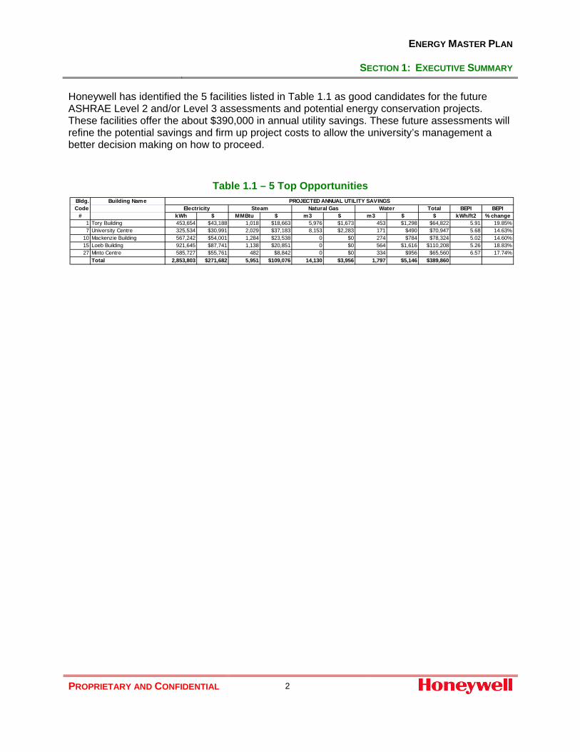
Honeywell has identified the 5 facilities listed in Table 1.1 as good candidates for the future ASHRAE Level 2 and/or Level 3 assessments and potential energy conservation projects. These facilities offer the about $390,000 in annual utility savings. These future assessments will refine the potential savings and firm up project costs to allow the university’s management a better decision making on how to proceed.
Table 1.1 – 5 Top Opportunities
Bldg. Building NameCode Total BEPI BEPI
# kWh $ MMBtu $ m3 $ m3 $ $ kWh/ft2 % change1 Tory Building 453,654 $43,188 1,018 $18,663 5,976 $1,673 453 $1,298 $64,822 5.91 19.85%7 University Centre 325,534 $30,991 2,029 $37,183 8,153 $2,283 171 $490 $70,947 5.68 14.63%
10 Mackenzie Building 567,242 $54,001 1,284 $23,538 0 $0 274 $784 $78,324 5.02 14.60%15 Loeb Building 921,645 $87,741 1,138 $20,851 0 $0 564 $1,616 $110,208 5.26 18.83%27 Minto Centre 585,727 $55,761 482 $8,842 0 $0 334 $956 $65,560 6.57 17.74%
Total 2,853,803 $271,682 5,951 $109,076 14,130 $3,956 1,797 $5,146 $389,860
PROJECTED ANNUAL UTILITY SAVINGSSteam Natural Gas WaterElectricity

ENERGY MASTER PLAN
SECTION 2: UTILITY ANALYSIS
PROPRIETARY AND CONFIDENTIAL 3
2.0 Utility Analysis Honeywell has compiled, reviewed and analyzed the campus available utility bills for the period of January 2009 to December 2012. In addition, the sub-metered utilities for individual buildings were also reviewed and analyzed for calendar years 2009 and 2012.
The results of this analysis are presented in this report. Utility billing summaries along with copies of the utility bills are included in on a CD attached to the back cover of this report.
2.1 Utility Map Table 2.1 lists the utility accounts that have been analyzed for this report.
Table 2.1 - List of Utility Accounts
Service or Bldg. Name Utility Utility Type Account No.
Main Electricity Hydro Ottawa Electricity 94028530003881956000
CHP Gas Enbridge Natural Gas 855101009990
Tory Building (#1) Enbridge Natural Gas 865287669992
Commons (#19) Enbridge Natural Gas 865587739991
Leeds (#30) Enbridge Natural Gas 865114569996
Ice House (#39) Enbridge Natural Gas 865621679994
Tennis Centre (#40) Enbridge Natural Gas 8658906779990
Canal Building (#42) Enbridge Natural Gas 910004965533
Lennox & Addington (#44) Enbridge Natural Gas 910008756332
Consolidated Gas Enbridge Natural Gas 000000655320
Water Ottawa Water 0055-2520-10
Water Ottawa Water 0055-2522-10
Water Ottawa Water 0055-2523-10
Water Ottawa Water 1007-2620-01
Consolidated Gas account summarizes the natural gas consumption in several buildings listed in Table 2.2

ENERGY MASTER PLAN
SECTION 2: UTILITY ANALYSIS
PROPRIETARY AND CONFIDENTIAL 4
Table 2.2 - Consolidated Gas Account
Building Name Supplementary Account #
University Centre (#7) 026501006516
Physical Recreation Centre (#9) 026509653514
Mackenzie Building (#10) 026509654303
Maintenance Building (#11) 026501037214
Maintenance Building Shed (#11) 026501533113
Steacie Building (#12) 026509653902
Loeb Building (#15) 026501801022
Architecture (#22) 026501117313
St. Patrick ‘s Building (#23) 026501014413
Social Sciences Research (#24) 026501016812
Day Care (#28) 026501015921
Prescott House (#34) 026501032110
Field House (#35) 026501031716
Frontenac House (#41) 026550256015
2.2 Utility Analysis
Electricity
A single electric meter measures the main feed electricity consumption for the entire university campus, which is further sub-metered at each building level.
The historic trend of campus energy and peak demand in Figure 2.1 shows a large base load: energy = 5,200,000 kWh/month and peak monthly demand = 9,500 kW and a characteristic summer cooling component.

ENERGY MASTER PLAN
SECTION 2: UTILITY ANALYSIS
PROPRIETARY AND CONFIDENTIAL 5
Figure 2.1 - Electric Energy Consumption
Natural Gas Several meters measure natural gas consumption on campus. For the purpose of this report the campus gas consumption has been grouped into 2 categories:
1. Central Heating Plant (CHP) gas – natural gas consumed in the CHP, which supplies steam to the vast majority of buildings on campus. This is the largest gas account in terms of volume. The historic trend of campus CHP gas use in Figure 2.2 shows a base load of about 260,000 m3 and a characteristic winter heating component.
2. Other gas – natural gas consumed in the individual buildings (refer to Tables 2.1 and 2.2
in Section 2.1 Utility Map). The historic trend of campus other gas use in Figure 2.3 shows for years 2009-2011 a base load of about 25,000 m3 and a characteristic winter heating component. Only a partial consumption data was available for 2012, hence the trend displays abnormal consumption profile. For more details refer to Utility Data Management in Appendix A.
‐
2,000
4,000
6,000
8,000
10,000
12,000
14,000
16,000
‐
1,000,000
2,000,000
3,000,000
4,000,000
5,000,000
6,000,000
7,000,000
8,000,000
2/1/20
09
4/1/20
09
6/1/20
09
8/1/20
09
10/1/200
9
12/1/200
9
2/1/20
10
4/1/20
10
6/1/20
10
8/1/20
10
10/1/201
0
12/1/201
0
2/1/20
11
4/1/20
11
6/1/20
11
8/1/20
11
10/1/201
1
12/1/201
1
2/1/20
12
4/1/20
12
6/1/20
12
8/1/20
12
10/1/201
2
12/1/201
2
Peak dem
and ‐k
W
Electric en
ergy ‐kW
h
Date
Campus Electric Energy and Peak DemandJan 2009 ‐ Dec 2012
Demand (kW) Energy (kWh)

ENERGY MASTER PLAN
SECTION 2: UTILITY ANALYSIS
PROPRIETARY AND CONFIDENTIAL 6
Figure 2.2 - CHP Natural Gas Consumption
Figure 2.3 - Other Natural Gas Consumption
‐
200,000
400,000
600,000
800,000
1,000,000
1,200,000
1,400,000
1,600,000
1,800,000
2,000,000
1/21
/200
9
3/21
/200
9
5/21
/200
9
7/21
/200
9
9/21
/200
9
11/21/20
09
1/21
/201
0
3/21
/201
0
5/21
/201
0
7/21
/201
0
9/21
/201
0
11/21/20
10
1/21
/201
1
3/21
/201
1
5/21
/201
1
7/21
/201
1
9/21
/201
1
11/21/20
11
1/21
/201
2
3/21
/201
2
5/21
/201
2
7/21
/201
2
9/21
/201
2
11/21/20
12
Natural gas ‐m3
Date
Campus CHP ‐ Natural Gas ConsumptionJan 2009 ‐ Dec 2012
‐
50,000
100,000
150,000
200,000
250,000
300,000
Jan 20
09
Mar 200
9
May 200
9
Jul 200
9
Sep 20
09
Nov 20
09
Jan 20
10
Mar 201
0
May 201
0
Jul 201
0
Sep 20
10
Nov 20
10
Jan 20
11
Mar 201
1
May 201
1
Jul 201
1
Sep 20
11
Nov 20
11
Jan 20
12
Mar 201
2
May 201
2
Jul 201
2
Sep 20
12
Nov 20
12
Natural gas ‐m3
Date
Campus Other Natural Gas ConsumptionJan 2009 ‐ Dec 2012

ENERGY MASTER PLAN
SECTION 2: UTILITY ANALYSIS
PROPRIETARY AND CONFIDENTIAL 7
Water Four water meters measure total consumption on campus. For the purpose of this report the data have been combined to reflect entire campus usage. The historic trend of campus water use in Figure 2.4 shows a relatively constant consumption of about 35,000 m3/month up to May 2010 and again from March to December 2012. In the period between these dates the campus water consumption pattern was skewed by a series of meter reading errors. For more details refer to Utility Data Management in Appendix A.
Figure 2.4 - Water Consumption
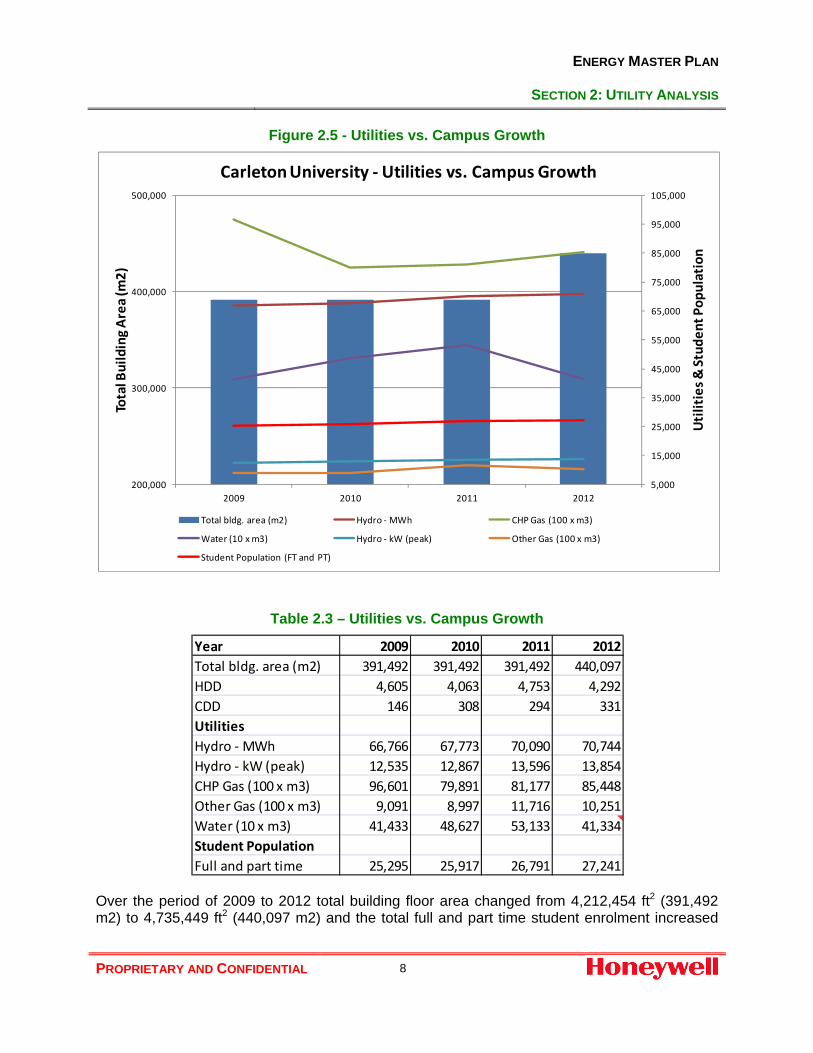
2.3 Utilities vs. Campus Growth Figure 2.5 overlays the annual total energy and water consumption over the total campus building floor area. This figure also includes the total student enrolment data. Units of measurements have been purposely modified to show all energy and water consumptions profiles over the campus growth in a single figure. Data source for this figure is summarized in Table 2.3.
(40,000)
(20,000)
‐
20,000
40,000
60,000
80,000
100,000
120,000
140,000
160,000
180,000
Jan 20
09Feb 20
09Mar 200
9Ap
r 200
9May 200
9Jun 20
09Jul 200
9Au
g 200
9Sep 20
09Oct 200
9No
v 20
09De
c 200
9Jan 20
10Feb 20
10Mar 201
0Ap
r 201
0May 201
0Jun 20
10Jul 201
0Au
g 201
0Sep 20
10Oct 201
0No
v 20
10De
c 201
0Jan 20
11Feb 20
11Mar 201
1Ap
r 201
1May 201
1Jun 20
11Jul 201
1Au
g 201
1Sep 20
11Oct 201
1No
v 20
11De
c 201
1Jan 20
12Feb 20
12Mar 201
2Ap
r 201
2May 201
2Jun 20
12Jul 201
2Au
g 201
2Sep 20
12Oct 201
2No
v 20
12De
c 201
2
Water ‐m3
Date
Campus Water ConsumptionJan 2009 ‐ Dec 2012
ENERGY MASTER PLAN
SECTION 2: UTILITY ANALYSIS
PROPRIETARY AND CONFIDENTIAL 8
Figure 2.5 - Utilities vs. Campus Growth
Table 2.3 – Utilities vs. Campus Growth
Over the period of 2009 to 2012 total building floor area changed from 4,212,454 ft2 (391,492 m2) to 4,735,449 ft2 (440,097 m2) and the total full and part time student enrolment increased
5,000
15,000
25,000
35,000
45,000
55,000
65,000
75,000
85,000
95,000
105,000
200,000
300,000
400,000
500,000
2009 2010 2011 2012
Utilities &
Stude
nt Pop
ulation
Total Building Area (m
2)
Carleton University ‐Utilities vs. Campus Growth
Total bldg. area (m2) Hydro ‐MWh CHP Gas (100 x m3)
Water (10 x m3) Hydro ‐ kW (peak) Other Gas (100 x m3)
Student Population (FT and PT)
Year 2009 2010 2011 2012Total bldg. area (m2) 391,492 391,492 391,492 440,097HDD 4,605 4,063 4,753 4,292CDD 146 308 294 331UtilitiesHydro ‐ MWh 66,766 67,773 70,090 70,744Hydro ‐ kW (peak) 12,535 12,867 13,596 13,854CHP Gas (100 x m3) 96,601 79,891 81,177 85,448Other Gas (100 x m3) 9,091 8,997 11,716 10,251Water (10 x m3) 41,433 48,627 53,133 41,334Student PopulationFull and part time 25,295 25,917 26,791 27,241

ENERGY MASTER PLAN
SECTION 2: UTILITY ANALYSIS
PROPRIETARY AND CONFIDENTIAL 9
from 25,295 to 27,241. In this comparison, the weather sensitive factors affecting electricity and gas consumption patterns are somewhat muted except for the sharp drop of CHP gas from 2009 to 2010 due to warmer winter in 2010. Upward trend in energy and water consumption is easily visible due to the internal load growth, increase in student enrolment and the addition of new buildings on campus. Water and other gas consumption appear defy this trend in 2012, but this may be due to the fact that this analysis is based incomplete billing data for these utilities during this period.
2.4 Energy and Water Sub-metering Majority of buildings on campus are equipped with the following types of sub-meters:
• Electricity – measure individual building energy consumption in kWh • Steam – measure individual building steam or medium temperature hot water (MTHW)
consumption in klbs (of steam) • Natural gas – measure individual building gas consumption in m3 (these are Enbridge
gas meters, see Utility Map Tables 2.1 and 2.2) • Water – measure individual building water consumption in m3
Sub-metered energy and water use data for individual buildings for 2009 and 2012 calendar years are summarized in Tables 2.4 and 2.5, respectively. The following deviations in energy and water use between the actual utility bills and the sub-meters have been noted: Electric sub-meters: Campus total billed electricity consumption was 10.2% and 11.6% higher in 2009 and 2012 than the total of the individual buildings electrical sub-meters for these years. The following non metered electrical loads may account for these deviations:
• Campus street and parking area lights • Tunnel lights • Sport fields lights • Grounds Building (#45) • Bronson Sub-station (#72) • Accuracy of building electric sub-meters
Steam/MTHW sub-meters (CHP gas): Individual building sub-meters measure thermal energy consumption expressed in klbs (1000 pounds) of steam. Conversion of natural gas input to CHP to the steam output was necessary to facilitate an easy comparison. For the purpose of this analysis the following assumptions and conversion factors have been utilized:
• CHP seasonal plant efficiency = 70% • Steam consumed within CHP = 15% of total steam output • 1 m3 of natural gas = 0.03584 MMBtu

ENERGY MASTER PLAN
SECTION 2: UTILITY ANALYSIS
PROPRIETARY AND CONFIDENTIAL 10
• 1 klbs of steam = 1 MMBtu Total steam/MTHW use in the individual buildings correlated very well to the total billed natural gas consumption at CHP with - 0.1% and 2.5% deviations in 2009 and 2012, respectively. Other Gas: Campus total billed “Other gas” consumption was 18.4% and 6.8% lower in 2009 and 2012 than the total of individual buildings gas sub-meters for these years. These deviations may be accounted for by the billing estimates and subsequent corrections by Enbridge. For more details refer to Utility Data Management in Appendix A. Water: Campus total billed water consumption was 7.2% and 7.0% lower in 2009 and 2012 than the total of individual buildings water sub-meters for these years. This deviation may be accounted for by the accuracy of water sub-meters. For more details refer to Utility Data Management in Appendix A.

ENERGY MASTER PLAN
SECTION 2: UTILITY ANALYSIS
PROPRIETARY AND CONFIDENTIAL 11
Table 2.4 – 2009 Building Energy and Water Use – Sub-meters
Bldg. Building Name
Code Electricity Steam - MTHW Natural Gas Water
# kWh MMBtu m3 m3
1 Tory Building 2,141,450 3,069 20,803 27,414
2 MacOdrum Library 4,085,033 6,785 0 15,085
3 Paterson Hall 1,047,456 10,257 0 4,478
4 Southam Hall 1,468,491 6,875 0 5,324
5 Renfrew House 247,716 2,774 0 3,596
6 Lanark House 213,032 3,042 0 5,235
7 University Centre 3,321,228 8,073 71,175 28,406
8 Gymnasium 578,196 0 210,392 2,776
9 Physical Rec Centre 1,803,356 11,103 13,655 21,107
10 Mackenzie Building 4,520,439 13,307 66 31,763
11 Maintenance Building 1,117,560 3,881 3,019 2,580
12 Steacie Building 3,317,104 24,546 384 16,443
13 Herzberg Laboratories 3,133,139 8,136 0 9,121
14 Russell/Grenville House 562,955 9,606 0 23,347
15 Loeb Building 3,229,891 8,722 10,383 9,205
16 HHJ Nesbitt Biology 1,079,573 11,578 0 18,100
17 Robertson Hall 1,887,744 4,216 0 7,831
18 Glengarry House 1,495,861 7,041 0 22,232
19 Residence Commons 1,856,258 12,262 75,757 21,856
21 Dunton Tow er 1,643,380 4,276 0 16,707
22 Architecture 776,703 5,915 5,830 5,645
23 St. Patrick's Building 1,077,700 1,994 48,057 2,400
24 Social Sciences Research 145,563 0 18,250 1,500
25 Life Sciences Research 1,184,022 5,761 0 5,000
26 Stormont-Dundas 1,123,563 5,214 0 20,479
27 Minto Centre 3,601,736 8,913 0 15,538
28 Colonel By Child Care 75,147 0 11,240 657
29 Carleton Technology 1,481,882 3,777 0 6,814
30 Leeds House 1,272,607 0 135,063 22,742
31 Azrieli Theatre 520,943 1,108 0 9,670
32 Azrieli Pavilion 1,036,309 1,557 0 12,673
33 National Wildlife Research Centre 2,226,052 3,079 0 1,168
34 Prescott House 1,243,890 4,324 7,757 13,773
35 Fieldhouse 90,875 0 13,011 384
36 Alumni Hall 1,115,376 1,892 0 1,009
37/38 Human Computer Int. & Visual 1,588,677 2,090 0 13,542
39 Ice House 2,312,785 0 296,135 12,910
40 Tennis Centre 258,325 0 168,951 1,500
41 Frontenac House 718,098 1,122 4,345 6,464
2009 Total 60,600,115 206,295 1,114,273 446,474
Actual consumption from 2009 bills 66,765,583 206,000 909,062 414,331
% deviation Actual vs. Submetered 10.2% -0.1% -18.4% -7.2%
EXISTING USAGE

ENERGY MASTER PLAN
SECTION 2: UTILITY ANALYSIS
PROPRIETARY AND CONFIDENTIAL 12
Table 2.5 – 2012 Building Energy and Water Use – Sub-meters
Bldg. Building Name
Code Electricity Steam - MTHW Natural Gas Water
# kWh MMBtu m3 m3
1 Tory Building 2,753,123 3,613 28,757 25,854
2 MacOdrum Library 2,750,652 5,846 0 22,943
7 University Centre 3,281,840 6,208 168,723 21,846
10 Mackenzie Building 3,762,182 9,221 39 16,437
11 Maintenance Building 1,925,540 526 5,031 2,126
12 Steacie Building 2,989,160 19,148 259 18,389
13 Herzberg Laboratories 2,910,217 6,708 0 4,259
15 Loeb Building 3,720,466 9,749 8,237 16,524
16 HHJ Nesbitt Biology 732,153 8,683 0 9,640
21 Dunton Tow er 1,882,556 3,804 0 12,834
22 Architecture 565,793 1,617 6,695 2,453
23 St. Patrick's Building 1,607,684 2,517 66,099 3,963
27 Minto Centre 3,646,516 1,543 0 8,229
29 Carleton Technology 1,323,426 3,231 0 8,308
31 Azrieli Theatre 419,737 584 0 10
32 Azrieli Pavilion 900,469 559 0 587
37/38 Human Computer Int. & Visual 1,825,421 2,124 0 1,528
3 Paterson Hall 672,855 6,528 0 2,567
4 Southam Hall 1,275,616 5,162 0 5,817
5 Renfrew House 255,607 2,524 0 6,344
6 Lanark House 208,350 1,649 0 6,021
8 Gymnasium 251,157 0 64,993 3,712
9 Physical Rec Centre 1,572,976 8,380 14,797 29,258
14 Russell/Grenville House 537,152 4,390 0 7,744
17 Robertson Hall 2,927,808 4,153 0 13,056
18 Glengarry House 1,609,802 8,032 0 30,821
19 Residence Commons 1,372,519 16,383 99,337 22,751
24 Social Sciences Research 141,927 0 24,273 10,658
25 Life Sciences Research 1,169,991 4,602 0 14,438
26 Stormont-Dundas 960,943 3,941 0 35,091
28 Colonel By Child Care 72,710 0 14,964 855
30 Leeds House 1,283,503 0 162,773 27,167
33 National Wildlife Research Centre 2,492,752 3,497 0 1,120
34 Prescott House 1,208,162 3,024 8,339 12,865
35 Fieldhouse 268,833 0 30,635 540
36 Alumni Hall 811,009 1,229 0 961
39 Ice House 2,810,525 0 194,978 14,098
40 Tennis Centre 299,166 0 195,162 0
41 Frontenac House 667,700 2,633 1,765 6,407
42 Canal Building 1,779,784 9,367 0 1,020
43 River Building 776,977 1,668 0 851
44 New Residence 969,300 5,099 4,139 14,527
2012 Total 63,394,055 177,941 1,099,995 444,621
Actual consumption from 2012 bills 70,744,261 182,217 1,025,132 413,336
% deviation Actual vs. Submetered 11.6% 2.4% -6.8% -7.0%
EXISTING USAGE
ENERGY MASTER PLAN
SECTION 2: UTILITY ANALYSIS
PROPRIETARY AND CONFIDENTIAL 13
2.5 Utility Data Management Over the years the University has made a great progress toward monitoring, collecting and managing energy and water operating data for the entire campus and the individual buildings. Virtually all buildings on campus are now equipped with energy (electricity, steam, natural gas) and water sub-meters. The captured data from both the building sub-meters (electricity, steam, water) and individual building gas bills for a each budget year is entered and maintained in the spreadsheets (Excel format) for both “Ancillary” and “Non-Ancillary” facilities. This information has been used for the university energy budget forecasting and internal accounting and utilities cost recovery from various tenants and/or departments. Honeywell used the data from these spreadsheets for the building energy and water use summaries shown in Tables 2.4 and 2.5 in Section 2.4 and building energy performance benchmarks shown in Table 3.2 in Section 3.3. Capturing the building operating data is the first step toward improved management of the campus facilities. Analysis of this data and follow up actions constitute the second and third steps in driving operational excellence. Observations of areas where corrective actions are recommended, are outlined in Appendix A.

ENERGY MASTER PLAN
SECTION 3: CAMPUS MASTER PLAN & FUTURE ENERGY REQUIREMENTS
PROPRIETARY AND CONFIDENTIAL 14
3.0 Campus Master Plan & Future Energy Requirements
3.1 Overview Energy Master Plan can be viewed as a supplement to the two already published documents:
• Defining Dreams – A Strategic Plan for Carleton University 2009 • Carleton University – Campus Master Plan 2010
Strategic Plan provides a vision and sets goals for research and academic teaching excellence and enhancing student life. Campus Master Plan describes the future physical development of the campus to satisfy the goals set in the Strategic Plan. Energy Master Plan on the other hand looks at the campus historical energy and water use and the potential future requirements for these utilities to satisfy the campus physical development set in the Campus Master Plan.
3.2 Campus Master Plan Campus Master Plan by du Toit Allsopp Hillier in January 2010 describes the future physical development of the campus. It deals with the location and the size of buildings and their general use. This document does not provide any time frame for the campus development buildup as it is expected that this will vary over time due to availability of funding.
Figure 3.1 shows the existing building stock and future development under the Campus Master Plan. Table 3.1 provides the summary of new building massing statistics arranged by building type. Figure 3.2 shows the campus key map for the new buildings statistics.
The current plan calls for construction of new facilities with the total floor area of 4,472,898 ft2 (or 415,532 m2). Under this plan 490,172 ft2 (45,537 m2) of existing building stock will be removed. In the end, the campus will grow from the current 4,737,324 ft2 (440,097 m2) to 8,720,050 ft2 (810,093 m2).

ENERGY MASTER PLAN
SECTION 3: CAMPUS MASTER PLAN & FUTURE ENERGY REQUIREMENTS
PROPRIETARY AND CONFIDENTIAL 15
Figure 3.1 – Carleton University Campus Master Site Plan
Legend:
Existing Building
Vertical Expansion
New Building

ENERGY MASTER PLAN
SECTION 3: CAMPUS MASTER PLAN & FUTURE ENERGY REQUIREMENTS
PROPRIETARY AND CONFIDENTIAL 16
Table 3.1 – Summary of Building Massing Statistics
Tag Building Name Area (ft2) TypeI1 Dunton Tower Infill 55,574 AcademicI2 Library Infill 31,571 AcademicI4 McKenzie Infill 21,775 AcademicC1 Paterson Replacement 292,466 AcademicC2 L.S.R. Replacement 139,791 AcademicC4 S.S.R. Replacement 122,289 AcademicC7 Library Road 91,084 Academic/AdminV1 Library Expansion 45,316 AcademicV2 Herzberg Annex 11,539 Academic
Academic Total 811,405C10 Old Gym + Daycare 141,492 AthleticsM1 Tennis Replacement 104,528 AthleticsM2 Bronson Frontage 325,436 Athletics
Athletics Total 571,456N1 North Campus 59,158 ResearchN2 North Campus 61,268 ResearchN3 North Campus 60,407 ResearchN4 North Campus 60,364 ResearchN5 North Campus 71,903 ResearchN6 North Campus 118,920 ResearchN7 North Campus 114,700 ResearchN8 North Campus 55,025 ResearchN9 North Campus 55,886 ResearchN10 North Campus 54,250 ResearchN11 North Campus 104,022 Research
Research Total 815,903R1 Residence 172,955 ResidenceR2 Residence Commons Addition 37,867 ResidenceR3 Residence 117,736 ResidenceR4 Residence 117,736 ResidenceR5 Residence 117,736 ResidenceR6 Residence 117,736 ResidenceR7 Residence 117,736 ResidenceR8 Residence + Commons 264,921 Residence
Residence Total 1,064,423C12 Maintenance Replacement 53,281 AncillaryC13 Maintenance Replacement 71,881 AncillaryC14 Garage Replacement 110,502 AncillaryM3 New Maintenance 88,835 Ancillary
Services Total 324,499I3 UniCentre Expansion 11,883 Student CentreC8 Over Rail 231,618 Student CentreC15 Alumni Park Back 49,557 Student Centre
Student Centre Total 293,058C3 Parking Lot 1 94,959 ParkingC5 Parking Lot 2 N. 131,470 ParkingC6 Parking Lot 2 S. 104,259 ParkingC9 Parking Lot 4 133,139 ParkingC11 Parking Lot 11 128,327 Parking
Parking Total 592,154Grand Total 4,472,898
Bldg. # Building Name Area (ft2) Type3 Paterson Hall 79,989 Academic8 Gymnasium 28,159 Athletics11 Maintenance 43,832 Ancillary24 Social Sciences Research Bldg. 14,370 Academic25 Life Sciences Research Bldg. 25,296 Academic28 Colonel By Child Care Centre 5,662 Ancillary40 Tennis Centre 36,006 AthleticsPG Parking Garage 256,857 Ancillary
Total to be removed 490,172
Buildings to be removed
New Buildings

ENERGY MASTER PLAN
SECTION 3: CAMPUS MASTER PLAN & FUTURE ENERGY REQUIREMENTS
PROPRIETARY AND CONFIDENTIAL 17
Figure 3.2 – Key Map for New Buildings Statistics
Legend:
C – Core Area M – Mid Campus
I – Infill N – North Campus
V – Vertical Expansion R – Residential Campus
ENERGY MASTER PLAN
SECTION 3: CAMPUS MASTER PLAN & FUTURE ENERGY REQUIREMENTS
PROPRIETARY AND CONFIDENTIAL 18
3.3 Campus Energy Benchmarks In simplistic terms, energy benchmarking can be defined as the process of comparing energy performance of a sample building to a similar facility or group of facilities. This process can be used for developing energy management plans where the performance of the existing facilities is compared to that of the best practice standard. In addition, the benchmarking can be used to as a forecasting tool to predict the future energy and water use of new facilities based on the past performance of existing facilities of similar type and operation.
For the purpose of this analysis we have used the principles of energy benchmarking to predict the future energy and water requirements for new facilities developed under the 2010 Campus Master Plan.
Table 3.2 provides the summary of energy and water consumption benchmarks for campus existing building stock arranged by building type based on 2012 data.
Average, maximum and minimum performance benchmarks were also calculated for the following building types:
• Academic
• Research
• Athletics
• Ancillary
• Residences

ENERGY MASTER PLAN
SECTION 3: CAMPUS MASTER PLAN & FUTURE ENERGY REQUIREMENTS
PROPRIETARY AND CONFIDENTIAL 19
Table 3.2 - Energy Performance Benchmarks - Existing Building Stock
Bldg. Building Name Building Area Code Type ft2 TOTAL BEPI
# kWh kW kWh/ft2 W/ft2 MMBtu ekWh/ft2 m3 ekWh/ft2 ekWh/ft2 m3 l/ft2
2 MacOdrum Library Academic 204,177 2,750,652 601 13.47 2.94 5,846 8.39 0 0.00 21.86 22,943 11210 Mackenzie Building Academic 188,095 3,762,182 822 20.00 4.37 9,221 14.37 39 0.00 34.37 16,437 8715 Loeb Building Academic 238,375 3,720,466 813 15.61 3.41 9,749 11.99 8,237 0.36 27.96 16,524 6916 HHJ Nesbitt Biology Academic 68,030 732,153 160 10.76 2.35 8,683 37.41 0 0.00 48.17 9,640 14221 Dunton Tow er Academic 184,876 1,882,556 411 10.18 2.23 3,804 6.03 0 0.00 16.21 12,834 6922 Architecture Academic 92,723 565,793 124 6.10 1.33 1,617 5.11 6,695 0.76 11.97 2,453 2623 St. Patrick's Building Academic 75,490 1,607,684 351 21.30 4.65 2,517 9.77 66,099 9.19 40.26 3,963 5227 Minto Centre Academic 110,624 3,646,516 797 32.96 7.20 1,543 4.09 0 0.00 37.05 8,229 7431 Azrieli Theatre Academic 37,783 419,737 92 11.11 2.43 584 4.53 0 0.00 15.64 10 032 Azrieli Pavilion Academic 49,516 900,469 197 18.19 3.97 559 3.31 0 0.00 21.50 587 12
37/38 Human Computer Int. & Visual Academic 97,309 1,825,421 399 18.76 4.10 2,124 6.40 0 0.00 25.16 1,528 163 Paterson Hall Academic 79,989 672,855 147 8.41 1.84 6,528 23.92 0 0.00 32.33 2,567 324 Southam Hall Academic 99,526 1,275,616 279 12.82 2.80 5,162 15.20 0 0.00 28.02 5,817 58
42 Canal Building Academic 96,609 1,779,784 389 18.42 4.03 9,367 28.42 0 0.00 46.84 1,020 1143 River Building Academic 181,593 776,977 170 4.28 0.94 1,668 2.69 0 0.00 6.97 851 51 Tory Building Academic / Admin 138,110 2,753,123 602 19.93 4.36 3,613 7.67 28,757 2.19 29.79 25,854 187
Academic Total Average 15.14 3.31 11.83 0.78 27.76 60Maximum 32.96 7.20 37.41 9.19 48.17 187Minimum 4.28 0.94 2.69 0.00 6.97 0
12 Steacie Building Research 107,104 2,989,160 653 27.91 6.10 19,148 52.40 259 0.03 80.33 18,389 17213 Herzberg Laboratories Research 152,562 2,910,217 636 19.08 4.17 6,708 12.89 0 0.00 31.96 4,259 2824 Social Sciences Research Research 14,370 141,927 31 9.88 2.16 0 0.00 24,273 17.74 27.61 10,658 74225 Life Sciences Research Research 25,296 1,169,991 256 46.25 10.11 4,602 53.32 0 0.00 99.57 14,438 571
Research Total Average 25.78 5.63 29.65 4.44 59.87 378Maximum 46.25 10.11 53.32 17.74 99.57 742Minimum 9.88 2.16 0.00 0.00 27.61 28
8 Gymnasium Athletics 28,159 251,157 55 8.92 1.95 0 0.00 64,993 24.23 33.15 3,712 1329 Physical Rec Centre Athletics 125,199 1,572,976 344 12.56 2.75 8,380 19.62 14,797 1.24 33.42 29,258 234
35 Fieldhouse Athletics 47,998 268,833 59 5.60 1.22 0 0.00 30,635 6.70 12.30 540 1136 Alumni Hall Athletics 37,503 811,009 177 21.63 4.73 1,229 9.61 0 0.00 31.23 961 2639 Ice House Athletics 99,914 2,810,525 614 28.13 6.15 0 0.00 194,978 20.49 48.62 14,098 14140 Tennis Centre Athletics 36,006 299,166 65 8.31 1.82 0 0.00 195,162 56.91 65.22 0 0
Athletics Total Average 14.19 3.10 4.87 18.26 37.33 91Maximum 28.13 6.15 19.62 56.91 65.22 234Minimum 5.60 1.22 0.00 0.00 12.30 0
EXISTING USAGE Electricity Steam - MTHW Natural Gas Water

ENERGY MASTER PLAN
SECTION 3: CAMPUS MASTER PLAN & FUTURE ENERGY REQUIREMENTS
PROPRIETARY AND CONFIDENTIAL 20
Table 3.2 - Energy Performance Benchmarks - Existing Building Stock – cont’d
Bldg. Building Name Building Area Code Type ft2 TOTAL BEPI
# kWh kW kWh/ft2 W/ft2 MMBtu ekWh/ft2 m3 ekWh/ft2 ekWh/ft2 m3 l/ft2
7 University Centre Ancillary / Academic/ Admin 177,183 3,281,840 717 18.52 4.05 6,208 10.27 168,723 10.00 38.79 21,846 12317 Robertson Hall Administrative 93,208 2,927,808 640 31.41 6.86 4,153 13.06 0 0.00 44.47 13,056 14011 Maintenance Building Ancillary 43,832 1,925,540 421 43.93 9.60 526 3.51 5,031 1.21 48.65 2,126 4929 Carleton Technology Ancillary 68,515 1,323,426 289 19.32 4.22 3,231 13.82 0 0.00 33.14 8,308 12119 Residence Commons Ancillary 185,323 1,372,519 300 7.41 1.62 16,383 25.91 99,337 5.63 38.94 22,751 12328 Colonel By Child Care Ancillary 5,662 72,710 16 12.84 2.81 0 0.00 14,964 27.75 40.59 855 15133 National Wildlife Research Centre Ancillary / Academic 60,000 2,492,752 545 41.55 9.08 3,497 17.08 0 0.00 58.63 1,120 19
Ancillary Total Average 25.00 5.46 11.95 6.37 43.32 104Maximum 43.93 9.60 25.91 27.75 58.63 151Minimum 7.41 1.62 0.00 0.00 33.14 19
5 Renfrew House Residence 52,680 255,607 56 4.85 1.06 2,524 14.04 0 0.00 18.89 6,344 1206 Lanark House Residence 51,469 208,350 46 4.05 0.88 1,649 9.39 0 0.00 13.44 6,021 117
14 Russell/Grenville House Residence 95,953 537,152 117 5.60 1.22 4,390 13.41 0 0.00 19.01 7,744 8118 Glengarry House Residence 154,715 1,609,802 352 10.40 2.27 8,032 15.22 0 0.00 25.62 30,821 19926 Stormont-Dundas Residence 118,192 960,943 210 8.13 1.78 3,941 9.77 0 0.00 17.90 35,091 29730 Leeds House Residence 169,139 1,283,503 280 7.59 1.66 0 0.00 162,773 10.10 17.69 27,167 16134 Prescott House Residence 135,005 1,208,162 264 8.95 1.96 3,024 6.57 8,339 0.65 16.16 12,865 9541 Frontenac House Residence 87,998 667,700 146 7.59 1.66 2,633 8.77 1,765 0.21 16.57 6,407 7344 New Residence Residence 170,000 969,300 212 5.70 1.25 5,099 8.79 4,139 0.26 14.75 14,527 85
Residence Total Average 6.98 1.53 9.55 1.25 17.78 136Maximum 10.40 2.27 15.22 10.10 25.62 297Minimum 4.05 0.88 0.00 0.00 13.44 73
EXISTING USAGE Electricity Steam - MTHW Natural Gas Water

ENERGY MASTER PLAN
SECTION 3: CAMPUS MASTER PLAN & FUTURE ENERGY REQUIREMENTS
PROPRIETARY AND CONFIDENTIAL 21
3.4 Future Energy and Water Requirements A number of existing buildings will be demolished to give way for the new construction. Table 3.3 provides the summary of buildings planned for demolition along with 2012 energy and water consumption data. Removed utilities will free up some capacity on the existing campus energy and water infrastructure systems.
Table 3.3 – Buildings Planned for Removal under 2010 Campus Master Plan
Average energy and water consumption benchmarks for each building type have been used as the starting point for predicting the future energy and water requirements for the new buildings. Given the University management ongoing commitment to energy efficiency and environmental responsibility this analysis assumes that all new buildings will be constructed to the improved construction standards, utilizing high performance building materials, sustainable energy sources and high efficiency building technologies and equipment.
Table 3.4 shows the estimated energy and water reduction factors, which have been used for this analysis. It should be noted that these factors may further improve in the future due to ongoing advances in the development of high performance building materials and energy efficient equipment and building technologies. On another hand, the more conservative factors can be used, should the construction budget constraints dictate the use of the standard and/or less effective building materials, equipment and technologies.
Table 3.4 – Energy and Water Reduction Factors
CHP Gas Other Gas Total Gas WaterBldg. # Building Name Area (ft2) Type kW MWh MMBtu MMBtu MMBtu m3
3 Paterson Hall 79,989 Academic 147 673 9,326 0 9,326 2,5678 Gymnasium 28,159 Athletics 55 251 0 2,329 2,329 3,71211 Maintenance 43,832 Ancillary 421 1,926 751 180 931 2,12624 Social Sciences Research Bldg. 14,370 Academic 31 142 0 870 870 10,65825 Life Sciences Research Bldg. 25,296 Academic 256 1,170 6,574 0 6,574 14,43828 Colonel By Child Care Centre 5,662 Ancillary 16 73 0 536 536 85540 Tennis Centre 36,006 Athletics 65 299 0 6,995 6,995 0PG Parking Garage 256,857 Ancillary 358 266 0 0
Total to be removed 490,172 1,348 4,800 16,650 10,911 27,561 34,356
Electricity
Building type Electricity Thermal WaterAcademic 30% 40% 50%Research 30% 40% 50%Athletics 30% 40% 50%Ancillary 30% 40% 50%Residences 30% 40% 50%Parking 50%

ENERGY MASTER PLAN
SECTION 3: CAMPUS MASTER PLAN & FUTURE ENERGY REQUIREMENTS
PROPRIETARY AND CONFIDENTIAL 22
Table 3.5 provides the summary of the estimated annual energy and water consumption for the new buildings based on improved construction standards and energy performance.
Table 3.5 – Projected Energy and Water Consumption in New Buildings
Table 3.6 provides the summary of the estimated annual energy and water consumption for the new and enlarged Carleton University campus.
Table 3.6 – Projected Energy and Water Consumption for New Campus
Table 3.7 provides the projected perspectives on the future Carleton University campus once the entire scope of 2010 Master Plan development and the impact of the campus growth on the overall energy and water consumption. Once the Master Plan is implemented the total campus building floor area will grow by 84% from 2012 level. The new campus annual electricity, fuel and water consumption are expected to increase by 57%, 55% and 66%, respectively.
Table 3.7 – New Campus Statistics
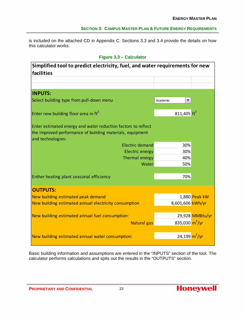
3.5 Calculator for Future Utility Requirements Honeywell has developed a calculating tool to perform simple and quick calculations to predict the future energy and water use requirements for different building types (Figure 3.3). This tool
Fuel WaterBuilding type Area (ft2) Peak kW MWh MMBtu m3Academic 811,405 1,880 8,602 29,928 24,199Research 815,903 3,217 14,723 81,345 154,210Athletics 571,456 1,241 5,677 38,663 25,882Ancillary 617,557 2,361 10,806 33,086 32,006Residences 1,064,423 1,137 5,204 33,610 72,641Parking 592,154 412 307Total 4,472,898 10,249 45,318 216,632 308,938
Electricity
Fuel WaterArea (ft2) Peak kW MWh MMBtu m3
Existing buildings 4,737,324 13,854 70,744 342,987 413,336Removed buildings ‐490,172 ‐1,348 ‐4,800 ‐27,561 ‐34,356New buildings 4,472,898 10,249 45,318 216,632 308,938Projected campus total 8,720,050 22,754 111,262 532,059 687,918
Electricity
Building Fuel WaterArea Demand Energy
Growth 84% 64% 57% 55% 66%
Electricity
ENERGY MASTER PLAN
SECTION 3: CAMPUS MASTER PLAN & FUTURE ENERGY REQUIREMENTS
PROPRIETARY AND CONFIDENTIAL 23
is included on the attached CD in Appendix C. Sections 3.3 and 3.4 provide the details on how this calculator works.
Figure 3.3 – Calculator
Basic building information and assumptions are entered in the “INPUTS” section of the tool. The calculator performs calculations and spits out the results in the “OUTPUTS” section.
INPUTS:Select building type from pull‐down menu
Enter new building floor area in ft2 811,405 ft2
Enter estimated energy and water reduction factors to reflect the improved performance of building materials, equipment and technologies:
Electric demand 30%Electric energy 30%Thermal energy 40%
Water 50%
Enther heating plant seasonal efficiency 70%
OUTPUTS:New building estimated peak demand 1,880 Peak kWNew building estimated annual electricity consumption 8,601,606 kWh/yr
New building estimated annual fuel consumption: 29,928 MMBtu/yrNatural gas 835,030 m3/yr
New building estimated annual water consumption: 24,199 m3/yr
Simplified tool to predict electricity, fuel, and water requirements for new facilities
Academic

ENERGY MASTER PLAN
SECTION 3: CAMPUS MASTER PLAN & FUTURE ENERGY REQUIREMENTS
PROPRIETARY AND CONFIDENTIAL 24
3.6 Existing Energy and Water Systems Infrastructure The sheer magnitude of the planned campus development will impact the existing energy and water systems infrastructure. The detailed analysis and condition assessment of the existing energy and water services is beyond the scope of this study. Hence the following comments provide a high level review only. Central Electric Distribution (CED) System Honeywell has worked with Chorley + Bisset Ltd., Consulting Engineers to conduct a review of the campus CED system and its capacity. Chorley’s report is included in Appendix B. Existing electric service feed from Hydro Ottawa has a maximum supply capacity of 16 MVA. Current campus peak demand is 14.7 MVA. Campus peak demand is expected to increase by over 60% (Table 3.7) once the Master Plan development is completed. The upgrades to the electrical infrastructure will be required to serve the new facilities. Preliminary CED upgrade options are listed below. They are not intended to be conclusive of all the available options.
• Option 1 – Expansion of Existing Substation: o This option increases the size of the existing substation along Bronson Avenue to
accommodate the future campus demand (see 1 on Drawing ESK-1 in Appendix B).
• Option 2 – Addition of Second Substation at Opposite End of Campus o This option provides a second substation possibly near MacOdrum Library or
existing residences (see 2a and 2b on Drawing ESK-1 in Appendix B) • Option 3 – Remove Residences from Campus CED
o This option takes advantage of the close proximity of residences to each other and to Colonel By Drive. From a site review, it appears Hydro Ottawa has existing underground utilities along Colonel By Drive which may be upgradable to support the residence buildings (see 3 on Drawing ESK-1 in Appendix B)
• Option 4 – Install Co-generation Heating Plant o Installation of a co-generation heating plant would allow replacement of aged
CHP boiler(s) while also providing the additional power required (see 4 on Drawing ESK-1 in Appendix B)
Central Heating Plant (CHP) and Central Heat Distribution (CHD) System Existing CHP infrastructure is nearly 50 years old and even with the good maintenance service likely near the end of its useful service life. The 2010 Master Plan calls for the replacement of the existing plant with new plant to serve the expanded campus. However, it appears that an interim solution will be required in near future to address the increasing reliability risks associated with the aged CHP infrastructure to provide uninterrupted heating service to the existing buildings. Table 3.8 provides the summary of estimated peak heating and cooling loads for the new buildings. Peak heating load for the new buildings has been estimated at about 142,400 lbs/hr.

ENERGY MASTER PLAN
SECTION 3: CAMPUS MASTER PLAN & FUTURE ENERGY REQUIREMENTS
PROPRIETARY AND CONFIDENTIAL 25
The peak cooling load for new buildings has been estimated at about 8,320 RTons. The cooling service can be provided by various means from centralized or dedicated cooling plants. This service can be provided by electric or steam absorption chillers (if a co-generation option is considered) and hence it is included in the CHP section.
Table 3.8 – 2010 Campus Master Plan - Heating and Cooling Load Estimates
Tag Building Name Area (ft2) TypeEstimated Chilled Water Load (RTons)
Estimated Steam Load (lbs/hr)
I1 Dunton Tower Infill 55,574 Academic 123 1,945I2 Library Infill 31,571 Library 70 1,105I3 UniCentre Expansion 11,883 Student Centre 30 475I4 McKenzie Infill 21,775 Research 54 871V1 Library Expansion 45,316 LibraryV2 Herzberg Annex 11,539 Laboratory 38 577C1 Paterson Replacement 292,466 Academic 650 10,236C2 L.S.R. Replacement 139,791 Academic 311 4,893C3 Parking Lot 1 94,959 Parking N/A N/AC4 S.S.R. Replacement 122,289 Academic 272 4,280C5 Parking Lot 2 N. 131,470 Parking N/A N/AC6 Parking Lot 2 S. 104,259 Parking N/A N/AC7 Library Road 91,084 Office/Lecture 202 3,188C8 Over Rail 231,618 Student Centre 579 9,265C9 Parking Lot 4 133,139 Parking N/A N/AC10 Old Gym + Daycare 141,492 Athletics 404 5,660C11 Parking Lot 11 128,327 Parking N/A N/AC12 Maintenance Replacement 53,281 Services 89 1,865C13 Maintenance Replacement 71,881 Services 120 2,516C14 Garage Replacement 110,502 Services 184 3,868C15 Alumni Park Back 49,557 Student Centre 124 1,982M1 Tennis Replacement 104,528 Services 174 3,658M2 Bronson Frontage 325,436 Athletics 930 13,017M3 New Maintenance 88,835 Services 148 3,109N1 North Campus 59,158 Research 148 2,366N2 North Campus 61,268 Research 153 2,451N3 North Campus 60,407 Research 151 2,416N4 North Campus 60,364 Research 151 2,415N5 North Campus 71,903 Research 180 2,876N6 North Campus 118,920 Research 297 4,757N7 North Campus 114,700 Research 287 4,588N8 North Campus 55,025 Research 138 2,201N9 North Campus 55,886 Research 140 2,235N10 North Campus 54,250 Research 136 2,170N11 North Campus 104,022 Research 260 4,161R1 Residence 172,955 Residence 288 6,053R2 Residence Commons Addition 37,867 Residence 63 1,325R3 Residence 117,736 Residence 196 4,121R4 Residence 117,736 Residence 196 4,121R5 Residence 117,736 Residence 196 4,121R6 Residence 117,736 Residence 196 4,121R7 Residence 117,736 Residence 196 4,121R8 Residence + Commons 264,921 Residence 442 9,272
4,472,898 8,316 142,401
2010 Master Plan Building Massing Statistics Preliminary cooling & heating estimates
In Progress

ENERGY MASTER PLAN
SECTION 3: CAMPUS MASTER PLAN & FUTURE ENERGY REQUIREMENTS
PROPRIETARY AND CONFIDENTIAL 26
Water Service System Two 8-inch water lines from City of Ottawa in the meter chamber on Colonel By Drive are tied to the 16-inch water main serving the existing campus. Campus water consumption is expected to increase by over 60% (Table 3.7) once the Master Plan development is completed. The upgrades to the water distribution infrastructure will likely be required to serve the new facilities with the potential new feed line serving the new residential and research campuses at the North end of the university campus.

ENERGY MASTER PLAN
SECTION 4: ENERGY CONSERVATION
PROPRIETARY AND CONFIDENTIAL 27
4.0 Energy Conservation
4.1 Overview Honeywell, with assistance from Efficiency Engineering Inc. (EEI), conducted the site visits and facility walkthrough surveys to assess and identify energy and water conservation opportunities in the selected buildings (Table 4.1).
Table 4.1 – Buildings Selected for ASHRAE Level 1 Audits
After the project commencement the scope of facility survey was modified and Southam Hall (#4) was substituted with Steacie Building (#12) due to major ongoing renovations in the former facility.
Bldg. Building Name Building Function Area
ID # ft2
1 Tory Building Academic / Admin 127,581
2 MacOdrum Library Academic 204,096
4 Southam Hall Academic 99,487
7 University Centre Ancillary / Academic/ Admin 127,581
10 Mackenzie Building Academic 188,020
11 Maintenance Building Ancillary 43,815
13 Herzberg Laboratories Academic 152,501
15 Loeb Building Academic 238,280
16 HHJ Nesbitt Biology Academic 68,003
21 Dunton Tow er Academic 184,803
22 Architecture Academic 92,687
23 St. Patrick's Building Academic 75,460
27 Minto Centre Academic 110,581
29 Carleton Technology Ancillary 68,487
31 Azrieli Theatre Academic 37,768
32 Azrieli Pavilion Academic 49,496
37/38 Human Computer Int. & Visual Academic 97,271
Total 1,965,917

ENERGY MASTER PLAN
SECTION 4: ENERGY CONSERVATION
PROPRIETARY AND CONFIDENTIAL 28
4.2 Energy Conservation Opportunities Table 4.2 provides summary of existing energy and water use and potential savings identified in the selected buildings on campus. Energy conservation efforts offer an opportunity for the university to partially mitigate the future energy requirements and reduce future capital expenditures for building energy infrastructure and services.
Based on the preliminary assessment of the selected facilities about 17% and 3% reduction of energy and water use is possible, respectively.
The data contained in this table may be used as a starting point for planning ongoing energy conservation efforts on campus.
Two of the energy conservation project developed by Honeywell in fall of 2011 and spring 2013 are already under construction at Robertson Hall and Athletics facilities.
Based on our analysis the following five facilities have been identified as good candidates for future ASHRAE Level 2 and/ or Level 3 assessments and potential energy conservation projects as they offer the greatest opportunity for savings (in terms of magnitude). These future assessments will refine the savings and firm up project costs to allow the university a better decision making on how to proceed.
• Loeb Building (#15)
• Mackenzie Building (#10)
• University Centre (#7)
• Minto Centre (#27)
• Tory Building (#1)

ENERGY MASTER PLAN
SECTION 4: ENERGY CONSERVATION
PROPRIETARY AND CONFIDENTIAL 29
Table 4.2 – Existing Energy Usage and Potential Savings
Bldg. Building Name Area Code ft2 TOTAL Water TOTAL
# kWh kW $ kWh/ft2 W/ft2 MMBtu $ ekWh/ft2 m3 $ ekWh/ft2 BEPI m3 $ l/ft2 $1 Tory Building 138,110 2,753,123 602 $263,339 19.93 4.36 3,613 $62,856 7.67 28,757 $8,250 2.19 29.79 25,854 $74,388 187 $408,8322 MacOdrum Library 204,177 2,750,652 601 $266,158 13.47 2.94 5,846 $104,680 8.39 0 $0 0.00 21.86 22,943 $65,806 112 $436,6447 University Centre 177,183 3,281,840 717 $313,376 18.52 4.05 6,208 $108,194 10.27 168,723 $48,930 10.00 38.79 21,846 $62,141 123 $532,641
10 Mackenzie Building 188,095 3,762,182 822 $363,703 20.00 4.37 9,221 $162,056 14.37 39 $12 0.00 34.37 16,437 $46,780 87 $572,55111 Maintenance Building 43,832 1,925,540 421 $186,294 43.93 9.60 526 $9,286 3.51 5,031 $833 1.21 48.65 2,126 $6,026 49 $202,43912 Steacie Building 107,104 2,989,160 653 $287,777 27.91 6.10 19,148 $334,103 52.40 259 $44 0.03 80.33 18,389 $52,585 172 $674,50913 Herzberg Laboratories 152,562 2,910,217 636 $280,483 19.08 4.17 6,708 $117,794 12.89 0 $0 0.00 31.96 4,259 $12,211 28 $410,48715 Loeb Building 238,375 3,720,466 813 $356,023 15.61 3.41 9,749 $167,720 11.99 8,237 $2,389 0.36 27.96 16,524 $47,517 69 $573,64916 HHJ Nesbitt Biology 68,030 732,153 160 $70,494 10.76 2.35 8,683 $153,991 37.41 0 $0 0.00 48.17 9,640 $27,510 142 $251,99521 Dunton Tow er 184,876 1,882,556 411 $180,853 10.18 2.23 3,804 $66,232 6.03 0 $0 0.00 16.21 12,834 $36,579 69 $283,66522 Architecture 92,723 565,793 124 $54,643 6.10 1.33 1,617 $28,470 5.11 6,695 $1,898 0.76 11.97 2,453 $7,075 26 $92,08623 St. Patrick's Building 75,490 1,607,684 351 $152,660 21.30 4.65 2,517 $44,117 9.77 66,099 $18,015 9.19 40.26 3,963 $11,251 52 $226,04227 Minto Centre 110,624 3,646,516 797 $351,442 32.96 7.20 1,543 $27,067 4.09 0 $0 0.00 37.05 8,229 $23,565 74 $402,07429 Carleton Technology 68,515 1,323,426 289 $126,237 19.32 4.22 3,231 $56,318 13.82 0 $0 0.00 33.14 8,308 $23,552 121 $206,10731 Azrieli Theatre 37,783 419,737 92 $40,547 11.11 2.43 584 $9,804 4.53 0 $0 0.00 15.64 10 $29 0 $50,37932 Azrieli Pavilion 49,516 900,469 197 $86,672 18.19 3.97 559 $9,808 3.31 0 $0 0.00 21.50 587 $1,693 12 $98,172
37/38 Human Computer Int. & Visual 97,309 1,825,421 399 $193,573 18.76 4.10 2,124 $37,996 6.40 0 $0 0.00 25.16 1,528 $11,729 16 $243,298Sub-Total 2,034,302 36,996,934 8,085 $3,574,272 85,682 $1,500,490 283,840 $80,370 175,931 $510,437 $5,665,569
EXISTING USAGE Electricity Steam - MTHW Natural Gas
Bldg. Building NameCode Total BEPI BEPI
# kW kWh kWh/ft2 $ MMBtu kWh/ft2 $ m3 kWh/ft2 $ m3 l/ft2 $ $ kWh/ft2 % change1 Tory Building 0 453,654 3.28 $43,188 1,018 2.16 $18,663 5,976 0.45 $1,673 453 3 $1,298 $64,822 5.90 19.81%2 MacOdrum Library 121 504,979 2.47 $48,074 322 0.46 $5,901 0 0.00 $0 268 1 $769 $54,744 2.94 13.43%7 University Centre 0 325,534 1.84 $30,991 2,029 3.36 $37,183 8,153 0.48 $2,283 171 1 $490 $70,947 5.68 14.63%
10 Mackenzie Building 5 567,242 3.02 $54,001 1,284 2.00 $23,538 0 0.00 $0 274 1 $784 $78,324 5.02 14.60%11 Maintenance Building 214 164,270 3.75 $15,639 197 1.32 $3,610 968 0.23 $271 206 5 $589 $20,108 5.30 10.89%12 Steacie Building 298 251,475 2.35 $23,940 920 2.52 $16,863 0 0.00 $0 374 3 $1,070 $41,873 4.87 6.06%13 Herzberg Laboratories 0 386,614 2.53 $36,806 381 0.73 $6,991 0 0.00 $0 265 2 $758 $44,555 3.27 10.22%15 Loeb Building 51 921,645 3.87 $87,741 1,138 1.40 $20,851 0 0.00 $0 564 2 $1,616 $110,208 5.26 18.83%16 HHJ Nesbitt Biology 0 87,988 1.29 $8,376 867 3.74 $15,901 0 0.00 $0 1,140 17 $3,264 $27,541 5.03 10.44%21 Dunton Tow er 66 614,498 3.32 $58,500 36 0.06 $662 0 0.00 $0 574 3 $1,643 $60,805 3.38 20.85%22 Architecture 1 123,191 1.33 $11,728 908 2.87 $16,648 5,086 0.58 $1,424 176 2 $504 $30,304 4.78 39.89%23 St. Patrick's Building 36 403,605 5.35 $38,423 217 0.84 $3,979 20,990 2.92 $5,877 437 6 $1,252 $49,531 9.11 22.62%27 Minto Centre 51 585,727 5.29 $55,761 482 1.28 $8,842 0 0.00 $0 334 3 $956 $65,560 6.57 17.74%29 Carleton Technology 23 250,231 3.65 $23,822 347 1.48 $6,362 0 0.00 $0 283 4 $812 $30,996 5.14 15.50%31 Azrieli Theatre 12 163,152 4.32 $15,532 246 1.91 $4,510 0 0.00 $0 248 7 $710 $20,753 6.23 39.82%32 Azrieli Pavilion 0 154 0.00 $15 43 0.25 $779 0 0.00 $0 0 0 $0 $794 0.25 1.19%
37/38 Human Computer Int. & Visual 0 132,111 1.36 $12,577 388 1.17 $7,110 0 0.00 $0 183 2 $523 $20,210 2.53 10.04%Sub-Total 877 5,936,071 $565,114 10,823 $198,391 41,174 $11,529 5,950 $17,040 $792,074 Energy 16.86%
Water 3.38%
Electricity Steam Natural Gas WaterUTILITY SAVINGS
ENERGY MASTER PLAN
SECTION 4: ENERGY CONSERVATION
PROPRIETARY AND CONFIDENTIAL 30
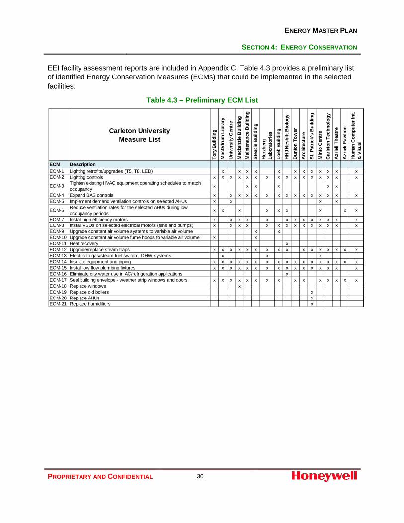
EEI facility assessment reports are included in Appendix C. Table 4.3 provides a preliminary list of identified Energy Conservation Measures (ECMs) that could be implemented in the selected facilities.
Table 4.3 – Preliminary ECM List
Carleton UniversityMeasure List
Tory
Bui
ldin
gM
acO
drum
Lib
rary
Uni
vers
ity C
entr
eM
acke
nzie
Bui
ldin
gM
aint
enan
ce B
uild
ing
Stea
cie
Bui
ldin
gH
erzb
erg
Labo
rato
ries
Loeb
Bui
ldin
gH
HJ
Nes
bitt
Bio
logy
Dun
ton
Tow
erA
rchi
tect
ure
St. P
atric
k's
Bui
ldin
gM
into
Cen
tre
Car
leto
n Te
chno
logy
Azr
ieli
Thea
tre
Azr
ieli
Pavi
lion
Hum
an C
ompu
ter I
nt.
& V
isua
l
ECM DescriptionECM-1 Lighting retrofits/upgrades (T5, T8, LED) x x x x x x x x x x x xECM-2 Lighting controls x x x x x x x x x x x x x x x x
ECM-3 Tighten existing HVAC equipment operating schedules to match occupancy x x x x x x
ECM-4 Expand BAS controls x x x x x x x x x x x x x x xECM-5 Implement demand ventilation controls on selected AHUs x x x x
ECM-6 Reduce ventilation rates for the selected AHUs during low occupancy periods x x x x x x x x x
ECM-7 Install high efficiency motors x x x x x x x x x x x x xECM-8 Install VSDs on selected electrical motors (fans and pumps) x x x x x x x x x x x x x xECM-9 Upgrade constant air volume systems to variable air volume x xECM-10 Upgrade constant air volume fume hoods to variable air volume x xECM-11 Heat recovery xECM-12 Upgrade/replace steam traps x x x x x x x x x x x x x x x xECM-13 Electric to gas/steam fuel switch - DHW systems x x xECM-14 Insulate equipment and piping x x x x x x x x x x x x x x x x xECM-15 Install low flow plumbing fixtures x x x x x x x x x x x x x x x xECM-16 Eliminate city water use in AC/refrigeration applications xECM-17 Seal building envelope - weather strip windows and doors x x x x x x x x x x x x x x xECM-18 Replace windows xECM-19 Replace old boilers xECM-20 Replace AHUs xECM-21 Replace humidifiers x

ENERGY MASTER PLAN
APPENDICES
PROPRIETARY AND CONFIDENTIAL 31
Appendices Appendix A Utility Data Management
Appendix B University Campus Electrical Distribution Report
Appendix C Facility Walkthrough Reports
Appendix D Energy Master Plan Analysis – Utility Summaries and Other Supporting Information (attached on CD)

ENERGY MASTER PLAN
APPENDICES
PROPRIETARY AND CONFIDENTIAL 32
Appendix A
Utility Data Management

ENERGY MASTER PLAN
APPENDICES
PROPRIETARY AND CONFIDENTIAL
Capturing the building operating data is the first step toward improved management of the campus facilities. Analysis of this data and follow up actions constitute the second and third steps in driving operational excellence. Observations of areas where corrective actions are recommended, are outlined as follows: General utility billing management
• No easy access to historical utility billing information o Longer than expected wait time to receive the required information slowed down
Honeywell analysis • Incomplete billing
o Data received still incomplete with many missing bills especially for natural gas accounts (e.g. most bills missing from March to September 2012)
o For the purpose of this analysis the consumption data for missing periods have been estimated based on the meter readings from available bills
Enbridge Consolidated Gas Account #000000655320
• Group account for 14 facilities listed in Table 2.2 • Shows the most inconsistent consumption data from all accounts analyzed:
o Numerous meter reading errors o Meter readings frequently estimated not actual
some improvement in the frequency of actual meter readings observed in 2011 and 2012
o Billing error corrections and reversal of charges in many cases encompass several billing periods with over 2 years as an extreme example
Bldg. #11 Shed June 6, 2011 includes corrected charges all the way back to January 8, 2009
Billing errors may affect gas consumption forecasting and utility cost recovery from tenants
Corrected bills show $ credits but not corrected gas consumption. The corrected gas consumption has to be manually calculated by the university staff
• University Centre (#7) – potential service address error o As of December 4, 2012 this building service address has been changed to
Residence Commons (#19) resulting in 2 gas bills for the latter and none for the former
• Mackenzie Bldg. (#10) – very low gas use o Based on the available billing data the building total annual gas use range from
as low as 2 m3 in 2011 to as high as 66 m3 in 2009 o With almost no gas consumption, the University incurs an annual cost of over
$1,000 (in 2012) in “Customer Charges” just for having a meter o There may be an opportunity to eliminate this cost by investigating the source of
gas use and the real need for it in this building • Bldg. #11 Shed
o Shed meter service address is ambiguous as the University operating staff appear to be unfamiliar with the actual gas meter location
ENERGY MASTER PLAN
APPENDICES
PROPRIETARY AND CONFIDENTIAL
o The meter’s “Bldg. #11 Shed” label may also be misleading as to the true end use for the gas used
Water Accounts
• Historically two out of four water accounts (Table 2.1) recorded the majority of water consumption on campus, namely accounts #0055-2520-10 and #0055-2522-10
o These 2 accounts appear to match the two feed lines from City of Ottawa and associated meters located in the meter chamber on Colonel By Drive and serving the campus water distribution system
o All four accounts have the same service address but the location of the remaining 2 meters is currently not clear
• Historical trend of annual water consumption on campus shows a steady growth in consumption from 2009 to 2011
• This trend was sharply reversed in 2012 when the total annual water consumption dropped by about 22% compared to 2011
o This drop in water consumption coincides with: Account #0055-2523-10 and associated meter becoming dormant. No
metered water consumption since May 2011 New water account #1107-2620-01 established sometime in 2012.
Honeywell has received only 2 bills for this account for water consumption in November and December
o No further evidence is available to account for potential reasons for the reduction in water consumption in 2012

ENERGY MASTER PLAN
APPENDICES
PROPRIETARY AND CONFIDENTIAL
Appendix B
University Campus Electrical Distribution Report

Carleton University Campus Electrical Distribution Report
4 October 2013 INTRODUCTION Chorley + Bisset Ltd was retained by Honeywell to conduct a high level review of the campus electrical distribution system and capacity at Carleton University, 1125 Colonel By Drive, Ottawa, Ontario. This report is intended to provide guidance with respect to condition and capacity of normal power distribution at this campus with regards for planned future expansion. The details presented are the results of our initial review only and does not include detailed observations or data on actual system performance from the facility Owner. It is not intended to present the results of a comprehensive audit and inspection of all equipment and systems in the facility. As an example, concealed systems, conduit, wiring and equipment located within walls, below floors or above ceiling spaces, and secured areas, etc, were not accessible for review. This report is also not intended to provide a performance guarantee that existing systems or equipment is fully operational, or will remain fully operational for the anticipated lifetime of the buildings. EXECUTIVE SUMMARY The majority of the electrical distribution systems in original buildings on campus have main electrical infrastructure that is not in compliance with current codes and applicable standards. The existing electrical peak demand of the campus is near the maximum capacity of the current substation. Additional electrical load on campus will require modifications to increase available electrical distribution. Four options for increasing electrical distribution system capacity are presented for discussion: Expansion of existing Bronson Avenue substation, addition of second substation at opposite end of campus, removal of residences from campus distribution, and installation of co-generation plant. ELECTRICAL INFRASTRUCTURE Campus Distribution Electrical service to the campus is provided by two underground 13.8kV feeders supplied from Hydro Ottawa along Bronson Avenue. These feeders supply the Carleton substation adjacent to the Recreation Centre (See 1 on attached Drawing ESK-1). Power is distributed throughout campus on 13.8kV loop feeders originating at the Bronson Avenue substation. In 2010, three loop feeders were split into five to increase capacity

available to each building. However, total campus capacity was not increased at this time. New cable installed in 2010 has increased ampacity over the existing cable; however the smaller original lead cable and loop switches limit the capacity of the feeders. According to drawings from 2002, Hydro Ottawa has a maximum supply capacity of 16MVA. Current campus peak demand from Hydro Ottawa billing is 14.7MVA. The campus master plan nearly doubles the floor area on campus which will net a future peak demand larger than current supply capacity. Building Distribution In general, many of the older buildings on campus have original substations which are silicon filled, but were formerly PCB liquid cooled transformers. No PCB liquid filled transformers were observed on campus. In some cases, PCBs will leach out of the core/coil and overtime these transformers could be considered contaminated. These installations comply with current Ministry of Environment regulations. However, in some locations oil was observed on the floor of the electrical room. This is an indication of possible leaks from liquid filled transformers or PILC pot-heads. In both cases, this can lead to equipment failure. Many of the original installations do not meet current Ontario Electrical Safety Code requirements with regards to spacing and exiting around equipment and limiting access to Medium Voltage equipment to authorized personnel only. The existing equipment is most likely not rated to interrupt or withstand the fault current available. Should a fault occur a nearby worker could be seriously injured due to space constraints and the resulting uncontained arc flash. Equipment damage can also result in building downtime. In addition, replacement parts may be difficult and/or expensive to source extending building downtime. In some cases, transformers were observed significantly larger than the building demand, due to energy reduction measures. This is inefficient as no-load losses are proportional to the size of the transformer. Step-up transformers were observed with delta secondary configuration without ground detection lights. Should a ground-fault on the secondary side occur, it would go unnoticed until a second ground-fault occurs. For this reason, this installation is no longer permitted by the Ontario Electrical Safety Code. Existing main services should be considered for replacement at the time of building renovation and/or addition. Replacement should be deferred, where possible, to avoid replacing equipment which may suit future plans for the building. For example, a 480V service could be replaced with a 600V service at the same time the mechanical systems are replaced. To address the delta secondary configurations, electrical systems should be reconfigured to eliminate delta secondary configurations. In the interim, ground detection lights need to be installed. UPGRADING OPTIONS ELECTICAL INFRASTRUCTURE The options listed below are not intended to be conclusive of all the available options to upgrade the electrical infrastructure required for the proposed buildings. Review and comment from Hydro Ottawa is required before accepting or eliminating any of the options.

Option 1 – Expansion of Existing Substation Option 1 doubles the size of the existing substation along Bronson Avenue (See 1 on attached Drawing ESK-1) to accommodate the planned future campus demand. Two new feeders from Hydro Ottawa would be brought to the new substation. In addition, it would be suggested that an additional standby feeder from Hydro Ottawa be included for redundancy. New loop feeders would be installed to service new buildings at the North end of the campus. Existing feeders would be further split and/or replaced to meet the demands in the existing campus. Option 2 – Addition of Second Substation at Opposite End of Campus Option 2 provides a second substation at the opposite end of the campus near MacOdrum Library or the existing residences (See 2a and 2b on attached Drawing ESK-1). This substation could be fed from Hydro Ottawa feeders entering into the campus on Colonel By Drive. Provided Hydro Ottawa circuits are able to take a different route than the existing feeders, redundancy is provided in the event of a utility pole collision, storm or localized Hydro Ottawa disturbance. A minimum of two new Hydro Ottawa feeders to the new substation would be required. As with option 1 above, an additional standby feeder from Ottawa Hydro should be provided at each substation for redundancy. New loop feeders would be installed to service new buildings at the North end of the campus. Existing loop feeders could be reworked to originate at the exiting Bronson substation and the new substation. This would allow the campus to be fed from either substation. With this arrangement, special attention to the campus key-interlock is required to prevent inadvertently back feeding Hydro Ottawa circuits. The main benefit of having two geographically isolated substations, with loop feeders originating at each, is redundancy. Currently a catastrophic failure at the Bronson Avenue substation would render the entire campus without power for a significant amount of time. Such catastrophic failures may be caused internally by fire or arc faults or externally by weather, floods or earthquakes. By changing open points in the loop feeders and shedding or rotating non-necessary loads (i.e. chillers); the entire campus can remain operational after a catastrophic event, at a reduced level of service. Option 3 – Remove Residences from Campus Distribution This option takes advantage of the close proximity of the residences to each other and to Colonel By Drive. From a site review, it appears Hydro Ottawa has existing underground utilities along Colonel By Drive which may be upgradable to support the residence buildings (See 3 on attached Drawing ESK-1). The existing residences are currently fed from the campus 13.8kV system. In this option, all new and existing residences are removed from the campus 13.8kV system to free up capacity for new academic buildings. New services could be provided for each building directly from Hydro Ottawa. Pad mount transformers owned by Hydro Ottawa serving one or more residence buildings would be installed in close proximity to the residence buildings. The medium voltage feeders could be owned by Hydro Ottawa or Carleton University. With this option, main

distribution boards may have to be altered to accommodate utility metering as each building would be a separate Hydro Ottawa meter. The primary benefit of this option is that the service uptime would remain Hydro Ottawa’s responsibility. Should a transformer failure occur Hydro Ottawa would be required to replace the transformer. Given that Hydro Ottawa stocks transformers, service could be restored quicker than if the transformers were owned by Carleton University. Service uptime is very important, considering the nature of the residence buildings. Option 4 – Install Co-Generation Heating Plant Installation of a co-generation heating plant could allow for replacement of the existing campus boilers while also providing the additional power required (See 4 on attached Drawing ESK-1). The co-generation would run parallel with the incoming electrical grid from Hydro Ottawa. Any power produced in excess of current demand would be sold back to the grid. Interlocked controls would have to be provided to set the electrical production from the co-generation plant as a function of the loading on existing incoming Hydro Ottawa feeders, and for remote shutdown of the co-generation system by Hydro Ottawa for safety purposes. There are many arrangements of co-generation plant, ranging in cost, payback and risk. Further study and risk assessment on the arrangements should be completed. For example, in the case of 100% reliance on the co-generation plant for electrical power without upgrading feeders from Hydro Ottawa, a failure in the heating plant could result in a cascading effect and loss of electrical service to the entire campus. Option 4 used in conjunction with the previous options could provide a viable solution to meet the campus thermal and electrical power requirements, and provide opportunities to peak shave. The co-generation plant could also allow limited backup power to the entire campus during an extended Hydro Ottawa outage.
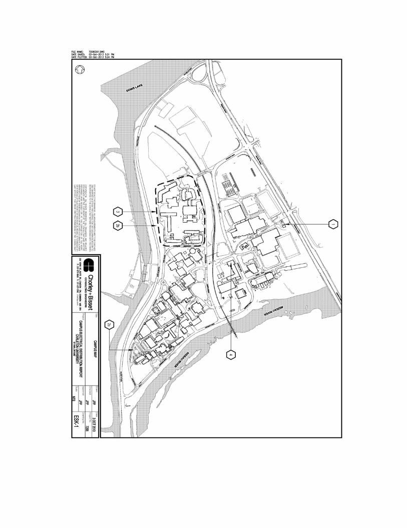

ENERGY MASTER PLAN
APPENDICES
PROPRIETARY AND CONFIDENTIAL
Appendix C
Facility Walkthrough Reports

CARLETON UNIVERSITY
Energy Savings Generator –
Carleton University 1125 Colonel Bay Drive,
Ottawa, ON K1S 5B6
Prepared By:
519-624-9965 www.ee-solutions.com

CARLETON UNIVERSITY
SUMMARY OF OPPORTUNITY ASSESMENT PAGE 1
Table 1. ASHRAE Level 1 ‐ Energy and Water Conservation Opportunity Assessment
Facility #
Facility Name Measure #
Measure Electricity (kW)
Electricity (kWh)
Steam (Gas Fired) (klb)
Natural Gas (m³)
Water (m³) Annual Total Energy Savings ($)
Annual Tonnes CO2
Total cost ($) Simple Payback
1 Tory Building 1 Lighting Controls: Occupancy Sensors 0.00 243600.67 0.00 0.00 0.00 23,190.78$ 182.94 138,542.01$ 5.971 Tory Building 2 Install VFD's on Heating Hot Water Return Pumps 0.00 16695.62 0.00 0.00 0.00 1,589.42$ 12.54 18,837.90$ 11.851 Tory Building 3 Install VFD's on AHU‐6 (Eng Air heating/cooling unit) 0.00 28459.16 0.00 0.00 0.00 2,709.31$ 21.37 15,061.05$ 5.561 Tory Building 4 Install VFD's on Domestic Water Booster Pumps (10HP) 0.00 31171.76 0.00 0.00 0.00 2,967.55$ 23.41 8,610.56$ 2.901 Tory Building 5 Install Variable Speed Fume Hood Exhaust Fans (where possible) 0.00 735.70 71.70 0.00 0.00 1,384.28$ 4.45 13,359.11$ 9.651 Tory Building 6 Install VFD on AHU‐4, Lecture Hall 0.00 3678.29 0.00 0.00 0.00 350.17$ 2.76 5,936.92$ 16.951 Tory Building 7 Implement Demand Control Ventilation on AHU‐4, ‐6 0.00 618.91 78.58 5976.17 0.00 3,172.63$ 15.75 6,723.09$ 2.121 Tory Building 8 Re‐Schedule AHU‐3 (Currently 24/7), Cycle On/Off based on Temperature 0.00 127175.69 0.00 0.00 0.00 12,107.13$ 95.51 335.60$ 0.031 Tory Building 11 Implement "Partial Occupancy" Schedule on AHU‐1, ‐2, ‐3 0.00 1517.84 825.47 0.00 0.00 15,275.44$ 46.04 699.17$ 0.051 Tory Building 12 Water Conservation: Ultra Low Flow Aerators 0.00 0.00 42.39 0.00 453.28 2,075.24$ 2.31 1,077.66$ 0.52Tory Building Total 0.00 453653.66 1018.15 5976.17 453.28 64,821.97$ 407.07 209,183.08$ 3.23
2 Macodrum Library 1 Lighting Upgrade: Replace Magnetic Ballasts in West End 121.42 489564.23 0.00 0.00 0.00 47,368.96$ 367.66 601,338.89$ 12.692 Macodrum Library 3 Domestic Hot Water Conversion: Electric To Steam 0.00 3786.09 ‐13.64 0.00 0.00 110.42$ 2.10 22,627.31$ 204.922 Macodrum Library 4 Commission New Mechanical Room when Complete 0.00 791.97 106.55 0.00 0.00 2,028.55$ 6.39 47,566.10$ 23.452 Macodrum Library 5 Implement "Partial Occupancy" Schedule on AHU's 0.00 3480.70 229.02 0.00 0.00 4,529.27$ 15.07 3,495.86$ 0.772 Macodrum Library 6 Water Conservation: Ultra Low Flow Aerators 0.00 7355.82 0.00 0.00 268.44 1,469.08$ 5.52 1,390.53$ 0.95Macodrum Library Total 121.42 504978.81 321.93 0.00 268.44 55,506.29$ 396.74 676,418.71$ 12.19
7 University Centre 1 Lighting Controls: Occupancy Sensors 0.00 222346.89 0.00 0.00 0.00 21,167.42$ 166.98 129,864.88$ 6.147 University Centre 3 Water Conservation: Ultra Low Flow Aerators 0.00 0.00 16.01 0.00 171.24 783.98$ 0.87 1,981.51$ 2.537 University Centre 4 Install VFD's on AHU‐1, AHU‐2, AHU‐3 Supply Fans, AHU‐5, AHU‐6 0.00 97179.92 0.00 0.00 0.00 9,251.53$ 72.98 76,713.72$ 8.297 University Centre 5 Implement Demand Control Ventilation on AHU‐1, AHU‐2, AHU‐3, AHU‐4, A 0.00 6007.69 2012.51 8153.48 0.00 39,744.19$ 128.99 36,977.02$ 0.93University Centre Total 0.00 325534.50 2028.52 8153.48 171.24 70,947.12$ 369.83 245,537.13$ 3.46
10 CJ Mackenzie 1 Lighting Upgrade: High Performance T8 Retrofit 4.50 39325.86 0.00 0.00 0.00 3,772.09$ 29.53 22,294.69$ 5.9110 CJ Mackenzie 2 Lighting Controls: Occupancy Sensors 0.00 313119.11 0.00 0.00 0.00 29,808.94$ 235.15 168,025.21$ 5.6410 CJ Mackenzie 3 Water Conservation: Ultra Low Flow Aerators 0.00 0.00 25.61 0.00 273.80 1,253.54$ 1.39 709.50$ 0.5710 CJ Mackenzie 4 Replace current single pane windows 0.00 0.00 650.41 0.00 0.00 11,922.08$ 35.38 744,904.42$ 62.4810 CJ Mackenzie 5 Install VFD's on Remaining AHU's, Reset to Outdoor Air Temperature 0.00 213161.15 0.00 0.00 0.00 20,292.94$ 160.08 173,851.08$ 8.5710 CJ Mackenzie 6 Implement "Partial Occupancy" Schedule on AHU's 0.00 1636.30 608.12 0.00 0.00 11,302.60$ 34.31 3,495.86$ 0.31
CJ Mackenzie Total 4.50 567242.42 1284.14 0.00 273.80 78,352.19$ 495.84 1,113,280.77$ 14.2111 Maintenance Building 1 Install Steam Control Valve on DHW‐1 0.00 0.00 47.18 0.00 0.00 864.87$ 1.19 2,829.14$ 3.2711 Maintenance Building 2 Install VFD's on AHU‐11A2 and 11A3 0.00 12762.04 0.00 0.00 0.00 1,214.95$ 2.25 19,351.46$ 15.9311 Maintenance Building 3 Implement "Partial Occupancy" Schedule 0.00 5.80 116.54 968.12 0.00 2,407.77$ 4.73 3,495.86$ 1.4511 Maintenance Building 4 Optimal start/stop of RTU‐U1‐Admin 0.00 1322.21 21.91 0.00 0.00 527.52$ 0.79 194.14$ 0.3711 Maintenance Building 5 Lighting Upgrade: High Performance T8 Retrofit 196.68 96215.00 0.00 0.00 0.00 10,394.73$ 17.00 81,182.98$ 7.8111 Maintenance Building 6 Lighting Upgrade: LED Exit Signs 1.62 1179.36 0.00 0.00 0.00 122.45$ 0.21 509.42$ 4.1611 Maintenance Building 7 Lighting Upgrade: T5HO 16.08 11697.50 0.00 0.00 0.00 1,214.58$ 2.07 6,360.82$ 5.2411 Maintenance Building 8 Lighitng Controls: Occupancy Sensors 0.00 41088.39 0.00 0.00 0.00 3,911.61$ 7.25 29,899.66$ 7.6411 Maintenance Building 9 Water Conservation: Install Ultra Low Flow 0.5 gpm Faucet Aerators 0.00 0.00 11.31 0.00 205.55 795.96$ 0.29 486.69$ 0.61
Maintenance Building Total 214.38 164270.30 196.94 968.12 205.55 21,454.44$ 35.77 144,310.18$ 6.73

CARLETON UNIVERSITY
SUMMARY OF OPPORTUNITY ASSESMENT PAGE 2
Table 1. ASHRAE Level 1 ‐ Energy and Water Conservation Opportunity Assessment – cont’d
Facility #
Facility Name Measure #
Measure Electricity (kW)
Electricity (kWh)
Steam (Gas Fired) (klb)
Natural Gas (m³)
Water (m³) Annual Total Energy Savings ($)
Annual Tonnes CO2
Total cost ($) Simple Payback
12 Steacie Building 1 Implement Night Setback for AHU‐17 and 18 0.00 0.00 424.00 0.00 0.00 7,771.86$ 10.70 554.68$ 0.0712 Steacie Building 2 Recommissioning 0.00 26568.98 437.51 0.00 0.00 10,549.01$ 15.73 74,811.46$ 7.0912 Steacie Building 3 Install VAV Boxes 0.00 62907.72 0.00 0.00 0.00 5,988.82$ 11.10 109,330.42$ 18.2612 Steacie Building 4 Insulate Steam and Hot Water Piping 0.00 0.00 39.26 0.00 0.00 719.62$ 0.99 976.80$ 1.3612 Steacie Building 5 Lighting Upgrade: High Performance T8 Retrofit 292.68 124309.00 0.00 0.00 0.00 13,672.11$ 21.98 130,878.89$ 9.5712 Steacie Building 6 Lighting Upgrade: Incandescent to CFL 5.04 3646.24 0.00 0.00 0.00 378.77$ 0.64 129.07$ 0.3412 Steacie Building 7 Lighting Controls: Occupancy Sensors 0.00 34043.02 0.00 0.00 0.00 3,240.90$ 6.00 22,867.32$ 7.0612 Steacie Building 8 Water Conservation: Install Ultra Low Flow 0.5 gpm Faucet Aerators 0.00 0.00 19.18 0.00 373.58 1,421.53$ 0.48 556.21$ 0.39
Steacie Building Total 297.72 251474.97 919.95 0.00 373.58 43,742.61$ 67.63 340,104.86$ 7.7813 Herzberg Laboratories 1 Lighting Controls: Occupancy Sensors 0.00 238449.26 0.00 0.00 0.00 22,700.37$ 179.07 142,896.88$ 6.2913 Herzberg Laboratories 2 Install VFD's on AHU‐Level 2 B Block, AHU‐Level 3 B Block, AHU‐Level 4 B Blo 0.00 43520.81 0.00 0.00 0.00 4,143.18$ 32.68 42,905.64$ 10.3613 Herzberg Laboratories 3 Remove Variable Inlet Vanes, Install VFD on AHU‐Level 5 B Block 0.00 30486.37 0.00 0.00 0.00 2,902.30$ 22.89 19,569.75$ 6.7413 Herzberg Laboratories 4 Install VFD's on Remaining AHU's, Reset to Outdoor Air Temperature 0.00 45972.69 0.00 0.00 0.00 4,376.60$ 34.52 94,007.58$ 21.4813 Herzberg Laboratories 5 Implement "Partial Occupancy" Schedule on AHU's 0.00 834.06 393.94 0.00 0.00 7,300.28$ 22.05 4,894.21$ 0.6713 Herzberg Laboratories 6 Water Conservation: Ultra Low Flow Aerators 0.00 7254.49 0.00 0.00 264.74 1,448.85$ 5.45 1,147.19$ 0.7913 Herzberg Laboratories 8 DHW Conversion: Electric to Steam 0.00 3485.42 ‐12.56 0.00 0.00 101.65$ 1.93 22,627.31$ 222.6013 Herzberg Laboratories 9 Install VFD on Domestic Water Booster Pumps 0.00 16610.54 0.00 0.00 0.00 1,581.32$ 12.47 7,855.40$ 4.97
Herzberg Laboratories Total 0.00 386613.64 381.38 0.00 264.74 44,554.55$ 311.09 335,903.97$ 7.5415 Loeb 1 Lighting Controls: Occupancy Sensors 0.00 451861.06 0.00 0.00 0.00 43,017.17$ 339.34 217,385.75$ 5.0515 Loeb 2 Install VFD's on Induction Units A/B, C/D 0.00 122609.82 0.00 0.00 0.00 11,672.45$ 92.08 58,525.52$ 5.0115 Loeb 3 Install VFD's on Dual Temperature Pumps BA, BB 0.00 20708.28 0.00 0.00 0.00 1,971.43$ 15.55 11,135.13$ 5.6515 Loeb 4 Install VFD's on Chilled Water Pumps 0.00 94101.92 0.00 0.00 0.00 8,958.50$ 70.67 64,486.63$ 7.2015 Loeb 5 Install VFD on Domestic Water Booster Pumps 0.00 16610.54 0.00 0.00 0.00 1,581.32$ 12.47 15,710.80$ 9.9415 Loeb 6 Re‐Schedule AHU‐5 (Level 1 & 2, Currently 24/7), Cycle On/Off based on Te 0.00 64473.66 0.00 0.00 0.00 6,137.89$ 48.42 699.17$ 0.1115 Loeb 7 Lighting Upgrade: High Performance T8 Retrofit 50.49 147019.94 0.00 0.00 0.00 14,313.34$ 110.41 250,046.47$ 17.4715 Loeb 8 Implement "Partial Occupancy" Schedule on AHU's 0.00 2182.64 1084.74 0.00 0.00 20,091.03$ 60.64 1,747.93$ 0.0915 Loeb 9 Lighting Upgrade: Incandescent to CFL 0.71 2077.10 0.00 0.00 0.00 202.20$ 1.56 218.01$ 1.0815 Loeb 10 Water Conservation: Ultra Low Flow Aerators 0.00 0.00 52.78 0.00 564.38 2,583.92$ 2.87 1,807.69$ 0.70
Loeb Total 51.20 921644.95 1137.52 0.00 564.38 110,529.26$ 754.01 621,763.12$ 5.6316 HHJ Nesbitt 1 Lighting Controls: Occupancy Sensors 0.00 65540.32 0.00 0.00 0.00 6,239.44$ 49.22 38,848.66$ 6.2316 HHJ Nesbitt 2 Recommission Hot Water Pumps P‐8 and P‐9 VFD, Reading 9 Hz 0.00 8390.35 0.00 0.00 0.00 798.76$ 6.30 1,398.35$ 1.7516 HHJ Nesbitt 3 Install VFD on P‐12 to AHU‐2 & 3 0.00 5593.57 0.00 0.00 0.00 532.51$ 4.20 6,450.49$ 12.1116 HHJ Nesbitt 4 Install VFD on AHU‐4, Remove Bypass 0.00 7442.04 0.00 0.00 0.00 708.48$ 5.59 12,267.09$ 17.3116 HHJ Nesbitt 5 Implement "Partial Occupancy" Schedule on AHU‐1 0.00 110.24 40.97 0.00 0.00 761.44$ 2.31 349.59$ 0.4616 HHJ Nesbitt 6 Water Conservation: Replace Single Pass Dry‐O‐Tron Unit 0.00 0.00 0.00 0.00 994.80 2,849.12$ 0.00 11,613.93$ 4.0816 HHJ Nesbitt 7 Water Conservation: Ultra Low Flow Aerators 0.00 0.00 13.56 0.00 144.96 663.66$ 0.74 278.11$ 0.4216 HHJ Nesbitt 9 Install Heat Reclaim on AHU‐2 0.00 911.32 812.94 0.00 0.00 14,987.96$ 44.90 49,528.93$ 3.30
HHJ Nesbitt Total 0.00 87987.82 867.47 0.00 1139.76 27,541.36$ 113.26 120,735.14$ 4.38

CARLETON UNIVERSITY
SUMMARY OF OPPORTUNITY ASSESMENT PAGE 3
Table 1. ASHRAE Level 1 ‐ Energy and Water Conservation Opportunity Assessment – cont’d
Facility #
Facility Name Measure #
Measure Electricity (kW)
Electricity (kWh)
Steam (Gas Fired) (klb)
Natural Gas (m³)
Water (m³) Annual Total Energy Savings ($)
Annual Tonnes CO2
Total cost ($) Simple Payback
21 Dunton Tower 1 Recommission AHU‐3 0.00 1179.90 4.54 0.00 0.00 195.63$ 0.32 1,678.01$ 8.5821 Dunton Tower 3 Install VFD's on AHU‐3 and 4 0.00 11694.63 0.00 0.00 0.00 1,113.33$ 2.06 30,826.32$ 27.6921 Dunton Tower 4 Control P‐28 to Turn Off 0.00 4053.79 0.00 0.00 0.00 385.92$ 0.71 734.33$ 1.9021 Dunton Tower 5 Static Pressure Reset Control for AHU‐1 and 2 0.00 30871.16 0.00 0.00 0.00 2,938.93$ 5.44 12,753.14$ 4.3421 Dunton Tower 6 Lighting Upgrade: T8 High Perfromance System 61.80 314945.63 0.00 0.00 0.00 30,370.90$ 55.68 306,084.99$ 10.0821 Dunton Tower 7 Lighting Upgrade: LED Retrofit 3.70 11095.85 0.00 0.00 0.00 1,079.56$ 1.96 6,734.26$ 6.2421 Dunton Tower 8 Lighting Controls: Occupancy Sensors 0.00 240657.00 0.00 0.00 0.00 22,910.55$ 42.44 161,656.41$ 7.0621 Dunton Tower 9 Water Conservation: Install Ultra Low Flow 0.5 gpm Faucet Aerators 0.00 0.00 31.56 0.00 573.72 2,221.69$ 0.80 2,815.83$ 1.27
Dunton Tower Total 65.50 614497.95 36.11 0.00 573.72 61,216.50$ 109.43 523,283.29$ 8.5522 Architecture Building 1 Install Control Valves on Steam Supply 0.00 0.00 40.60 0.00 0.00 744.18$ 1.02 3,989.24$ 5.3622 Architecture Building 2 Replace VIV's with VFD's on AHU‐1 Supply and Return Fans 0.00 19954.78 0.00 0.00 0.00 1,899.70$ 3.52 25,773.39$ 13.5722 Architecture Building 3 Replace VIV with VFD on AHU‐2 Return Fan 0.00 4291.07 0.00 0.00 0.00 408.51$ 0.76 9,498.92$ 23.2522 Architecture Building 5 Lighting Upgrade: Incandescent to CFL 0.88 7679.09 0.00 0.00 0.00 736.58$ 1.36 268.66$ 0.3622 Architecture Building 6 Install Demand Control Ventilation on AHU's 0.00 36735.18 845.95 5086.38 0.00 20,427.63$ 37.20 22,788.65$ 1.1222 Architecture Building 7 Replace Decommissioned Pump Housings with Insulated Straight Piping 0.00 10.97 0.00 0.00 2.13 7.13$ 0.00 121.27$ 17.0022 Architecture Building 8 Lighting Controls: Occupancy Sensors 0.00 54520.27 0.00 0.00 0.00 5,190.33$ 9.62 36,623.56$ 7.0622 Architecture Building 9 Water Conservation: Install Ultra Low Flow 0.5 gpm Faucet Aerators 0.00 0.00 21.69 0.00 173.93 895.68$ 0.55 764.79$ 0.85
Architecture Building Total 0.88 123191.36 908.24 5086.38 176.05 30,309.73$ 54.03 99,828.48$ 3.2923 St Patrick's 1 Replace HP‐2 Boilers B‐1 to B‐3 0.00 0.00 0.00 4084.39 0.00 1,143.63$ 7.52 53,734.60$ 46.9923 St Patrick's 2 Install Proper Controls on AHU‐2, HP‐2, SP‐3 and CH‐2 0.00 3976.82 54.23 352.01 0.00 1,471.17$ 2.72 32,786.28$ 22.2923 St Patrick's 3 Replace B‐4 with Gas Fired Humidifier 0.00 0.00 0.00 7540.89 0.00 2,111.45$ 13.89 37,012.64$ 17.5323 St Patrick's 4 Replace AHU‐2 with a Proper HVAC Unit Designed for Art Galleries 0.00 68569.30 135.57 0.00 0.00 9,012.84$ 15.52 648,477.91$ 71.9523 St Patrick's 5 Install Demand Control Ventilation and Optimize Schedule of AHU‐1 0.00 59779.51 0.00 9012.97 0.00 8,214.64$ 27.15 9,080.15$ 1.1123 St Patrick's 6 Replace AHU‐1 Return Fan VIVs with VFD 0.00 9537.27 0.00 0.00 0.00 907.95$ 1.68 12,005.23$ 13.2223 St Patrick's 7 Lighting Upgrade: T8 High Performance System 21.52 109690.00 0.00 0.00 0.00 10,577.62$ 19.39 106,604.76$ 10.0823 St Patrick's 8 Lighting Upgrade: LED Retrofit 14.48 66519.08 0.00 0.00 0.00 6,423.54$ 11.76 29,291.19$ 4.5623 St Patrick's 9 Lighting Controls: Occupancy Sensors 0.00 85533.52 0.00 0.00 0.00 8,142.79$ 15.09 57,455.40$ 7.0623 St Patrick's 10 Water Conservation: Install Ultra Low Flow 0.5 gpm Faucet Aerators 0.00 0.00 27.25 0.00 437.04 1,751.16$ 0.69 625.74$ 0.36
St Patrick's Total 36.00 403605.49 217.05 20990.26 437.04 49,756.79$ 115.41 987,073.90$ 19.8427 Minto Centre 1 Lighting Upgrade: High Performance T8 Retrofit 51.12 186063.08 0.00 0.00 0.00 18,034.19$ 139.73 253,159.77$ 14.0427 Minto Centre 3 Lighting Controls: Occupancy Sensors 0.00 204012.71 0.00 0.00 0.00 19,422.01$ 153.21 105,111.78$ 5.4127 Minto Centre 4 DHW Conversion: Electric to Steam 0.00 4710.03 ‐16.97 0.00 0.00 137.36$ 2.61 22,627.31$ 164.7327 Minto Centre 5 Install VFD's on Heating Hot Water Pumps 0.00 5593.57 0.00 0.00 0.00 532.51$ 4.20 6,450.49$ 12.1127 Minto Centre 6 Install VFD's on Chilled Water Pumps 0.00 20791.51 0.00 0.00 0.00 1,979.35$ 15.61 24,254.40$ 12.2527 Minto Centre 7 Remove Variable Inlet Vanes, Replace with VFD: AHU‐1, ‐7 & ‐8 0.00 98921.01 0.00 0.00 0.00 9,417.28$ 74.29 58,745.53$ 6.2427 Minto Centre 8 Install VFD's on Remaining AHU's 0.00 53286.81 0.00 0.00 0.00 5,072.90$ 40.02 47,014.40$ 9.2727 Minto Centre 9 Implement Demand Control Ventilation for AHU‐3 (Strong Room), AHU‐5 (T 0.00 1574.57 184.59 0.00 0.00 3,533.45$ 11.22 5,932.10$ 1.6827 Minto Centre 10 Implement "Partial Occupancy" Schedule on AHU's 0.00 1622.83 314.75 0.00 0.00 5,923.90$ 18.34 1,747.93$ 0.3027 Minto Centre 11 Water Conservation: Ultra Low Flow Aerators 0.00 9150.91 0.00 0.00 333.95 1,827.59$ 6.87 1,042.90$ 0.57
Minto Centre Total 51.12 585727.05 482.37 0.00 333.95 65,880.55$ 466.11 526,086.61$ 7.99

CARLETON UNIVERSITY
SUMMARY OF OPPORTUNITY ASSESMENT PAGE 4
Table 1. ASHRAE Level 1 ‐ Energy and Water Conservation Opportunity Assessment – cont’d
Facility #
Facility Name Measure #
Measure Electricity (kW)
Electricity (kWh)
Steam (Gas Fired) (klb)
Natural Gas (m³)
Water (m³) Annual Total Energy Savings ($)
Annual Tonnes CO2
Total cost ($) Simple Payback
29 Carleton Tech & Training Centre 1 Install Steam Valves on HPS Side of PRV's When No Heating is Required 0.00 0.00 115.44 0.00 0.00 2,116.03$ 0.01 3,393.85$ 1.6029 Carleton Tech & Training Centre 2 Repair Steam Leak on HPS Side 0.00 0.00 132.45 0.00 0.00 2,427.83$ 0.01 1,380.44$ 0.5729 Carleton Tech & Training Centre 3 Install VFD's on P‐1 and P‐2 0.00 27165.02 0.00 0.00 0.00 2,586.11$ 4.79 23,977.99$ 9.2729 Carleton Tech & Training Centre 4 Repair Fresh Air Damper on MAU‐1 0.00 0.00 26.86 0.00 0.00 492.40$ 0.00 2,240.54$ 4.5529 Carleton Tech & Training Centre 5 Install VFD on MAU‐1 0.00 31430.76 0.00 0.00 0.00 2,992.21$ 5.54 22,969.07$ 7.6829 Carleton Tech & Training Centre 6 Repair RTU‐9 to Minimize Air Leakage From Building and Make Sure Dampe 0.00 0.00 5.34 0.00 0.00 97.96$ 0.00 309.12$ 3.1629 Carleton Tech & Training Centre 7 Tighten All Control Schedules 0.00 5467.92 49.29 0.00 0.00 1,424.06$ 0.97 1,678.01$ 1.1829 Carleton Tech & Training Centre 8 Lighting Upgrade: T8 High Performance System 20.23 103090.71 0.00 0.00 0.00 9,941.27$ 18.22 100,190.36$ 10.0829 Carleton Tech & Training Centre 9 Lighting Upgrade: Interior LED's 2.57 8001.00 0.00 0.00 0.00 777.83$ 1.42 4,522.00$ 5.8129 Carleton Tech & Training Centre 10 Lighting Controls: Occupancy Sensors 0.00 75075.34 0.00 0.00 0.00 7,147.17$ 13.24 51,103.44$ 7.1529 Carleton Tech & Training Centre 11 Water Conservation: Install Ultra Low Flow 0.5 gpm Faucet Aerators 0.00 0.00 17.68 0.00 283.49 1,135.91$ 0.00 973.37$ 0.86
Carleton Tech & Training Centre Total 22.80 250230.75 347.07 0.00 283.49 31,138.79$ 44.21 212,738.20$ 6.8331 Azrieli Theatre 1 Install Demand Control Ventilation for AHU‐1, 2 and 3 0.00 13.61 211.67 0.00 0.00 3,881.13$ 5.35 15,417.42$ 3.9731 Azrieli Theatre 2 Install VFD's on AHU‐1 and 3 0.00 37157.03 0.00 0.00 0.00 3,537.35$ 6.55 37,404.22$ 10.5731 Azrieli Theatre 3 Reschedule All Air Handling Units 0.00 19818.71 34.40 0.00 0.00 2,517.21$ 4.36 2,053.12$ 0.8231 Azrieli Theatre 4 Lighting Controls: Occupancy Sensors 0.00 57654.00 0.00 0.00 0.00 5,488.66$ 10.17 31,178.96$ 5.6831 Azrieli Theatre 5 Lighting Upgrade: T8 High Performance System 11.70 42511.00 0.00 0.00 0.00 4,120.52$ 7.52 57,841.05$ 14.0431 Azrieli Theatre 6 Water Conservation: Install Ultra Low Flow 0.5 gpm Faucet Aerators 0.00 5997.48 0.00 0.00 248.05 1,281.38$ 1.06 1,112.43$ 0.87
Azrieli Theatre Total 11.70 163151.83 246.06 0.00 248.05 20,826.25$ 35.01 145,007.20$ 6.9632 Azrieli Pavilion 2 Implement "Partial Occupancy" Schedule on AHU 0.00 154.27 42.52 0.00 0.00 793.99$ 2.43 699.17$ 0.88
Azrieli Pavilion Total 0.00 154.27 42.52 0.00 0.00 793.99$ 2.43 699.17$ 0.8837 Human Computer Interaction Building 1 Install VFD's on P‐1 and 2, Open Balancing Valves on Pumps and Chiller 0.00 5926.79 0.00 0.00 0.00 564.23$ 1.05 6,886.32$ 12.2037 Human Computer Interaction Building 2 Install VFD's on P‐5 and 6, Open Balancing Valves on Pumps and Chiller 0.00 21073.02 0.00 0.00 0.00 2,006.15$ 3.72 22,683.14$ 11.3137 Human Computer Interaction Building 3 Open Balancing Valves on P‐3 and 4, Set Pump Speed on Valve Positions on 0.00 8768.08 0.00 0.00 0.00 834.72$ 1.55 2,358.54$ 2.8337 Human Computer Interaction Building 4 Install VFD on Cooling Tower Fan 0.00 3887.28 0.00 0.00 0.00 370.07$ 0.69 14,900.82$ 40.2637 Human Computer Interaction Building 5 Open Balancing Valves on P‐7 and 8, Control Flow with Existing VFD's 0.00 2716.22 0.00 0.00 0.00 258.58$ 0.48 2,358.54$ 9.1237 Human Computer Interaction Building 6 Implement "Partial Occupancy" Schedule on AHU's 1 and 2 0.00 25.91 367.81 0.00 0.00 6,744.35$ 9.29 1,398.35$ 0.2137 Human Computer Interaction Building 7 Lighting Upgrade: T8 High Performance System 0.02 142.97 0.00 0.00 0.00 13.71$ 0.03 81.04$ 5.9137 Human Computer Interaction Building 8 Lighitng Controls: Install Occupancy Sensors 0.00 89571.19 0.00 0.00 0.00 8,527.18$ 15.80 72,132.78$ 8.4637 Human Computer Interaction Building 9 Water Conservation: Install Ultra Low Flow 0.5 gpm Faucet Aerators 0.00 0.00 20.08 0.00 182.53 890.89$ 0.51 417.16$ 0.47
Human Computer Interaction Building Total 0.02 132111.45 387.89 0.00 182.53 20,209.88$ 33.09 123,216.69$ 6.10Grand Total 877.23 5936071.22 10823.30 41174.41 5949.61 797,582.25$ 3810.95 6,425,170.47$ 8.06

CARLETON UNIVERSITY
TORY BUILDING PAGE 1
1.0 Tory Building (#1) - Existing Building Profile
The facility is a 127,581 ft2, 5 story building which serves primarily as offices along with some classroom and auditorium spaces.
Heating
Heat to the building is provided by the campus’ centralized steam plant via shell and tube heat exchangers. Hot water from the heat exchanger then supplies a perimeter heating loop as well as hot water coils in the building’s four main air handling units.
Domestic Hot Water (DHW)
Domestic hot water to the facility is supplied by an instantaneous heat exchanger which draws from the University’s centralized steam plant.
Cooling
The entire facility is supplied with air conditioning.
It is equipped with two large McQuay chillers and a cooling tower. The chilled water plant serves several other buildings as well as the Tory Building.
Ventilation
The Tory Building is supplied with ventilation from the building’s three main air handling units located in penthouse mechanical rooms across the roof. Each AHU is equipped with a hot water and a chilled water heating coil to provide conditioned air as well as ventilation throughout the building.
CO2 levels are monitored by the BAS which adjusts the outdoor air ventilation levels to maintain indoor air quality. This allows ventilation levels to be minimized, especially during unoccupied overnight and weekend hours.
The supply and return fans of AHU-1, AHU-2 and AHU-3 are equipped with variable speed drives.
Water Fixtures
Water fixtures at the facility consist primarily of low flow flushometer toilets and urinals as well as washroom sinks with aerators. No running/leaking fixtures or damaged aerators were observed.
Lighting
Most lighting throughout the facility has been upgraded to higher efficiency lamps and fixtures. Linear florescent lighting throughout offices, classrooms, corridors, stairwells and common spaces consisted mainly of efficient 32W T8 lamps with electronic ballasts as well as some upgraded areas containing efficient T5 lamps. Pot light fixtures were equipped with compact florescent lamps. Exit signs have been converted to
Steam to Hydronic Heat Exchanger
Steam to Hydronic Heat Exchanger

CARLETON UNIVERSITY
TORY BUILDING PAGE 2
LED’s. The majority of lighting is controlled by local wall switches.
2.0 Energy Savings Scenario
The Energy Savings Scenario consists of all Opportunities that are recommended based primarily on the energy and utility cost saving benefits.
M01 – Lighting Controls: Occupancy Sensors
M01.1 - Existing Conditions
Many of the building’s offices and classrooms are being controlled by local wall switches. In many cases lights remain on longer than the space is occupied.
M01.2 - Retrofit Conditions
We recommend installing occupancy sensors in many of the offices, classrooms, corridors, and storage rooms. Typical energy savings range from 30%-60%, depending on the pattern and frequency of room use. It is important that qualified contractors are familiar with all building code and by law requirements regarding the installation of occupancy sensors, lighting level requirements and fire code. Safety of occupants should always be addressed when determining suitable applications for occupancy sensors.
M02 – Install VFD on heating hot water return pumps
M02.1 - Existing Conditions
Two 3 hp pumps, OP1-1P1 and OP2-1P2, and three 5 hp pumps, P-3, P-5A and P-5B are heating zone return pumps. They circulate heating hot water throughout the building perimeter heating and heating coils in the AHU’s.
Pumps OP1-1P1, OP2-1P2 and P-5A, P-5B operate in a Primary/Stand-by configuration. One pump operates continuously, 24/7, while the secondary pump cycles on if the primary pump were to fail.
M02.2 - Retrofit Conditions
We recommend installing a variable frequency drive (VFD) and inverter duty motor on the primary heating hot water pumps. The VFD will allow the pump speed to modulate to match the heating loads on the system at all times. Drive speeds will modulate based on supply/return temperature differential. If the primary pump or the VFD were to fail the secondary pump would run during the repair of the primary pump or VFD.
The costing and payback for this measure include installing a VFD on the “primary” pump only. A VFD can also be installed on the secondary pump in this system. Installation of the VFD on the standby pump would approximately double the implementation cost of the measure. As the standby pump in this system operates only occasionally, however, the energy and dollars saved would not increase significantly. We recommend installing a VFD on the primary pump only to minimize installation costs and to provide the most attractive payback for the measure.
M03 – Install VFD on AHU-6 (Eng Air heating/cooling unit)
M03.1 - Existing Conditions
All of the buildings AHU’s are recirculatory mixing air handling units which bring in controlled amounts

CARLETON UNIVERSITY
TORY BUILDING PAGE 3
of ventilation air and blend it with return air before delivering it to specific areas of the facility. Each of the AHU’s is equipped with a hot water coil and a chilled water coil which provides heating and cooling.
The fans for each of these AHU’s is sized to supply adequate air flows during times of peak heating, cooling or ventilation load requirements. Some of the AHU’s are currently equipped with VFD’s to reduce air flows during off peak times. AHU-6, however, lacks any type of air flow control.
M03.2 - Retrofit Conditions
We recommend installing variable frequency drives (VFD’s) and inverter duty motors on the supply and return fans of AHU-6. Fan speeds will modulate to maintain space temperature set points in each zone of the air handling unit. As a space calls for heating, the heating control valve for the reheat coil will open. If space temperature cannot be maintained once the reheat coil has reached 100%, the fan speed will ramp up to provide more heat to the space.
M04 – Install VFD on Domestic Water Booster Pumps
M04.1 - Existing Conditions
Two 10 hp domestic water booster pumps supply the necessary water pressure for the building. One pump runs continuously while the other pump cycles on only during times of peak loads (high domestic water consumption). As this building consists mainly of office and classroom spaces, the domestic water load is likely fairly constant throughout the occupied hours. This results very short intervals of high demand when the second booster pump would be required.
M04.2 - Retrofit Conditions
We recommend installing a variable speed drive and inverter duty motor on the primary domestic booster pump. Any PRV’s on the main line leading to the mechanical room should be opened completely or entirely removed to reduce the system losses. A pressure sensor would be installed in the penthouse with the VFD modulating to maintain water pressure (say 20 psig) at that point.
As the second domestic water booster pump runs for only very short periods of time throughout the day, installing a VFD on this pump would significantly increase the implementation cost of this measure, but would not increase the savings proportionally.
The costing and payback for this measure include installing a VFD on the “primary” pump only. A VFD can also be installed on the secondary pump in this system. Installation of the VFD on the standby pump would approximately double the implementation cost of the measure. As the standby pump in this system operates only occasionally, however, the energy and dollars saved would not increase significantly. We recommend installing a VFD on the primary pump only to minimize installation costs and to provide the most attractive payback for the measure.
M05 – Install VFD on Fume Hood Exhaust Fans
M05.1 - Existing Conditions
The building’s exhaust fume hoods are currently scheduled to exhaust air 24 hours a day 7 days a week. The fans run at full speed even when they could be running slower.
By installing a VFD, less conditioned air will be exhausted resulting in less air needing to be conditioned.

CARLETON UNIVERSITY
TORY BUILDING PAGE 4
M05.2 - Retrofit Conditions
We recommend installing a variable frequency drives (VFD’s) and inverter duty motors on the fume hood exhaust fans. Fan speeds will modulate to maintain duct pressure set points in each zone of the exhaust fan. As a fume hood is opened the pressure will drop indicating a need to increase exhaust air, the fan speed will ramp up to exhaust more from the space.
M06 – Install VFD on AHU-4
M06.1 - Existing Conditions
AHU-4 is a mixed air unit which brings in controlled amounts of ventilation air and blend it with return air before delivering it to the theatre. The AHU is equipped with a hot water coil and a chilled water coil which provides heating and cooling.
The fans for this AHU are sized to supply adequate air flows during times of peak heating, cooling or ventilation load requirements.
M06.2 - Retrofit Conditions
We recommend installing variable frequency drives (VFD’s) and inverter duty motors on the supply and return fans of AHU-4. Fan speeds will modulate to maintain space temperature set points in each zone of the air handling unit. As a space calls for heating, the heating control valve for the reheat coil will open. If space temperature cannot be maintained once the reheat coil has reached 100%, the fan speed will ramp up to provide more heat to the space.
M07 – Implement Demand Control Ventilation on AHU-4, -6
M07.1 - Existing Conditions
The air-handling units AHU-4 and AHU-6 provide heating, cooling and ventilation to the building, blending fresh air and return air to a fixed mixed air temperature setpoint. This provides temperature and humidity control in the space, but tends to bring in more ventilation air than needed, especially during partial occupancy periods. Any outside air brought into the building has to be conditioned by heating or cooling equipment, so it is best to minimize it.
M07.2 - Retrofit Conditions
CO2 control on the air handlers would ensure that ventilation air volumes are matched to occupancy under all conditions. CO2 sensors would be installed in occupied areas or return air ducts, as appropriate for each air handler. ASHRAE Standard 62 recognizes that ambient (outdoor) CO2 levels can fluctuate, and that a better measure of ventilation requirements in the space is to use the difference between indoor and ambient levels. An outside sensor would also be installed to determine the ambient CO2 levels. The new sensors would be connected to the building automation system, which would be reprogrammed to maintain the indoor air CO2 levels at 700 ppm above ambient.
The outside air and relief dampers would be replaced with low leakage dampers.
M08 – Reschedule AHU-3, Cycle on/off based on Temperature
M08.1 - Existing Conditions
AHU-3 is currently scheduled to run 24 hours a day 7 days a week. This AHU is a mixed air unit equipped with a hot water coil and a chilled water coil which provides heating and cooling to level 1

CARLETON UNIVERSITY
TORY BUILDING PAGE 5
and 2 of the building. The fans run for long hours including evenings, nights and weekends.
The fans for the AHU are sized to supply adequate air flows during times of peak heating, cooling or ventilation load requirements.
M08.2 - Retrofit Conditions
We recommend implementing a schedule based on actual occupancy of the building and shutting AHU-3 off during over night hours except when needed to maintain a minimum space temperature setting. This will greatly reduce the fan’s hours of operation and, therefore, energy consumption. Implementation costs for this measure are relatively low. As all of the controls exist, only updating of the building automation system would be required.
M10 – Campus Wide Integrated Lighting Controls
M10.1 - Existing Conditions
Many of the building’s offices, classrooms and lecture halls are being controlled by local wall switches. In many cases lights remain on longer than the space is occupied.
M10.2 - Retrofit Conditions
An efficient integrated lighting control system should take advantage of savings through time scheduling, daylight harvesting, task tuning, occupancy control, personal control and variable load shedding. Combined effectively, these methods can result in 50-75% energy savings.
To achieve maximal energy savings an effective integrated lighting control system should provide: • a user friendly interface that would allow on site staff to control lighting throughout the entire
facility or campus using a point and click set up (interface can be on a network PC system or web-based for ultimate control for future portfolio monitoring and control)
• the ability to adjust settings, limits, and time schedules on event specific, daily, weekly, or monthly basis
• allow for interface with HVAC and Security control systems and equipment to share data such as occupancy status and adjust for status. This type of system would allow individuals to immediately identify which areas of a building or campus are occupied at what hours, providing additional information to security personnel.
• allow monitoring of occupancy sensors, dimmers and wall switches to enable zones to be configured such that only the fixtures in that entrance and exit pathway or area shall be left on.
• allow for personal settings to be adjusted and set for specific fixtures or group of fixtures. This can increase productivity as it ensures that individuals can select the amount of light that best enables them to perform a task.
• the ability to illustrate and report consumption, light levels, light status, power density, and occupancy status help ensure that the system is being effectively utilized while also having the added benefit of simple assurance that all individuals have vacated the facility.
We recommend that a high performance integrated lighting control system meeting the above criteria be installed campus wide.
As electrical rates and time of use charges increase, it is becoming more critical that energy savings are achieved not only by installing efficient lighting but by controlling the way and time of use lighting is utilized.

CARLETON UNIVERSITY
TORY BUILDING PAGE 6
M11 – Implement “Partial Occupancy” Schedule – AHU’s -1, -2, -3
M11.1 - Existing Conditions
Ventilation to the building is provided by several recirculatory mixing air handling units. These units bring in fixed amounts of outdoor air and blend it with return air before returning it to the space. Any outdoor air brought into the building must be heated or cooled by the building’s HVAC systems, so it’s best to minimize it.
The AHU’s bring in a variable amount of outdoor air based on outdoor and supply air temperatures. The minimum amount of outdoor air being brought in by a particular AHU is controlled by the minimum outdoor air damper position set at the BAS. Typically, the minimum ventilation level (minimum outdoor air damper position), would be set to provide adequate ventilation during times of peak occupancy (fully occupied hours). Any outside air brought into the building has to be conditioned by heating or cooling equipment, so it is best to minimize it.
Currently, the air handling units operate seven days per week, 365 days per year. They typically operate from 6 in the morning through until 10 at night with slightly reduced hours on weekends. During these hours of operation, the units are bringing in ventilation air at a rate based on the minimum outdoor air damper position (15%). This minimum ventilation rate is typically based on the expected normal peak occupancy of the building.
The building is primarily used as office space with peak occupancy occurring during normal business hours, Monday-Friday from 8am to 5pm. Occupancy during early morning, late evening and weekend periods is drastically lower. Currently, however, the AHU’s continue to bring in large amounts of ventilation air during these times of “partial occupancy”.
M11.2 - Retrofit Conditions
We recommend implementing a “Partial Occupancy” schedule to reduce the amount of fresh air supplied during times of lower occupancy (evenings, weekends, during extended breaks). The existing Occupied/Unoccupied schedule for the AHU’s will be updated to include a “Partial Occupancy” schedule at the beginning and end of each day as well as over weekends and during summer and winter breaks as appropriate. During the scheduled “Partial Occupancy” hours, the minimum outdoor air damper position will be reset to a lower value than the current occupied hours minimum to reflect the greatly reduced occupancy loads. This will reduce unnecessary amounts of outdoor air needing to be conditioned. Implementation costs for this measure are relatively low for the scheduling. As all of the controls exist, only updating of the building automation system would be required.
M12 – Water Conservation: Ultra Low Flow Aerators
M12.1 - Existing Conditions
The majority of washroom sinks located throughout the building are equipped with standard low flow (2.2 gpm) aerators.
M12.2 - Retrofit Conditions
We recommend installing ultra low flow (0.5 gpm) aerators on all washroom faucets.
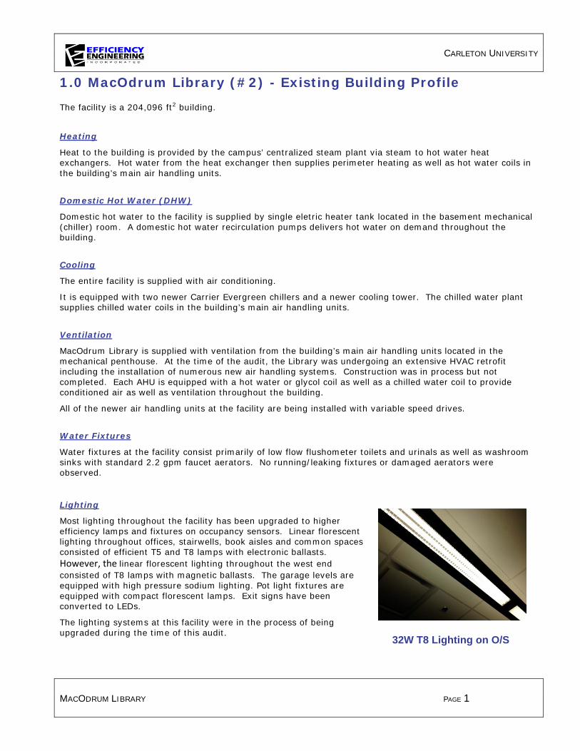
CARLETON UNIVERSITY
MACODRUM LIBRARY PAGE 1
1.0 MacOdrum Library (#2) - Existing Building Profile
The facility is a 204,096 ft2 building.
Heating
Heat to the building is provided by the campus’ centralized steam plant via steam to hot water heat exchangers. Hot water from the heat exchanger then supplies perimeter heating as well as hot water coils in the building’s main air handling units.
Domestic Hot Water (DHW)
Domestic hot water to the facility is supplied by single eletric heater tank located in the basement mechanical (chiller) room. A domestic hot water recirculation pumps delivers hot water on demand throughout the building.
Cooling
The entire facility is supplied with air conditioning.
It is equipped with two newer Carrier Evergreen chillers and a newer cooling tower. The chilled water plant supplies chilled water coils in the building’s main air handling units.
Ventilation
MacOdrum Library is supplied with ventilation from the building’s main air handling units located in the mechanical penthouse. At the time of the audit, the Library was undergoing an extensive HVAC retrofit including the installation of numerous new air handling systems. Construction was in process but not completed. Each AHU is equipped with a hot water or glycol coil as well as a chilled water coil to provide conditioned air as well as ventilation throughout the building.
All of the newer air handling units at the facility are being installed with variable speed drives.
Water Fixtures
Water fixtures at the facility consist primarily of low flow flushometer toilets and urinals as well as washroom sinks with standard 2.2 gpm faucet aerators. No running/leaking fixtures or damaged aerators were observed.
Lighting
Most lighting throughout the facility has been upgraded to higher efficiency lamps and fixtures on occupancy sensors. Linear florescent lighting throughout offices, stairwells, book aisles and common spaces consisted of efficient T5 and T8 lamps with electronic ballasts. However, the linear florescent lighting throughout the west end consisted of T8 lamps with magnetic ballasts. The garage levels are equipped with high pressure sodium lighting. Pot light fixtures are equipped with compact florescent lamps. Exit signs have been converted to LEDs.
The lighting systems at this facility were in the process of being upgraded during the time of this audit.
32W T8 Lighting on O/S

CARLETON UNIVERSITY
MACODRUM LIBRARY PAGE 2
2.0 Energy Savings Scenario
The Energy Savings Scenario consists of all Opportunities that are recommended based primarily on the energy and utility cost saving benefits.
M01 – Lighting Upgrade: Replace Magnetic Ballasts in West End
M01.1 - Existing Conditions
The west end of this facility is illuminated by 32 watt T8 lamps with magnetic ballasts in linear fluorescent fixtures. However, the lighting systems at this facility were in the process of being upgraded during the time of this audit.
M01.2 - Retrofit Conditions
We recommend retrofitting existing fixtures housing magnetic ballasts with reduced wattage (25w) lamps and high efficiency electronic ballasts. A high performance retrofit achieves 37% savings over the existing T8 system and 49% savings over the existing T12 system.
July 1, 2010 saw the ban of magnetic ballast production in Canada. This includes the large majority of T12 and T8 magnetic ballasts. This means that when a magnetic ballast fails it must be replaced with an electronic ballast. There are many benefits to changing to electronic ballasts, well beyond the improved efficiency. Total Harmonic Distortion (THD) is greatly reduced. The “flicker” and “hum” that magnetic systems are notoriously known for are greatly reduced. Electronic ballasts have longer average life spans, improve lamp life and because they can drive up to 4 lamps versus just 1 or 2 lamps, and they create less waste.
M02 – Combination photocell/occupancy sensor for new area currently under construction
M02.1 - Existing Conditions
The windows on the west end of this facility provide high levels of natural daylight. Lighting controls seemed to be in the process of being updated during the audit to occupancy sensors throughout the west end.
M02.2 - Retrofit Conditions
We recommend installing photocells to control the perimeter lighting in the west end of the facility.
Photocells turn lights “off” when natural daylight levels are sufficient to meet light level requirements for the space and “on” when daylighting levels fall below set threshold. Photocells used in combination with dimmable ballasts have the ability to slowly dim lighting level in accordance with natural daylighting levels entering the space. Many sensors allow “sensitivity” or “lighting thresholds’ to be adjusted to accommodate certain tasks and areas.
In general, we recommend installing occupancy sensors in any offices, common areas and corridors that has not yet been upgraded. It is important that qualified contractors are familiar with all building code and by law requirements regarding the installation of occupancy sensors, lighting level requirements and fire code. Safety of occupants should always be addressed when determining suitable applications for occupancy sensors.
M05 – Implement “Partial Occupancy” Schedule – AHU’s
M05.1 - Existing Conditions
Ventilation to the building is provided by numerous recirculatory mixing air handling units. These units
CARLETON UNIVERSITY
MACODRUM LIBRARY PAGE 3
bring in fixed amounts of outdoor air and blend it with return air before returning it to the space. Any outdoor air brought into the building must be heated or cooled by the building’s HVAC systems, so it’s best to minimize it.
The AHU’s bring in a variable amount of outdoor air based on outdoor and supply air temperatures. The minimum amount of outdoor air being brought in by a particular AHU is controlled by the minimum outdoor air damper position set at the BAS. Typically, the minimum ventilation level (minimum outdoor air damper position), would be set to provide adequate ventilation during times of peak occupancy (fully occupied hours). Any outside air brought into the building has to be conditioned by heating or cooling equipment, so it is best to minimize it.
Currently, the air handling units operate seven days per week, 365 days per year. They typically operate from 7 in the morning through until 10 at night with slightly reduced hours on weekends. During these hours of operation, the units are bringing in ventilation air at a rate based on the minimum outdoor air damper position (15-25%). This minimum ventilation rate is typically based on the expected normal peak occupancy of the building.
The building is primarily used as a library with office space with peak occupancy occurring during normal business hours, Monday-Friday from 8am to 5pm. Occupancy during early morning, late evening and weekend periods is drastically lower. Currently, however, the AHU’s continue to bring in large amounts of ventilation air during these times of “partial occupancy”.
M05.2 - Retrofit Conditions
We recommend implementing a “Partial Occupancy” schedule to reduce the amount of fresh air supplied during times of lower occupancy (evenings, weekends, during extended breaks). The existing Occupied/Unoccupied schedule for the AHU’s will be updated to include a “Partial Occupancy” schedule at the beginning and end of each day as well as over weekends and during summer and winter breaks as appropriate. During the scheduled “Partial Occupancy” hours, the minimum outdoor air damper position will be reset to a lower value than the current “occupied hours” minimum to reflect the greatly reduced occupancy loads. This will reduce unnecessary amounts of outdoor air needing to be conditioned. Implementation costs for this measure are relatively low for the scheduling. As all of the controls exist, only updating of the building automation system would be required.
M06 – Water Conservation: Ultra Low Flow Aerators
M06.1 - Existing Conditions
All of the toilets and urinals throughout the building are low flow fixtures. The sinks located throughout the building have standard (2.2 gpm) aerators installed.
M06.2 - Retrofit Conditions
We recommend installing ultra low flow, 0.5 GPM, aerators on all faucets to further reduce water consumption.
M07 – Campus Wide Integrated Lighting Controls
M07.1 - Existing Conditions
Many of the building’s offices, classrooms and lecture halls are being controlled by local wall switches. In many cases lights remain on longer than the space is occupied.
M07.2 - Retrofit Conditions
An efficient integrated lighting control system should take advantage of savings through time scheduling, daylight harvesting, task tuning, occupancy control, personal control and variable load shedding. Combined effectively, these methods can result in 50-75% energy savings.

CARLETON UNIVERSITY
MACODRUM LIBRARY PAGE 4
To achieve maximal energy savings an effective integrated lighting control system should provide: • a user friendly interface that would allow on site staff to control lighting throughout the entire
facility or campus using a point and click set up (interface can be on a network PC system or web-based for ultimate control for future portfolio monitoring and control)
• the ability to adjust settings, limits, and time schedules on event specific, daily, weekly, or monthly basis
• allow for interface with HVAC and Security control systems and equipment to share data such as occupancy status and adjust for status. This type of system would allow individuals to immediately identify which areas of a building or campus are occupied at what hours, providing additional information to security personnel.
• allow monitoring of occupancy sensors, dimmers and wall switches to enable zones to be configured such that only the fixtures in that entrance and exit pathway or area shall be left on.
• allow for personal settings to be adjusted and set for specific fixtures or group of fixtures. This can increase productivity as it ensures that individuals can select the amount of light that best enables them to perform a task.
• the ability to illustrate and report consumption, light levels, light status, power density, and occupancy status help ensure that the system is being effectively utilized while also having the added benefit of simple assurance that all individuals have vacated the facility.
We recommend that a high performance integrated lighting control system meeting the above criteria be installed campus wide.
As electrical rates and time of use charges increase, it is becoming more critical that energy savings are achieved not only by installing efficient lighting but by controlling the way and time of use lighting is utilized.
3.0 Longer Payback Scenario
The Longer Payback Scenario consists of Opportunities that are not as financially attractive as the Energy Savings Scenario. These measures should be considered when equipment failure occurs or as Capital Renewal projects as equipment reaches its end of life.
M03 – Domestic Hot Water Conversion: Electric To Steam
M03.1 - Existing Conditions
MacOdrum Library is supplied with domestic hot water from an electric heater tank located in the basement mechanical (chiller) room. Electricity, though efficient, is an expensive heat source. Steam is currently available within the basement mechanical room where the heater tank is located. The nearby steam piping should be taken advantage of as it has the capacity to heat the DHW at a lower cost than electricity.
M03.2 - Retrofit Conditions
We recommend replacing the existing electric heater tank with a DHW system supplied by the central steam plant. The existing heater tank should be replaced with a heat exchanger and domestic hot water storage tank.

CARLETON UNIVERSITY
MACODRUM LIBRARY PAGE 5
M04 – Commission New Mechanical Room when Complete
M04.1 - Existing Conditions
MacOdrum Library was in the process of an extensive HVAC retrofit at the time of the audit. This retrofit included replacement of numerous air handling units, hot and chilled water pumps, exhaust fans etc. As equipment was in the process of being replaced, it’s operation and control strategies could not be verified or confirmed.
The original design of most buildings involves many assumptions about occupancy, internal heat gains, lighting loads, building envelope performance, etc. As a result, design engineers make conservative assumptions and design for extreme conditions. Little thought is put into part-load efficiency.
Building commissioning focuses on occupancy comfort with little regard for energy consumption. Also, commissioning takes place at the end of a project, and often is neglected due to project delays, cost overruns, reduced budgets, etc.
M04.2 - Retrofit Conditions
We recommend a complete, independent commissioning of MacOdrum Library once renovations have been completed. Commissioning, especially of the HVAC systems should focus on energy conservation while improving occupancy comfort.
Commissioning generally consists of:
Step 1 – Develop plan and form project team.
Step 2 – Develop performance baseline.
Step 3 – Conduct system measurements and develop processed measures
Step 4 – Implement measures.
Step 5 – Document comfort improvements and energy savings.
Step 6 – Keep the commissioning continuous.

CARLETON UNIVERSITY
UNIVERSITY CENTRE PAGE 1
1.0 University Centre (#7) – Existing Building Profile
The facility is a 127,581 ft2 building containing office spaces, classrooms, a student cafeteria, a full service restaurant and a bookstore.
Heating
Heat to the building is provided by the campus’ centralized steam plant via steam to hot water heat exchangers. Hot water from the heat exchanger then supplies perimeter heating as well as hot water coils in the building’s main air handling units. Packaged rooftop units also supply heating with natural gas burners.
Domestic Hot Water (DHW)
Domestic hot water to the facility is supplied by the campus’ central steam heating plant via an immersion steam to hot water heat exchanger located within the DHW storage tank. A domestic hot water recirculation pump delivers hot water on demand throughout the building.
Cooling
The entire facility is supplied with air conditioning.
It is equipped with its own chiller as well as a cooling tower which is in good operating condition. The chilled water plant supplies chilled water coils in the building’s main air handling units.
Ventilation
University Centre is supplied with ventilation from the building’s main air handling units located in the mechanical penthouse as well as packaged rooftop units. Each AHU is equipped with a hot water or glycol coil and a chilled water coil to provide conditioned air as well as ventilation throughout the building.
Most of the larger air handling units are equipped with variable speed drives. Some smaller units are not.
Water Fixtures
Water fixtures at the facility consist primarily of low flow flushometer toilets, urinals and showers as well as washroom sinks with aerators. No running/leaking fixtures or damaged aerators were observed.
Lighting
Most lighting throughout the facility has been upgraded to higher efficiency lamps and fixtures. Linear florescent lighting throughout offices, classrooms, corridors, stairwells and common spaces consisted of efficient 32W T8 lamps with electronic ballasts. A large portion of this facility consists of pot light fixtures equipped with compact florescent lamps. Exit signs have been converted to LED’s. The majority of lighting is controlled by local wall switch.
• 2.0 Energy Savings Scenario
The Energy Savings Scenario consists of all Opportunities that are recommended based primarily on the energy and utility cost saving benefits.
M01 – Lighting Controls: Occupancy Sensors
M01.1 - Existing Conditions
Lighting is primarily controlled by local wall switch. Many lights are left on when rooms remain

CARLETON UNIVERSITY
UNIVERSITY CENTRE PAGE 2
unoccupied. Corridors are typically left on 24/7. This is a high traffic facility that would greatly benefit from the use of occupancy sensors.
M01.2 - Retrofit Conditions
We recommend installing occupancy sensors in many of the offices, classrooms, corridors, and storage rooms. Typical energy savings range from 30%-60%, depending on the pattern and frequency of room use. It is important that qualified contractors are familiar with all building code and by law requirements regarding the installation of occupancy sensors, lighting level requirements and fire code. Safety of occupants should always be addressed when determining suitable applications for occupancy sensors.
M02 – Install Photocells in Areas of High Natural Light
M02.1 - Existing Conditions
The main entrance and stairwell up to the cafeteria provide high levels of natural daylight.
M02.2 - Retrofit Conditions
We recommend installing photocells to control the lighting in the main entrance area as well as the stairwell up to the cafeteria.
Photocells turn lights “off” when natural daylight levels are sufficient to meet light level requirements for the space and “on” when day lighting levels fall below set threshold. Photocells used in combination with dimmable ballasts have the ability to slowly dim lighting level in accordance with natural day lighting levels entering the space. Many sensors allow “sensitivity” or “lighting thresholds’ to be adjusted to accommodate certain tasks and areas.
M03 – Water Conservation: Ultra Low Flow Aerators
M03.1 - Existing Conditions
The majority of washroom sinks located throughout the building are equipped with standard low flow (2.2 gpm) aerators.
M03.2 - Retrofit Conditions
We recommend installing ultra low flow, 0.5 GPM, aerators on all washroom faucets to further reduce water consumption.
M04 – Install VFD’s on AHU-1 (Main Lobby Eng Air Unit), AHU-2 (Bookstore), AHU-3 Supply Fans (Cafeteria), AHU-5 (Galleria), AHU-6 (Galleria)
M04.1 - Existing Conditions
All of the buildings AHU’s are mixed air units which bring in controlled amounts of ventilation air and blend it with return air before delivering it to specific areas of the facility. Each of the AHU’s is equipped with a hot water coil or a natural gas burner for heating as well as a chilled water coil for cooling.
The fans for each of these AHU’s is sized to supply adequate air flows during times of peak heating,

CARLETON UNIVERSITY
UNIVERSITY CENTRE PAGE 3
cooling or ventilation load requirements. Some of the AHU’s are currently equipped with VFD’s or variable inlet vanes to reduce air flows during off peak times. Several of the AHU’s, however, lack any type of air flow control.
M04.2 - Retrofit Conditions
We recommend installing variable frequency drives (VFD’s) and inverter duty motors on the supply and return fans of AHU-1, -2, -3, -5 and -6. Fan speeds will modulate to maintain space temperature set points in each zone of the air handling unit. As a space calls for heating, the heating control valve for the reheat coil will open. If space temperature cannot be maintained once the reheat coil has reached 100%, the fan speed will ramp up to provide more heat to the space.
M05 – Implement Demand Control Ventilation on AHU-1 (Main Lobby Eng Air Unit), AHU-2 (Bookstore), AHU-3 (Cafeteria), AHU-4 (Classrooms), AHU-5 (Galleria), AHU-6 (Galleria), AHU-7 (Unicentre Pub), UniCentre Mez 3rd Floor (Fans 607/608), AHU-Porter Hall (Fans 605/606), AHU-Penthouse VV (Fans 609, 610), AHU-UniMez South (Fans 301/302)
M05.1 - Existing Conditions
The air-handling units provide heating, cooling and ventilation to the entire facility, blending fresh air and return air to a fixed mixed air temperature setpoint. This provides temperature and humidity control in the space, but tends to bring in more ventilation air than needed, especially during partial occupancy periods. Any outside air brought into the building has to be conditioned by heating or cooling equipment, so it is best to minimize it.
M05.2 - Retrofit Conditions
CO2 control on the air handlers would ensure that ventilation air volumes are matched to occupancy under all conditions. CO2 sensors would be installed in occupied areas and return air ducts, as appropriate for each air handler. ASHRAE Standard 62 recognizes that ambient (outdoor) CO2 levels can fluctuate, and that a better measure of ventilation requirements in the space is to use the difference between indoor and ambient levels. An outside sensor would also be installed to determine the ambient CO2 levels. The new sensors would be connected to the building automation system, which would be reprogrammed to maintain the indoor air CO2 levels at 700 ppm above ambient.
The outside air and relief dampers would be replaced with low leakage dampers.
M06 – Campus Wide Integrated Lighting Controls
M06.1 - Existing Conditions
Many of the building’s offices, classrooms and lecture halls are being controlled by local wall switches. In many cases lights remain on longer than the space is occupied.
M06.2 - Retrofit Conditions
An efficient integrated lighting control system should take advantage of savings through time scheduling, daylight harvesting, task tuning, occupancy control, personal control and variable load shedding. Combined effectively, these methods can result in 50-75% energy savings.
To achieve maximal energy savings an effective integrated lighting control system should provide: • a user friendly interface that would allow on site staff to control lighting throughout the entire

CARLETON UNIVERSITY
UNIVERSITY CENTRE PAGE 4
facility or campus using a point and click set up (interface can be on a network PC system or web-based for ultimate control for future portfolio monitoring and control)
• the ability to adjust settings, limits, and time schedules on event specific, daily, weekly, or monthly basis
• allow for interface with HVAC and Security control systems and equipment to share data such as occupancy status and adjust for status. This type of system would allow individuals to immediately identify which areas of a building or campus are occupied at what hours, providing additional information to security personnel.
• allow monitoring of occupancy sensors, dimmers and wall switches to enable zones to be configured such that only the fixtures in that entrance and exit pathway or area shall be left on.
• allow for personal settings to be adjusted and set for specific fixtures or group of fixtures. This can increase productivity as it ensures that individuals can select the amount of light that best enables them to perform a task.
• the ability to illustrate and report consumption, light levels, light status, power density, and occupancy status help ensure that the system is being effectively utilized while also having the added benefit of simple assurance that all individuals have vacated the facility.
We recommend that a high performance integrated lighting control system meeting the above criteria be installed campus wide.
As electrical rates and time of use charges increase, it is becoming more critical that energy savings are achieved not only by installing efficient lighting but by controlling the way and time of use lighting is utilized.

CARLETON UNIVERSITY
MACKENZIE BUILDING PAGE 1
1.0 Mackenzie Building (#10) - Existing Building Profile
The facility is a 188,020 ft2 building containing offices and classrooms.
Heating
Heat to the building is provided by the campus’ centralized steam plant via steam to hot water heat exchangers. Hot water from the heat exchanger then supplies perimeter heating as well as hot water reheat coils in the building’s supply air duct work. Each space is typically equipped with its own thermostat for temperature control.
Domestic Hot Water (DHW)
Domestic hot water to the facility is supplied by the campus’ central steam heating plant via a steam to hot water heat exchanger. A domestic hot water recirculation pump delivers hot water on demand throughout the building.
Cooling
The entire facility is supplied with air conditioning through chilled water coils in the main air handling units.
Chilled water is supplied by a chilled water plant located in another building. The remote chilled water plant is served by a cooling tower located on the rooftop of the MacKenzie building. The cooling tower is equipped with a variable speed drive.
Ventilation
The MacKenzie Building is supplied with ventilation from the building’s main air handling units located in various mechanical rooms throughout the building. Each AHU is equipped with a chilled water coil for cooling.
None of the air handling units are currently equipped with variable speed drives.
Water Fixtures
Water fixtures at the facility consist primarily of low flow flushometer toilets and urinals as well as washroom sinks with aerators. No running/leaking fixtures or damaged aerators were observed.
Lighting Most lighting throughout the facility has been upgraded to higher efficiency
lamps and fixtures. Linear fluorescent lighting throughout offices, classrooms, corridors and common spaces consisted of efficient T8 lamps with electronic ballasts. Linear florescent lighting throughout stairwell spaces consisted of T8 lamps with magnetic ballasts. All mechanical rooms were equipped with occupancy sensor timer switches. Pot light fixtures were equipped with compact florescent lamps. Exit signs have been converted to LEDs. The majority of lighting is controlled by local wall switch.
2.0 Energy Savings Scenario
The Energy Savings Scenario consists of all Opportunities that are recommended based primarily on the energy and utility cost saving benefits.
Washroom sink with low flow

CARLETON UNIVERSITY
MACKENZIE BUILDING PAGE 2
M01 – Lighting Upgrade: High Performance T8 Retrofit
M01.1 - Existing Conditions
The linear fluorescent fixtures in the stairwells at this building house 32 watt T8 lamps and inefficient magnetic ballasts. Some ballasts have been updated to electronic ballasts as they fail.
M01.2 - Retrofit Conditions
We recommend retrofitting existing 4ft T8 fixtures with reduced wattage (25w) lamps and high efficiency electronic ballasts. A high performance retrofit achieves 37% savings over the existing system.
July 1, 2010 saw the ban of magnetic ballast production in Canada. This includes the large majority of T12 and T8 magnetic ballasts. This means that when a magnetic ballast fails it must be replaced with an electronic ballast. There are many benefits to changing to electronic ballasts, well beyond the improved efficiency. Total Harmonic Distortion (THD) is greatly reduced. The “flicker” and “hum” that magnetic systems are notoriously known for are greatly reduced. Electronic ballasts have longer average life spans, improve lamp life and because they can drive up to 4 lamps versus just 1 or 2 lamps, and they create less waste.
M02 – Lighting Controls: Install Occupancy Sensors
M02.1 - Existing Conditions
Many of the building’s offices, classrooms and washrooms are being controlled by local wall switches. In many cases lights remain on longer than the space is occupied.
M02.2 - Retrofit Conditions
We recommend installing occupancy sensors in many of the offices, classrooms, corridors, and storage rooms. Typical energy savings range from 30%-60%, depending on the pattern and frequency of room use. It is important that qualified contractors are familiar with all building code and by law requirements regarding the installation of occupancy sensors, lighting level requirements and fire code. Safety of occupants should always be addressed when determining suitable applications for occupancy sensors.
M03 – Water Conservation: Ultra Low Flow Aerators
M03.1 - Existing Conditions
All of the toilets and urinals throughout the building are low flow fixtures. The sinks located throughout the building have standard (2.2 gpm) aerators installed.
M03.2 - Retrofit Conditions
We recommend installing ultra low flow, 0.5 GPM, aerators on all faucets to further reduce water consumption.
M05 – Install VFD’s on AHU’s and Reset to Outdoor Air Temperature
M05.1 - Existing Conditions
All of the buildings AHU’s are mixed air units which bring in controlled amounts of ventilation air and

CARLETON UNIVERSITY
MACKENZIE BUILDING PAGE 3
blend it with return air before delivering it to specific areas of the facility. Each of the AHU’s is equipped with a chilled water coil which provides cooling. All of the AHU’s are also equipped with terminal re-heat coils (hot water) located in the duct work which allows each individual room supplied by the air handling unit to have independent temperature control.
The fans for each of these AHU’s is sized to supply adequate air flows during times of peak heating, cooling or ventilation load requirements.
M05.2 - Retrofit Conditions
We recommend installing variable frequency drives (VFD’s) and inverter duty motors on the supply and return fans of the AHU’s. Fan speeds will modulate to maintain space temperature set points in each zone of the air handling unit. As a space calls for heating, the heating control valve for the reheat coil will open. If space temperature cannot be maintained once the reheat coil has reached 100%, the fan speed will ramp up to provide more heat to the space.
M06 – Implement “Partial Occupancy” Schedule – AHU’s-2, -3, 10D-112, -3, -4, -5, -6, -9, -10, -11
M06.1 - Existing Conditions
Ventilation to the building is provided by several mixed air handling units. These units bring in fixed amounts of outdoor air and blend it with return air before returning it to the space. Any outdoor air brought into the building must be heated or cooled by the building’s HVAC systems, so it’s best to minimize it.
The AHU’s bring in a variable amount of outdoor air based on outdoor and supply air temperatures. The minimum amount of outdoor air being brought in by a particular AHU is controlled by the minimum outdoor air damper position set at the BAS. Typically, the minimum ventilation level (minimum outdoor air damper position), would be set to provide adequate ventilation during times of peak occupancy (fully occupied hours). Any outside air brought into the building has to be conditioned by heating or cooling equipment, so it is best to minimize it.
Currently, the air handling units operate seven days per week, 365 days per year. They typically operate from 7 in the morning through until 10 at night with slightly reduced hours on weekends. During these hours of operation, the units are bringing in ventilation air at a rate based on the minimum outdoor air damper position (15%). This minimum ventilation rate is typically based on the expected normal peak occupancy of the building.
The building is primarily used as classroom and office space with peak occupancy occurring during normal business hours, Monday-Friday from 8am to 5pm. Occupancy during early morning, late evening and weekend periods is drastically lower. Currently, however, the AHU’s continue to bring in large amounts of ventilation air during these times of “partial occupancy”.
M06.2 - Retrofit Conditions
We recommend implementing a “Partial Occupancy” schedule to reduce the amount of fresh air supplied during times of lower occupancy (evenings, weekends, during extended breaks). The existing Occupied/Unoccupied schedule for the AHU’s will be updated to include a “Partial Occupancy” schedule at the beginning and end of each day as well as over weekends and during summer and winter breaks as appropriate. During the scheduled “Partial Occupancy” hours, the minimum outdoor air damper position will be reset to a lower value than the current occupied hours minimum to reflect the greatly reduced occupancy loads. This will reduce unnecessary amounts of outdoor air needing to be conditioned. Implementation costs for this measure are relatively low for the scheduling. As all of the controls exist, only updating of the building automation system would be required.
CARLETON UNIVERSITY
MACKENZIE BUILDING PAGE 4
M07 – Campus Wide Integrated Lighting Controls
M07.1 - Existing Conditions
Many of the building’s offices, classrooms and lecture halls are being controlled by local wall switches. In many cases lights remain on longer than the space is occupied.
M07.2 - Retrofit Conditions
An efficient integrated lighting control system should take advantage of savings through time scheduling, daylight harvesting, task tuning, occupancy control, personal control and variable load shedding. Combined effectively, these methods can result in 50-75% energy savings.
To achieve maximal energy savings an effective integrated lighting control system should provide: • a user friendly interface that would allow on site staff to control lighting throughout the entire
facility or campus using a point and click set up (interface can be on a network PC system or web-based for ultimate control for future portfolio monitoring and control)
• the ability to adjust settings, limits, and time schedules on event specific, daily, weekly, or monthly basis
• allow for interface with HVAC and Security control systems and equipment to share data such as occupancy status and adjust for status. This type of system would allow individuals to immediately identify which areas of a building or campus are occupied at what hours, providing additional information to security personnel.
• allow monitoring of occupancy sensors, dimmers and wall switches to enable zones to be configured such that only the fixtures in that entrance and exit pathway or area shall be left on.
• allow for personal settings to be adjusted and set for specific fixtures or group of fixtures. This can increase productivity as it ensures that individuals can select the amount of light that best enables them to perform a task.
• the ability to illustrate and report consumption, light levels, light status, power density, and occupancy status help ensure that the system is being effectively utilized while also having the added benefit of simple assurance that all individuals have vacated the facility.
We recommend that a high performance integrated lighting control system meeting the above criteria be installed campus wide.
As electrical rates and time of use charges increase, it is becoming more critical that energy savings are achieved not only by installing efficient lighting but by controlling the way and time of use lighting is utilized.
3.0 Longer Payback Scenario
The Longer Payback Scenario consists of Opportunities that are not as financially attractive as the Energy Savings Scenario. These measures should be considered when equipment failure occurs or as Capital Renewal projects as equipment reaches its end of life.
M04 – Replace Current Single Pane Windows
M04.1 - Existing Conditions
There are single pane windows in several areas of the facility. Glass has very little thermal resistance, so the windows represent a major area of heat loss in winter and heat gain in summer. In addition, the existing frames and operable sections are leaky, so there is significant air infiltration around them.

CARLETON UNIVERSITY
MACKENZIE BUILDING PAGE 5
M04.2 - Retrofit Conditions
It is recommended that the single pane windows be replaced with double pane thermally broken aluminum frame windows. Existing operable windows should b e replaced with operable windows. Newer windows will have a higher R-value (better insulating characteristics), and will also have tighter frames resulting in less infiltration. Specify argon-filled windows with a low-emissivity interior coating to block some of the summer radiant heat gain and to reduce color fading of furniture or carpets.

CARLETON UNIVERSITY
MAINTENANCE BUILDING PAGE 1
1.0 Maintenance Building (#11) - Existing Building Profile
The facility is a 43,815 ft2, 2 storey building which serves primarily as offices as well as some maintenance shop areas.
Heating
Heat to the building is provided to the building from various heat sources including multiple air handling units (using heat from the campus’ centralized steam plant), electric resistance coils, and several rooftop units equipped with gas fired furnaces.
Domestic Hot Water (DHW)
Domestic hot water to the facility is supplied by an instantaneous heat exchanger which draws from the University’s centralized steam plant. A DHW recirculation pump distributes hot water throughout the building.
Cooling
The entire facility is supplied with air conditioning.
The building is equipped with multiple rooftop air handling units which have their own direct expansion cooling as well as air handling units which are supplied by a chilled water loop.
Ventilation
The Maintenance building is supplied with ventilation from the building’s multiple air handling units located in mechanical rooms and across the roof. Each AHU is equipped with a heating coil. Some units are equipped with cooling coils. The majority of the air handling units are constant volume with recirculatory mixing ventilation.
All systems are monitored by the BAS and are programmed to a schedule according to occupancy.
Water Fixtures
Water fixtures at the facility consist of low flow flushometer toilets and kitchen and washroom sinks with aerators. No running/leaking fixtures or damaged aerators were observed.
Lighting
Lighting is a mixture of T12 and T8 linear fluorescent lamps with magnetic ballasts. The new addition is primarily illuminated by 32 watt T8 lamps with electronic ballasts. The large majority of exit signs are LED with a few incandescent exit signs still remaining in the front entrance corridor. The boiler plant houses high pressure sodium highbay fixtures. Lighting is controlled by local wall switch.
Exterior lighting is high pressure sodium wall packs and recessed pot lights.
DHW Heat Exchanger
Typical Washroom Sink

CARLETON UNIVERSITY
MAINTENANCE BUILDING PAGE 2
2.0 Energy Savings Scenario
The Energy Savings Scenario consists of all Opportunities that are recommended based primarily on the energy and utility cost saving benefits.
M01 – Install Steam Control Valve on DHW-1
M01.1 - Existing Conditions
This facility has a domestic hot water loop which is fed from the University’s centralized steam loop. The DHW heat exchanger currently has steam passing through it constantly, regardless of the heating demand of the hot water.
M01.2 - Retrofit Conditions
We recommend that a two way steam control valve be installed to control the flow of the steam based on the temperature of the DHW loop. This allows the heat output of the heat exchanger to more closely match the actual DHW heating demand.
M03 – Implement “Partial Occupancy” Schedule – All AHU’s
M03.1 - Existing Conditions
Ventilation to the building is provided by several mixed air handling units. These units bring in fixed amounts of outdoor air and blend it with return air before returning it to the space. Any outdoor air brought into the building must be heated or cooled by the building’s HVAC systems, so it’s best to minimize it. The AHU’s bring in a variable amount of outdoor air based on outdoor and supply air temperatures. The minimum amount of outdoor air being brought in by a particular AHU is controlled by the minimum outdoor air damper position set at the BAS. Typically, the minimum ventilation level (minimum outdoor air damper position), would be set to provide adequate ventilation during times of peak occupancy (fully occupied hours). Any outside air brought into the building has to be conditioned by heating or cooling equipment, so it is best to minimize it. Currently, the air handling units operate seven days per week, 365 days per year. They typically operate from 5-7 in the morning through until 5-7 at night with slightly reduced hours on weekends. During these hours of operation, the units are bringing in ventilation air at a rate based on the minimum outdoor air damper position (10-25%). This minimum ventilation rate is typically based on the expected normal peak occupancy of the building. The building is primarily used as office space with peak occupancy occurring during normal business hours, Monday-Friday from 8am to 5pm. Occupancy during early morning, late evening and weekend periods is drastically lower. Currently, however, the AHU’s continue to bring in large amounts of ventilation air during these times of “partial occupancy”.
M03.2 - Retrofit Conditions
We recommend implementing a “Partial Occupancy” schedule to reduce the amount of fresh air supplied during times of lower occupancy (evenings, weekends, during extended breaks). The existing Occupied/Unoccupied schedule for the AHU’s will be updated to include a “Partial Occupancy” schedule at the beginning and end of each day as well as over weekends and during summer and winter breaks as appropriate. During the scheduled “Partial Occupancy” hours, the minimum outdoor air damper position will be reset to a lower value than the current occupied hours minimum to reflect the greatly reduced occupancy loads. This will reduce unnecessary amounts of outdoor air needing to be conditioned. Implementation costs for this measure are relatively low for the scheduling. As all of the

CARLETON UNIVERSITY
MAINTENANCE BUILDING PAGE 3
controls exist, only updating of the building automation system would be required.
M04 – Optimal start/stop of RTU-U1-Admin
M04.1 - Existing Conditions
The building has a rooftop unit which heats and cools the administration area. The current BAS schedule for this unit is longer than the occupied hours of the area.
M04.2 - Retrofit Conditions
Operating HVAC units for longer hours than necessary consumes excess electrical energy to run the fans. Additionally, these units bring in ventilation air which must be heated or cooled to the supply air temperature before being delivered to the space. We recommended that the schedule be updated to serve the current occupied hours within the space.
M05 – Lighting Upgrade: High Performance T8 Retrofit
M05.1 - Existing Conditions
Linear fluorescent fixtures throughout the building house a mixture of T12 and T8 lamps in combination with inefficient magnetic ballasts. As the magnetic ballasts sporadically fail they are being replaced with electronic ballasts.
M05.2 - Retrofit Conditions
We recommend retrofitting existing fixtures housing magnetic ballasts with reduced wattage (25w) lamps and high efficiency electronic ballasts. A high performance retrofit achieves 37% savings over the existing T8 system and 49% savings over the existing T12 system.
July 1, 2010 saw the ban of magnetic ballast production in Canada. This includes the large majority of T12 and T8 magnetic ballasts. This means that when a magnetic ballast fails it must be replaced with an electronic ballast. There are many benefits to changing to electronic ballasts, well beyond the improved efficiency. Total Harmonic Distortion (THD) is greatly reduced. The “flicker” and “hum” that magnetic systems are notoriously known for are greatly reduced. Electronic ballasts have longer average life spans, improve lamp life and because they can drive up to 4 lamps versus just 1 or 2 lamps, and they create less waste.
M06- Lighting Upgrades: LED Exit Signs
M06.1 - Existing Conditions
A number of exit signs still house incandescent lamps which roughly consume 30-50 watts per fixtures.
M06.2 - Retrofit Conditions
We recommend replacing all incandescent exit signs with LED exit signs that consume less than 5 watts per unit.
M07– Lighting Upgrade: T5 High Output Lighting
M07.1 - Existing Conditions
The boiler room is illuminated by high pressure sodium (HPS) high bay fixtures and T12 & T8 strip lighting. The high bay fixtures remain on 24/7.

CARLETON UNIVERSITY
MAINTENANCE BUILDING PAGE 4
M07.2 - Retrofit Conditions
We recommend replacing the HPS high bay fixtures with T5 high output lighting. T5HO lighting creates up front energy savings by reducing consumption. Average lamp life of T5HO lamp is slightly greater than that of HPS; 30,000 -36,000 hrs vs 24,000 hrs and T5HO lamps also have exceptional lumen maintenance of 95%. Additional benefits lay in T5HO lighting’s ability to instantly turn off and on with no re-strike time. T5HO lighting works exceptionally well with occupancy sensors, creating further savings.
M08 – Lighting Controls: Install Occupancy Sensors
M08.1 - Existing Conditions
Lighting is primarily controlled by local wall switch. Many lights are left on when rooms remain unoccupied. Corridors and Boiler Room are typically left on 24/7.
M08.2 - Retrofit Conditions
We recommend installing occupancy sensors in many of the offices, corridors, washrooms and storage rooms. Typical energy savings range from 30%-60%, depending on the pattern and frequency of room use. It is important that qualified contractors are familiar with all building code and by law requirements regarding the installation of occupancy sensors, lighting level requirements and fire code. Safety of occupants should always be addressed when determining suitable applications for occupancy sensors.
M09 – Water Conservation: Install Ultra Low Flow 0.5 gpm Faucet Aerators
M09.1 - Existing Conditions
Water faucets throughout the building are currently equipped with standard 2.2 gallon per minute (gpm) aerators in the washrooms.
M09.2 - Retrofit Conditions
We recommend installing ultra low flow faucet aerators on all existing faucets with 2.2 gpm aerators. These ultra low flow aerators supply hand sanitation at a much lower flow rate at 0.5 gpm.
M10 – Campus Wide Integrated Lighting Controls
M10.1 - Existing Conditions
Lighting is primarily controlled by local wall switch. Many lights are left on when areas remain unoccupied or in areas where adequate natural light is illuminating the area. Corridors are typically left on 24/7.
M10.2 - Retrofit Conditions
An efficient integrated lighting control system should take advantage of savings through time scheduling, daylight harvesting, task tuning, occupancy control, personal control and variable load shedding. Combined effectively, these methods can result in 50-75% energy savings.
To achieve maximal energy savings an effective integrated lighting control system should provide: • a user friendly interface that would allow on site staff to control lighting throughout the entire
facility or campus using a point and click set up (interface can be on a network PC system or web-based for ultimate control for future portfolio monitoring and control)
CARLETON UNIVERSITY
MAINTENANCE BUILDING PAGE 5
• the ability to adjust settings, limits, and time schedules on event specific, daily, weekly, or monthly basis
• allow for interface with HVAC and Security control systems and equipment to share data such as occupancy status and adjust for status. This type of system would allow individuals to immediately identify which areas of a building or campus are occupied at what hours, providing additional information to security personnel.
• allow monitoring of occupancy sensors, dimmers and wall switches to enable zones to be configured such that only the fixtures in that entrance and exit pathway or area shall be left on.
• allow for personal settings to be adjusted and set for specific fixtures or group of fixtures. This can increase productivity as it ensures that individuals can select the amount of light that best enables them to perform a task.
• the ability to illustrate and report consumption, light levels, light status, power density, and occupancy status help ensure that the system is being effectively utilized while also having the added benefit of simple assurance that all individuals have vacated the facility.
We recommend that a high performance integrated lighting control system meeting the above criteria be installed campus wide.
As electrical rates and time of use charges increase, it is becoming more critical that energy savings are achieved not only by installing efficient lighting but by controlling the way and time of use lighting is utilized.
3.0 Longer Payback Scenario
The Longer Payback Scenario consists of Opportunities that are not as financially attractive as the Energy Savings Scenario. These measures should be considered when equipment failure occurs or as Capital Renewal projects as equipment reaches its end of life.
M02 – Install VFD’s on AHU-11A2 and 11A3
M02.1 - Existing Conditions
AHU-11A2 and 11A3 both supply multiple zones throughout the maintenance building and are currently scheduled by the BAS.
The fans for each of these AHU’s are sized to supply adequate air flows during times of peak heating, cooling or ventilation load requirements. AHU’s 11A2 and 11A3, lack any type of air flow control during off peak periods.
M02.2 - Retrofit Conditions
We recommend installing variable frequency drives (VFD’s) and inverter duty motors on the supply and return fans of AHU-11A2 and 11A3. Fan speeds will modulate to maintain space temperature set points in each zone of the air handling unit. As a space calls for heating, the heating control valve for the reheat coil will open. If space temperature cannot be maintained once the reheat coil has reached 100%, the fan speed will ramp up to provide more heat to the space.

CARLETON UNIVERSITY
STEACIE BUILDING PAGE 1
1.0 Steacie Building (#12) - Existing Building Profile
The facility is a 107,104 ft2, 5 storey building which serves primarily as laboratories and classrooms with some offices.
Heating
Heat to the building is provided to the building from the campus’ centralized steam plant. The steam is fed directly and through heat exchangers to multiple air handling unit heating coils to provide space heating and also feeds the perimeter heating throughout the building.
Domestic Hot Water (DHW)
Domestic hot water to the facility is supplied by an instantaneous heat exchanger which draws from the University’s centralized steam plant and is equipped with a recirculation loop and pump.
Cooling
The entire facility is supplied with air conditioning.
It is equipped with two large McQuay chillers and two Marley cooling towers. The chilled water plant serves the Steacie Building along with a few other buildings.
Ventilation
The Steacie Building is supplied with ventilation from the building’s multiple air handling units. Each AHU is equipped with heating and cooling coils. The majority of the air handling units are recirculatory mixing ventilation with the acception of AHU-2 which is 100% fresh air.
All systems are monitored by the BAS has a programmed schedule according to occupancy.
Water Fixtures
Water fixtures at the facility consist of low flow flushometer toilets and kitchen and washroom sinks with aerators. No running/leaking fixtures or damaged aerators were observed.
Lighting
Several areas of this facility have recently been renovated and new T5 fixtures have been installed. In areas where renovations have not taken place, the lighting primarily remains linear fluorescent 32 watt T8 lamps with inefficient magnetic ballasts. There are compact fluorescent pot lights and incandescent fixtures throughout the building. Exit signs are LED. Lighting is primarily controlled by local wall switch.
Exterior lighting is primarily pot light fixtures housing parabolic lamps. Exterior lighting is controlled by photocell.
2.0 Energy Savings Scenario
The Energy Savings Scenario consists of all Opportunities that are recommended based primarily on the energy and utility cost saving benefits.

CARLETON UNIVERSITY
STEACIE BUILDING PAGE 2
M01 –Implement Night Setback for AHU-17 and 18
M01.1 - Existing Conditions
AHU-17 and 18 currently supply to the east and west zones. They are re-circulatory mixing air handlers with a hot and cold deck (dual duct) for the capability of simultaneous heating and cooling to multiple zones. The supply and return fans are equipped with variable speed drives which are controlled by matching the speed of the building’s exhausts to maintain positive pressure. They are currently scheduled to run 24/7 on the BAS control.
M01.2 - Retrofit Conditions
We recommend optimizing the BAS controls by scheduling the AHU’s to maintain a lower temperature during unoccupied hours of the building. Implementing a night time reset temperature would allow the air handlers to consume less energy during unoccupied hours when there is no in the building to be comforted. The air handlers will maintain the lower temperatures during unoccupied periods, and then return to maintain the desired occupied temperature based on the schedule. Implementation costs for this measure are relatively low. As all of the controls exist, only updating of the building automation system would be required.
M02 – Re-commissioning
M02.1 - Existing Conditions
The Steacie building is currently operating with multiple labs and classrooms. All major HVAC equipment is currently monitored by the BAS, but most schedules are running the equipment for all hours of the day. There were some schedules which reduce the operating time of some equipment, but the schedules have the potential to be optimized further.
There is also the potential that some equipment be replaced with newer and more efficient equipment.
M02.2 - Retrofit Conditions
When older buildings which have only been commissioned since they were constructed, equipment tends to be neglected and starts operating inefficiently or incorrectly. Re-commissioning can save anywhere from 1% to 5% in energy savings through equipment optimization and operational corrections.
We recommend re-commissioning the Steacie building and its mechanical systems in order to optimize the equipment schedules and to find out if all equipment is operating the way it was originally designed to.
M04 – Insulate Steam and Hot Water Piping
M04.1 - Existing Conditions
The mechanical room was observed to have a high ratio of bare hot water piping. The piping for the radiator supply was exposed to the room’s environment. Bare hot water piping is always a potential for energy savings because it shows a great amount of heat loss potential.
Un-insulated Steam Piping

CARLETON UNIVERSITY
STEACIE BUILDING PAGE 3
M04.2 - Retrofit Conditions
During the winter months, the steam heat exchanger will supply a hot water loop which supplies the perimeter radiators with heat. The less heat that is lost before the hot water reaches the radiators, the more efficiently the system will operate.
We recommend insulating the radiator hot water piping in order to lower the amount of heat lost. The steam heat exchanger will therefore require less input to the radiator loop because of the lower piping heat loss.
M05 – Lighting Upgrade: High Performance T8 Retrofit
M05.1 - Existing Conditions
In areas where renovations have not taken place, the lighting primarily remains linear fluorescent 32 watt T8 lamps with inefficient magnetic ballasts.
M05.2 - Retrofit Conditions
For areas that are not scheduled for renovation in the near future, retrofitting the existing fixture is the most cost effective way to achieve significant savings.
We recommend retrofitting existing T8 fixtures with reduced wattage (25w) lamps and high efficiency electronic ballasts. A high performance retrofit achieves 37% savings over the existing system.
July 1, 2010 saw the ban of magnetic ballast production in Canada. This includes the large majority of T12 and T8 magnetic ballasts. This means that when a magnetic ballast fails it must be replaced with an electronic ballast. There are many benefits to changing to electronic ballasts, well beyond the improved efficiency. Total Harmonic Distortion (THD) is greatly reduced. The “flicker” and “hum” that magnetic systems are notoriously known for are greatly reduced. Electronic ballasts have longer average life spans, improve lamp life and because they can drive up to 4 lamps versus just 1 or 2 lamps, and they create less waste.
M06 – Lighting Upgrade: Incandescent to CFL
M06.1 - Existing Conditions
The fourth floor of the Steacie building still houses some incandescent lamps in recessed ceiling fixtures.
M06.2 - Retrofit Conditions
We recommend replacing all incandescent with compact fluorescent equivalents.
M07 – Lighting Controls: Install Occupancy Sensors
M07.1 - Existing Conditions
Lighting is primarily controlled by local wall switch. Many lights are left on when rooms remain unoccupied. Corridors are typically left on 24/7.
M07.2 - Retrofit Conditions
We recommend installing occupancy sensors in many of the offices, classrooms, corridors, and storage

CARLETON UNIVERSITY
STEACIE BUILDING PAGE 4
rooms. Typical energy savings range from 30%-60%, depending on the pattern and frequency of room use. It is important that qualified contractors are familiar with all building code and by law requirements regarding the installation of occupancy sensors, lighting level requirements and fire code. Safety of occupants should always be addressed when determining suitable applications for occupancy sensors.
M08 – Water Conservation: Install Ultra Low Flow 0.5 gpm Faucet Aerators
M08.1 - Existing Conditions
Water faucets throughout the building are currently equipped with 2.2 gallons per minute (gpm) aerators in the washrooms.
M08.2 - Retrofit Conditions
We recommend installing ultra low flow faucet aerators on all existing faucets with 2.2 gpm aerators. These ultra low flow aerators supply hand sanitation at a much lower flow rate at 0.5 gpm.
M09 – Campus Wide Integrated Lighting Controls
M09.1 - Existing Conditions
Lighting is primarily controlled by local wall switch. Many lights are left on when areas remain unoccupied or in areas where adequate natural light is illuminating the area. Corridors are typically left on 24/7.
M09.2 - Retrofit Conditions
An efficient integrated lighting control system should take advantage of savings through time scheduling, daylight harvesting, task tuning, occupancy control, personal control and variable load shedding. Combined effectively, these methods can result in 50-75% energy savings.
To achieve maximal energy savings an effective integrated lighting control system should provide: • a user friendly interface that would allow on site staff to control lighting throughout the entire
facility or campus using a point and click set up (interface can be on a network PC system or web-based for ultimate control for future portfolio monitoring and control)
• the ability to adjust settings, limits, and time schedules on event specific, daily, weekly, or monthly basis
• allow for interface with HVAC and Security control systems and equipment to share data such as occupancy status and adjust for status. This type of system would allow individuals to immediately identify which areas of a building or campus are occupied at what hours, providing additional information to security personnel.
• allow monitoring of occupancy sensors, dimmers and wall switches to enable zones to be configured such that only the fixtures in that entrance and exit pathway or area shall be left on.
• allow for personal settings to be adjusted and set for specific fixtures or group of fixtures. This can increase productivity as it ensures that individuals can select the amount of light that best enables them to perform a task.
• the ability to illustrate and report consumption, light levels, light status, power density, and occupancy status help ensure that the system is being effectively utilized while also having the added benefit of simple assurance that all individuals have vacated the facility.
We recommend that a high performance integrated lighting control system meeting the above criteria

CARLETON UNIVERSITY
STEACIE BUILDING PAGE 5
be installed campus wide.
As electrical rates and time of use charges increase, it is becoming more critical that energy savings are achieved not only by installing efficient lighting but by controlling the way and time of use lighting is utilized.
3.0 Longer Payback Scenario
The Longer Payback Scenario consists of Opportunities that are not as financially attractive as the Energy Savings Scenario. These measures should be considered when equipment failure occurs or as Capital Renewal projects as equipment reaches its end of life.
M03 – Install VAV Boxes
M03.1 - Existing Conditions
The supply air for the Steacie building is currently guided through a hot and cold deck system. This allows different zones to have different supply temperatures (different set points, heat gains, occupants, etc.). There is currently no control over the volume of air supplied to each zone.
M03.2 - Retrofit Conditions
If variable air volume (VAV) boxes are installed, the air handler supply and return fans can be controlled based on static pressure inside the ducts. The VAV box begins to close because the zone is at the desired temperature, and less air is required.
Reducing the amount of air supplied to each zone reduces energy consumption in a couple ways. It reduces the amount of energy needed to condition the smaller volume of air. The supply and return fans would be controlled to maintain a static pressure level, and when the VAV boxes close, it makes it easier to maintain this pressure level. This allows the fans to lower their speed and electrical consumption due to the lower level of air required to maintain the duct pressure.
By installing the VAV boxes and controlling the fans based on static duct pressure, less heating, cooling, and electrical energy can offer a reduction in total energy consumption of this building.

CARLETON UNIVERSITY
HERZBERG LABORATORIES PAGE 1
1.0 Herzberg Laboratories (#13)- Existing Building Profile
The facility is a 152,501 ft2 building containing offices, labs and classrooms.
Heating
Heat to the building is provided by the campus’ centralized steam plant via steam to hot water or glycol heat exchangers. Hot water from the heat exchanger then supplies perimeter heating as well as hot water heating coils in the building’s air handling units.
Domestic Hot Water (DHW)
Domestic hot water to the facility is supplied by an electric hot water heater tank located in a first floor mechanical room. A domestic
hot water recirculation pump delivers hot water on demand throughout the building.
Cooling
The entire facility is supplied with air conditioning through chilled water and chilled glycol coils in the building’s air handling units.
Chilled water is supplied by a chilled water plant located in another building. Chilled glycol is supplied by a Kool Air rooftop chiller.
Ventilation
Herzberg Laboratories is supplied with ventilation from the building’s main air handling units located in various mechanical rooms throughout the building. Each AHU is equipped with a hot water coil for heating and either a chilled water or chilled glycol coil for cooling.
Most of the air handling units are not currently equipped with variable speed drives.
Ventilation to labs and storage rooms is supplemented by multiple exhaust fans and fume hoods.
Steam to Glycol Heat
Electric Heater Tank
Typical Air Handling Unit

CARLETON UNIVERSITY
HERZBERG LABORATORIES PAGE 2
Water Fixtures
Water fixtures at the facility consist primarily of low flow flushometer toilets and urinals as well as washroom sinks with aerators. Some washrooms already consist of ultra low flow aerators. No running/leaking fixtures or damaged aerators were observed.
Lighting
Most lighting throughout the facility has been upgraded to higher efficiency lamps and fixtures. Linear florescent lighting throughout offices,
classrooms, corridors, stairwells and common spaces consisted of efficient 32W T8 lamps with electronic ballasts. Portions of the mechanical rooms were equipped with occupancy sensor timer switches. Pot light fixtures were equipped with compact florescent lamps. Exit signs have been converted to LEDs. The majority of lighting is controlled by local wall switch.
2.0 Energy Savings Scenario
The Energy Savings Scenario consists of all Opportunities that are recommended based primarily on the energy and utility cost saving benefits.
M01 – Lighting Control: Occupancy Sensors
M01.1 - Existing Conditions
Many of the building’s offices, classrooms and common areas are being controlled by local wall switches. In many cases lights remain on longer than the space is occupied.
M01.2 - Retrofit Conditions
We recommend installing occupancy sensors in many of the offices, classrooms, corridors, and storage rooms. Typical energy savings range from 30%-60%, depending on the pattern and frequency of room use. It is important that qualified contractors are familiar with all building code and by law requirements regarding the installation of occupancy sensors, lighting level requirements and fire code. Safety of occupants should always be addressed when determining suitable applications for occupancy sensors.
M02 –Install VFD’s on AHU-Level 2 B Block, AHU-Level 3 B Block, AHU-Level 4 B Block
M02.1 - Existing Conditions
All of the buildings AHU’s are mixed air units which bring in controlled amounts of ventilation air and blend it with return air before delivering it to specific areas of the facility. Each of the AHU’s is equipped with a hot water coil and a chilled water coil which provides heating and cooling.
The fans for each of these AHU’s is sized to supply adequate air flows during times of peak heating, cooling or ventilation load requirements. Some of the AHU’s are currently equipped with VFD’s or variable inlet vanes to reduce air flows during off peak times. Several of the AHU’s, however, lack any type of air flow control.
Washroom sink with ultra low flow aerator

CARLETON UNIVERSITY
HERZBERG LABORATORIES PAGE 3
M02.2 - Retrofit Conditions
We recommend removing the fan bypass ducts and installing variable frequency drives (VFD’s) and inverter duty motors on the supply and return fans of AHU-Level 2 B Block, AHU-Level 3 B Block and AHU-Level 4 B Block. Fan speeds will modulate to maintain space temperature set points in each zone of the air handling unit. As a space calls for heating, the heating control valve for the reheat coil will open. If space temperature cannot be maintained once the reheat coil has reached 100%, the fan speed will ramp up to provide more heat to the space.
M03 – Remove Variable Inlet Vanes, Install VFD on AHU-Level 5 B Block
M03.1 - Existing Conditions
All of the buildings AHU’s are mixed air units which bring in controlled amounts of ventilation air and blend it with return air before delivering it to specific areas of the facility. Each of the AHU’s is equipped with a hot water coil and a chilled water coil which provides heating and cooling.
Air conditioning. heating and ventilation to part of the building is supplied by variable air volume (VAV) fan systems in AHU-Level 5 B Block. Variable inlet vanes (VIVs) on the supply and return fans modulate to maintain the required duct pressure and air flow. The VIVs throttle air flow by creating flow resistance. Under these conditions, which occur during partial system load, the fans operate inefficiently. The return fan already has an installed VFD.
The fans for each of these AHU’s is sized to supply adequate air flows during times of peak heating, cooling or ventilation load requirements.
M03.2 - Retrofit Conditions
We recommend replacing the variable inlet vanes and fan motor with variable frequency drives (VFDs) and inverter-duty motors on the supply fan of the AHU. The duct pressure and air flow will then be maintained by automatic adjustment of the fan motor speeds. The fan motors will draw less power because the fans will have less flow resistance to overcome.
M05 – Implement “Partial Occupancy” Schedule on all of the AHU’s
M05.1 - Existing Conditions
Ventilation to the building is provided by several mixed air handling units. These units bring in fixed amounts of outdoor air and blend it with return air before returning it to the space. Any outdoor air brought into the building must be heated or cooled by the building’s HVAC systems, so it’s best to minimize it.
The AHU’s bring in a variable amount of outdoor air based on outdoor and supply air temperatures. The minimum amount of outdoor air being brought in by a particular AHU is controlled by the minimum outdoor air damper position set at the BAS. Typically, the minimum ventilation level (minimum outdoor air damper position), would be set to provide adequate ventilation during times of peak occupancy (fully occupied hours). Any outside air brought into the building has to be conditioned by heating or cooling equipment, so it is best to minimize it.
Currently, the air handling units operate seven days per week, 365 days per year. They typically operate from 7 in the morning through until 11 at night with slightly reduced hours on weekends. During these hours of operation, the units are bringing in ventilation air at a rate based on the minimum outdoor air damper position (10 - 15%). This minimum ventilation rate is typically based on the expected normal peak occupancy of the building.

CARLETON UNIVERSITY
HERZBERG LABORATORIES PAGE 4
The building is primarily used as offices, labs and classrooms with peak occupancy occurring during normal business hours, Monday-Friday from 8am to 5pm. Occupancy during early morning, late evening and weekend periods is drastically lower. Currently, however, the AHU’s continue to bring in large amounts of ventilation air during these times of “partial occupancy”.
M05.2 - Retrofit Conditions
We recommend implementing a “Partial Occupancy” schedule to reduce the amount of fresh air supplied during times of lower occupancy (evenings, weekends, during extended breaks). The existing Occupied/Unoccupied schedule for the AHU’s will be updated to include a “Partial Occupancy” schedule at the beginning and end of each day as well as over weekends and during summer and winter breaks as appropriate. During the scheduled “Partial Occupancy” hours, the minimum outdoor air damper position will be reset to a lower value than the current occupied hours minimum to reflect the greatly reduced occupancy loads. This will reduce unnecessary amounts of outdoor air needing to be conditioned. Implementation costs for this measure are relatively low for the scheduling. As all of the controls exist, only updating of the building automation system would be required.
M06 – Water Conservation: Ultra Low Flow Aerators
M06.1 - Existing Conditions
All of the toilets and urinals throughout the building are low flow fixtures. The sinks located throughout the building have standard (2.2 gpm) aerators installed.
M06.2 - Retrofit Conditions
We recommend installing ultra low flow, 0.5 GPM, aerators on all faucets to further reduce water consumption.
M07 – Campus Wide Integrated Lighting Controls
M07.1 - Existing Conditions
Many of the building’s offices, classrooms, laboratories and lecture halls are being controlled by local wall switches. In many cases lights remain on longer than the space is occupied.
M07.2 - Retrofit Conditions
An efficient integrated lighting control system should take advantage of savings through time scheduling, daylight harvesting, task tuning, occupancy control, personal control and variable load shedding. Combined effectively, these methods can result in 50-75% energy savings.
To achieve maximal energy savings an effective integrated lighting control system should provide: • a user friendly interface that would allow on site staff to control lighting throughout the entire
facility or campus using a point and click set up (interface can be on a network PC system or web-based for ultimate control for future portfolio monitoring and control)
• the ability to adjust settings, limits, and time schedules on event specific, daily, weekly, or monthly basis
• allow for interface with HVAC and Security control systems and equipment to share data such as occupancy status and adjust for status. This type of system would allow individuals to immediately identify which areas of a building or campus are occupied at what hours, providing additional information to security personnel.
• allow monitoring of occupancy sensors, dimmers and wall switches to enable zones to be configured such that only the fixtures in that entrance and exit pathway or area shall be left on.
CARLETON UNIVERSITY
HERZBERG LABORATORIES PAGE 5
• allow for personal settings to be adjusted and set for specific fixtures or group of fixtures. This can increase productivity as it ensures that individuals can select the amount of light that best enables them to perform a task.
• the ability to illustrate and report consumption, light levels, light status, power density, and occupancy status help ensure that the system is being effectively utilized while also having the added benefit of simple assurance that all individuals have vacated the facility.
We recommend that a high performance integrated lighting control system meeting the above criteria be installed campus wide.
As electrical rates and time of use charges increase, it is becoming more critical that energy savings are achieved not only by installing efficient lighting but by controlling the way and time of use lighting is utilized.
M09 – Install VFD on Domestic Water Booster Pumps
M09.1 - Existing Conditions
Two 7.5 hp domestic water booster pumps supply the necessary water pressure for the building. One pump runs continuously while the other pump cycles on only during times of peak loads (high domestic water consumption). As this building consists mainly of office and classroom spaces, the domestic water load is likely fairly constant throughout the occupied hours. This results very short intervals of high demand when the second booster pump would be required.
M09.2 - Retrofit Conditions
We recommend installing a variable speed drive and inverter duty motor on the primary domestic booster pump. Any PRV’s on the main line leading to the mechanical room should be opened completely or entirely removed to reduce the system losses. A pressure sensor would be installed in the penthouse with the VFD modulating to maintain water pressure (say 20 psig) at that point.
As the second domestic water booster pump runs for only very short periods of time throughout the day, installing a VFD on this pump would significantly increase the implementation cost of this measure, but would not increase the savings proportionally.
The costing and payback for this measure include installing a VFD on the “primary” pump only. A VFD can also be installed on the secondary pump in this system. Installation of the VFD on the standby pump would approximately double the implementation cost of the measure. As the standby pump in this system operates only occasionally, however, the energy and dollars saved would not increase significantly. We recommend installing a VFD on the primary pump only to minimize installation costs and to provide the most attractive payback for the measure.
3.0 Longer Payback Scenario
The Longer Payback Scenario consists of Opportunities that are not as financially attractive as the Energy Savings Scenario. These measures should be considered when equipment failure occurs or as Capital Renewal projects as equipment reaches its end of life.
CARLETON UNIVERSITY
HERZBERG LABORATORIES PAGE 6
M04 – Install VFD's on Remaining AHU's, Reset to Outdoor Air Temperature
M04.1 - Existing Conditions
All of the buildings AHU’s are mixed air units which bring in controlled amounts of ventilation air and blend it with return air before delivering it to specific areas of the facility. Each of the AHU’s is equipped with a hot water coil and a chilled water coil which provides heating and cooling.
The fans for each of these AHU’s is sized to supply adequate air flows during times of peak heating, cooling or ventilation load requirements. Some of the AHU’s are currently equipped with VFD’s or variable inlet vanes to reduce air flows during off peak times. Several of the AHU’s, however, lack any type of air flow control.
M04.2 - Retrofit Conditions
We recommend installing a variable frequency drives (VFD’s) and inverter duty motors on the supply and return fans of the remaining 11 AHU’s. Fan speeds will modulate to maintain space temperature set points in each zone of the air handling unit. As a space calls for heating, the heating control valve for the reheat coil will open. If space temperature cannot be maintained once the reheat coil has reached 100%, the fan speed will ramp up to provide more heat to the space.
M08 – Domestic Hot Water Conversion: Electric To Steam
M08.1 - Existing Conditions
This facility was once equipped with DHW storage tank complete with an immersion steam/hot water heat exchanger. The original equipment has been decommissioned and left in place. The DHW tank/heat exchanger system has since been replaced with an electric DHW tank. Electricity, though efficient, is an expensive heat source. The nearby steam piping should be taken advantage of as it has the capacity to heat the DHW at a lower cost than electricity.
M08.2 - Retrofit Conditions
The existing heater tank should be replaced with a heat exchanger and domestic hot water storage tank using the steam piping that is already available from the previous system.
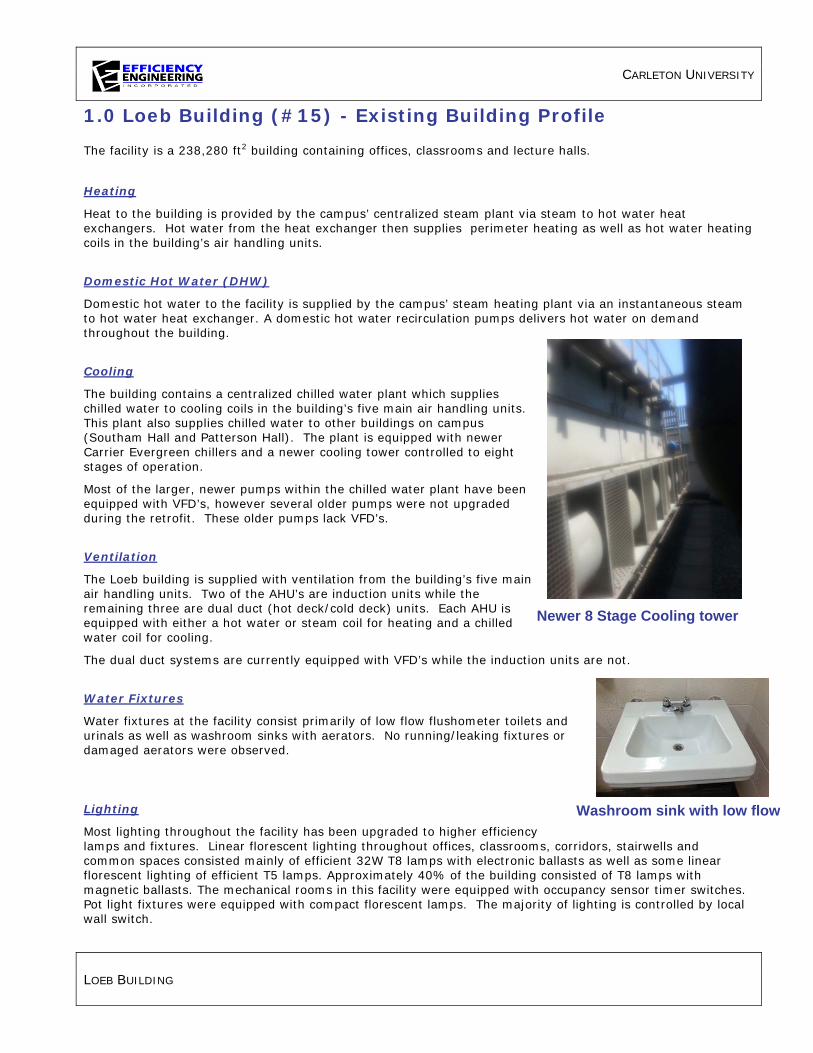
CARLETON UNIVERSITY
LOEB BUILDING
1.0 Loeb Building (#15) - Existing Building Profile
The facility is a 238,280 ft2 building containing offices, classrooms and lecture halls.
Heating
Heat to the building is provided by the campus’ centralized steam plant via steam to hot water heat exchangers. Hot water from the heat exchanger then supplies perimeter heating as well as hot water heating coils in the building’s air handling units.
Domestic Hot Water (DHW)
Domestic hot water to the facility is supplied by the campus’ steam heating plant via an instantaneous steam to hot water heat exchanger. A domestic hot water recirculation pumps delivers hot water on demand throughout the building.
Cooling
The building contains a centralized chilled water plant which supplies chilled water to cooling coils in the building’s five main air handling units. This plant also supplies chilled water to other buildings on campus (Southam Hall and Patterson Hall). The plant is equipped with newer Carrier Evergreen chillers and a newer cooling tower controlled to eight stages of operation.
Most of the larger, newer pumps within the chilled water plant have been equipped with VFD’s, however several older pumps were not upgraded during the retrofit. These older pumps lack VFD’s.
Ventilation
The Loeb building is supplied with ventilation from the building’s five main air handling units. Two of the AHU’s are induction units while the remaining three are dual duct (hot deck/cold deck) units. Each AHU is equipped with either a hot water or steam coil for heating and a chilled water coil for cooling.
The dual duct systems are currently equipped with VFD’s while the induction units are not.
Water Fixtures
Water fixtures at the facility consist primarily of low flow flushometer toilets and urinals as well as washroom sinks with aerators. No running/leaking fixtures or damaged aerators were observed.
Lighting
Most lighting throughout the facility has been upgraded to higher efficiency lamps and fixtures. Linear florescent lighting throughout offices, classrooms, corridors, stairwells and common spaces consisted mainly of efficient 32W T8 lamps with electronic ballasts as well as some linear florescent lighting of efficient T5 lamps. Approximately 40% of the building consisted of T8 lamps with magnetic ballasts. The mechanical rooms in this facility were equipped with occupancy sensor timer switches. Pot light fixtures were equipped with compact florescent lamps. The majority of lighting is controlled by local wall switch.
Newer 8 Stage Cooling tower
Washroom sink with low flow

CARLETON UNIVERSITY
LOEB BUILDING
2.0 Energy Savings Scenario
The Energy Savings Scenario consists of all Opportunities that are recommended based primarily on the energy and utility cost saving benefits.
M01 – Lighting Upgrade: Occupancy Sensors
M01.1 - Existing Conditions
Lighting is primarily controlled by local wall switch. Many lights are left on when rooms remain unoccupied. Corridors are typically left on 24/7.
M01.2 - Retrofit Conditions
We recommend installing occupancy sensors in many of the offices, classrooms, corridors, and storage rooms. Typical energy savings range from 30%-60%, depending on the pattern and frequency of room use. It is important that qualified contractors are familiar with all building code and by law requirements regarding the installation of occupancy sensors, lighting level requirements and fire code. Safety of occupants should always be addressed when determining suitable applications for occupancy sensors.
M02 – Install VFD’s on Induction Units A/B, C/D
M02.1 - Existing Conditions
The two induction air handling units bring in controlled amounts of ventilation air and blend it with return air before delivering it to terminal units located around the facility. Each of the AHU’s is equipped with a hot water coil and a chilled water coil which provides heating and cooling.
The fans for each of these AHU’s is sized to supply adequate air flows during times of peak heating, cooling or ventilation load requirements. Some of the AHU’s are currently equipped with VFD’s or variable inlet vanes to reduce air flows during off peak times. Several of the AHU’s, however, lack any type of air flow control.
M02.2 - Retrofit Conditions
We recommend installing a variable frequency drives (VFD’s) and inverter duty motors on the supply and return fans of Induction Units A/B and C/D. Fan speeds will modulate to maintain space temperature set points in each zone of the air handling unit. As a space calls for heating, the heating control valve for the reheat coil will open. If space temperature cannot be maintained once the reheat coil has reached 100%, the fan speed will ramp up to provide more heat to the space.
M03 – Install VFD’s on Dual Temperature Distribution Pumps
M03.1 - Existing Conditions
Two 15 hp dual temperature distribution pumps, BA and BB, circulate water through the dual temperature loop throughout the building supplying perimeter heating and heating and cooling coils in the AHU’s.
The pumps operate in a Primary/Stand-by configuration. One pump operates continuously, 24/7, while the secondary pump cycles on if the primary pump were to fail.

CARLETON UNIVERSITY
LOEB BUILDING
M05.2 - Retrofit Conditions
We recommend installing a variable frequency drive (VFD) and inverter duty motor on the primary dual temperature distribution pump. The VFD will allow the pump speed to modulate to match the heating and cooling loads on the system at all times. Drive speeds will modulate based on supply/return temperature differential. If the primary pump or the VFD were to fail the secondary pump would run during the repair of the primary pump or VFD.
The costing and payback for this measure include installing a VFD on the “primary” pump only. A VFD can also be installed on the secondary pump in this system. Installation of the VFD on the standby pump would approximately double the implementation cost of the measure. As the standby pump in this system operates only occasionally, however, the energy and dollars saved would not increase significantly. We recommend installing a VFD on the primary pump only to minimize installation costs and to provide the most attractive payback for the measure.
M04 – Install VFD’s on Chilled Water Pumps
M04.1 - Existing Conditions
Five distribution pumps, P15-15, -16, -17, -18, and -19 circulate chilled water throughout the building supplying cooling coils in the AHU’s as well as supplying two additional buildings with chilled water.
Pumps P15-15 and P15-16 operate in a Primary/Stand-by configuration. One pump operates continuously, 24/7, while the secondary pump cycles on if the primary pump were to fail.
Pumps P15-17, -18 and -19 turn on automatically with the chilled water plant.
M06.2 - Retrofit Conditions
We recommend installing variable frequency drives (VFD’s) and inverter duty motors on the five chilled water pumps. The VFD’s will allow pump speeds to modulate to match the cooling loads on the system at all times. Drive speeds will modulate based on supply/return temperature differential. If the primary pump or the VFD were to fail the secondary pump would run during the repair of the primary pump or VFD.
The costing and payback for this measure include installing a VFD on the “primary” pump (P15-15) and secondary pump (P15-16) as it still provides an attractive payback for the measure.
M05 – Install VFD’s on Domestic Water Booster Pumps
M05.1 - Existing Conditions
Two 7.5 hp domestic water booster pumps supply the necessary water pressure for the building. One pump runs continuously while the other pump cycles on only during times of peak loads (high domestic water consumption). As this building consists mainly of office and classroom spaces, the domestic water load is likely fairly constant throughout the occupied hours. This results very short intervals of high demand when the second booster pump would be required.
M05.2 - Retrofit Conditions
We recommend installing a variable speed drive and inverter duty motor on the primary domestic booster pump. Any PRV’s on the main line leading to the mechanical room should be opened completely or entirely removed to reduce the system losses. A pressure sensor would be installed in the penthouse with the VFD modulating to maintain water pressure (say 20 psig) at that point.

CARLETON UNIVERSITY
LOEB BUILDING
As the second domestic water booster pump runs for only very short periods of time throughout the day, installing a VFD on this pump would significantly increase the implementation cost of this measure, but would not increase the savings proportionally.
The costing and payback for this measure include installing a VFD on the “primary” pump only. A VFD can also be installed on the secondary pump in this system. Installation of the VFD on the standby pump would approximately double the implementation cost of the measure. As the standby pump in this system operates only occasionally, however, the energy and dollars saved would not increase significantly. We recommend installing a VFD on the primary pump only to minimize installation costs and to provide the most attractive payback for the measure.
M06 – Reschedule AHU-5 (Level 1&2), Cycle on/off based on Temperature
M06.1 - Existing Conditions
AHU-5 is currently scheduled to run 24 hours a day 7 days a week. This AHU is a mixed air unit equipped with a hot water coil and a chilled water coil which provides heating and cooling to level 1 and 2 of the building. The fans run for long hours including evenings, nights and weekends.
The fans for the AHU are sized to supply adequate air flows during times of peak heating, cooling or ventilation load requirements.
M06.2 - Retrofit Conditions
We recommend implementing a schedule based on actual occupancy of the building and controlling it to outdoor temperatures. The unit will cycle the supply and return fans on/off based on outdoor air temperature to reduce the run time of the fans during unoccupied times (evenings, weekends, during extended breaks) while ensuring the temperature of the supplied area never falls below a minimum temperature. This will reduce the unnecessary amount of fan runtime. Implementation costs for this measure are relatively low. As all of the controls exist, only updating of the building automation system would be required.
M07 – Lighting Upgrade: High Performance T8 Retrofit
M07.1 - Existing Conditions
Approximately 40% of this facility contained linear fluorescent fixtures that house 32 watt T8 lamps and inefficient magnetic ballasts. Some ballasts have been updated to electronic ballasts as they fail.
M07.2 - Retrofit Conditions
We recommend retrofitting existing 4ft T8 fixtures with reduced wattage (25w) lamps and high efficiency electronic ballasts. A high performance retrofit achieves 37% savings over the existing system.
July 1, 2010 saw the ban of magnetic ballast production in Canada. This includes the large majority of T12 and T8 magnetic ballasts. This means that when a magnetic ballast fails it must be replaced with an electronic ballast. There are many benefits to changing to electronic ballasts, well beyond the improved efficiency. Total Harmonic Distortion (THD) is greatly reduced. The “flicker” and “hum” that magnetic systems are notoriously known for are greatly reduced. Electronic ballasts have longer average life spans, improve lamp life and because they can drive up to 4 lamps versus just 1 or 2 lamps, and they create less waste.

CARLETON UNIVERSITY
LOEB BUILDING
M08 – Implement “Partial Occupancy” Schedule – AHU’s-1, -2, -3, -4, -5
M08.1 - Existing Conditions
Ventilation to the building is provided by several mixed air handling units. These units bring in fixed amounts of outdoor air and blend it with return air before returning it to the space. Any outdoor air brought into the building must be heated or cooled by the building’s HVAC systems, so it’s best to minimize it.
The AHU’s bring in a variable amount of outdoor air based on outdoor and supply air temperatures. The minimum amount of outdoor air being brought in by a particular AHU is controlled by the minimum outdoor air damper position set at the BAS. Typically, the minimum ventilation level (minimum outdoor air damper position), would be set to provide adequate ventilation during times of peak occupancy (fully occupied hours). Any outside air brought into the building has to be conditioned by heating or cooling equipment, so it is best to minimize it.
Currently, the air handling units operate seven days per week, 365 days per year. They typically operate from 6 in the morning through until 10 at night with slightly reduced hours on weekends. During these hours of operation, the units are bringing in ventilation air at a rate based on the minimum outdoor air damper position (15%). This minimum ventilation rate is typically based on the expected normal peak occupancy of the building.
The building is primarily used as offices, classrooms and lecture halls with peak occupancy occurring during normal business hours, Monday-Friday from 8am to 5pm. Occupancy during early morning, late evening and weekend periods is drastically lower. Currently, however, the AHU’s continue to bring in large amounts of ventilation air during these times of “partial occupancy”.
M08.2 - Retrofit Conditions
We recommend implementing a “Partial Occupancy” schedule to reduce the amount of fresh air supplied during times of lower occupancy (evenings, weekends, during extended breaks). The existing Occupied/Unoccupied schedule for the AHU’s will be updated to include a “Partial Occupancy” schedule at the beginning and end of each day as well as over weekends and during summer and winter breaks as appropriate. During the scheduled “Partial Occupancy” hours, the minimum outdoor air damper position will be reset to a lower value than the current occupied hours minimum to reflect the greatly reduced occupancy loads. This will reduce unnecessary amounts of outdoor air needing to be conditioned. Implementation costs for this measure are relatively low for the scheduling. As all of the controls exist, only updating of the building automation system would be required.
M09 – Lighting Upgrade: Incandescent to CFL
M09.1 - Existing Conditions
There is still a small amount of incandescent lighting throughout this facility.
M09.2 - Retrofit Conditions
We recommend replacing incandescent lamps with equivalent compact fluorescent lamps (CFLs). There are compact fluorescent lamps (CFLs) on the market today to be utilized in almost any application. In preparation for the 2014 ban on “General Use” incandescent lamps, companies are producing quality CFLs which produce light of similar colour and lumen output as incandescent, all while consuming less than ¼ of the energy and lasting 10 times longer than standard incandescent bulbs.

CARLETON UNIVERSITY
LOEB BUILDING
M10 – Water Conservation: Ultra Low Flow Aerators
M10.1 - Existing Conditions
All of the toilets and urinals throughout the building are low flow fixtures. The sinks located throughout the building have standard (2.2 gpm) aerators installed.
M10.2 - Retrofit Conditions
We recommend installing ultra low flow, 0.5 GPM, aerators on all faucets to further reduce water consumption.
M11 – Campus Wide Integrated Lighting Controls
M11.1 - Existing Conditions
Many of the building’s offices, classrooms and lecture halls are being controlled by local wall switches. In many cases lights remain on longer than the space is occupied.
M11.2 - Retrofit Conditions
An efficient integrated lighting control system should take advantage of savings through time scheduling, daylight harvesting, task tuning, occupancy control, personal control and variable load shedding. Combined effectively, these methods can result in 50-75% energy savings.
To achieve maximal energy savings an effective integrated lighting control system should provide: • a user friendly interface that would allow on site staff to control lighting throughout the entire
facility or campus using a point and click set up (interface can be on a network PC system or web-based for ultimate control for future portfolio monitoring and control)
• the ability to adjust settings, limits, and time schedules on event specific, daily, weekly, or monthly basis
• allow for interface with HVAC and Security control systems and equipment to share data such as occupancy status and adjust for status. This type of system would allow individuals to immediately identify which areas of a building or campus are occupied at what hours, providing additional information to security personnel.
• allow monitoring of occupancy sensors, dimmers and wall switches to enable zones to be configured such that only the fixtures in that entrance and exit pathway or area shall be left on.
• allow for personal settings to be adjusted and set for specific fixtures or group of fixtures. This can increase productivity as it ensures that individuals can select the amount of light that best enables them to perform a task.
• the ability to illustrate and report consumption, light levels, light status, power density, and occupancy status help ensure that the system is being effectively utilized while also having the added benefit of simple assurance that all individuals have vacated the facility.
We recommend that a high performance integrated lighting control system meeting the above criteria be installed campus wide.
As electrical rates and time of use charges increase, it is becoming more critical that energy savings are achieved not only by installing efficient lighting but by controlling the way and time of use lighting is utilized.

CARLETON UNIVERSITY
HHJ NESBITT BUILDING PAGE 1
1.0 HHJ Nesbitt Building (#16) - Existing Building Profile
The facility consists of a 68,000 ft2 building containing offices, classrooms, labs and greenhouses.
Heating
Heat to the building is provided by the campus’ centralized steam plant via steam to hot water heat exchangers. Hot water from the heat exchanger then supplies perimeter heating as well as hot water heating coils in the building’s four main air handling units.
Domestic Hot Water (DHW)
Domestic hot water to the facility is supplied by the campus’ steam heating plant via an instantaneous steam to hot water heat exchanger. A domestic hot water recirculation pumps delivers hot water on demand throughout the building.
Cooling
Cooling for the building is provided by chilled water from a remote source. Chilled water is supplied to cooling coils in the building’s four main air handling units.
Ventilation
The Nesbitt Building is supplied with ventilation from the building’s four main air handling units. Each AHU is equipped with a hot water coil for heating and a chilled water coil for cooling.
All units except for AHU-4 (5 hp) are currently equipped with VFD’s.
Water Fixtures
Water fixtures at the facility consist primarily of low flow flushometer toilets as well as washroom sinks with aerators. No running/leaking fixtures or damaged aerators were observed.
Lighting
Most lighting throughout the facility has been upgraded to higher efficiency lamps and fixtures. Linear florescent lighting throughout offices, classrooms, corridors, stairwells and common spaces consisted of efficient 32W T8 lamps with electronic ballasts. Some corridors and pot light fixtures were equipped with compact florescent lamps. Exit signs have been converted to LEDs. The majority of lighting is controlled by local wall switch.
Exceptional Equipment A single pass water cooled heat pump located in the basement mechanical room supplies temperature control to laboratory aquariums. Condenser water from this heat pump passes through the unit and goes directly to drain.
32W T8 Lighting

CARLETON UNIVERSITY
HHJ NESBITT BUILDING PAGE 2
2.0 Energy Savings Scenario
The Energy Savings Scenario consists of all Opportunities that are recommended based primarily on the energy and utility cost saving benefits.
M01 – Lighting Controls: Occupancy Sensors
M01.1 - Existing Conditions
Lighting is primarily controlled by local wall switch. Many office and classroom lights are left on when rooms remain unoccupied. Corridors are typically left on 24/7.
M01.2 - Retrofit Conditions
We recommend installing occupancy sensors in many of the offices, classrooms, corridors, and storage rooms. Typical energy savings range from 30%-60%, depending on the pattern and frequency of room use. It is important that qualified contractors are familiar with all building code and by law requirements regarding the installation of occupancy sensors, lighting level requirements and fire code. Safety of occupants should always be addressed when determining suitable applications for occupancy sensors.
M02 – Re-commission Hot Water Pumps P-8 and P-9 VFD, Reading 9Hz
M02.1 - Existing Conditions
The VFD controlling P-8 and P-9 was malfunctioning at the time of the audit. The pumps circulate heating hot water throughout the building supplying perimeter heating and heating coils in the AHU’s.
The pumps operate in a Primary/Stand-by configuration. One pump operates continuously, 24/7, while the secondary pump cycles on if the primary pump were to fail.
At the time of the audit, the VFD controlling the primary pump was displaying a reading of 9Hz which is below the operational capacity of most pumps.
M02.2 - Retrofit Conditions
We recommend re-commissioning the variable frequency drives (VFD) on pumps P-8 and P-9. The VFD allows the pump speed to modulate to match the heating loads on the system at all times. It is suspected that the existing drive requires maintenance or, possibly, replacement.
M03 – Install VFD on P-12 to AHU-2, AHU-3
M03.1 - Existing Conditions
One 5 hp pump, P-12, circulates heating hot water through heating coils in AHU-2 and AHU-3.
The pump operates continuously, 24/7, during the heating season.
M03.2 - Retrofit Conditions
We recommend installing a variable frequency drive (VFD) and inverter duty motor on the heating hot water pump. The VFD will allow the pump speed to modulate to match the heating loads on the system at all times. Drive speeds will modulate based on supply/return temperature differential.

CARLETON UNIVERSITY
HHJ NESBITT BUILDING PAGE 3
M04 – Install VFD on AHU-4, Remove Bypass
M04.1 - Existing Conditions
All of the buildings AHU’s are mixed air units, with the exception of the make-up air unit (AHU-2), which bring in controlled amounts of ventilation air and blend it with return air before delivering it to specific areas of the facility. Each of the AHU’s is equipped with a hot water coil and a chilled water coil which provides heating and cooling.
The fans for each of these AHU’s is sized to supply adequate air flows during times of peak heating, cooling or ventilation load requirements. Some of the AHU’s are currently equipped with VFD’s to reduce air flows during off peak times. AHU-4, however, lacks flow control.
M02.2 - Retrofit Conditions
We recommend removing the fan bypass duct on AHU-4 and installing variable frequency drives (VFD’s) and inverter duty motors on the supply and return fans of AHU-4. Fan speeds will modulate to maintain space temperature set points in each zone of the air handling unit. As a space calls for heating, the heating control valve for the reheat coil will open. If space temperature cannot be maintained once the reheat coil has reached 100%, the fan speed will ramp up to provide more heat to the space.
M05 – Implement “Partial Occupancy” Schedule on AHU-1
M05.1 - Existing Conditions
Ventilation to the building is provided by several mixed air handling units and one make-up air unit. These units bring in fixed amounts of outdoor air and blend it with return air before returning it to the space. Any outdoor air brought into the building must be heated or cooled by the building’s HVAC systems, so it’s best to minimize it.
The AHU’s bring in a variable amount of outdoor air based on outdoor and supply air temperatures. The minimum amount of outdoor air being brought in by a particular AHU is controlled by the minimum outdoor air damper position set at the BAS. Typically, the minimum ventilation level (minimum outdoor air damper position), would be set to provide adequate ventilation during times of peak occupancy (fully occupied hours). Any outside air brought into the building has to be conditioned by heating or cooling equipment, so it is best to minimize it.
Currently, the air handling units operate seven days per week, 365 days per year. They typically operate from 7 in the morning through until 9 at night with slightly reduced hours on weekends. During these hours of operation, the units are bringing in ventilation air at a rate based on the minimum outdoor air damper position (15%). This minimum ventilation rate is typically based on the expected normal peak occupancy of the building.
The building is primarily used as offices, classrooms, labs and greenhouses with peak occupancy occurring during normal business hours, Monday-Friday from 8am to 5pm. Occupancy during early morning, late evening and weekend periods is drastically lower. Currently, however, the AHU’s continue to bring in large amounts of ventilation air during these times of “partial occupancy”.
M05.2 - Retrofit Conditions
We recommend implementing a “Partial Occupancy” schedule to reduce the amount of fresh air supplied during times of lower occupancy (evenings, weekends, during extended breaks). The existing Occupied/Unoccupied schedule for the AHU’s will be updated to include a “Partial Occupancy” schedule at the beginning and end of each day as well as over weekends and during summer and winter breaks

CARLETON UNIVERSITY
HHJ NESBITT BUILDING PAGE 4
as appropriate. During the scheduled “Partial Occupancy” hours, the minimum outdoor air damper position will be reset to a lower value than the current occupied hours minimum to reflect the greatly reduced occupancy loads. This will reduce unnecessary amounts of outdoor air needing to be conditioned. Implementation costs for this measure are relatively low for the scheduling. As all of the controls exist, only updating of the building automation system would be required.
M06 – Water Conservation: Replace Single Pass Dry-O-Tron Unit
M06.1 - Existing Conditions
A single pass water cooled heat pump located in the basement mechanical room supplies the laboratory aquarium room. Condenser water from this heat pump passes through the unit and goes directly to drain. This system may no longer meet code requirements.
M06.2 - Retrofit Conditions
We recommend installing an air source heat pump instead of the single pass water cooled heat pump. The savings will come from water and sewage charges on the water going directly to the drain.
M07 – Water Conservation: Ultra Low Flow Aerators
M07.1 - Existing Conditions
All of the toilets and urinals throughout the building are low flow fixtures. The sinks located throughout the building have standard (2.2 gpm) aerators installed.
M07.2 - Retrofit Conditions
We recommend installing ultra low flow, 0.5 GPM, aerators on all faucets to further reduce water consumption.
M08 – Campus Wide Integrated Lighting Controls
M08.1 - Existing Conditions
Many of the building’s offices, classrooms, laboratories and lecture halls are being controlled by local wall switches. In many cases lights remain on longer than the space is occupied.
M08.2 - Retrofit Conditions
An efficient integrated lighting control system should take advantage of savings through time scheduling, daylight harvesting, task tuning, occupancy control, personal control and variable load shedding. Combined effectively, these methods can result in 50-75% energy savings.
To achieve maximal energy savings an effective integrated lighting control system should provide: • a user friendly interface that would allow on site staff to control lighting throughout the entire
facility or campus using a point and click set up (interface can be on a network PC system or web-based for ultimate control for future portfolio monitoring and control)
• the ability to adjust settings, limits, and time schedules on event specific, daily, weekly, or monthly basis
• allow for interface with HVAC and Security control systems and equipment to share data such as occupancy status and adjust for status. This type of system would allow individuals to immediately identify which areas of a building or campus are occupied at what hours, providing additional information to security personnel.
• allow monitoring of occupancy sensors, dimmers and wall switches to enable zones to be

CARLETON UNIVERSITY
HHJ NESBITT BUILDING PAGE 5
configured such that only the fixtures in that entrance and exit pathway or area shall be left on.
• allow for personal settings to be adjusted and set for specific fixtures or group of fixtures. This can increase productivity as it ensures that individuals can select the amount of light that best enables them to perform a task.
• the ability to illustrate and report consumption, light levels, light status, power density, and occupancy status help ensure that the system is being effectively utilized while also having the added benefit of simple assurance that all individuals have vacated the facility.
We recommend that a high performance integrated lighting control system meeting the above criteria be installed campus wide.
As electrical rates and time of use charges increase, it is becoming more critical that energy savings are achieved not only by installing efficient lighting but by controlling the way and time of use lighting is utilized. Typically the installation of an integrated lighting control system has a simple payback of 2-5 years.
M09 – Install Heat Reclaim on AHU-2
M09.1 - Existing Conditions
AHU-2 is a 100% outdoor air make up air unit that brings in ventilation air that is exhausted by a large dedicated exhaust fan. This unit brings in a lot of outdoor air. Any outdoor air brought into the building must be heated or cooled by the building’s HVAC systems, so it’s best to minimize it.
M09.2 - Retrofit Conditions
We recommend installing a heat reclaim unit with a glycol loop to precondition the outdoor air being brought in to the building. By reclaiming the heat from the exhaust air and preconditioning the incoming outdoor air, will reduce the heating and cooling loads required to condition the incoming air.

CARLETON UNIVERSITY
DUNTON TOWER PAGE 1
1.0 Dunton Tower (#21) - Existing Building Profile
The facility is a 184,803 ft2, 24 story building which serves primarily as offices.
Heating
Heat to the building is provided by the campus’ centralized steam plant via steam convertors. Hot water from the heat exchanger then supplies induction unit reheat coils throughout the building as well as hot water and preheat coils in the building’s four air handling units.
Domestic Hot Water (DHW)
Domestic hot water to the facility is supplied by an instantaneous heat exchanger which draws from the Universities centralized steam plant and includes a recirculation loop and pump.
Cooling
The entire facility is supplied with air conditioning.
It is equipped with a Carrier chiller and BAC cooling tower. The chilled water from CH-1 supplies AHU-1,2 and 3 as well as the perimeter induction unit coils.
Ventilation
Dunton Tower is supplied with ventilation from the building’s four air handling units located in penthouse and basement mechanical rooms. AHU-1 and 3 are equipped with a preheat coil, cooling coil, and a heating coil. AHU-2 is equipped with a heating coil and cooling coil. AHU-4 is equipped with a single heating coil. All the AHU’s provide mixed air ventilation for the various zones within the building.
The BAS controls the ventilation from a programmed schedule based on occupancy.
The supply and return fans of AHU-1 are equipped with VFD’s.
Water Fixtures
Water fixtures at the facility consist of low flow flushometer toilets and kitchenette and washroom sinks with standard aerators. No running/leaking fixtures or damaged aerators were observed.
Lighting
Lighting in this facility is primarily T8 with magnetic ballast. There are several T12 linear fluorescent fixtures with magnetic ballasts located in the basement and elevators. The 2nd floor elevator lobby houses metal halide pendant fixtures. Pot lights house compact fluorescent lamps. There are several halogen lamps located on the 17th floor. Some pot light fixtures which typically house halogen lamps have been undated to LED. Exit signs are LED. Exterior fixtures are a mixture of high pressure sodium and metal halide wall packs and poles.
2.0 Energy Savings Scenario
The Energy Savings Scenario consists of all Opportunities that are recommended based primarily on the energy and utility cost saving benefits.

CARLETON UNIVERSITY
DUNTON TOWER PAGE 2
M01 – Re-commission AHU-3
M01.1 - Existing Conditions
This air handling unit was observed to have either malfunctioning equipment or BAS issues. The readings from the BAS screenshots show that the sequence of operation is not optimized or that equipment (sensors) are not functioning properly. Although the system is in operation and no alarms are present, the temperature measurements were observed to fluctuate without reason, possibly due to malfunctioning sensors or improper sequencing of the BAS.
M01.2 - Retrofit Conditions
We recommend re-commissioning this unit along with the BAS controls equipment to insure proper operation and monitoring of the system.
M04 – Control P-28 to Turn Off
M04.1 - Existing Conditions
The building has a small pump which circulates a glycol loop for preheating coils. These coils serve as preheat for colder outdoor temperatures, but it was observed in June that the pump was still circulating the glycol.
M04.2 - Retrofit Conditions
It is recommended that the pump is equipped with a controller which turns the pump off when the outdoor air temperature rises above a set point (~38 oF), and turns on when it drops below that set point. This will reduce the pumping hours of the unit when preheating is not necessary and will reduce the electrical consumption.
M05 – Static Pressure Reset Control for AHU-1 and 2
M05.1 - Existing Conditions
The Dunton Tower has a two air handling units equipped with VFDs. They modulate their speed to maintain a constant static pressure and are scheduled to operate during occupied hours of the building. Typically when VAV boxes close, they dump their excess air flow into the ceiling spaces,

CARLETON UNIVERSITY
DUNTON TOWER PAGE 3
which wastes heating, cooling and ventilation energy.
M05.2 - Retrofit Conditions
It is recommended that VAV boxes are equipped with damper position indicators. The indicators will allow the fans to slow down based on the position of the VAV dampers. When the dampers close because heating/cooling is no longer required to the zones, the VFDs will slow the fan motors down to a minimum. When the dampers begin to open, the VFDs will ramp up the speed of the fan motors accordingly.
M06 – Lighting Upgrade: T8 High Performance System
M06.1 - Existing Conditions
A large majority of the linear fluorescent fixtures in this building house 32 watt T8 lamps and inefficient magnetic ballasts. Some ballasts have been updated to electronic ballasts as they fail. A few areas in the basement and elevators still house T12 lamps and magnetic ballasts.
M06.2 - Retrofit Conditions
We recommend retrofitting existing 4ft T8 fixtures with reduced wattage (25w) lamps and high efficiency electronic ballasts. A high performance retrofit achieves 37% savings over the existing system.
We recommend retrofitting all T12 fixtures with high efficiency electronic ballasts and corresponding lamps specific to fixture length.
July 1, 2010 saw the ban of magnetic ballast production in Canada. This includes the large majority of T12 and T8 magnetic ballasts. This means that when a magnetic ballast fails it must be replaced with an electronic ballast. There are many benefits to changing to electronic ballasts, well beyond the improved efficiency. Total Harmonic Distortion (THD) is greatly reduced. The “flicker” and “hum” that magnetic systems are notoriously known for are greatly reduced. Electronic ballasts have longer average life spans, improve lamp life and because they can drive up to 4 lamps versus just 1 or 2 lamps, and they create less waste.
M07- Lighting Upgrade: LED Retrofit
M07.1 - Existing Conditions
The 17th Floor lecture room still houses many halogen lamps on dimmer control.
M07.2 - Retrofit Conditions
We recommend replacing all interior halogen lamps with quality LED equivalents.
Currently the top choice in dimmable efficient lighting technology is LED. Quality LEDs have the ability to maintain warm colour temperatures while dimming to 10% and achieving efficacy of 60-90 lumens per watt while lasting 25,000 – 50,000 hours.
Care should be taken in selecting a quality LED which meets the needs of the application while being supported by a reputable company guaranteeing a lengthy warranty. Energy Star certification requires that energy and other identified performance parameters of the LEDs can be consistently measured and verified through testing. Energy Star certification should be the minimum requirement in choosing any energy efficient lighting product.

CARLETON UNIVERSITY
DUNTON TOWER PAGE 4
M08 – Lighting Controls: Occupancy Sensors
M08.1 - Existing Conditions
Lighting is primarily controlled by local wall switch. Many lights are left on when rooms remain unoccupied. Corridors are typically left on 24/7.
M08.2 - Retrofit Conditions
We recommend installing occupancy sensors in many of the offices, classrooms, corridors, and storage rooms. Typical energy savings range from 30%-60%, depending on the pattern and frequency of room use. It is important that qualified contractors are familiar with all building code and by law requirements regarding the installation of occupancy sensors, lighting level requirements and fire code. Safety of occupants should always be addressed when determining suitable applications for occupancy sensors.
M09 – Water Conservation: Install Ultra Low Flow 0.5 gpm Faucet Aerators
M09.1 - Existing Conditions
Water faucets throughout the building are currently equipped with standard 2.2 gallon per minute (gpm) aerators in the washrooms.
M09.2 - Retrofit Conditions
We recommend installing ultra low flow faucet aerators on all existing faucets with 2.2 gpm aerators. These ultra low flow aerators supply hand sanitation at a much lower flow rate at 0.5 gpm.
M10 – Campus Wide Integrated Lighting Controls
M10.1 - Existing Conditions
Lighting is primarily controlled by local wall switch. Many lights are left on when areas remain unoccupied or in areas where adequate natural light is illuminating the area. Corridors are typically left on 24/7.
M10.2 - Retrofit Conditions
An efficient integrated lighting control system should take advantage of savings through time scheduling, daylight harvesting, task tuning, occupancy control, personal control and variable load shedding. Combined effectively, these methods can result in 50-75% energy savings. To achieve maximal energy savings an effective integrated lighting control system should provide:
• a user friendly interface that would allow on site staff to control lighting throughout the entire
facility or campus using a point and click set up (interface can be on a network PC system or web-based for ultimate control for future portfolio monitoring and control)
• the ability to adjust settings, limits, and time schedules on event specific, daily, weekly, or monthly basis
• allow for interface with HVAC and Security control systems and equipment to share data such as occupancy status and adjust for status. This type of system would allow individuals to immediately identify which areas of a building or campus are occupied at what hours, providing additional information to security personnel.

CARLETON UNIVERSITY
DUNTON TOWER PAGE 5
• allow monitoring of occupancy sensors, dimmers and wall switches to enable zones to be configured such that only the fixtures in that entrance and exit pathway or area shall be left on.
• allow for personal settings to be adjusted and set for specific fixtures or group of fixtures. This can increase productivity as it ensures that individuals can select the amount of light that best enables them to perform a task.
• the ability to illustrate and report consumption, light levels, light status, power density, and occupancy status help ensure that the system is being effectively utilized while also having the added benefit of simple assurance that all individuals have vacated the facility.
We recommend that a high performance integrated lighting control system meeting the above criteria be installed campus wide. As electrical rates and time of use charges increase, it is becoming more critical that energy savings are achieved not only by installing efficient lighting but by controlling the way and time of use lighting is utilized.
3.0 Longer Payback Scenario
The Longer Payback Scenario consists of Opportunities that are not as financially attractive as the Energy Savings Scenario. These measures should be considered when equipment failure occurs or as Capital Renewal projects as equipment reaches its end of life.
M03 – Install VFD’s on AHU-3 and 4
M03.1 - Existing Conditions
AHU-3 and 4 currently are mixed air units which provide a constant volume of air. The units supply the 2nd floor lobby (AHU-3) and basement (AHU-4). These units are sized to provide adequate air flow during times of peak heating and cooling loads.
M03.2 - Retrofit Conditions
It is recommended that the supply and return fans are equipped with variable frequency drives (VFDs) to modulate the flow of supply air based on outdoor air temperature. During the “shoulder seasons” when heating and cooling loads are lower than peak, fan speeds will be reduced to supply a lower air flow. As heating/cooling requirements increase, fan speeds will increase accordingly based on outdoor air temperatures (outdoor air temperature reset curve).

CARLETON UNIVERSITY
ARCHITECTURE BUILDING PAGE 1
1.0 Architecture Building (#22) - Existing Building Profile
The facility is a 92,687 ft2, 5 story building which serves primarily as offices along with some classroom and auditorium space.
Heating
Heat to the building is provided by the campus’ centralized steam plant via shell and tube heat exchangers. Hot water from the heat exchanger (MTHW) then supplies a perimeter heating loop as well as hot water coils in the building’s two main air handling units.
Domestic Hot Water (DHW)
Domestic hot water to the facility is stored in a tank which is fed off MTHW through a heat exchanger which draws from the Universities centralized steam plant and has an electric heater assist.
Cooling
The entire facility is supplied with air conditioning.
It is supplied chilled water from the Tory building’s chilled water plant which feeds the cooling coils in AHU-1 and AHU-2.
Ventilation
The Architecture building is supplied with ventilation from the building’s 2 main air handling units located on the 5th floor in the mechanical rooms. Each AHU is equipped with a preheat, hot water and a chilled water coil to provide conditioned air as well as ventilation throughout the building.
CO2 levels are monitored by the BAS which adjusts the outdoor air ventilation levels to maintain indoor air quality. This allows ventilation levels to be minimized, especially during unoccupied overnight and weekend hours.
The supply and return fans of AHU-1 and AHU-2 are equipped with variable inlet vanes (VIV’s).
Water Fixtures
Water fixtures at the facility consist of low flow flushometer toilets and kitchen and washroom sinks with aerators. No running/leaking fixtures or damaged aerators were observed.
Lighting
Lighting is primarily 32 watt T8 linear fluorescent lamps with electronic ballasts. Pot lighting is primarily compact fluorescent. Incandescent lamps remain in the 2nd floor library/lounge. Interior lighting is controlled primarily by local wall switch with several occupancy sensors in washrooms throughout the building. The building was designed to allow abundant natural light into the interior space. All exit signs are LED. Exterior lighting is high pressure sodium.
2.0 Energy Savings Scenario
The Energy Savings Scenario consists of all Opportunities that are recommended based primarily on the energy and utility cost saving benefits.
CARLETON UNIVERSITY
ARCHITECTURE BUILDING PAGE 2
M01 – Install Control Valves on Steam Supply
M01.1 - Existing Conditions
All the heat exchangers throughout the building were observed to be turned on during the site visit.
M01.2 - Retrofit Conditions
This measure involves installing control valves on the heat exchangers to control the flow of heating based on the demand of the building. This will lower the baseline demand from the MTHW heating plant.
M02 – Replace VIV’s with VFD’s on AHU-1 Supply and Return Fans
M02.1 - Existing Conditions
AHU-1 currently has supply and return fans which are equipped with variable inlet vanes (VIV’s). These types of fans are able to modulate the pitch of their blades to control the volume of supplied air.
M02.2 - Retrofit Conditions
This retrofit recommends the removal of the VIV’s and the installation of VFD’s with inverter duty fan motors. The VFD’s will control the volume of supply air by modulating the speed of the fans based on the mixed air temperature and set point. This is a more efficient way of controlling the air flow and lowering the consumption of the fans.
M05 – Lighting Upgrade: Incandescent to CFL
M05.1 - Existing Conditions
The 2nd floor library/lounge currently houses incandescent lamps in recessed fixtures.
M05.2 - Retrofit Conditions
We recommend replacing incandescent lamps with equivalent compact fluorescent lamps (CFLs). There are compact fluorescent lamps (CFLs) on the market today to be utilized in almost any application. In preparation for the 2014 ban on “General Use” incandescent lamps, companies are producing quality CFLs which produce light of similar colour and lumen output as incandescent, all while consuming less than ¼ of the energy and lasting 10 times longer than standard incandescent bulbs.
M06 – Install Demand Control Ventilation on AHU’s
M06.1 - Existing Conditions
The building’s air handling units currently supply air based on the temperature of the return air, and the outdoor air dampers are set in a fixed position.
M06.2 - Retrofit Conditions
It is recommended that the AHU’s operate their fans to control the amount of supplied air based on the CO2 levels in the return air. When the return air CO2 levels rise above a set point, the outdoor air damper will open and supply more fresh air to the occupant spaces. When the CO2 levels are low, the outdoor air dampers will begin to close. By controlling the amount of fresh air introduced to the

CARLETON UNIVERSITY
ARCHITECTURE BUILDING PAGE 3
building, a minimal amount of fresh air will be conditioned to the desired space temperatures.
M08 – Lighting Controls: Occupancy Sensors
M08.1 - Existing Conditions
Lighting is primarily controlled by local wall switch. Many lights are left on when rooms remain unoccupied. Corridors are typically left on 24/7.
M08.2 - Retrofit Conditions
We recommend installing occupancy sensors in many of the offices, corridors, classrooms, washrooms and storage rooms. Typical energy savings range from 30%-60%, depending on the pattern and frequency of room use. It is important that qualified contractors are familiar with all building code and by law requirements regarding the installation of occupancy sensors, lighting level requirements and fire code. Safety of occupants should always be addressed when determining suitable applications for occupancy sensors.
M09 – Water Conservation: Install Ultra Low Flow 0.5 gpm Faucet Aerators
M09.1 - Existing Conditions
Water faucets throughout the building are currently equipped with 2.2 gallons per minute (gpm) aerators in the washrooms.
M09.2 - Retrofit Conditions
We recommend installing ultra low flow faucet aerators on all existing faucets with 2.2 gpm aerators. These ultra low flow aerators supply hand sanitation at a much lower flow rate at 0.5 gpm.
M10 – Campus Wide Integrated Lighting Controls
M10.1 - Existing Conditions
Lighting is primarily controlled by local wall switch. Many lights are left on when areas remain unoccupied or in areas where adequate natural light is illuminating the area. Corridors are typically left on 24/7.
M10.2 - Retrofit Conditions
An efficient integrated lighting control system should take advantage of savings through time scheduling, daylight harvesting, task tuning, occupancy control, personal control and variable load shedding. Combined effectively, these methods can result in 50-75% energy savings. To achieve maximal energy savings an effective integrated lighting control system should provide:
• a user friendly interface that would allow on site staff to control lighting throughout the entire
facility or campus using a point and click set up (interface can be on a network PC system or web-based for ultimate control for future portfolio monitoring and control)
• the ability to adjust settings, limits, and time schedules on event specific, daily, weekly, or monthly basis
• allow for interface with HVAC and Security control systems and equipment to share data such as occupancy status and adjust for status. This type of system would allow individuals to

CARLETON UNIVERSITY
ARCHITECTURE BUILDING PAGE 4
immediately identify which areas of a building or campus are occupied at what hours, providing additional information to security personnel.
• allow monitoring of occupancy sensors, dimmers and wall switches to enable zones to be configured such that only the fixtures in that entrance and exit pathway or area shall be left on.
• allow for personal settings to be adjusted and set for specific fixtures or group of fixtures. This can increase productivity as it ensures that individuals can select the amount of light that best enables them to perform a task.
• the ability to illustrate and report consumption, light levels, light status, power density, and occupancy status help ensure that the system is being effectively utilized while also having the added benefit of simple assurance that all individuals have vacated the facility.
We recommend that a high performance integrated lighting control system meeting the above criteria be installed campus wide. As electrical rates and time of use charges increase, it is becoming more critical that energy savings are achieved not only by installing efficient lighting but by controlling the way and time of use lighting is utilized.
3.0 Longer Payback Scenario
The Longer Payback Scenario consists of Opportunities that are not as financially attractive as the Energy Savings Scenario. These measures should be considered when equipment failure occurs or as Capital Renewal projects as equipment reaches its end of life.
M03 – Replace VIV with VFD on AHU-2 Return Fan
M03.1 - Existing Conditions
AHU-2 currently has a supply fan with a VFD, but the return fan is still equipped with variable inlet vane (VIV). These types of fans are able to modulate the pitch of their blades to control the volume of supplied air, but not in the most efficient way.
M03.2 - Retrofit Conditions
This retrofit recommends the removal of the VIV and the installation of a VFD with an inverter duty fan motor. The VFD will control the volume of return air by modulating the speed of the fan, in synchronization with the way the supply fan speeds. This is a more efficient way of controlling the air flow and lowering the consumption of the return fan.
M07 –Replace Decommissioned Pump Housings with Insulated Straight Piping
M07.1 - Existing Conditions
One of the pumps that served the chilled water loop had its motor removed and the opening was covered with a steel plate. The area was observed to be leaking significantly.
M07.2 - Retrofit Conditions
It is recommended that the entire pump section be replaced with a straight pipe and insulated to save the chilled water leakage and cooling losses.

CARLETON UNIVERSITY
ST. PATRICK’S BUILDING PAGE 1
1.0 St. Patrick’s Building (#23) - Existing Building Profile
The facility is a 75,460 ft2 building which serves primarily as an art gallery along with some classroom and auditorium spaces.
Heating
A portion of the building’s heat is provided by the campus’ MTHW hot water plant, which in turn is heated by the University’s centralized steam plant. Hot water from MTHW then supplies perimeter heating radiators throughout the building. A second heating plant (HP-2) supplies hot water to coils in the building’s air handling units. HP-2 consists of older, low efficiency atmospheric boilers which have exceeded their life expectancy.
Domestic Hot Water (DHW)
Domestic hot water to the facility is stored in two electric heater tanks and is preheated using the hot water loop MTHW. The domestic hot water system is equipped with a recirculating pump which distributes DHW throughout the building.
Cooling
The entire facility is supplied with air conditioning.
Chilled water from the two chilled water plants (CH-1 and CH-2) feeds the cooling coils in AHU-1 and AHU-2 as well as other buildings in the proximity.
Ventilation
The St. Patrick’s building is supplied with ventilation from the building’s 2 main air handling units located on the 1st floor in the mechanical rooms. AHU-1 is equipped with chilled water coils to provide conditioned air as well as ventilation throughout the building. AHU-2 has a dual temperature coil which provides heating or cooling to the conditoned zones based on the demand.
CO2 and static duct pressure levels are monitored by the BAS. The return fan of AHU-1 is equipped with variable inlet vanes (VIVs) and a VFD on the supply fan. AHU-1 is controlled by a programmed schedule on the BAS. AHU-2 is equipped with a supply fan which runs continuously, 24/7 to provide conditioning and humidity control to the art gallery.
Water Fixtures
Water fixtures at the facility consist of low flow flushometer toilets and kitchen and washroom sinks with aerators. No running/leaking fixtures or damaged aerators were observed.
Lighting
Lighting at this facility is primarily T8 linear fluorescent with magnetic ballasts. The 3rd floor has been partially upgraded to newer, higher efficiency T5 lighting. Many areas of the building are house halogen lamps. Exit signs are LED. Lights are controlled by local wall switch and dimmer.
2.0 Energy Savings Scenario
The Energy Savings Scenario consists of all Opportunities that are recommended based primarily on the energy and utility cost saving benefits.

CARLETON UNIVERSITY
ST. PATRICK’S BUILDING PAGE 2
M05 – Install Demand Control Ventilation and Optimize Schedule of AHU-1
M05.1 - Existing Conditions
The building has a single air handling unit which supplies conditioned air to most of the building, excluding the art gallery areas. This unit is currently monitored and scheduled by the BAS system.
M05.2 - Retrofit Conditions
It is recommended that demand control ventilation be installed on the air handling unit to regulate the ventilation rates (outdoor air damper position) based on actual demand rather than on a schedule. Additionally, the unit runs for long hours every day despite the occupancy varying widely at this building. It is recommended that the operating hours be tightened to actual occupancy schedules. These hours of operation may need to be re-visited on monthly or on “academic semester” basis as scheduled activities may change.
CO2 control on the air handlers would ensure that ventilation air volumes are matched to occupancy under all conditions. CO2 sensors would be installed in occupied areas and return air ducts, as appropriate for the air handler. ASHRAE Standard 62 recognizes that ambient (outdoor) CO2 levels can fluctuate, and that a better measure of ventilation requirements in the space is to use the difference between indoor and ambient levels. An outside sensor would also be installed to determine the ambient CO2 levels. The new sensors would be connected to the building automation system, which would be reprogrammed to maintain the indoor air CO2 levels at 700 ppm above ambient.
The outside air and relief dampers would be replaced with low leakage dampers.
M06 – Replace AHU-1 Return Fan VIVs with VFD
M06.1 - Existing Conditions
AHU-1 is a mixed air unit which brings in controlled amounts of ventilation air and blend it with return air before delivering it throughout the facility. It is equipped with a dual temperature loop for heating and cooling.
AHU-1 is currently equipped with a VFD on its supply fan and variable inlet vanes (VIV’s) on its return fan. Both these devices allow the air flow through the system to modulate based on loads. The fans are sized to supply adequate air flows during times of peak heating, cooling or ventilation load requirements.
M06.2 - Retrofit Conditions
We recommend removing the VIV’s and installing a variable frequency drive (VFD) and inverter duty motor on the return fan of AHU-1. Fan speed will modulate to match the supply fan.
M07 – Lighting Upgrade: T8 High Performance System
M07.1 - Existing Conditions
In areas where renovations have not taken place, the lighting primarily remains linear fluorescent 32 watt T8 lamps with inefficient magnetic ballasts. Some of the ballasts have been replaced with electronic ballasts as they fail.
M07.2 - Retrofit Conditions
For areas that are not scheduled for renovation in the near future, retrofitting the existing fixture is the most cost effective way to achieve significant savings.

CARLETON UNIVERSITY
ST. PATRICK’S BUILDING PAGE 3
We recommend retrofitting existing T8 fixtures with reduced wattage (25w) lamps and high efficiency electronic ballasts. A high performance retrofit achieves 37% savings over the existing system.
July 1, 2010 saw the ban of magnetic ballast production in Canada. This includes the large majority of T12 and T8 magnetic ballasts. This means that when a magnetic ballast fails it must be replaced with an electronic ballast. There are many benefits to changing to electronic ballasts, well beyond the improved efficiency. Total Harmonic Distortion (THD) is greatly reduced. The “flicker” and “hum” that magnetic systems are notoriously known for are greatly reduced. Electronic ballasts have longer average life spans, improve lamp life and because they can drive up to 4 lamps versus just 1 or 2 lamps, and they create less waste.
M08 - Lighting Upgrade: LED Retrofit
M08.1 - Existing Conditions
There are many halogen lamps in corridors, theatre and gallery rooms. These lamps typically consume 40-90 watts per lamp and have relatively short lamp lives of 3,000-6,000 hours.
M08.2 - Retrofit Conditions
We recommend replacing all interior parabolic and halogen lamps with quality LED equivalents.
Currently the top choice in dimmable efficient lighting technology is LED. Quality LEDs have the ability to maintain warm colour temperatures while dimming to 10% and achieving efficacy of 60-90 lumens per watt while lasting 25,000 – 50,000 hours.
Care should be taken in selecting a quality LED which meets the needs of the application while being supported by a reputable company guaranteeing a lengthy warranty. Energy Star certification requires that energy and other identified performance parameters of the LEDs can be consistently measured and verified through testing. Energy Star certification should be the minimum requirement in choosing any energy efficient lighting product.
M09 – Lighting Controls: Occupancy Sensors
M09.1 - Existing Conditions
Lighting is primarily controlled by local wall switch. Many lights are left on when rooms remain unoccupied. Corridors are typically left on 24/7.
M09.2 - Retrofit Conditions
We recommend installing occupancy sensors in many of the offices, classrooms, corridors, and storage rooms. Typical energy savings range from 30%-60%, depending on the pattern and frequency of room use. It is important that qualified contractors are familiar with all building code and by law requirements regarding the installation of occupancy sensors, lighting level requirements and fire code. Safety of occupants should always be addressed when determining suitable applications for occupancy sensors.

CARLETON UNIVERSITY
ST. PATRICK’S BUILDING PAGE 4
M10 – Water Conservation: Install Ultra Low Flow 0.5 gpm Faucet Aerators
M10.1 - Existing Conditions
Water faucets throughout the building are currently equipped with standard 2.2 gallon per minute (gpm) aerators in the washrooms.
M10.2 - Retrofit Conditions
We recommend installing ultra low flow faucet aerators on all existing faucets with 2.2 gpm aerators. These ultra low flow aerators supply hand sanitation at a much lower flow rate at 0.5 gpm.
M11 – Campus Wide Integrated Lighting Controls
M11.1 - Existing Conditions
Lighting is primarily controlled by local wall switch. Many lights are left on when areas remain unoccupied or in areas where adequate natural light is illuminating the area. Corridors are typically left on 24/7.
M11.2 - Retrofit Conditions
An efficient integrated lighting control system should take advantage of savings through time scheduling, daylight harvesting, task tuning, occupancy control, personal control and variable load shedding. Combined effectively, these methods can result in 50-75% energy savings. To achieve maximal energy savings an effective integrated lighting control system should provide:
• a user friendly interface that would allow on site staff to control lighting throughout the entire
facility or campus using a point and click set up (interface can be on a network PC system or web-based for ultimate control for future portfolio monitoring and control)
• the ability to adjust settings, limits, and time schedules on event specific, daily, weekly, or monthly basis
• allow for interface with HVAC and Security control systems and equipment to share data such as occupancy status and adjust for status. This type of system would allow individuals to immediately identify which areas of a building or campus are occupied at what hours, providing additional information to security personnel.
• allow monitoring of occupancy sensors, dimmers and wall switches to enable zones to be configured such that only the fixtures in that entrance and exit pathway or area shall be left on.
• allow for personal settings to be adjusted and set for specific fixtures or group of fixtures. This can increase productivity as it ensures that individuals can select the amount of light that best enables them to perform a task.
• the ability to illustrate and report consumption, light levels, light status, power density, and occupancy status help ensure that the system is being effectively utilized while also having the added benefit of simple assurance that all individuals have vacated the facility.
We recommend that a high performance integrated lighting control system meeting the above criteria be installed campus wide. As electrical rates and time of use charges increase, it is becoming more critical that energy savings are achieved not only by installing efficient lighting but by controlling the way and time of use lighting is utilized.

CARLETON UNIVERSITY
ST. PATRICK’S BUILDING PAGE 5
3.0 Longer Payback Scenario
The Longer Payback Scenario consists of Opportunities that are not as financially attractive as the Energy Savings Scenario. These measures should be considered when equipment failure occurs or as Capital Renewal projects as equipment reaches its end of life.
M01 – Replace HP-2 boilers B-1 to B-3
M01.1 - Existing Conditions
HP-2 supplies heating coils in the building’s air handlers as well as some perimeter heating throughout the building. This heating plant is equipped with 3, older, Weil McClain boilers which each have an input capacity of 148 MBH. The boilers have reached or exceeded their life expectancy.
These boilers are a low first cost item, but expensive in long term energy use.
M01.2 - Retrofit Conditions
We recommend replacing the existing boilers with new high efficiency boilers and proper digital (or BAS based) controls.
M02 – Install Proper Controls on AHU-2, HP-2, SP-3 and CH-2
M02.1 - Existing Conditions
The controls on AHU-2, HP-2, SP-3 (the building’s steam humidification plant) and CH-2 are stand alone controls on do not allow the equipment to operate at maximum efficiency. The controllers are outdated and have limited capabilities.
M02.2 - Retrofit Conditions
This retrofit involves the replacement of the current controller systems with new controllers and sensors. The new controllers could either be included to the BAS or continue to be stand alone. Either option will provide offer greater accuracy of the inputs and outputs of the system.
M03 – Replace B-4 with Gas Fired Humidifier
M03.1 - Existing Conditions
B-4 is an older gas fired humidifier which provides steam humidification for the gallery areas within the St. Patrick’s building. The existing boiler is older and has reached or exceeded its life expectancy.
M03.2 - Retrofit Conditions
We recommend replacing this older unit with a newer gas fired humidifier. Newer humidification units operate at a higher efficiency and will lower the building’s natural gas base load which is currently very high.
M04 – Replace AHU-2 with a Proper HVAC Unit Designed for Art Galleries
M08.1 - Existing Conditions
The building’s AHU-2 is a mixed air unit which currently provides conditioned air and humidity control to the art gallery spaces. It also provides a chemical filtration process for the outdoor air brought into

CARLETON UNIVERSITY
ST. PATRICK’S BUILDING PAGE 6
the building.
The existing unit is older and shows signs of significant degradation. As these systems age, their efficiency decreases and maintenance costs increase making the units steadily more expensive to operate.
M08.2 - Retrofit Conditions
It is recommended that the air handling unit be replaced by a newer air handler which is specifically designed for art galleries to increase the efficiency of the system.

CARLETON UNIVERSITY
MINTO CENTRE PAGE 1
1.0 Minto Centre (#27) - Existing Building Profile
The facility is a 110,581 ft2 building containing offices, classrooms and lecture halls.
Heating
Heat to the building is provided by the campus’ centralized steam plant via steam to hot water heat exchangers. Hot water from the heat exchangers then supplies perimeter heating as well as hot water heating coils in the building’s air handling units.
Domestic Hot Water (DHW)
Domestic hot water to the facility is supplied by the an electric heater tank located in the first floor pump room. A domestic hot water recirculation pumps delivers hot water on demand throughout the building.
Cooling
The entire facility is supplied with air conditioning through chilled water coils in the building’s air handling units.
Chilled water is supplied by a chilled water plant located in another building.
Ventilation
Minto Center is supplied with ventilation from the building’s air handling units. Each AHU is equipped with either a hot water or steam coil for heating and a chilled water coil for cooling.
One of the air handling units is already equiped with a variable frequency drive while the other units are controlled to an occupancy schedule through the campus’ BAS.
Water Fixtures
Water fixtures at the facility consist primarily of low flow flushometer toilets and urinals as well as washroom sinks with aerators. No running/leaking fixtures or damaged aerators were observed.
Lighting
Most lighting throughout the facility has been upgraded to higher efficiency lamps and fixtures. Linear florescent lighting throughout offices, classrooms, stairwells and common spaces consisted mainly of efficient T8 lamps with electronic ballasts as well as some upgrades to efficient T5 lamps. However, linear florescent lighting throughout the labs on level 4 of the facility is a mixture of T8 and of T12 lamps as they are specialty lighting for lab purposes. The elevators in this facility contain T12 lamps as well. Pot light fixtures were equipped with compact florescent lamps. The large majority of exit signs are LED with a few incandescent exit signs still remaining. Lighting is controlled by local wall switch.
2.0 Energy Savings Scenario
The Energy Savings Scenario consists of all Opportunities that are recommended based primarily on the energy and utility cost saving benefits.

CARLETON UNIVERSITY
MINTO CENTRE PAGE 2
M01 – Lighting Upgrade: High Performance T8 Retrofit
M01.1 - Existing Conditions
Approximately 75% of level 4 of this facility contained linear fluorescent fixtures that house T12 lamps and inefficient magnetic ballasts. Also, the elevators in this facility contained linear fluorescent fixtures that house 32 watt T8 lamps and inefficient magnetic ballasts.
M01.2 - Retrofit Conditions
We recommend replacing all existing T12 lamps and 32 watt T8 lamps with reduced wattage 25 watt T8 lamps. Savings of 22% is achieved when retrofitting a standard 2 lamp fixtures while minimally reducing light output. Please note that reduced wattage lamps do not function well in temperatures below 70 F.
M02 – Campus Wide Integrated Lighting Controls
M02.1 - Existing Conditions
Many of the building’s offices, classrooms, laboratories and lecture halls are being controlled by local wall switches. In many cases lights remain on longer than the space is occupied.
M02.2 - Retrofit Conditions
An efficient integrated lighting control system should take advantage of savings through time scheduling, daylight harvesting, task tuning, occupancy control, personal control and variable load shedding. Combined effectively, these methods can result in 50-75% energy savings.
To achieve maximal energy savings an effective integrated lighting control system should provide: • a user friendly interface that would allow on site staff to control lighting throughout the entire
facility or campus using a point and click set up (interface can be on a network PC system or web-based for ultimate control for future portfolio monitoring and control)
• the ability to adjust settings, limits, and time schedules on event specific, daily, weekly, or monthly basis
• allow for interface with HVAC and Security control systems and equipment to share data such as occupancy status and adjust for status. This type of system would allow individuals to immediately identify which areas of a building or campus are occupied at what hours, providing additional information to security personnel.
• allow monitoring of occupancy sensors, dimmers and wall switches to enable zones to be configured such that only the fixtures in that entrance and exit pathway or area shall be left on.
• allow for personal settings to be adjusted and set for specific fixtures or group of fixtures. This can increase productivity as it ensures that individuals can select the amount of light that best enables them to perform a task.
• the ability to illustrate and report consumption, light levels, light status, power density, and occupancy status help ensure that the system is being effectively utilized while also having the added benefit of simple assurance that all individuals have vacated the facility.
We recommend that a high performance integrated lighting control system meeting the above criteria be installed campus wide.
As electrical rates and time of use charges increase, it is becoming more critical that energy savings are achieved not only by installing efficient lighting but by controlling the way and time of use lighting is utilized.

CARLETON UNIVERSITY
MINTO CENTRE PAGE 3
M03 – Lighting Controls: Occupancy Sensors
M03.1 - Existing Conditions
Many of the building’s offices, classrooms, laboratories and lecture halls are being controlled by local wall switches. In many cases lights remain on longer than the space is occupied.
M03.2 - Retrofit Conditions
We recommend installing occupancy sensors in many of the offices, classrooms, corridors, and storage rooms. Typical energy savings range from 30%-60%, depending on the pattern and frequency of room use. It is important that qualified contractors are familiar with all building code and by law requirements regarding the installation of occupancy sensors, lighting level requirements and fire code. Safety of occupants should always be addressed when determining suitable applications for occupancy sensors.
M05 – Install VFD’s on Heating Hot Water Pumps
M05.1 - Existing Conditions
Two 5 hp distribution pumps, P-1 and P-2, circulate heating hot water throughout the building, supplying perimeter heating and heating coils in the AHU’s.
The pumps operate in a Primary/Stand-by configuration. One pump operates continuously, 24/7 during the heating season, while the secondary pump cycles on if the primary pump were to fail.
M05.2 - Retrofit Conditions
We recommend installing a variable frequency drive (VFD) and inverter duty motor on the primary heating hot water pump. The VFD will allow the pump speed to modulate to match the heating loads on the system at all times. Drive speed will modulate based on supply/return temperature differential. If the primary pump or the VFD were to fail the secondary pump would run during the repair of the primary pump or drive.
The costing and payback for this measure include installing a VFD on the “primary” pump only. A second VFD can also be installed on the secondary pump in this system. Installation of the VFD on the standby pump would approximately double the implementation cost of the measure. As the standby pump in this system operates only occasionally, however, the energy and dollars saved would not increase significantly. We recommend installing a VFD on the primary pump only to minimize installation costs and to provide the most attractive payback for the measure.
M06 – Install VFD’s on Chilled Water Pumps
M06.1 - Existing Conditions
Two 20 hp distribution pumps, P-13 and P-14, and two 15 hp unlabelled distribution pumps circulate chilled water throughout the building supplying cooling coils in the AHU’s.
The pumps operate in a Primary/Stand-by configuration. One pump operates continuously, 24/7 (during the cooling season), while the secondary pump cycles on if the primary pump were to fail.
CARLETON UNIVERSITY
MINTO CENTRE PAGE 4
M06.2 - Retrofit Conditions
We recommend installing variable frequency drives (VFD’s) and inverter duty motors on the two primary chilled water pumps. The VFD’s will allow pump speeds to modulate to match the cooling loads on the system at all times. Drive speeds will modulate based on supply/return temperature differential. If the primary pump or the VFD were to fail the secondary pump would run during the repair of the primary pump or drive.
The costing and payback for this measure include installing a VFD on the “primary” pump only. A second VFD can also be installed on the secondary pump in this system. Installation of the VFD on the standby pump would approximately double the implementation cost of the measure. As the standby pump in this system operates only occasionally, however, the energy and dollars saved would not increase significantly. We recommend installing a VFD on the primary pump only to minimize installation costs and to provide the most attractive payback for the measure.
M07 – Remove Variable Inlet Vanes, Replace with VFD: AHU-1, AHU-7 and AHU-8
M07.1 - Existing Conditions
All of the buildings AHU’s are mixed air units which bring in controlled amounts of ventilation air and blend it with return air before delivering it to specific areas of the facility. Each of the AHU’s is equipped with a hot water coil and a chilled water coil which provides heating and cooling.
Air conditioning. heating and ventilation to the building is supplied by variable air volume (VAV) fan systems in AHU-1, AHU-7 and AHU-8. Variable inlet vanes (VIVs) on the supply and return fans modulate to maintain the required duct pressure and air flow. The VIVs throttle air flow by creating flow resistance. Under these conditions, which occur during partial system load, the fans operate inefficiently.
The fans for each of these AHU’s is sized to supply adequate air flows during times of peak heating, cooling or ventilation load requirements.
M07.2 - Retrofit Conditions
We recommend replacing the variable inlet vanes and fan motor with variable frequency drives (VFDs) and inverter-duty motors on the supply and return fans of each AHU. The duct pressure and air flow will then be maintained by automatic adjustment of the fan motor speeds. The fan motors will draw less power because the fans will have less flow resistance to overcome.
M08 – Install VFD’s on AHU-3, -5, -11
M08.1 - Existing Conditions
All of the buildings AHU’s are mixed air units which bring in controlled amounts of ventilation air and blend it with return air before delivering it to specific areas of the facility. Each of the AHU’s is equipped with a hot water coil and a chilled water coil which provides heating and cooling.
The fans for each of these AHU’s is sized to supply adequate air flows during times of peak heating, cooling or ventilation load requirements. Some of the AHU’s are currently equipped with VFD’s or variable inlet vanes to reduce air flows during off peak times. Several of the AHU’s, however, lack any type of air flow control.
CARLETON UNIVERSITY
MINTO CENTRE PAGE 5
M08.2 - Retrofit Conditions
We recommend installing a variable frequency drives (VFD’s) and inverter duty motors on the supply and return fans of AHU-3, -5 and -11. Fan speeds will modulate to maintain space temperature set points in each zone of the air handling unit. As a space calls for heating, the heating control valve for the reheat coil will open. If space temperature cannot be maintained once the reheat coil has reached 100%, the fan speed will ramp up to provide more heat to the space.
M09 – Implement Demand Control Ventilation on AHU-3 (Strong Room), AHU-5 (Theatre)
M09.1 - Existing Conditions
The air-handling units AHU-3 and AHU-5 provide heating, cooling and ventilation to the Strong Room and Theatre, respectively, blending fresh air and return air to a fixed mixed air temperature setpoint. This provides temperature and humidity control in the space, but tends to bring in more ventilation air than needed, especially during partial occupancy periods. Any outside air brought into the building has to be conditioned by heating or cooling equipment, so it is best to minimize it.
M09.2 - Retrofit Conditions
CO2 control on the air handlers would ensure that ventilation air volumes are matched to occupancy under all conditions. CO2 sensors would be installed in occupied areas or return air ducts, as appropriate for each air handler. ASHRAE Standard 62 recognizes that ambient (outdoor) CO2 levels can fluctuate, and that a better measure of ventilation requirements in the space is to use the difference between indoor and ambient levels. An outside sensor would also be installed to determine the ambient CO2 levels. The new sensors would be connected to the building automation system, which would be reprogrammed to maintain the indoor air CO2 levels at 700 ppm above ambient.
The outside air and relief dampers would be replaced with low leakage dampers.
M10 – Implement “Partial Occupancy” Schedule – AHU’s-1, -7, -8, -10, -11
M10.1 - Existing Conditions
Ventilation to the building is provided by several mixed air handling units. These units bring in fixed amounts of outdoor air and blend it with return air before returning it to the space. Any outdoor air brought into the building must be heated or cooled by the building’s HVAC systems, so it’s best to minimize it.
The AHU’s bring in a variable amount of outdoor air based on outdoor and supply air temperatures. The minimum amount of outdoor air being brought in by a particular AHU is controlled by the minimum outdoor air damper position set at the BAS. Typically, the minimum ventilation level (minimum outdoor air damper position), would be set to provide adequate ventilation during times of peak occupancy (fully occupied hours). Any outside air brought into the building has to be conditioned by heating or cooling equipment, so it is best to minimize it.
Currently, the air handling units operate seven days per week, 365 days per year. They typically operate from 6 in the morning through until 9 at night with slightly reduced hours on weekends. During these hours of operation, the units are bringing in ventilation air at a rate based on the minimum outdoor air damper position (15-25%). This minimum ventilation rate is typically based on the expected normal peak occupancy of the building.
The building is primarily used as offices, classrooms and lecture halls with peak occupancy occurring during normal business hours, Monday-Friday from 8am to 6pm. Occupancy during early morning,

CARLETON UNIVERSITY
MINTO CENTRE PAGE 6
late evening and weekend periods is drastically lower. Currently, however, the AHU’s continue to bring in large amounts of ventilation air during these times of “partial occupancy”.
M10.2 - Retrofit Conditions
We recommend implementing a “Partial Occupancy” schedule to reduce the amount of fresh air supplied during times of lower occupancy (evenings, weekends, during extended breaks). The existing Occupied/Unoccupied schedule for the AHU’s will be updated to include a “Partial Occupancy” schedule at the beginning and end of each day as well as over weekends and during summer and winter breaks as appropriate. During the scheduled “Partial Occupancy” hours, the minimum outdoor air damper position will be reset to a lower value than the current occupied hours minimum to reflect the greatly reduced occupancy loads. This will reduce unnecessary amounts of outdoor air needing to be conditioned. Implementation costs for this measure are relatively low for the scheduling. As all of the controls exist, only updating of the building automation system would be required.
M11 – Water Conservation: Ultra Low Flow Aerators
M11.1 - Existing Conditions
All of the toilets and urinals throughout the building are low flow fixtures. The sinks located throughout the building have standard (2.2 gpm) aerators installed.
M11.2 - Retrofit Conditions
We recommend installing ultra low flow, 0.5 GPM, aerators on all faucets to further reduce water consumption.
3.0 Longer Payback Scenario
The Longer Payback Scenario consists of Opportunities that are not as financially attractive as the Energy Savings Scenario. These measures should be considered when equipment failure occurs or as Capital Renewal projects as equipment reaches its end of life.
M04 – Domestic Hot Water Conversion: Electric to Steam
M04.1 - Existing Conditions
This facility was once equipped with DHW storage tank complete with an immersion steam/hot water heat exchanger. The original equipment has been decommissioned and left in place. The DHW tank/heat exchanger system has since been replaced with an electric DHW tank. Electricity, though efficient, is an expensive heat source. The nearby steam piping should be taken advantage of as it has the capacity to heat the DHW at a lower cost than electricity.
M04.2 - Retrofit Conditions
The existing heater tank should be replaced with a heat exchanger and domestic hot water storage tank using the steam piping that is already available from the previous system.
CARLETON UNIVERSITY
CARLETON TECHNOLOGY & TRAINING CENTRE PAGE 1
1.0 Carleton Technology & Training Centre (#29) - Existing Building Profile
The facility is a 68,487 ft2, 4 storey building which has several laboratories along with some classroom and auditorium spaces.
Heating
Heat to the building is provided by the campus’ centralized steam plant via shell and tube heat exchangers. Hot water from the heat exchangers then supplies perimeter heating radiators, air handler coils, and reheat coils.
Domestic Hot Water (DHW)
Domestic hot water to the facility is supplied through an instantaneous heat exchanger. The domestic hot water is reciruclated through this heat exchanger.
Cooling
The entire facility is supplied with air conditioning.
Cooling is supplied from heat pumps paired with the two rooftop cooling towers (CT-1 and CT-2) which supply conditioned air to the spaces.
Ventilation
The Carleton Technology building is supplied with ventilation from the building’s air handling units located on the roof in the mechanical rooms.
All air handling units are monitored by the BAS.
Four roof mounted exhaust fans ventilate different areas of the building.
Water Fixtures
Water fixtures at the facility consist of low flow flushometer toilets and kitchen and washroom sinks with aerators. No running/leaking fixtures or damaged aerators were observed.
Lighting
A large majority of the lighting at this facility is T8 linear fluorescent with magnetic ballasts. Corridors are illuminated by wall sconce and potlight fixtures housing compact fluorescent lamps. There are some incandescent lamps found in the retail areas of the building. Metal halide fixtures illuminate the two story open areas of the entrances. There are several areas that utilize halogen lighting to provide dimming or accent lighting. Exit signs are compact fluorescent.
Exterior lighting is primarily metal halide and controlled by photo sensors.
2.0 Energy Savings Scenario
The Energy Savings Scenario consists of all Opportunities that are recommended based primarily on the energy and utility cost saving benefits.

CARLETON UNIVERSITY
CARLETON TECHNOLOGY & TRAINING CENTRE PAGE 2
M01 – Install Steam Valves on HPS side of PRV’s, Close Valves when No Heating is Required
M01.1 - Existing Conditions
This facility draws heat off of the main campus’ steam plant for multiple heating processes. Currently, there are 5 high pressure steam lines with PRV’s, only 1 is needed for the DHW for the building. The mechanical room where the steam lines enter the building was extremely hot due to the excess steam lines. The audit was performed during the cooling season when steam consumption at the building should have been minimal. This indicates that heat is being unnecessarily consumed in this mechanical room.
M01.2 - Retrofit Conditions
It is recommended that the unnecessary high pressure steam lines be valved off, either manually or with a controller to make sure no heat is being wasted and help the campus conserve steam energy.
M02 – Repair Steam Leak on HPS Side
M02.1 - Existing Conditions
It was noted during the site visit that there was a leak in the high pressure steam line within the building. Leaks in steam piping waste significant amounts of energy due to the energy required to produce and maintain steam pressure and temperature.
M02.2 - Retrofit Conditions
It is recommended that the steam leak be repaired to avoid unnecessary energy consumption.
M03 – Install VFD’s on P-1 and P-2
M03.1 - Existing Conditions
The heat pump loop is supplied by a heat exchanger which draws off of the LPS loop. Pumps P-1 and P-2 operate as a primary/backup pair and circulate water from the heat exchanger to the perimeter radiators and reheat coils in supply air duct work supplied by some of the air handling units. Currently, the pumps operate at 100% regardless of the actual heating load of the reheat coils.
M03.2 - Retrofit Conditions
It is recommended that the balancing valves be opened and the supply pumps are equipped with Variable Frequency Drives (VFD’s). The pumps will control the flow based on the demand from the hot water loop as determined by the difference in temperature measured between the supply and return water. As heating loads increase, the temperature difference between supply and return water will also increase, signaling the requirement for pump speed to increase.
M04 – Repair Fresh Air Damper on MAU-1
M04.1 - Existing Conditions
The building has a make-up air unit which supplies 100% fresh air to the building. During the site visit, it was observed to have a broken fresh air damper which was stuck in the 100% open position. This results in a large amount of outdoor air infiltration into the building during overnight hours when the make-up air unit is scheduled off. Any outdoor air introduced into the building must then be conditioned by heating/cooling equipment, so its best to minimize it.

CARLETON UNIVERSITY
CARLETON TECHNOLOGY & TRAINING CENTRE PAGE 3
M04.2 - Retrofit Conditions
It is recommended that the fresh air damper be repaired so it can function properly. Once the damper is fixed, the outdoor air damper will close when the unit is scheduled off.
M05 – Install VFD on MAU-1
M05.1 - Existing Conditions
MAU-1 supplies 100% fresh air to meet a portion of the building’s ventilation demand. Currently, this unit operates at full speed during all occupied hours regardless of the actual demand based on occupancy levels. As the building occupancy fluctuates significantly, especially during late evening and on weekends, more ventilation air is being supplied than is necessary.
M05.2 - Retrofit Conditions
We recommend installing a VFD on the supply air fan and to be controlled by a demand control ventilator. This control will monitor CO2 levels within the supplied areas and will lower the demand from the unit when CO2 levels are minimal, and speed up the unit when CO2 levels rise above the programmed set point.
M06 – Repair RTU-9 to Minimize Air Leakage from Building and Make Sure Dampers are Shut
M06.1 - Existing Conditions
One of the rooftop units has its outdoor air dampers fully open. A panel is also missing resulting in a large amount of outdoor air infiltration into the ductwork.
M06.2 - Retrofit Conditions
It is recommended that the panel be replaced and the dampers repaired to allow for proper control of the fresh air supply.
M07 – Tighten All Control Schedules
M07.1 - Existing Conditions
The building has an installed building automation system which monitors and controls various pieces of HVAC equipment. There are some schedules implemented, but they are weak correlations to the existing building’s occupancy levels throughout the day. Some equipment is monitored only by the BAS, without any type of operating/occupancy schedule.
M07.2 - Retrofit Conditions
It is recommended that all equipment is scheduled based on the demand and occupancy of the building, and that all existing schedules are optimized for maximum savings.
M08 – Lighting Upgrade: T8 High Performance System
M08.1 - Existing Conditions
A large majority of the linear fluorescent fixtures at this facility house 32 watt T8 lamps with magnetic ballasts. When the magnetic ballasts have failed they have been replaced with electronic ballasts. An estimated 60-75% of the fixtures still house old inefficient magnetic ballasts.

CARLETON UNIVERSITY
CARLETON TECHNOLOGY & TRAINING CENTRE PAGE 4
M08.2 - Retrofit Conditions
We recommend retrofitting existing T8 fixtures with reduced wattage (25w) lamps and high efficiency electronic ballasts. A high performance retrofit achieves 37% savings over the existing system.
July 1, 2010 saw the ban of magnetic ballast production in Canada. This includes the large majority of T12 and T8 magnetic ballasts. This means that when a magnetic ballast fails it must be replaced with an electronic ballast. There are many benefits to changing to electronic ballasts, well beyond the improved efficiency. Total Harmonic Distortion (THD) is greatly reduced. The “flicker” and “hum” that magnetic systems are notoriously known for are greatly reduced. Electronic ballasts have longer average life spans, improve lamp life and because they can drive up to 4 lamps versus just 1 or 2 lamps, and they create less waste.
M09 – Lighting Upgrade: Interior LED’s
M09.1 - Existing Conditions
Many of the retail spaces and health and dental offices house halogen and parabolic lamps. These lamps typically consume 50-90 watts per lamp.
M09.2 - Retrofit Conditions
We recommend replacing all interior parabolic and halogen lamps with quality LED equivalents.
Currently the top choice in dimmable efficient lighting technology is LED. Quality LEDs have the ability to maintain warm colour temperatures while dimming to 10% and achieving efficacy of 60-90 lumens per watt while lasting 25,000 – 50,000 hours.
Care should be taken in selecting a quality LED which meets the needs of the application while being supported by a reputable company guaranteeing a lengthy warranty. Energy Star certification requires that energy and other identified performance parameters of the LEDs can be consistently measured and verified through testing. Energy Star certification should be the minimum requirement in choosing any energy efficient lighting product.
M10 – Lighting Controls: Occupancy Sensors
M10.1 - Existing Conditions
Lighting is primarily controlled by local wall switch. Many lights are left on when rooms remain unoccupied. Corridors are typically left on 24/7.
M10.2 - Retrofit Conditions
We recommend installing occupancy sensors in many of the offices, classrooms, corridors, and storage rooms. Typical energy savings range from 30%-60%, depending on the pattern and frequency of room use. It is important that qualified contractors are familiar with all building code and by law requirements regarding the installation of occupancy sensors, lighting level requirements and fire code. Safety of occupants should always be addressed when determining suitable applications for occupancy sensors.

CARLETON UNIVERSITY
CARLETON TECHNOLOGY & TRAINING CENTRE PAGE 5
M11 – Water Conservation: Install Ultra Low Flow 0.5 gpm Faucet Aerators
M11.1 - Existing Conditions
Water faucets throughout the building are currently equipped with 2.2 gallons per minute (gpm) aerators in the washrooms.
M11.2 - Retrofit Conditions
We recommend installing ultra low flow faucet aerators on all existing faucets with 2.2 gpm aerators. These ultra low flow aerators supply hand sanitation at a much lower flow rate at 0.5 gpm.
M12 – Campus Wide Integrated Lighting Controls
M12.1 - Existing Conditions
Lighting is primarily controlled by local wall switch. Many lights are left on when areas remain unoccupied or in areas where adequate natural light is illuminating the area. Corridors are typically left on 24/7.
M12.2 - Retrofit Conditions
An efficient integrated lighting control system should take advantage of savings through time scheduling, daylight harvesting, task tuning, occupancy control, personal control and variable load shedding. Combined effectively, these methods can result in 50-75% energy savings. To achieve maximal energy savings an effective integrated lighting control system should provide:
• a user friendly interface that would allow on site staff to control lighting throughout the entire
facility or campus using a point and click set up (interface can be on a network PC system or web-based for ultimate control for future portfolio monitoring and control)
• the ability to adjust settings, limits, and time schedules on event specific, daily, weekly, or monthly basis
• allow for interface with HVAC and Security control systems and equipment to share data such as occupancy status and adjust for status. This type of system would allow individuals to immediately identify which areas of a building or campus are occupied at what hours, providing additional information to security personnel.
• allow monitoring of occupancy sensors, dimmers and wall switches to enable zones to be configured such that only the fixtures in that entrance and exit pathway or area shall be left on.
• allow for personal settings to be adjusted and set for specific fixtures or group of fixtures. This can increase productivity as it ensures that individuals can select the amount of light that best enables them to perform a task.
• the ability to illustrate and report consumption, light levels, light status, power density, and occupancy status help ensure that the system is being effectively utilized while also having the added benefit of simple assurance that all individuals have vacated the facility.
We recommend that a high performance integrated lighting control system meeting the above criteria be installed campus wide. As electrical rates and time of use charges increase, it is becoming more critical that energy savings are achieved not only by installing efficient lighting but by controlling the way and time of use lighting is utilized.

CARLETON UNIVERSITY
AZRIELI THEATRE PAGE 1
1.0 Azrieli Theatre (#31) - Existing Building Profile
The facility is a 37,768 ft2 building containing four large auditoriums and some office spaces.
Heating
Heat to the building is provided by the campus’ centralized steam plant via steam to hot water or glycol heat exchangers. Hot water/glycol from the heat exchanger then supplies perimeter heating as well as heating coils in the building’s air handling units.
Domestic Hot Water (DHW)
Domestic hot water to the facility is supplied by small individual electric hot water heater tanks located in various areas near their respective points of consumption.
Cooling
The entire facility is supplied with air conditioning through chilled water coils in the building’s air handling units.
Chilled water is supplied by a chilled water plant located in another building.
Ventilation
Azrieli Theatre is supplied with ventilation from the building’s three main air handling units located in various mechanical rooms throughout the building. Each AHU is equipped with a hot water coil for heating and either a chilled water or chilled glycol coil for cooling.
Two of the air handling units are equipped with glycol heat reclaim loops but do not have VFD’s installed.
The third AHU is equipped with a VFD but no heat reclaim loop. At the time of the audit, the outdoor/exhaust air dampers were set to 0%.
Water Fixtures
Water fixtures at the facility consist primarily of low flow flushometer toilets and urinals as well as washroom sinks with aerators. No running/leaking fixtures or damaged aerators were observed.
Lighting
Most lighting throughout the facility has been upgraded to higher efficiency lamps and fixtures. Linear florescent lighting throughout offices, classrooms, corridors, stairwells and common spaces consisted of efficient T8 lamps with electronic ballasts. Pot light fixtures were equipped with compact florescent lamps.
Steam to Glycol Heat
AHU-1 equipped with glycol heat reaclaim loop
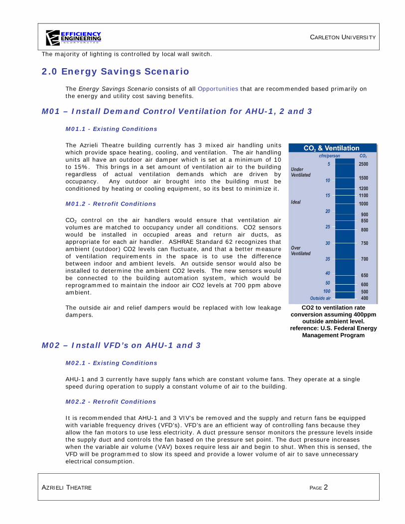
CARLETON UNIVERSITY
AZRIELI THEATRE PAGE 2
The majority of lighting is controlled by local wall switch.
2.0 Energy Savings Scenario
The Energy Savings Scenario consists of all Opportunities that are recommended based primarily on the energy and utility cost saving benefits.
M01 – Install Demand Control Ventilation for AHU-1, 2 and 3
M01.1 - Existing Conditions
The Azrieli Theatre building currently has 3 mixed air handling units which provide space heating, cooling, and ventilation. The air handling units all have an outdoor air damper which is set at a minimum of 10 to 15%. This brings in a set amount of ventilation air to the building regardless of actual ventilation demands which are driven by occupancy. Any outdoor air brought into the building must be conditioned by heating or cooling equipment, so its best to minimize it.
M01.2 - Retrofit Conditions
CO2 control on the air handlers would ensure that ventilation air volumes are matched to occupancy under all conditions. CO2 sensors would be installed in occupied areas and return air ducts, as appropriate for each air handler. ASHRAE Standard 62 recognizes that ambient (outdoor) CO2 levels can fluctuate, and that a better measure of ventilation requirements in the space is to use the difference between indoor and ambient levels. An outside sensor would also be installed to determine the ambient CO2 levels. The new sensors would be connected to the building automation system, which would be reprogrammed to maintain the indoor air CO2 levels at 700 ppm above ambient.
The outside air and relief dampers would be replaced with low leakage dampers.
M02 – Install VFD’s on AHU-1 and 3
M02.1 - Existing Conditions
AHU-1 and 3 currently have supply fans which are constant volume fans. They operate at a single speed during operation to supply a constant volume of air to the building.
M02.2 - Retrofit Conditions
It is recommended that AHU-1 and 3 VIV’s be removed and the supply and return fans be equipped with variable frequency drives (VFD’s). VFD’s are an efficient way of controlling fans because they allow the fan motors to use less electricity. A duct pressure sensor monitors the pressure levels inside the supply duct and controls the fan based on the pressure set point. The duct pressure increases when the variable air volume (VAV) boxes require less air and begin to shut. When this is sensed, the VFD will be programmed to slow its speed and provide a lower volume of air to save unnecessary electrical consumption.
CO2 to ventilation rate conversion assuming 400ppm
outside ambient level. reference: U.S. Federal Energy
Management Program

CARLETON UNIVERSITY
AZRIELI THEATRE PAGE 3
M03 – Reschedule All Air Handling Units
M03.1 - Existing Conditions
The building’s main air handling units supply heating cooling and ventilation to the spaces. They currently operate for long hours, regardless of whether or not the spaces are scheduled to be occupied. The units currently operate for 16-18 hours per day, seven days a week. The operating schedules, once set, do not get re-set on a regular basis to reflect actual building occupancy.
M03.2 - Retrofit Conditions
We recommend that the air handlers be scheduled on a weekly or monthly schedule to operate in a closer relation to the building’s actual occupancy schedule. Shutting the air handling units off when their respective spaces are unoccupied reduces electrical consumption due to fan operation as well as steam consumption due to air infiltration.
M04 – Lighting Controls: Occupancy Sensors
M04.1 - Existing Conditions
Lighting is primarily controlled by local wall switch. Many lights are left on when rooms remain unoccupied. Corridors and Boiler Room are typically left on 24/7.
M04.2 - Retrofit Conditions
We recommend installing occupancy sensors in many of the offices, corridors, washrooms and storage rooms. Typical energy savings range from 30%-60%, depending on the pattern and frequency of room use. It is important that qualified contractors are familiar with all building code and by law requirements regarding the installation of occupancy sensors, lighting level requirements and fire code. Safety of occupants should always be addressed when determining suitable applications for occupancy sensors.
M05 – Lighting Upgrade: T8 High Performance System
M05.1 - Existing Conditions
Linear fluorescent fixtures throughout the building house a mixture of T12 and T8 lamps in combination with inefficient magnetic ballasts. As the magnetic ballasts sporadically fail they are being replaced with electronic ballasts.
M05.2 - Retrofit Conditions
We recommend retrofitting existing fixtures housing magnetic ballasts with reduced wattage (25w) lamps and high efficiency electronic ballasts. A high performance retrofit achieves 37% savings over the existing T8 system and 49% savings over the existing T12 system.
July 1, 2010 saw the ban of magnetic ballast production in Canada. This includes the large majority of T12 and T8 magnetic ballasts. This means that when a magnetic ballast fails it must be replaced with an electronic ballast. There are many benefits to changing to electronic ballasts, well beyond the improved efficiency. Total Harmonic Distortion (THD) is greatly reduced. The “flicker” and “hum” that magnetic systems are notoriously known for are greatly reduced. Electronic ballasts have longer average life spans, improve lamp life and because they can drive up to 4 lamps versus just 1 or 2 lamps, and they create less waste.

CARLETON UNIVERSITY
AZRIELI THEATRE PAGE 4
M06 – Water Conservation: Install Ultra Low Flow 0.5 gpm Faucet Aerators
M06.1 - Existing Conditions
Water faucets throughout the building are currently equipped with standard 2.2 gallons per minute (gpm) aerators in the washrooms.
M06.2 - Retrofit Conditions
We recommend installing ultra low flow faucet aerators on all existing faucets with 2.2 gpm aerators. These ultra low flow aerators supply hand sanitation at a much lower flow rate at 0.5 gpm.
M07 – Fully Integrated Lighting Controls (BAS or Stand Alone)
M07.1 - Existing Conditions
Many of the building’s offices, classrooms and storage rooms are being controlled by local wall switches. In many cases lights remain on longer than the space is occupied.
M07.2 - Retrofit Conditions
An efficient integrated lighting control system should take advantage of savings through time scheduling, daylight harvesting, task tuning, occupancy control, personal control and variable load shedding. Combined effectively, these methods can result in 50-75% energy savings.
To achieve maximal energy savings an effective integrated lighting control system should provide: • a user friendly interface that would allow on site staff to control lighting throughout the entire
facility using a point and click set up (interface can be on a network PC system or web-based for ultimate control for future portfolio monitoring and control)
• the ability to adjust settings, limits, and time schedules on event specific, daily, weekly, or monthly basis
• allow for interface with HVAC and Security control systems and equipment to share data such as occupancy status and adjust for status
• allow monitoring of occupancy sensors, dimmers and wall switches to enable zones to be configured such that only the fixtures in that entrance and exit pathway or area shall be left on.
• allow for personal settings to be adjusted and set for specific fixtures or group of fixtures. This can increase productivity as it ensures that individuals can select the amount of light that best enables them to perform a task.
• the ability to illustrate and report consumption, light levels, light status, power density, and occupancy status help ensure that the system is being effectively utilized while also having the added benefit of simple assurance that all individuals have vacated the facility.
We recommend that a high performance integrated lighting control system meeting the above criteria be installed.

CARLETON UNIVERSITY
AZRIELI PAVILION PAGE 1
1.0 Azrieli Pavilion (#32) - Existing Building Profile
The facility is a 49,496 ft2 building containing four large auditoriums and some office spaces
Heating
Heat to the building is provided by the campus’ centralized steam plant via steam to hot water heat exchangers. Hot water from the heat exchanger then supplies perimeter heating as well as the heating coil in the building’s main handling unit.
Domestic Hot Water (DHW)
Domestic hot water to the facility is supplied by small individual electric hot water heater tanks located in various areas near their respective points of consumption.
Cooling
The entire facility is supplied with air conditioning through chilled water coils in the building’s air handling units.
Chilled water is supplied by a chilled water plant located in another building.
Specific areas of the building are equipped with cooling only heat pumps. Cooling for the heat pump loop is provided by a rooftop mounted chiller.
Ventilation
Azrieli Pavilion is supplied with ventilation from the building’s main air handling unit, AHU-1 located on the building’s rooftop. It is equipped with a heating coil and chilled water coil for conditioning supply air. The unit is equipped with a VFD.
Water Fixtures
Water fixtures at the facility consist primarily of low flow flushometer toilets and urinals as well as washroom sinks with aerators. No running/leaking fixtures or damaged aerators were observed.
Lighting
Most lighting throughout the facility has been upgraded to higher efficiency lamps and fixtures. Linear florescent lighting throughout offices, classrooms, corridors, stairwells and common spaces consisted of efficient T8 lamps with electronic ballasts. Some office and storage areas of this facility have been upgraded with occupancy sensors. Pot light fixtures were equipped with compact florescent lamps. The majority of
AHU-1, Serves Entire
Electric Heater Tank, Newer, In Good Operating Condition
Rooftop Chiller

CARLETON UNIVERSITY
AZRIELI PAVILION PAGE 2
lighting is controlled by local wall switch.
2.0 Energy Savings Scenario
The Energy Savings Scenario consists of all Opportunities that are recommended based primarily on the energy and utility cost saving benefits.
M02 – Implement “Partial Occupancy” Schedule on AHU-1
M02.1 - Existing Conditions
Ventilation to the building is provided by one mixed air handling unit. This unit brings in fixed amounts of outdoor air and blends it with return air before returning it to the space. Any outdoor air brought into the building must be heated or cooled by the building’s HVAC systems, so it’s best to minimize it.
The AHU brings in a variable amount of outdoor air based on outdoor and supply air temperatures. The minimum amount of outdoor air being brought in by a particular AHU is controlled by the minimum outdoor air damper position set at the BAS. Typically, the minimum ventilation level (minimum outdoor air damper position), would be set to provide adequate ventilation during times of peak occupancy (fully occupied hours). Any outside air brought into the building has to be conditioned by heating or cooling equipment, so it is best to minimize it.
Currently, the air handling unit operates seven days per week, 365 days per year. It typically operates from 7 in the morning through until 11 at night with slightly reduced hours on weekends. During these hours of operation, the unit is bringing in ventilation air at a rate based on the minimum outdoor air damper position (10%). This minimum ventilation rate is typically based on the expected normal peak occupancy of the building.
The building is primarily used as large auditoriums and some office spaces with peak occupancy occurring during normal business hours, Monday-Friday from 8am to 5pm. Occupancy during early morning, late evening and weekend periods is drastically lower. Currently, however, the AHU continues to bring in large amounts of ventilation air during these times of “partial occupancy”.
M02.2 - Retrofit Conditions
We recommend implementing a “Partial Occupancy” schedule to reduce the amount of fresh air supplied during times of lower occupancy (evenings, weekends, during extended breaks). The existing Occupied/Unoccupied schedule for the AHU’s will be updated to include a “Partial Occupancy” schedule at the beginning and end of each day as well as over weekends and during summer and winter breaks as appropriate. During the scheduled “Partial Occupancy” hours, the minimum outdoor air damper position will be reset to a lower value than the current occupied hours minimum to reflect the greatly reduced occupancy loads. This will reduce unnecessary amounts of outdoor air needing to be conditioned. Implementation costs for this measure are relatively low for the scheduling. As all of the controls exist, only updating of the building automation system would be required.
M03 – Campus Wide Integrated Lighting Controls
M03.1 - Existing Conditions
Many of the building’s offices and auditoriums are being controlled by local wall switches. In many cases lights remain on longer than the space is occupied.

CARLETON UNIVERSITY
AZRIELI PAVILION PAGE 3
M03.2 - Retrofit Conditions
An efficient integrated lighting control system should take advantage of savings through time scheduling, daylight harvesting, task tuning, occupancy control, personal control and variable load shedding. Combined effectively, these methods can result in 50-75% energy savings.
To achieve maximal energy savings an effective integrated lighting control system should provide: • a user friendly interface that would allow on site staff to control lighting throughout the entire
facility or campus using a point and click set up (interface can be on a network PC system or web-based for ultimate control for future portfolio monitoring and control)
• the ability to adjust settings, limits, and time schedules on event specific, daily, weekly, or monthly basis
• allow for interface with HVAC and Security control systems and equipment to share data such as occupancy status and adjust for status. This type of system would allow individuals to immediately identify which areas of a building or campus are occupied at what hours, providing additional information to security personnel.
• allow monitoring of occupancy sensors, dimmers and wall switches to enable zones to be configured such that only the fixtures in that entrance and exit pathway or area shall be left on.
• allow for personal settings to be adjusted and set for specific fixtures or group of fixtures. This can increase productivity as it ensures that individuals can select the amount of light that best enables them to perform a task.
• the ability to illustrate and report consumption, light levels, light status, power density, and occupancy status help ensure that the system is being effectively utilized while also having the added benefit of simple assurance that all individuals have vacated the facility.
We recommend that a high performance integrated lighting control system meeting the above criteria be installed campus wide.
As electrical rates and time of use charges increase, it is becoming more critical that energy savings are achieved not only by installing efficient lighting but by controlling the way and time of use lighting is utilized.

CARLETON UNIVERSITY
HVI&VS BUILDING PAGE 1
1.0 Human Computer Interaction (#37) and Visualization & Simulation Building (#38) - Existing Building Profile
Both buildings with total floor area of 97,271 ft2 serve primarily as offices along with some classroom and auditorium space.
Heating
Heat to the building is provided by the campus’ centralized steam plant via shell and tube heat exchangers. Hot water from these heat exchanger supplies hot water coils in the building’s two main air handling units as well as some perimeter heating.
Domestic Hot Water (DHW)
Domestic hot water to the facility is supplied by a heat exchanger which draws from the University’s centralized steam plant for pre-heat, and is then “topped up” by an electric heater tank.
Cooling
The entire facility is supplied with air conditioning.
It is equipped with a single chiller and a cooling tower which supply chilled water to the building’s two main air handling units. There are also two air cooled condensors which serve the heat pumps for the server room.
Ventilation
The Human Computer Interaction building is supplied with ventilation from the building’s two main air handling units. Each AHU is equipped with a hot water and a chilled water heating coil to provide conditioned air as well as ventilation throughout the building.
CO2 levels are monitored by the BAS however the ventilation rates are controlled by to minimum levels according to an occupancy schedule. The supply fans on both AHU’s are equipped with VFD’s.
Water Fixtures
Water fixtures at the facility consist of low flow flushometer toilets and kitchen and washroom sinks with aerators. No running/leaking fixtures or damaged aerators were observed.
Lighting
Linear florescent lighting throughout the two buildings consists of efficient T8 lamps with electronic ballasts. Pot light fixtures were equipped with compact fluorescent lamps. The elevator in the Human Computer Interaction building still houses T12 lamps and magnetic ballasts. Exit signs are LED.

CARLETON UNIVERSITY
HVI&VS BUILDING PAGE 2
2.0 Energy Savings Scenario
The Energy Savings Scenario consists of all Opportunities that are recommended based primarily on the energy and utility cost saving benefits.
M01 – Install VFD’s on P-1 and 2, Open Balancing Valves on Pumps and Chiller
M01.1 - Existing Conditions
The pumps P-1 and 2 currently serve the chilled water plant as the main distribution return pumps. They maintain a single pump speed when there is a demand for chilled water to be circulated on warmer days when the building must be cooled. The pumps are currently throttled down using valves which are approximately 60% open.
M01.2 - Retrofit Conditions
It is recommended that the valves be opened to 100% and these two pumps be equipped with VFD’s to give them the ability to modulate their flow based on the demand from the buildings HVAC equipment. By modulating the speed of the pumps with a VFD and allowing them to control the flow, a lower electrical consumption can be achieved.
M02 – Install VFD’s on P-5 and 6, Open Balancing Valves on Pumps and Chiller
M02.1 - Existing Conditions
The pumps P-5 and 6 currently serve the chilled water plant as the condenser (cooling tower) circulators. They maintain a single pump speed when there is a demand for condenser water to be circulated on warmer days when the building must be cooled. The pumps are currently throttled down using ball valves which are approximately 60% open. Throttling the flow using valves results in increased pressure drops through the system and causes the pumps to consume more electrical energy than is required.
M02.2 - Retrofit Conditions
It is recommended that the valves be opened to 100% and these two pumps be equipped with VFD’s to give them the ability to modulate their speed based on the demand from the building’s HVAC equipment. By modulating the speed of the pumps with a VFD and allowing them to control the flow, a lower electrical consumption can be achieved.
M03 – Open Balancing Valves on P-3 and 4 to AHU-1 and 2 Cooling Coils
M03.1 - Existing Conditions
The pumps P-3 and 4 currently serve the chilled water plant as the main distribution supply pumps. They are equipped with VFD’s but throttled with valves set approximately 60% open. Throttling the flow using valves results in increased pressure drops through the system and causes the pumps to consume more electrical energy than is required.

CARLETON UNIVERSITY
HVI&VS BUILDING PAGE 3
M03.2 - Retrofit Conditions
It is recommended that the valves be opened to 100% and the flow controlled by the existing pump VFD’s. By modulating the speed of the pumps with the existing VFD’s and allowing the drives to fully control the flow, a lower electrical consumption can be achieved.
M05 – Open Balancing Valves on P-7 and 8, Control Flow with Existing VFD’s
M05.1 - Existing Conditions
The pumps P-7 and 8 currently serve the two air cooled condensers as the main distribution supply pumps for the data centre cooling. They are equipped with VFD’s but throttled with ball valves set approximately 60% open. Throttling the flow using valves results in increased pressure drops through the system and causes the pumps to consume more electrical energy than is required.
M05.2 - Retrofit Conditions
It is recommended that the valves be opened to 100% and the flow controlled by the existing pump VFD’s based on the demand for cooling. By modulating the speed of the pumps with a VFD and allowing the drives to fully control the flow, a lower electrical consumption can be achieved.
M06 – Implement “Partial Occupancy” Schedule on AHU’s-1 and 2
M06.1 - Existing Conditions
Ventilation to the building is provided by two mixed air handling units. These units bring in fixed amounts of outdoor air and blend it with return air before returning it to the space. Any outdoor air brought into the building must be heated or cooled by the building’s HVAC systems, so it’s best to minimize it.
The AHU’s bring in a variable amount of outdoor air based on outdoor and supply air temperatures. The minimum amount of outdoor air being brought in by a particular AHU is controlled by the minimum outdoor air damper position set at the BAS. Typically, the minimum ventilation level (minimum outdoor air damper position), would be set to provide adequate ventilation during times of peak occupancy (fully occupied hours). Any outside air brought into the building has to be conditioned by heating or cooling equipment, so it is best to minimize it.
Currently, the air handling units operate seven days per week, 365 days per year. They typically operate from 6-7 in the morning through until 8-9 at night with slightly reduced hours on weekends. During these hours of operation, the units are bringing in ventilation air at a rate based on the minimum outdoor air damper position (15-25%). This minimum ventilation rate is typically based on the expected normal peak occupancy of the building.
The building is primarily used as office space with peak occupancy occurring during normal business hours, Monday-Friday from 8am to 5pm. Occupancy during early morning, late evening and weekend periods is drastically lower. Currently, however, the AHU’s continue to bring in large amounts of ventilation air during these times of “partial occupancy”.

CARLETON UNIVERSITY
HVI&VS BUILDING PAGE 4
M06.2 - Retrofit Conditions
We recommend implementing a “Partial Occupancy” schedule to reduce the amount of fresh air supplied during times of lower occupancy (evenings, weekends, during extended breaks). The existing Occupied/Unoccupied schedule for the AHU’s will be updated to include a “Partial Occupancy” schedule at the beginning and end of each day as well as over weekends and during summer and winter breaks as appropriate. During the scheduled “Partial Occupancy” hours, the minimum outdoor air damper position will be reset to a lower value than the current occupied hours minimum position to reflect the greatly reduced occupancy loads. This will reduce unnecessary amounts of outdoor air needing to be conditioned. Implementation costs for this measure are relatively low for the scheduling. As all of the controls exist, only updating of the building automation system would be required.
M07 – Lighting Upgrade: T8 High Performance System
M07.1 - Existing Conditions
The elevator in the Human Computer Interaction building still houses T12 linear fluorescent lamps with magnetic ballasts.
M07.2 - Retrofit Conditions
We recommend retrofitting existing T12 fixtures with reduced wattage (25w) T8 lamps and high efficiency electronic ballasts. A high performance retrofit achieves 40% savings over the existing system.
July 1, 2010 saw the ban of magnetic ballast production in Canada. This includes the large majority of T12 and T8 magnetic ballasts. This means that when a magnetic ballast fails it must be replaced with an electronic ballast. There are many benefits to changing to electronic ballasts, well beyond the improved efficiency. Total Harmonic Distortion (THD) is greatly reduced. The “flicker” and “hum” that magnetic systems are notoriously known for are greatly reduced. Electronic ballasts have longer average life spans, improve lamp life and because they can drive up to 4 lamps versus just 1 or 2 lamps, and they create less waste.
M08 – Lighting Controls: Install Occupancy Sensors
M08.1 - Existing Conditions
Lighting is primarily controlled by local wall switch. Many lights are left on when rooms remain unoccupied. Corridors are typically left on 24/7.
M08.2 - Retrofit Conditions
We recommend installing occupancy sensors in many of the offices, classrooms, corridors, and storage rooms. Typical energy savings range from 30%-60%, depending on the pattern and frequency of room use. It is important that qualified contractors are familiar with all building code and by law requirements regarding the installation of occupancy sensors, lighting level requirements and fire code. Safety of occupants should always be addressed when determining suitable applications for occupancy sensors.

CARLETON UNIVERSITY
HVI&VS BUILDING PAGE 5
M09 – Water Conservation: Install Ultra Low Flow 0.5 gpm Faucet Aerators
M09.1 - Existing Conditions
Water faucets throughout the building are currently equipped with standard 2.2 gallon per minute (gpm) aerators in the washrooms.
M09.2 - Retrofit Conditions
We recommend installing ultra low flow faucet aerators on all existing faucets with 2.2 gpm aerators. These ultra low flow aerators supply hand sanitation at a much lower flow rate at 0.5 gpm.
M10 – Campus Wide Integrated Lighting Controls
M10.1 - Existing Conditions
Lighting is primarily controlled by local wall switch. Many lights are left on when areas remain unoccupied or in areas where adequate natural light is illuminating the area. Corridors are typically left on 24/7.
M10.2 - Retrofit Conditions
An efficient integrated lighting control system should take advantage of savings through time scheduling, daylight harvesting, task tuning, occupancy control, personal control and variable load shedding. Combined effectively, these methods can result in 50-75% energy savings.
To achieve maximal energy savings an effective integrated lighting control system should provide:
• a user friendly interface that would allow on site staff to control lighting throughout
the entire facility or campus using a point and click set up (interface can be on a network PC system or web-based for ultimate control for future portfolio monitoring and control)
• the ability to adjust settings, limits, and time schedules on event specific, daily, weekly, or monthly basis
• allow for interface with HVAC and Security control systems and equipment to share data such as occupancy status and adjust for status. This type of system would allow individuals to immediately identify which areas of a building or campus are occupied at what hours, providing additional information to security personnel.
• allow monitoring of occupancy sensors, dimmers and wall switches to enable zones to be configured such that only the fixtures in that entrance and exit pathway or area shall be left on.
• allow for personal settings to be adjusted and set for specific fixtures or group of fixtures. This can increase productivity as it ensures that individuals can select the amount of light that best enables them to perform a task.
• the ability to illustrate and report consumption, light levels, light status, power density, and occupancy status help ensure that the system is being effectively utilized while also having the added benefit of simple assurance that all individuals have vacated the facility.

CARLETON UNIVERSITY
HVI&VS BUILDING PAGE 6
We recommend that a high performance integrated lighting control system meeting the above criteria be installed campus wide. As electrical rates and time of use charges increase, it is becoming more critical that energy savings are achieved not only by installing efficient lighting but by controlling the way and time of use lighting is utilized.
3.0 Longer Payback Scenario
The Longer Payback Scenario consists of Opportunities that are not as financially attractive as the Energy Savings Scenario. These measures should be considered when equipment failure occurs or as Capital Renewal projects as equipment reaches its end of life.
M04 – Install VFD on Cooling Tower Fan
M04.1 - Existing Conditions
The building has two cross flow cooling towers which help the condenser water to cool off. The fan which draws this air though the tower is a 15 hp axial fan which runs on a 2 speed motor with a high and low speed. The speed of the fan is controlled by the condenser supply temperature based on the set point on the BAS.
M04.2 - Retrofit Conditions
It is recommended that the 15 hp fan from CT-01 be equipped with a VFD to control the speed of the tower fan based on the condenser supply temperature. The VFD will modulate the speed of the fan and allow it to run at a wider range of speeds, resulting in a lower consumption of electricity.