Energy, Environment & Efficiency Measures of Bagasse … enhancement, a case study.pdf ·...
33
By, Mohammad Sarfaraz Khan DGM (Technical) Faran Sugar Mills Limited Shaikh Bhirkio, District Tando Mohammad Khan, Sindh. By, Mohammad Sarfaraz Khan DGM (Technical) Faran Sugar Mills Limited Shaikh Bhirkio, District Tando Mohammad Khan, Sindh.
Transcript of Energy, Environment & Efficiency Measures of Bagasse … enhancement, a case study.pdf ·...

By,
Mohammad Sarfaraz KhanDGM (Technical)
Faran Sugar Mills LimitedShaikh Bhirkio,
District Tando Mohammad Khan, Sindh.
By,
Mohammad Sarfaraz KhanDGM (Technical)
Faran Sugar Mills LimitedShaikh Bhirkio,
District Tando Mohammad Khan, Sindh.

1. Faran Sugar Mills commissioned during 1983 with twobagasse-fired boilers of FCB design had initial evaporationcapacity of 34 TPH @ 24Kg/cm2, 3300 C as designed workingparameters.
2. Initially both boilers were supplied with economizers assole heat recovery units without air-heater and ashcollecting arrangement.
3. In order to attain efficiency and further capacityenhancement, a well designed road map has been preparedto ascertain desired modifications/implementations at FCBboiler # 2 during off – season 2011 .
4. However, we had raised the generation capacity of Boiler #1 from 34 – 38 TPH in a first phase during off - season 2009and further to 40 TPH along with boiler # 2 in the secondphase.
2

Certain parts like economizer ( Sole –heat recovery unit) needed to be replaced
due to its under rated efficiency. , As a result the temperature of out going gases
was increased in stack between 300 – 310 ˚C Inspite of design 254 ˚C.
Poor thermal efficiency due to higher stack loss.
Operational inconsistencies
Operating the boiler was a difficult exercise, because of heap firing of bagasse in
the furnace instead of suspended combustion due to non-availability of air heater
hot air.
Furnace backing was also a problem for boiler and was a safety hazard for the
operators on site.
Persisting ID Fan after the season’s campaign reflects badly wearing
of impeller parts.
3

Due to non –availability of Ash – collecting system, particleswere discharging from the stack and creatingenvironmental problem.
Besides eroding the areas including, Economizer tubes,Ducting, this caused an involuntary violation of local EPArules as well.
Assessment regarding metal loss due to non-availability ofash collecting system on economizer tube surfaces,ducting, Fans integrals proportional to 2.5th exponent oflinear velocity of gases really in the hazardous zone.
Plant requirement seeks for capacity enhancement tomeets the steam needs regarding higher crushing rates.
4

Steam generation capacity of any solid fuel boiler mainlydepends upon its heating surface, grate area, furnacevolume and draft system
There were number of proposals which remained underdiscussion for capacity enhancement are as follows,
Extension of tube height through relocation of drums for
additional heating surface.
Furnace wall relocation to increase furnace area andvolume as well.
After, certain discussions, home work & ground realities wehad choice expansion without disturbing the drum heightand furnace wall due to Furnace area/volume assessment,were sufficient to generate 40 TPH capacity.
(Furnace Area 21.9 M2 , Furnace Volume 148 M3)
Steam generation capacity of any solid fuel boiler mainlydepends upon its heating surface, grate area, furnacevolume and draft system
There were number of proposals which remained underdiscussion for capacity enhancement are as follows,
Extension of tube height through relocation of drums for
additional heating surface.
Furnace wall relocation to increase furnace area andvolume as well.
After, certain discussions, home work & ground realities wehad choice expansion without disturbing the drum heightand furnace wall due to Furnace area/volume assessment,were sufficient to generate 40 TPH capacity.
(Furnace Area 21.9 M2 , Furnace Volume 148 M3)5

In this connection, we have incorporated additional designedpressure parts and allied accessories to ascertain the capacityenhancement such as,
Additional Roof header of 273 diameter X 25.4 (T) X 5790 (L) MM
Additional 30 numbers of generation tubes of 76.1 MM diameterwhich connected between steam drum & Front header throughincorporated roof header along with previous 31 tubes (Total 61numbers)
Additional 40 numbers of generation tubes of 76.1 MM diameter atboth locations (20 Each) of side headers.
Additional 02 numbers of Upper Risers of 76.1 MM diameter whichconnected between steam drum & side headers from top.
Five newly fabricated super heater coils were installed to raise itsquantity from 55 to 60 of 38.1 diameter X 3.2 (thickness) X 15000MM length.
6

Economizer redesigned with additional heatingsurface from 45 to 145 M2 . This additional heatingsurface possibility facilitated by larger air heaterspace.
Air Heater induction of 900 M2 heating surface
Well designed Ash Collecting system to meets 40 TPHboiler producing ash.
All draft fans changed with new fans to bear theadditional load due to addition of air heater,economizer and dust collector . Additionally, ductingreplaced to suit the new fans.
Chimney height increased up to 100 feet from 70 feetto facilitate draft.
7

1132
Description Previous Enhanced Rise Rise % Status
Furnace Radiation 251 378 127 33.60 Furnace/Riser
Over all Boiler 1005 1132 127 11.22 Total
Super Heater 74 81 7 8.64 Elements
Air Heater NA 900 900 100 Heat Recovery
Economizer 45 145 100 68.97 Heat Recovery
251
1005
74
0
45
378
1132
81
900
145
127
127
7
900
100
33.6
0
11.2
2
8.64
100
68.9
7
0
200
400
600
800
1000
1200
Furnace Radiation Over all Boiler Super Heater Air Heater Economizer
Previous
Enhanced
Rise
Rise %
8

9

Dust collector arrangement designed, fabricated anderected to meets the ash production disposal on 5 %based of fuel consumption at MCR.
However, it is further translates to 909 Kg/hr of ash @18181Kg/hr of bagasse consumption.
44 numbers of cyclones installed to capture the ash.
Two numbers rotary valves use to handle theproducing ash.
10

11
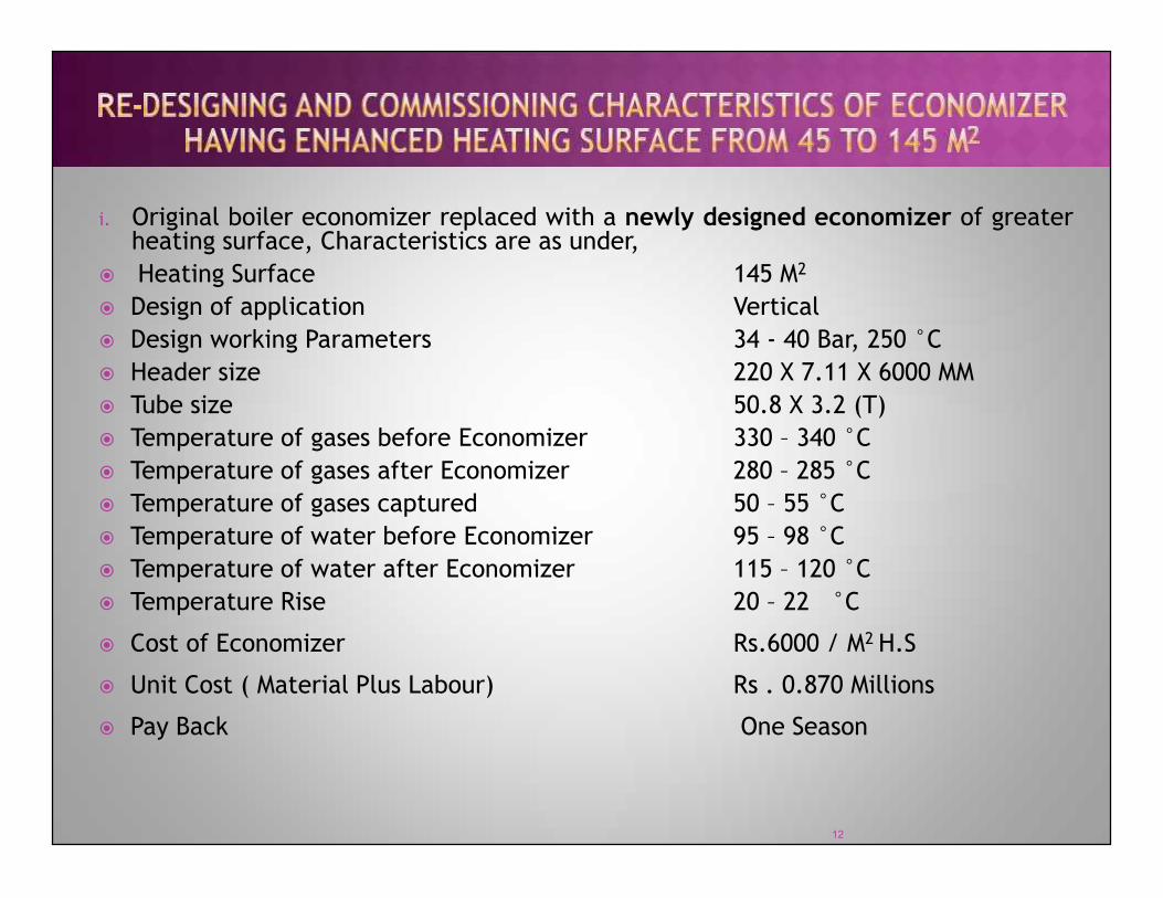
i. Original boiler economizer replaced with a newly designed economizer of greaterheating surface, Characteristics are as under,
Heating Surface 145 M2
Design of application Vertical Design working Parameters 34 - 40 Bar, 250 °C Header size 220 X 7.11 X 6000 MM Tube size 50.8 X 3.2 (T) Temperature of gases before Economizer 330 – 340 °C Temperature of gases after Economizer 280 – 285 °C Temperature of gases captured 50 – 55 °C Temperature of water before Economizer 95 – 98 °C Temperature of water after Economizer 115 – 120 °C Temperature Rise 20 – 22 °C
Cost of Economizer Rs.6000 / M2 H.S
Unit Cost ( Material Plus Labour) Rs . 0.870 Millions
Pay Back One Season
12

13

ii. A new FCB- design air heater of appropriate specification has been designedand installed. Their characteristics are as follows,
Heating Surface 900 M2
Stack out going gas temperature before Air-heater 280 – 285 °C
Stack out going gas temperature after Air-heater 196 - 220 °C
Air heater out let air temperature 135 –151 °C
Ambient air temperature 20 – 30 °C
14

15

16

Description Achieved Designed
Temperature of gases before Economizer 330 – 340 °C 325
Temperature of gases after Economizer 280 – 285 °C 285
Temperature of water before Economizer 95 – 98 °C 98
Temperature of water after Economizer 115 – 120 °C 115-120
Stack out going gas temperature before Air-heater 280 – 285 °C 285
Stack out going gas temperature after Air-heater 196 - 220 °C 160 -200
Air heater out let air temperature 135 –151 °C 170 -190
Ambient air temperature 20 – 30 °C 25
17

325
285
98
120
285
180
180
25
330
280
98
120
285
208
145
303550
100
150
200
250
300
350
25 30
-5
5 0 0 0
-28
35
-5
-50
0
50
Tem
pera
ture
of
gase
s be
fore
Eco
nom
izer
Tem
pera
ture
of
gase
s af
ter
Econ
omiz
er
Tem
pera
ture
of
wat
er b
efor
e Ec
onom
izer
Tem
pera
ture
of
wat
er a
fter
Eco
nom
izer
Stac
k ou
t go
ing
gas
tem
pera
ture
bef
ore
Air-
heat
er
Stac
k ou
t go
ing
gas
tem
pera
ture
aft
er A
ir-h
eate
r
Air
heat
er o
ut le
t ai
r te
mpe
ratu
re
Ambi
ent
air
tem
pera
ture
Designed
Achieved
Variance
18

DESCRIPTION BEFORE MODIFICATION(DESIGNED)
AFTER MODIFICATIONINSTALLED WITH VFD
ID Fan motor power 110 KW 250 KW
FD Fan motor 25 KW 110 KW
SA Fan Motor 22 KW 45 KW
Total Power 157 KW 405 KW
Excess Power 248 KW
19

1. Temperature of out going Gases to stack restricted withinrange of 196 – 220 oC against 300-310 oC.
2. Boiler efficiency increased by 6.9 %
305
208
100
150
200
250
300
350
Stack Temperature ˚C
1. Temperature of out going Gases to stack restricted withinrange of 196 – 220 oC against 300-310 oC.
2. Boiler efficiency increased by 6.9 %0
50
Previous Reduced
66.9
4
73.8
4
6.9
0
10
20
30
40
50
60
70
80
Previous Enhanced Rise
Boiler Efficiency %
20

1. Boiler capacity enhanced to 6 TPH from,
34 40TPH.
40
4041
Capacity Enhancement (TPH)34
40
31323334353637383940
Rated Capacity Enhanced Capacity
21

1. Operational difficulties have been overcome to certain extent. Boiler isoperating smoothly, no backing and heap firing observed. Quality of flameremained satisfactory. Temperature around 950 - 1000oC achieved.
22

902
848
741
975
907
770
600
800
1000
1200
352
343
300
0 0
365
330
285
280
208
0
200
400
Furn
ace
out
let
Supe
r he
ater
inl
et
Tube
ban
k in
let
Tube
ban
k ou
tlet
Econ
omiz
er in
let
Econ
omiz
er o
utle
t
Air
Hea
ter
inle
t
Air
Hea
ter
outl
et
Previous
Existing
23

1. Dust - collector is working excellently thereby proving the apexcapacity of the installed equipment; one of the significant aspectsobserved was the quantity of ash carried over to stack alsocontrolled ,which is termed as eco-friendly.
2. Inspite of 248 KW excess power consumption, we have attainedan extra 6 TPH steam. Bagasse consumption has also reduced dueto increase in boiler efficiency.
3. ID Fan installed with improved material of Hardox – 500 whichhave significantly wear resistance against erosion.
4. Bagasse to Steam ratio improved from 1.81 1.99
5. Bagasse Consumption reduce 1.69 TPH for unit TPH of Steamgeneration.
6. Pay back 3 – 4 Years @ 4056 Tons of bagasse saving per season.
1. Dust - collector is working excellently thereby proving the apexcapacity of the installed equipment; one of the significant aspectsobserved was the quantity of ash carried over to stack alsocontrolled ,which is termed as eco-friendly.
2. Inspite of 248 KW excess power consumption, we have attainedan extra 6 TPH steam. Bagasse consumption has also reduced dueto increase in boiler efficiency.
3. ID Fan installed with improved material of Hardox – 500 whichhave significantly wear resistance against erosion.
4. Bagasse to Steam ratio improved from 1.81 1.99
5. Bagasse Consumption reduce 1.69 TPH for unit TPH of Steamgeneration.
6. Pay back 3 – 4 Years @ 4056 Tons of bagasse saving per season.24

25

26

37.7
4
38.4
1
38.3
8
38.0
2
33.2
6
38.5
0 40.6
2
39.5
4
38.5
4
38.3
1
34.5
1 36.5
1
33.0
2
38.0
8
38.8
6
38.2
4
38.4
8
38.6
1
36.5
2
38.2
1
39.4
8
38.1
0 40.5
3
37.6
6
30.00
35.00
40.00
45.00
29-Jan-12
0.00
5.00
10.00
15.00
20.00
25.00
1 2 3 4 5 6 7 8 9 10 11 12 13 14 15 16 17 18 19 20 21 22 23 24
27

38.6
7
38.4
0
36.7
9
38.2
8
36.5
7
38.0
3
37.1
3
36.9
0 37.5
2
36.8
7
36.9
8
39.1
0
39.9
9 40.5
3
40.4
6
40.1
4
37.00
38.00
39.00
40.00
41.00
30-Jan-12
36.7
9
36.0
0
35.9
8 36.5
7
36.9
0
35.1
7
35.2
5
36.8
7
34.5
0 35.1
7 35.6
5
36.9
8
36.0
2
31.00
32.00
33.00
34.00
35.00
36.00
37.00
1 2 3 4 5 6 7 8 9 10 11 12 13 14 15 16 17 18 19 20 21 22 23 24
28

40.2
5
40.5
2
39.9
9
38.0
2
36.2
8 37.9
9
37.9
5
36.9
3
37.4
3
37.7
6
36.7
9
35.5
8
31.8
4
32.5
2 34.4
2
35.5
0
35.9
1
35.3
8
36.6
0
37.0
4
36.2
6 38.8
4
37.5
8
38.1
1
30.00
35.00
40.00
45.00
31-Jan-12
0.00
5.00
10.00
15.00
20.00
25.00
1 2 3 4 5 6 7 8 9 10 11 12 13 14 15 16 17 18 19 20 21 22 23 24
29

Entire activities sum – up as follows,1. Capacity Enhancement within safe working limits.2. Improved Efficiency with operational consistency3. Justified Environment measures.
30
First of all I am thankful of Almighty Allah who gave us courage during the
entire activity. Here, I cannot forget the role of Late Mr. Raza Ali Khan (Ex-
Technical Adviser) & Mr. R.J. Suleri (General Manager) of Faran Sugar
Mills, both of them supported us incredibly to make completion of massive
BMRE activities & subsequent commissioning during season 2011-12. The
author is also grateful for the Management support and confidence. In the last
but not least, I am really appreciating the efforts & commitment of our technical
team who always contributed from the front. Therefore, cumulative efforts
facilitated us to reach towards targeted results.
First of all I am thankful of Almighty Allah who gave us courage during the
entire activity. Here, I cannot forget the role of Late Mr. Raza Ali Khan (Ex-
Technical Adviser) & Mr. R.J. Suleri (General Manager) of Faran Sugar
Mills, both of them supported us incredibly to make completion of massive
BMRE activities & subsequent commissioning during season 2011-12. The
author is also grateful for the Management support and confidence. In the last
but not least, I am really appreciating the efforts & commitment of our technical
team who always contributed from the front. Therefore, cumulative efforts
facilitated us to reach towards targeted results.31

FCB Manual for bagasse fired boilers 34 TPH Boilers)
Design documents for up grading from 34 to 40 TPHFCB boiler
FSML Operational data for boilers( Season 2011 – 12)
Commissioning and season’s recorded data FSML.
Article entitled as Design & maintenance aspects forprevention of Pressure parts failure in sugar plantsteam generators by S. Sridharan
32

33