en-US 10013865-0ASDE-B instructions Combi Steamer Unit Type of energy Unit typeModel FlexiCombi...
80
Service instructions Combi Steamer Unit Type of energy Unit type Model FlexiCombi MagicPilot Electric Tabletop unit FKECOD61 5 FKECOD62 1 FKECOD11 5 FKECOD12 1 Pedestal unit FKECOD21 5 FKECOD22 1 Gas Tabletop unit FKGCOD6 15 FKGCOD6 21 FKGCOD1 15 FKGCOD1 21 Pedestal unit FKECOD21 5 FKECOD22 1 Translation from the original document • 10013865-0ASDE-B • 1/4/2017 10013865-0ASDE-B en-US REGISTER WARRANTY ONLINE AT WWW.HENNYPENNY.COM
Transcript of en-US 10013865-0ASDE-B instructions Combi Steamer Unit Type of energy Unit typeModel FlexiCombi...

Service instructions
Combi Steamer
Unit Type ofenergy
Unit type Model
FlexiCombiMagicPilot
Electric Tabletopunit
FKECOD615FKECOD621FKECOD115FKECOD121
Pedestalunit
FKECOD215FKECOD221
Gas Tabletopunit
FKGCOD615FKGCOD621FKGCOD115FKGCOD121
Pedestalunit
FKECOD215FKECOD221Tr
ansl
atio
n fro
m th
e or
igin
al d
ocum
ent •
100
1386
5-0A
SDE-
B • 1
/4/2
017
10013865-0ASDE-B en-USR E G I S T E R WA R R A N T Y O N L I N E AT W W W. H E N N Y P E N N Y. C O M

CopyrightAll rights to text, graphics and pictures in this documentation are held by MKN Maschinenfabrik KurtNeubauer GmbH & Co. KG. Distribution or duplication is exclusively permissible subject to a writtenconsent of MKN.Copyright by MKN Maschinenfabrik Kurt Neubauer GmbH & Co. KG
ManufacturerCopyright by MKN Maschinenfabrik Kurt Neubauer GmbH & Co. KGHalberstaedter Strasse 2aD-38300 WolfenbuettelTelephone 0 53 31 / 89-0Telefax 0 53 31 / 89-280
2 Service instructions

Directory of contents
3Service instructions
1 Password overview ............................................................ 7
2 Introduction ......................................................................... 82.1 About this manual ............................................................................ 82.2 Warranty ............................................................................................ 8
3 Safety instructions ............................................................. 9
4 Functional descriptions ................................................... 104.1 DynaSteam ...................................................................................... 104.2 WaveClean ...................................................................................... 11
5 Opening the appliance ..................................................... 135.1 Control panel .................................................................................. 13
6 Service menu - appliance test ......................................... 146.1 Service menu .................................................................................. 146.1.1 Calling up the service level ...................................................................... 146.1.2 Service menu overview ........................................................................... 146.2 Appliance information .................................................................... 156.3 Status information .......................................................................... 166.4 CombiDoctor ................................................................................... 196.5 Relay test ........................................................................................ 206.6 WaveClean Test .............................................................................. 226.7 100°C + core temperature calibration ........................................... 236.7.1 Checking the calibration - single-chamber appliance 6.x / 10.x .............. 246.7.2 Checking the calibration - two-chamber appliance 20.x .......................... 256.7.3 Calibrating the cooking chamber sensor - single-chamber appliance 6.x /10.x ................................................................................................................... 266.7.4 Calibrating the cooking chamber sensor - two-chamber appliance 20.x . 276.8 DynaSteam test .............................................................................. 286.9 Emptying the water ........................................................................ 296.10 Data and time ................................................................................ 296.11 Installation height ......................................................................... 306.12 Audio settings .............................................................................. 306.13 Select signal tones ....................................................................... 316.14 LOA activation (only for energy type electric) ........................... 316.15 Exporting log data ........................................................................ 316.16 Software update ........................................................................... 336.17 Importing additional content ....................................................... 336.18 Restoring data .............................................................................. 346.19 Backing up data ............................................................................ 346.20 Water filter maintenance .............................................................. 356.21 Importing contact data ................................................................. 35
1001
3865
-0AS
DE-
B

Directory of contents
4 Service instructions
6.22 Setting units .................................................................................. 366.23 Backup relay ................................................................................. 366.24 Settings parameters ..................................................................... 386.25 Status overview direct access .................................................... 40
7 Software ............................................................................ 417.1 Software update ............................................................................. 417.2 Importing additional content ......................................................... 437.3 Importing the manufacturer's cookbook ...................................... 45
8 Trade show mode ............................................................. 47
9 Electronics ........................................................................ 489.1 Overview of the controller ............................................................. 489.2 Layout of the control board ........................................................... 499.3 Configuration of the control board ............................................... 509.4 Safety overview ............................................................................. 53
10 Gas technology .............................................................. 5410.1 Basic principles ............................................................................ 54
11 Error messages .............................................................. 5511.1 Emergency operation ................................................................... 5511.2 Cooking chamber sensor defective (694, 695) .......................... 5611.3 Top cooking chamber sensor defective (696, 728) ................... 5711.4 Bottom cooking chamber sensor defective (697, 729) ............ 5811.5 Core temperature sensor defective (699, 700) ........................... 5911.6 Internal core temperature sensor defective (714, 716) ............. 6011.7 External core temperature sensor defective (715, 717) ............ 6011.8 Water vapor sensor defective (710) ............................................ 6111.9 Excess temperature in the cooking chamber (ID73) ................. 6211.10 Overtemperature control (TMP_ID2) ......................................... 6311.11 Critical temperature in the electronics (MMI_ID50) ................. 6311.12 Siphon temperature very high (SOF_ID20) .............................. 6311.13 Risk of frost (TMP_ID72, MMI_ID51) ......................................... 6311.14 Fan defective or temperature limiter triggered (702) .............. 6411.15 Fan defective. Cooking program was cancelled (701) ............ 6611.16 Top fan defective. Automatic switching to emergency operation(703, 705) ............................................................................................... 6611.17 Bottom fan defective. Automatic switching to emergencyoperation (704, 706) .............................................................................. 6711.18 Water pressure too low (709) .................................................... 6811.19 Faulty CAN connection .............................................................. 7011.20 Failure to access external EEPROM (SOF_ID)12 .................... 7011.21 Door is open - cooking program was stopped ........................ 70
1001
3865
-0AS
DE-
B

Directory of contents
5Service instructions
12 Gas faults and error messages ..................................... 7112.1 No gas (OTH_ID1) ......................................................................... 7112.2 No gas (top)(OTH_ID2) ................................................................. 7212.3 No gas (bottom)(OTH_ID3) .......................................................... 7212.4 No flame (OTH_ID4) ...................................................................... 7212.5 No flame (top)(OTH_ID5) .............................................................. 7212.6 No flame (bottom)(OTH_ID6) ....................................................... 7212.7 Communication fault between I/O and ignition electronics(OTH_ID25) ............................................................................................ 7312.8 Communication fault between I/O and ignition electronics (top)(OTH_ID26) ............................................................................................ 7312.9 Communication fault between I/O and ignition electronics(bottom) (OTH_ID27) ............................................................................ 7312.10 Checking the connection pressure .......................................... 7412.11 Checking the gas magnetic valve and gas heat exchanger ... 7512.12 Checking the electrodes ............................................................ 7612.12.1 Glow electrode .................................................................................... 7612.12.2 Ionization electrode ............................................................................. 77
1001
3865
-0AS
DE-
B
Directory of contents
6 Service instructions
1001
3865
-0AS
DE-
B

Password overview
7Service instructions
1 Password overviewRange Passw
ordDescription Described in
Installation /commissioning
2100 Setting all basic parameters(for example time / date).
Installationinstructions
CO2 gascalibration
999 Verification and calibration ofexhaust emissions. Only forenergy type - gas.
Installationinstructions
Network settings 2000 Input network addressing.Only for units withtouchscreen control.
Installationinstructions
Basic settings /user
111 Setting of basic values for theuser, functions, softwareupdate.
Operatinginstructions
Lockscreen 369 Deactivating the lockscreenin cooking mode. Only forunits with touchscreencontrol.
Operatinginstructions
Trade show mode 888 Activation / deactivation forexhibition mode.
Serviceinstructions
Service menu 1967 Service range for authorizedservice technicians.
Serviceinstructions
1001
3865
-0AS
DE-
B
Introduction
8 Service instructions
2 Introduction
2.1 About this manual
This service manual contains information needed by the servicetechnician for professional and correct fault isolation, repair andmaintenance of the unit. The service technician must also observethe contents of the installation instructions and the user manual.
Target group Target group for this service manual is qualified personnel who arefamiliar with the technical functioning and operation of the unit.
Figures All figures in this service manual are intended as examples.Discrepancies can arise between this and the actual unit.
Spare parts To ensure the reliability of the unit and the individual components, it isessential that only genuine OEM parts be used.Spare parts can be identified exactly with the aid of the onlinedatabase.
2.2 Warranty
The warranty is void and safety is no longer assured in the event of:
• Modifications or technical changes to the unit,
• Improper use,
• Incorrect startup, operation or maintenance of the unit,
• Problems resulting from failure to observe these instructions.
1001
3865
-0AS
DE-
B

Safety instructions
9Service instructions
3 Safety instructionsFor servicing tasks, the service technician must be familiar with andobserve regional regulations.In addition, the notes in the service manual must be observed.
DANGER Danger to life due to electric current
ü Disconnect power prior to performing gas and electrical work.
• Disconnect unit from the mains supply and secure it against restart.• Check to ensure absence of voltage.
DANGER Risk of fatal injury from gas
ü Disconnect the unit from gas supply prior to performing gas installationtasks.
• Lock site gas supply and secure it against restart.
1001
3865
-0AS
DE-
B

Functional descriptions
10 Service instructions
4 Functional descriptions
4.1 DynaSteam
Overview
a
b
c
d e
a Steaming appliance with pressureswitch
d Reduction
b Magnetic valve water vaporelimination
e Water supply pipe
c Heat exchanger (up to approx.50°degrees)
Description • The electronics control the DynaSteam steaming appliance. Theyregulate the water quantity for generating steam. DynaSteamguarantees, regardless of the water pressure, the precise supplyof the required quantity of water. The prerequisite for this is acustomer-supplied water flow pressure between 2 and 6 bar. Thewater pressure is monitored using a pressure switch.
• The DynaSteam steaming appliance cannot be calibrated and iscompletely electronically controlled.
• The heat exchange heats the water in advance up to 50°C. Theheat from the exhaust pipe is used for this.
• The water comes through the water supply pipe to the fan impellerin the cooking chamber. The fan impeller creates small waterdrops, which evaporate in the hot oven atmosphere. The waterevaporates in the cooking chamber and on the fan impeller. Thetapering of the hose stabilizes the water flow of the pulsingsteaming unit.
1001
3865
-0AS
DE-
B
Functional descriptions
11Service instructions
4.2 WaveClean
Functional overview
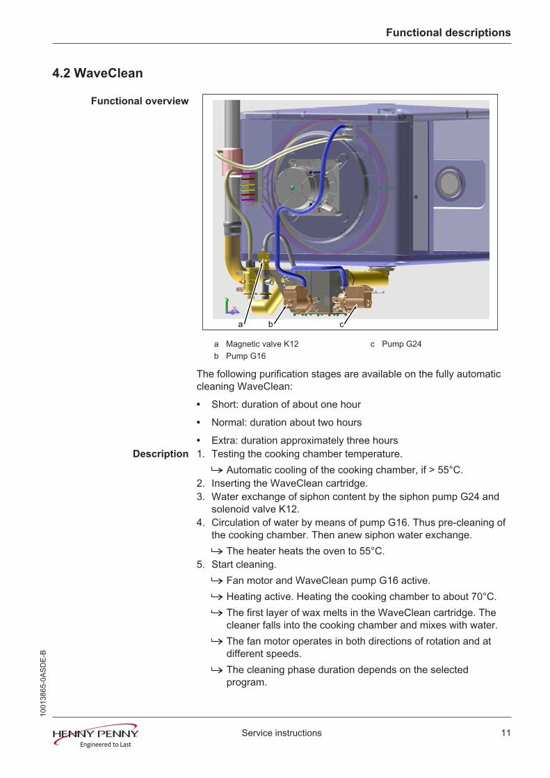
a b c
a Magnetic valve K12 c Pump G24b Pump G16
The following purification stages are available on the fully automaticcleaning WaveClean:
• Short: duration of about one hour
• Normal: duration about two hours
• Extra: duration approximately three hoursDescription 1. Testing the cooking chamber temperature.
Automatic cooling of the cooking chamber, if > 55°C.2. Inserting the WaveClean cartridge.3. Water exchange of siphon content by the siphon pump G24 and
solenoid valve K12.4. Circulation of water by means of pump G16. Thus pre-cleaning of
the cooking chamber. Then anew siphon water exchange.The heater heats the oven to 55°C.
5. Start cleaning.Fan motor and WaveClean pump G16 active.Heating active. Heating the cooking chamber to about 70°C.The first layer of wax melts in the WaveClean cartridge. Thecleaner falls into the cooking chamber and mixes with water.The fan motor operates in both directions of rotation and atdifferent speeds.The cleaning phase duration depends on the selectedprogram.
1001
3865
-0AS
DE-
B

Functional descriptions
12 Service instructions
6. A new water exchange of siphon content by means of the siphonpump G24 and solenoid valve K12.
7. Start of rinsing.Identical to step 5 (cleaning).Differences: Heating of the cooking chamber to 92°C. Thesecond layer of wax melts in the WaveClean cartridge. Therinse agent drops into the cooking chamber and mixes withwater.Final rinse to bring the pH value to the normal level.
8. In the programs "normal" and "extra" additional drying of theinterior occurs by means of hot air.
9. Finally, an indicator for withdrawing the WaveClean cartridgeappears, and has to be confirmed.
INFORMATION Despite different cleaning durations, all cleaning steps require the sameamount of water.During the cleaning process about 3 liters of water are provided by the steam-ing unit into the oven.
WaveClean termination
INFORMATION WaveClean forced rinsing
The WaveClean forced rinse is automatically started by the operator in case offailure or premature termination. The duration is 12 minutes. An entry is madeinto the HACCP and in the diagnostic memory.
1001
3865
-0AS
DE-
B
Opening the appliance
13Service instructions
5 Opening the appliance
5.1 Control panel
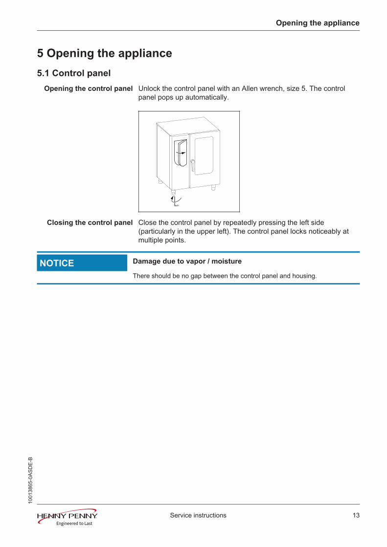
Opening the control panel Unlock the control panel with an Allen wrench, size 5. The controlpanel pops up automatically.
Closing the control panel Close the control panel by repeatedly pressing the left side(particularly in the upper left). The control panel locks noticeably atmultiple points.
NOTICE Damage due to vapor / moisture
There should be no gap between the control panel and housing.
1001
3865
-0AS
DE-
B

Service menu - appliance test
14 Service instructions
6 Service menu - appliance test
6.1 Service menu
Description • Functional testing of individual components
• Error analysis
• Maintenance
• Change basic settings
• Software update
The graphics shown may deviate due to changes and differentsoftware versions.
6.1.1 Calling up the service level
Calling up the Service menu
Switch the appliance on.Touch the "Appliance functions" field.
Display of Appliance functions menu.
Touch "Settings" field.Display of PIN window.
Enter password and touch Confirmation field.Display of menu Appliance test (Service menu).
INFORMATIONThe password for the service menu is 1967
6.1.2 Service menu overview
Selecting a menu element Display of the menu elements in the left area.Page change by swiping upward/downward.Select menu element by touching.
1001
3865
-0AS
DE-
B

Service menu - appliance test
15Service instructions
6.2 Appliance information
Description Display of the appliance-specific informationInstalled software
Appliance configurationCookbook versionSerial numberContact data
Overview
Exiting the applianceinformation
Touch the Back field.
1001
3865
-0AS
DE-
B
Service menu - appliance test
16 Service instructions
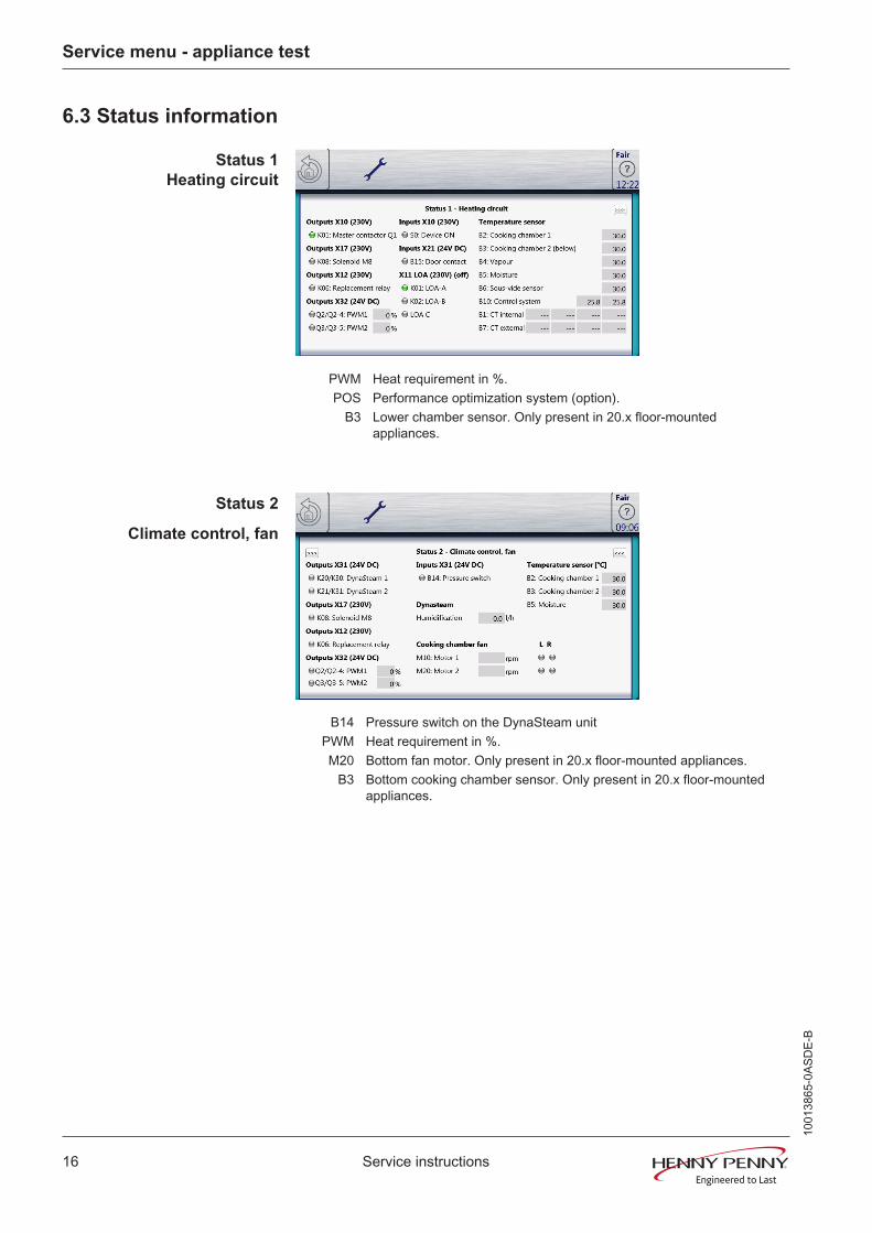
6.3 Status information
Status 1Heating circuit
PWM Heat requirement in %.POS Performance optimization system (option).
B3 Lower chamber sensor. Only present in 20.x floor-mountedappliances.
Status 2
Climate control, fan
B14 Pressure switch on the DynaSteam unitPWM Heat requirement in %.M20 Bottom fan motor. Only present in 20.x floor-mounted appliances.
B3 Bottom cooking chamber sensor. Only present in 20.x floor-mountedappliances.
1001
3865
-0AS
DE-
B

Service menu - appliance test
17Service instructions
Status 3
WaveClean
K04 Magnetic valve for water vapor elimination & siphon fillingB15 Reed contact switchB14 Pressure switch on the DynaSteam unit
B3 Bottom cooking chamber sensor. Only present in 20.x pedestal unit
Status 4
Miscellaneous
K10 Activation for optional condensation hoodB15 Reed contact switch
K03, K07 Not in useK13, K14 Not in use
B3 Bottom cooking chamber sensor. Only present in 20.x pedestal unit
1001
3865
-0AS
DE-
B
Service menu - appliance test
18 Service instructions
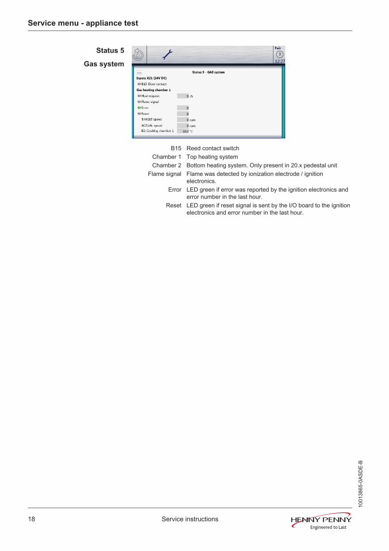
Status 5
Gas system
B15 Reed contact switchChamber 1 Top heating systemChamber 2 Bottom heating system. Only present in 20.x pedestal unit
Flame signal Flame was detected by ionization electrode / ignitionelectronics.
Error LED green if error was reported by the ignition electronics anderror number in the last hour.
Reset LED green if reset signal is sent by the I/O board to the ignitionelectronics and error number in the last hour.
1001
3865
-0AS
DE-
B

Service menu - appliance test
19Service instructions
6.4 CombiDoctor
Description The CombiDoctor offers an automatic check of the climate controland the WaveClean automatic cleaning. The tests are possibleindividually or as overall test. For instructions on performing, see thetouchscreen.
Overview
Selecting a program Select a program by adjusting the roller.
Program description 1 Climate
Automatic checking of the following areas/components
• Heating circuit
– Heating body, failure of a phase (only for energy type electric)
– Semiconductor relay SSR (only for energy type electric)
– Gas system (only for energy type gas)
– Temperature control
– DynaSteam steaming unit
– Air inlet flap
2 WaveClean
• Automatic checking of the WaveClean cleaning
– WaveClean pump (circulation pump)
– Siphon pump (drainage pump)
– Magnetic valve for water vapor elimination & siphon filling
– Reed contact switch of the cooking chamber doorStarting the program Touch the "START" field.
Evaluation The test result appears on the touchscreen.Entry in HACCP memory.
1001
3865
-0AS
DE-
B
Service menu - appliance test
20 Service instructions
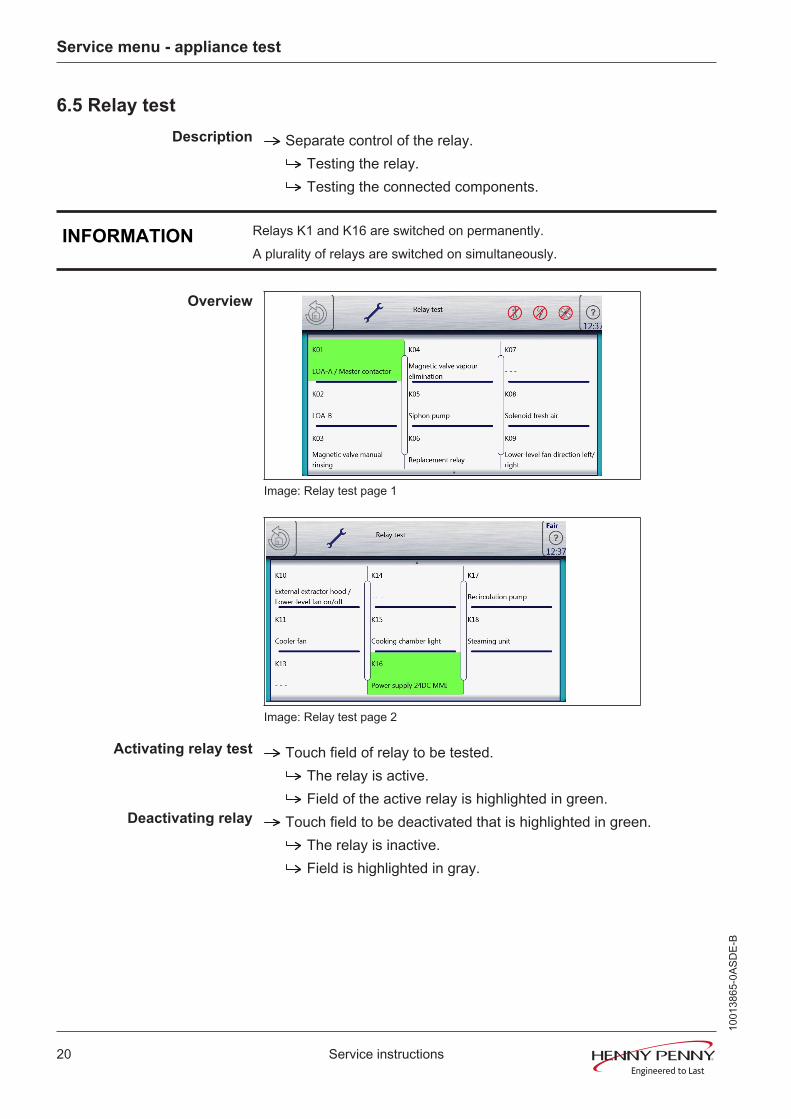
6.5 Relay test
Description Separate control of the relay.Testing the relay.Testing the connected components.
INFORMATION Relays K1 and K16 are switched on permanently.A plurality of relays are switched on simultaneously.
Overview
Image: Relay test page 1
Image: Relay test page 2
Activating relay test Touch field of relay to be tested.The relay is active.Field of the active relay is highlighted in green.
Deactivating relay Touch field to be deactivated that is highlighted in green.The relay is inactive.Field is highlighted in gray.
1001
3865
-0AS
DE-
B

Service menu - appliance test
21Service instructions
Relay overview Relay Connector
No. Description Information
K1 X10 2 Main contactor Q1 230V AC
K1 X11 1 POS A 230V AC
K2 X11 2 POS B 230V AC
K3 Solenoid valve for manual rinse 230V AC
K4 X12 3 Solenoid valve for vaporquenching K12
230V AC
K5 X12 4 Siphon pump G24 230V AC
K6 X12 5 Backup relay K6 230V AC
K7 Not in use
K8 X17 1 Lift magnet fresh air M8 230V AC
K9 Junior fan left / right direction
K10 X13 1/2 Control for condensation hood Potentialfree
K10 Junior fan on/off
K11 X14 2 Cooling fan G7 230V AC
K13 Not in use
K14 Not in use
K15 X1 2 Cooking chamber light 230V AC
K16 X9 1/2 Supply for control panel (MMI) 24V DC
K17 X12 1 Circulating pump G16 230V AC
K18 X31 1 -4 Steaming unit (switched directly,not via relay)
24V DC
1001
3865
-0AS
DE-
B

Service menu - appliance test
22 Service instructions
6.6 WaveClean Test
Overview
Description WaveClean test program for function check.Circulation pumpSiphon pumpMagnetic valve for water fillingDoor seal / leak tightness in door area
INFORMATION Follow the instructions on the touch screen.The test is used exclusively for functional testing and not to clean the cookingchamber.
Starting the test Touch the "START" field.Checking of the cooking chamber temperature.Automatic cooling off of the cooking chamber if > 70°C.
Rinse and fill up siphon.Draining by pump G24.Filling by magnetic valve K12.
Circulation and heating.The circulation pump G16 is switched on.Heating of the cooking chamber to 55°C.
Rinse DynaSteam and siphonDynaSteam steaming unit is switched on.Another water change from the siphon.
After 30 minutes, the WaveCleanTest ends.
Canceling the test An abortion is possible at any time.Touch the "STOPP" field.
Automatic rinsing of the siphon and test cancellation.
1001
3865
-0AS
DE-
B
Service menu - appliance test
23Service instructions
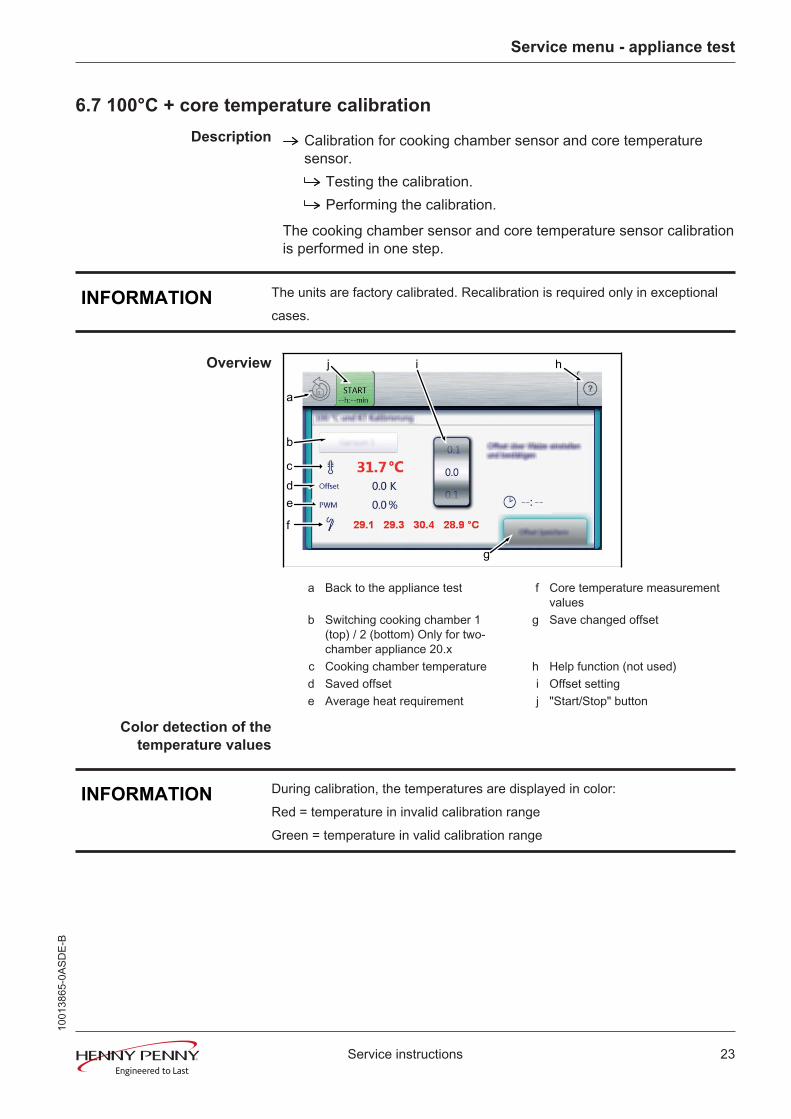
6.7 100°C + core temperature calibration
Description Calibration for cooking chamber sensor and core temperaturesensor.
Testing the calibration.Performing the calibration.
The cooking chamber sensor and core temperature sensor calibrationis performed in one step.
INFORMATION The units are factory calibrated. Recalibration is required only in exceptionalcases.
Overview
b
a
g
hij
cde
f
a Back to the appliance test f Core temperature measurementvalues
b Switching cooking chamber 1(top) / 2 (bottom) Only for two-chamber appliance 20.x
g Save changed offset
c Cooking chamber temperature h Help function (not used)d Saved offset i Offset settinge Average heat requirement j "Start/Stop" button
Color detection of thetemperature values
INFORMATION During calibration, the temperatures are displayed in color:Red = temperature in invalid calibration rangeGreen = temperature in valid calibration range
1001
3865
-0AS
DE-
B
Service menu - appliance test
24 Service instructions
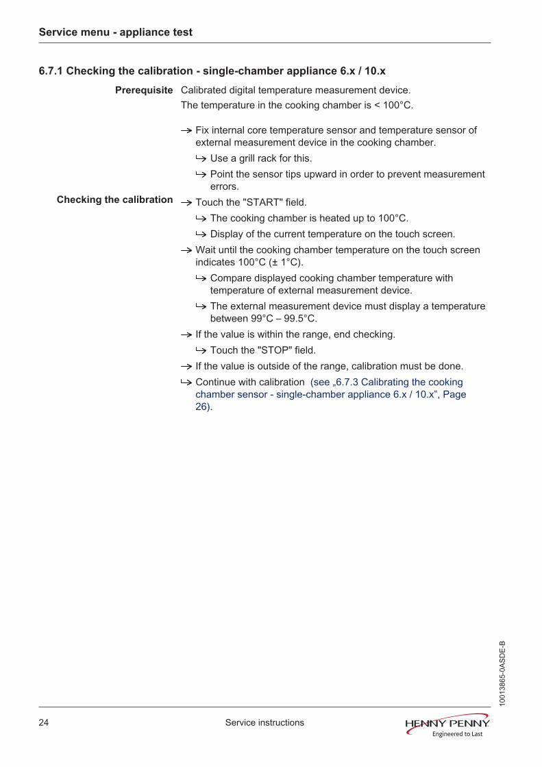
6.7.1 Checking the calibration - single-chamber appliance 6.x / 10.x
Prerequisite Calibrated digital temperature measurement device.The temperature in the cooking chamber is < 100°C.
Fix internal core temperature sensor and temperature sensor ofexternal measurement device in the cooking chamber.
Use a grill rack for this.Point the sensor tips upward in order to prevent measurementerrors.
Checking the calibration Touch the "START" field.The cooking chamber is heated up to 100°C.Display of the current temperature on the touch screen.
Wait until the cooking chamber temperature on the touch screenindicates 100°C (± 1°C).
Compare displayed cooking chamber temperature withtemperature of external measurement device.The external measurement device must display a temperaturebetween 99°C – 99.5°C.
If the value is within the range, end checking.Touch the "STOP" field.
If the value is outside of the range, calibration must be done.Continue with calibration (see „6.7.3 Calibrating the cookingchamber sensor - single-chamber appliance 6.x / 10.x‟, Page26).
1001
3865
-0AS
DE-
B

Service menu - appliance test
25Service instructions
6.7.2 Checking the calibration - two-chamber appliance 20.x
INFORMATION Two-chamber appliances (20.x) are equipped with two cooking chamber sen-sors.
Prerequisite Two calibrated digital measurement devices or two-channelmeasurement device.The temperature in the cooking chamber is < 100°C.
Fix the temperature sensor of the two external measurementdevices in the middle of the top and bottom chambers in thecooking chamber respectively. Fix the core temperature sensor inthe middle of the bottom chamber.
Use a grill rack for this.Point the sensor tips upward in order to prevent measurementerrors.
Checking the calibration Touch the "START" field.The cooking chamber is heated up to 100°C.Display of the current temperature on the touch screen.
Wait until the cooking chamber temperature indicates 100°C (±1°C).
Compare displayed cooking chamber temperature withtemperature of external measurement device.The external measurement device for the cooking chamber 1top must display a temperature between 99°C – 99.5°C.
Touch the "Cooking chamber 1" fieldSwitch to cooking chamber 2 bottomThe field changes to "Cooking chamber 2"The external measurement device must display a temperaturebetween 99°C – 99.5°C.
If the values are within the range, end checking.Touch the "STOP" field.
If one of the values is outside of the range, calibration must bedone.
Continue with calibration (see „6.7.4 Calibrating the cookingchamber sensor - two-chamber appliance 20.x‟, Page 27).
1001
3865
-0AS
DE-
B
Service menu - appliance test
26 Service instructions
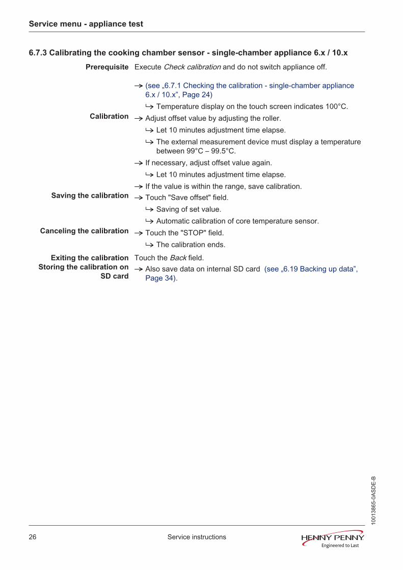
6.7.3 Calibrating the cooking chamber sensor - single-chamber appliance 6.x / 10.x
Prerequisite Execute Check calibration and do not switch appliance off.
(see „6.7.1 Checking the calibration - single-chamber appliance6.x / 10.x‟, Page 24)
Temperature display on the touch screen indicates 100°C.Calibration Adjust offset value by adjusting the roller.
Let 10 minutes adjustment time elapse.The external measurement device must display a temperaturebetween 99°C – 99.5°C.
If necessary, adjust offset value again.Let 10 minutes adjustment time elapse.
If the value is within the range, save calibration.Saving the calibration Touch "Save offset" field.
Saving of set value.Automatic calibration of core temperature sensor.
Canceling the calibration Touch the "STOP" field.The calibration ends.
Exiting the calibration Touch the Back field.Storing the calibration on
SD cardAlso save data on internal SD card (see „6.19 Backing up data‟,Page 34).
1001
3865
-0AS
DE-
B
Service menu - appliance test
27Service instructions
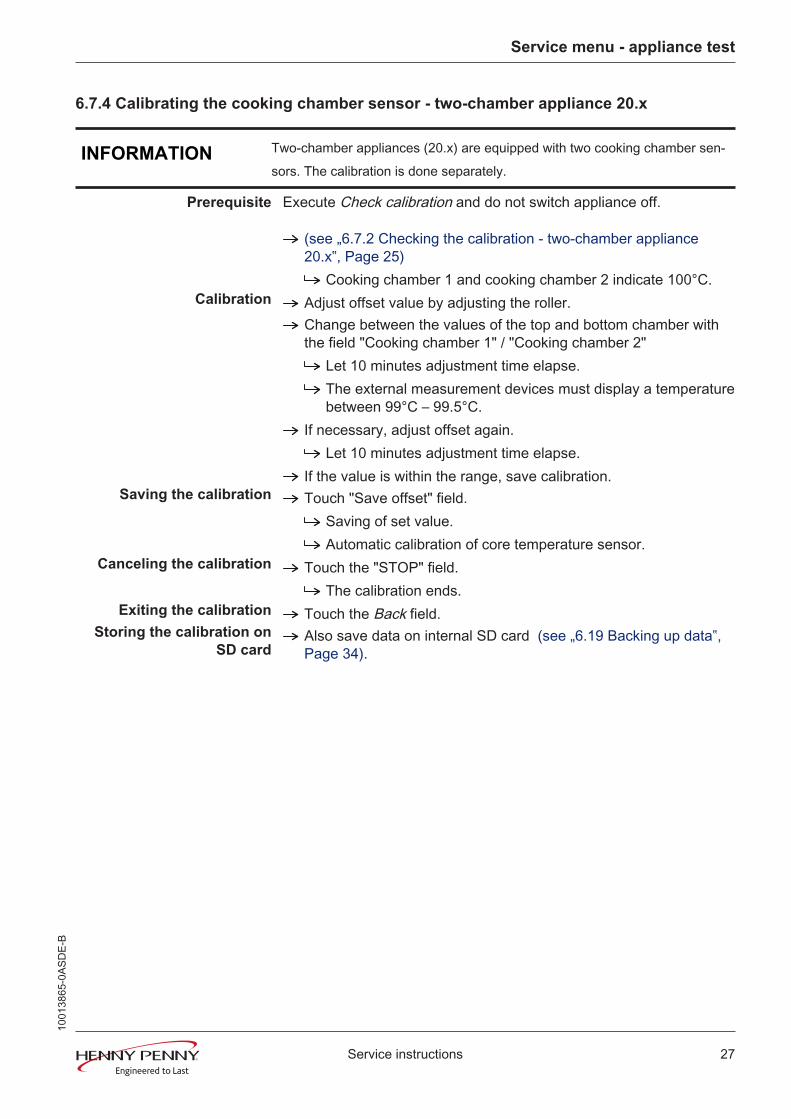
6.7.4 Calibrating the cooking chamber sensor - two-chamber appliance 20.x
INFORMATION Two-chamber appliances (20.x) are equipped with two cooking chamber sen-sors. The calibration is done separately.
Prerequisite Execute Check calibration and do not switch appliance off.
(see „6.7.2 Checking the calibration - two-chamber appliance20.x‟, Page 25)
Cooking chamber 1 and cooking chamber 2 indicate 100°C.Calibration Adjust offset value by adjusting the roller.
Change between the values of the top and bottom chamber withthe field "Cooking chamber 1" / "Cooking chamber 2"
Let 10 minutes adjustment time elapse.The external measurement devices must display a temperaturebetween 99°C – 99.5°C.
If necessary, adjust offset again.Let 10 minutes adjustment time elapse.
If the value is within the range, save calibration.Saving the calibration Touch "Save offset" field.
Saving of set value.Automatic calibration of core temperature sensor.
Canceling the calibration Touch the "STOP" field.The calibration ends.
Exiting the calibration Touch the Back field.Storing the calibration on
SD cardAlso save data on internal SD card (see „6.19 Backing up data‟,Page 34).
1001
3865
-0AS
DE-
B
Service menu - appliance test
28 Service instructions
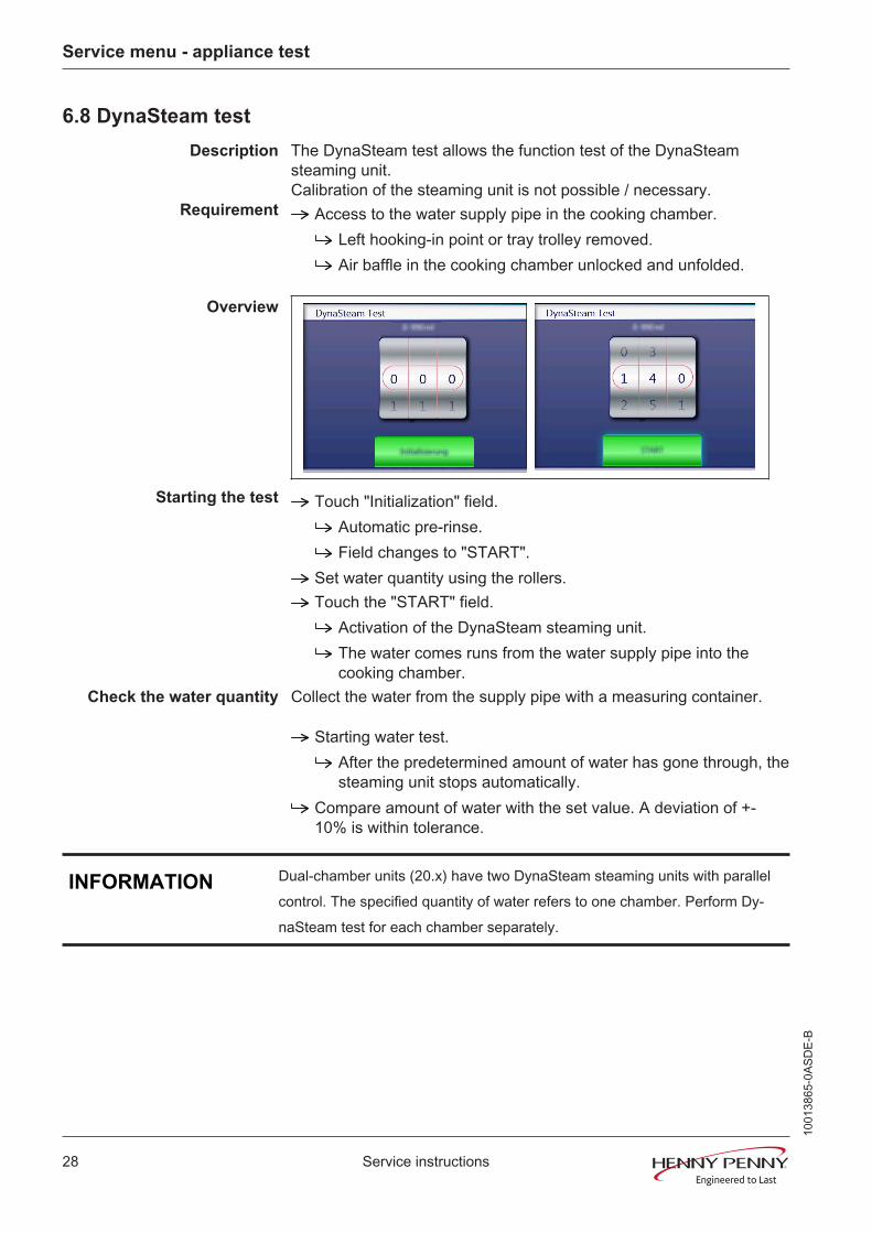
6.8 DynaSteam test
Description The DynaSteam test allows the function test of the DynaSteamsteaming unit. Calibration of the steaming unit is not possible / necessary.
Requirement Access to the water supply pipe in the cooking chamber.Left hooking-in point or tray trolley removed.Air baffle in the cooking chamber unlocked and unfolded.
Overview
Starting the test Touch "Initialization" field.Automatic pre-rinse.Field changes to "START".
Set water quantity using the rollers.Touch the "START" field.
Activation of the DynaSteam steaming unit.The water comes runs from the water supply pipe into thecooking chamber.
Check the water quantity Collect the water from the supply pipe with a measuring container.
Starting water test.After the predetermined amount of water has gone through, thesteaming unit stops automatically.
Compare amount of water with the set value. A deviation of +-10% is within tolerance.
INFORMATION Dual-chamber units (20.x) have two DynaSteam steaming units with parallelcontrol. The specified quantity of water refers to one chamber. Perform Dy-naSteam test for each chamber separately.
1001
3865
-0AS
DE-
B
Service menu - appliance test
29Service instructions
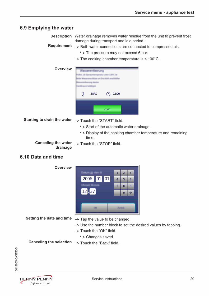
6.9 Emptying the water
Description Water drainage removes water residue from the unit to prevent frostdamage during transport and idle period.
Requirement Both water connections are connected to compressed air.The pressure may not exceed 6 bar.
The cooking chamber temperature is < 130°C.
Overview
Starting to drain the water Touch the "START" field.Start of the automatic water drainage.Display of the cooking chamber temperature and remainingtime.
Canceling the waterdrainage
Touch the "STOP" field.
6.10 Data and time
Overview
Setting the date and time Tap the value to be changed.Use the number block to set the desired values by tapping.Touch the "OK" field.
Changes saved.Canceling the selection Touch the "Back" field.
1001
3865
-0AS
DE-
B
Service menu - appliance test
30 Service instructions
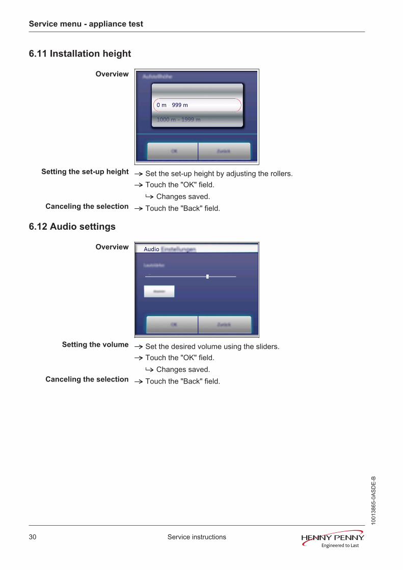
6.11 Installation height
Overview
Setting the set-up height Set the set-up height by adjusting the rollers.Touch the "OK" field.
Changes saved.Canceling the selection Touch the "Back" field.
6.12 Audio settings
Overview
Setting the volume Set the desired volume using the sliders.Touch the "OK" field.
Changes saved.Canceling the selection Touch the "Back" field.10
0138
65-0
ASD
E-B

Service menu - appliance test
31Service instructions
6.13 Select signal tones
Overview
Set signal tones Set the signal tone by adjusting the rollers.Touch the "OK" field.
Changes saved.Canceling the selection Touch the "Back" field.
6.14 LOA activation (only for energy type electric)
Description Software activation for the optional connection to a customer-suppliedperformance optimization system.
INFORMATION An additional modification of the appliance is required. With activation withoutretrofitting, the heating circuit will not be activated.
Overview
Changing the setting Touch the "OK" field.Change saved.Automatic restart of the software.
Canceling the selection Touch the "Back" field.
6.15 Exporting log data
Description Log data export to an external USB flash drive. The function is onlyrequired after consultation.
Exporting log data Perform according to instructions on the touchscreen.
1001
3865
-0AS
DE-
B

Service menu - appliance test
32 Service instructions
Touch the Confirmation field.Log data export begins.
1001
3865
-0AS
DE-
B

Service menu - appliance test
33Service instructions
6.16 Software update
Description Update of the software via the USB interface.Additional content (help texts, cookbooks, videos) will not beupdated.
Performing the update Perform according to instructions on the touchscreen anddescription (see „7.1 Software update‟, Page 41).Tap the "OK" field.
Update begins.Then a confirmation appears on the touchscreen.
6.17 Importing additional content
Description Import of additional content (videos, graphics, help texts). Import isabsolutely essential after the operating panel has been replaced.
Importing content Perform according to instructions on the touchscreen.Touch the Confirmation field.
Import the content.Then a confirmation appears on the touchscreen.
Tap the "OK" field.
1001
3865
-0AS
DE-
B

Service menu - appliance test
34 Service instructions
6.18 Restoring data
Description Import function of parameters stored on the SD card. Import isabsolutely essential after the operating panel has been replaced.
Restoring data Perform according to instructions on the touchscreen.Touch the Confirmation field.
Restoring of the data from the SD card.Tap the "OK" field.
Automatic restart of the software.
6.19 Backing up data
Description Export function of the parameters (for example, calibration values).Storage of the data on the internal SD card or USB stick (if present).
Backing up data Perform according to instructions on the touchscreen.Touch the Confirmation field.
Back-up of the data.Then a confirmation appears on the touchscreen.
Tap the "OK" field.
1001
3865
-0AS
DE-
B
Service menu - appliance test
35Service instructions
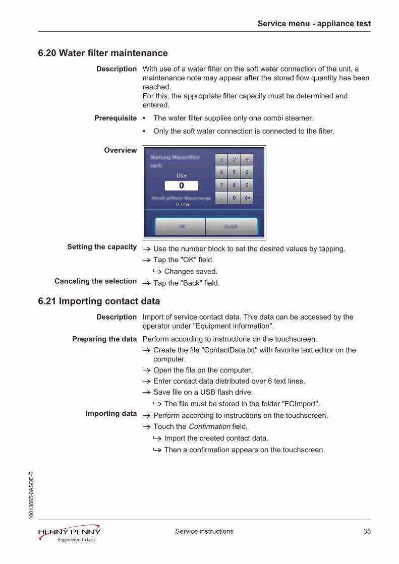
6.20 Water filter maintenance
Description With use of a water filter on the soft water connection of the unit, amaintenance note may appear after the stored flow quantity has beenreached.For this, the appropriate filter capacity must be determined andentered.
Prerequisite • The water filter supplies only one combi steamer.
• Only the soft water connection is connected to the filter.
Overview
Setting the capacity Use the number block to set the desired values by tapping.Tap the "OK" field.
Changes saved.Canceling the selection Tap the "Back" field.
6.21 Importing contact data
Description Import of service contact data. This data can be accessed by theoperator under "Equipment information".
Preparing the data Perform according to instructions on the touchscreen.Create the file "ContactData.txt" with favorite text editor on thecomputer.Open the file on the computer.Enter contact data distributed over 6 text lines.Save file on a USB flash drive.
The file must be stored in the folder "FCImport".Importing data Perform according to instructions on the touchscreen.
Touch the Confirmation field.Import the created contact data.Then a confirmation appears on the touchscreen.
1001
3865
-0AS
DE-
B

Service menu - appliance test
36 Service instructions
6.22 Setting units
Overview
To convert the units 1. Select the desired temperature and volume.2. Touch the "OK" field.
6.23 Backup relay
Description The control board has a spare relay, which allows alternative use incase of a relay failure. This is only possible with the listed relays.
Locate defective relay Call relay test in the service menu.Perform relay test. Locate defective relay by examining theoutput voltage at the corresponding outputs on the controlcircuit board.
Occupying the spare relay Do rewiring according to the table.
Example: When using it for K8 (solenoid M8), rewire line fromconnector X17.1 to X12.5.
INFORMATION In case of changes to the wiring, label or deposit note in the unit.
Overview
Assigning the backup relay Select the defective relay by means of the roller.Touch the "OK" field.
Changes saved.
Canceling the selection Touch the "Back" field.Relay overview
1001
3865
-0AS
DE-
B
Service menu - appliance test
37Service instructions
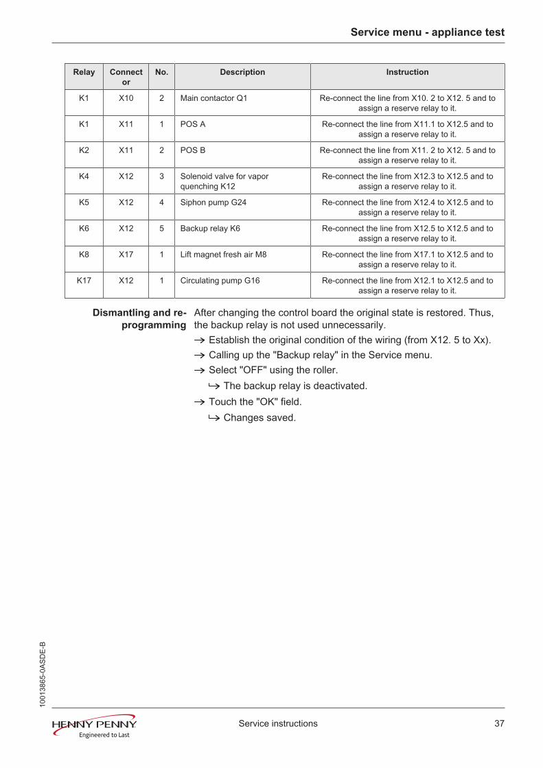
Relay Connector
No. Description Instruction
K1 X10 2 Main contactor Q1 Re-connect the line from X10. 2 to X12. 5 and toassign a reserve relay to it.
K1 X11 1 POS A Re-connect the line from X11.1 to X12.5 and toassign a reserve relay to it.
K2 X11 2 POS B Re-connect the line from X11. 2 to X12. 5 and toassign a reserve relay to it.
K4 X12 3 Solenoid valve for vaporquenching K12
Re-connect the line from X12.3 to X12.5 and toassign a reserve relay to it.
K5 X12 4 Siphon pump G24 Re-connect the line from X12.4 to X12.5 and toassign a reserve relay to it.
K6 X12 5 Backup relay K6 Re-connect the line from X12.5 to X12.5 and toassign a reserve relay to it.
K8 X17 1 Lift magnet fresh air M8 Re-connect the line from X17.1 to X12.5 and toassign a reserve relay to it.
K17 X12 1 Circulating pump G16 Re-connect the line from X12.1 to X12.5 and toassign a reserve relay to it.
Dismantling and re-programming
After changing the control board the original state is restored. Thus,the backup relay is not used unnecessarily.
Establish the original condition of the wiring (from X12. 5 to Xx).Calling up the "Backup relay" in the Service menu.Select "OFF" using the roller.
The backup relay is deactivated.Touch the "OK" field.
Changes saved.
1001
3865
-0AS
DE-
B
Service menu - appliance test
38 Service instructions
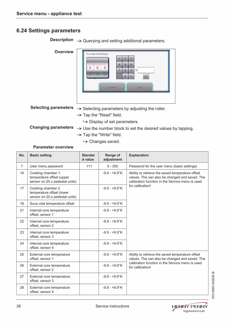
6.24 Settings parameters
Description Querying and setting additional parameters.
Overview
Selecting parameters Selecting parameters by adjusting the roller.Tap the "Read" field.
Display of set parameters.Changing parameters Use the number block to set the desired values by tapping.
Tap the "Write" field.Changes saved.
Parameter overview
No. Basic setting Standard value
Range ofadjustment
Explanation
7 User menu password 111 0 - 300 Password for the user menu (basic settings)
16 Cooking chamber 1temperature offset (uppersensor on 20.x pedestal units)
-9.9 - +9.9°K Ability to retrieve the saved temperature offsetvalues. The can also be changed and saved. Thecalibration function in the Service menu is usedfor calibration!
17 Cooking chamber 2temperature offset (lowersensor on 20.x pedestal units)
-9.9 - +9.9°K
18 Sous vide temperature offset -9.9 - +9.9°K
21 Internal core temperatureoffset, sensor 1
-9.9 - +9.9°K
22 Internal core temperatureoffset, sensor 2
-9.9 - +9.9°K
23 Internal core temperatureoffset, sensor 3
-9.9 - +9.9°K
24 Internal core temperatureoffset, sensor 4
-9.9 - +9.9°K
25 External core temperatureoffset, sensor 1
-9.9 - +9.9°K Ability to retrieve the saved temperature offsetvalues. The can also be changed and saved. Thecalibration function in the Service menu is usedfor calibration!26 External core temperature
offset, sensor 2-9.9 - +9.9°K
27 External core temperatureoffset, sensor 3
-9.9 - +9.9°K
28 External core temperatureoffset, sensor 4
-9.9 - +9.9°K
1001
3865
-0AS
DE-
B
Service menu - appliance test
39Service instructions
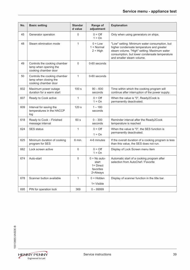
No. Basic setting Standard value
Range ofadjustment
Explanation
45 Generator operation 0 0 = Off1 = On
Only when using generators on ships.
48 Steam elimination mode 1 0 = Low1 = Normal
2 = High
"Low" setting: Minimum water consumption, buthigher condensate temperature and greatersteam volume. "High" setting: Maximum waterconsumption, but lower condensate temperatureand smaller steam volume.
49 Controls the cooking chamberlamp when opening thecooking chamber door
0 0-60 seconds
50 Controls the cooking chamberlamp when closing thecooking chamber door
1 0-60 seconds
602 Maximum power outageduration for a warm start
100 s 90 – 600seconds
Time within which the cooking program willcontinue after interruption of the power supply.
607 Ready to Cook active 1 0 = Off1 = On
When the value is "0", Ready2Cook ispermanently deactivated.
609 Interval for saving thetemperatures in the HACCPlog
120 s 1 – 180seconds
618 Ready to Cook – Finishedmessage interval
60 s 0 – 300seconds
Reminder interval after the Ready2Cooktemperature is reached
624 SES status 1 0 = Off
1 = On
When the value is "0", the SES function ispermanently deactivated.
625 Minimum duration of cookingprogram for SES
6 min. 4-6 minutes If the overall duration of a cooking program is lessthan this value, the SES does not run.
662 Lock screen active 0 0 = Off1 = On
Display of Lock Screen menu item
674 Auto-start 0 0 = No auto-start
1= Directfavorites2=Always
Automatic start of a cooking program afterselection from AutoChef / Favorite
678 Scanner button available 1 0 = Hidden
1= Visible
Display of scanner function in the title bar.
695 PIN for operation lock 369 0 – 99999
1001
3865
-0AS
DE-
B
Service menu - appliance test
40 Service instructions
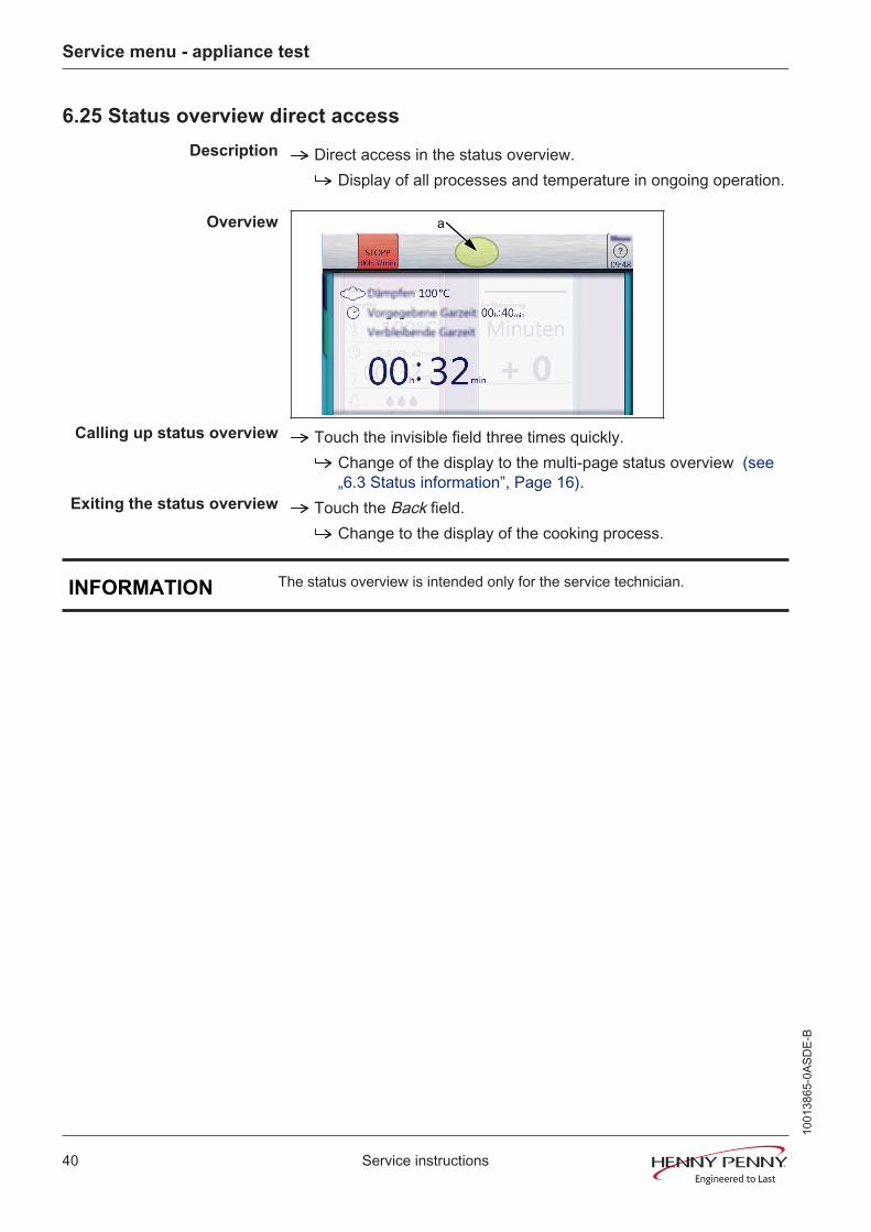
6.25 Status overview direct access
Description Direct access in the status overview.Display of all processes and temperature in ongoing operation.
Overview a
Calling up status overview Touch the invisible field three times quickly.Change of the display to the multi-page status overview (see„6.3 Status information‟, Page 16).
Exiting the status overview Touch the Back field.Change to the display of the cooking process.
INFORMATION The status overview is intended only for the service technician.
1001
3865
-0AS
DE-
B

Software
41Service instructions
7 Software
7.1 Software update
Prerequisite USB stick.Maximum size 32 GB.Formatting FAT32 (standard) or FAT.The disk should be empty if possible.
Current software update.The update is provided as packed ZIP file.
Preparing the USB stick Open and download .zip file and unzip. In general, the unzippedfolder is in the same directory as the previously compressed one.Copy unzipped folder "MMIUpdate" to the USB stick.
The update file is in the folder.The file has the extension ".ugl".For example, "012200.ugl" (software update V1.22).
Inserting the USB stick
The USB interface is behind the cover on the bottom left of thehousing.
1001
3865
-0AS
DE-
B

Software
42 Service instructions
Performing the update Switch the unit on.Tap the "Unit functions" field.
Display of Unit functions menu.
Tap "Settings" field.Display of window "PIN".
Enter password and tap Confirm field.The password for the Settings menu is 111.
Select the "Software update" field on the left area of the menu byswiping.Tap the "Software update" field.Tap the "OK" field.
The update begins.
INFORMATION The update can take up to 20 minutes. The software is restarted several times.Do not switch unit off.
Then a confirmation appears on the touchscreen.Tap the "OK" field.
The software restarts automatically.
1001
3865
-0AS
DE-
B

Software
43Service instructions
7.2 Importing additional content
Description Import function for manufacturer contents:
• Cookbook graphics
• Help information
• Sound filesPrerequisite USB stick.
Maximum size 32 GB.Formatting FAT32 (standard) or FAT.The disk should be empty if possible.
Current additional content.Additional contents are provided as packed .ZIP file.
Preparing the USB stick Open and download .zip file and unzip. In general, the unzippedfolder is in the same directory as the previously compressed one.Copy the unzipped folder "MMIContent" to the USB stick.
In the folder there are other subfolders. This may not bechanged.
Inserting the USB stick
The USB interface is behind the cover on the bottom left of thehousing.
1001
3865
-0AS
DE-
B
Software
44 Service instructions
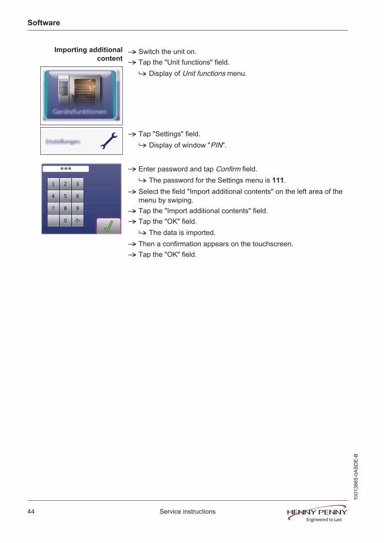
Importing additionalcontent
Switch the unit on.Tap the "Unit functions" field.
Display of Unit functions menu.
Tap "Settings" field.Display of window "PIN".
Enter password and tap Confirm field.The password for the Settings menu is 111.
Select the field "Import additional contents" on the left area of themenu by swiping.Tap the "Import additional contents" field.Tap the "OK" field.
The data is imported.Then a confirmation appears on the touchscreen.Tap the "OK" field.
1001
3865
-0AS
DE-
B
Software
45Service instructions
7.3 Importing the manufacturer's cookbook
Prerequisite USB stick.On the unit, the software version 1.29 (from 04/2014) or higher isinstalled.
Checking the software version in the unit's information (see„6.2 Appliance information‟, Page 15).If necessary, perform software update (see „7.1 Softwareupdate‟, Page 41).
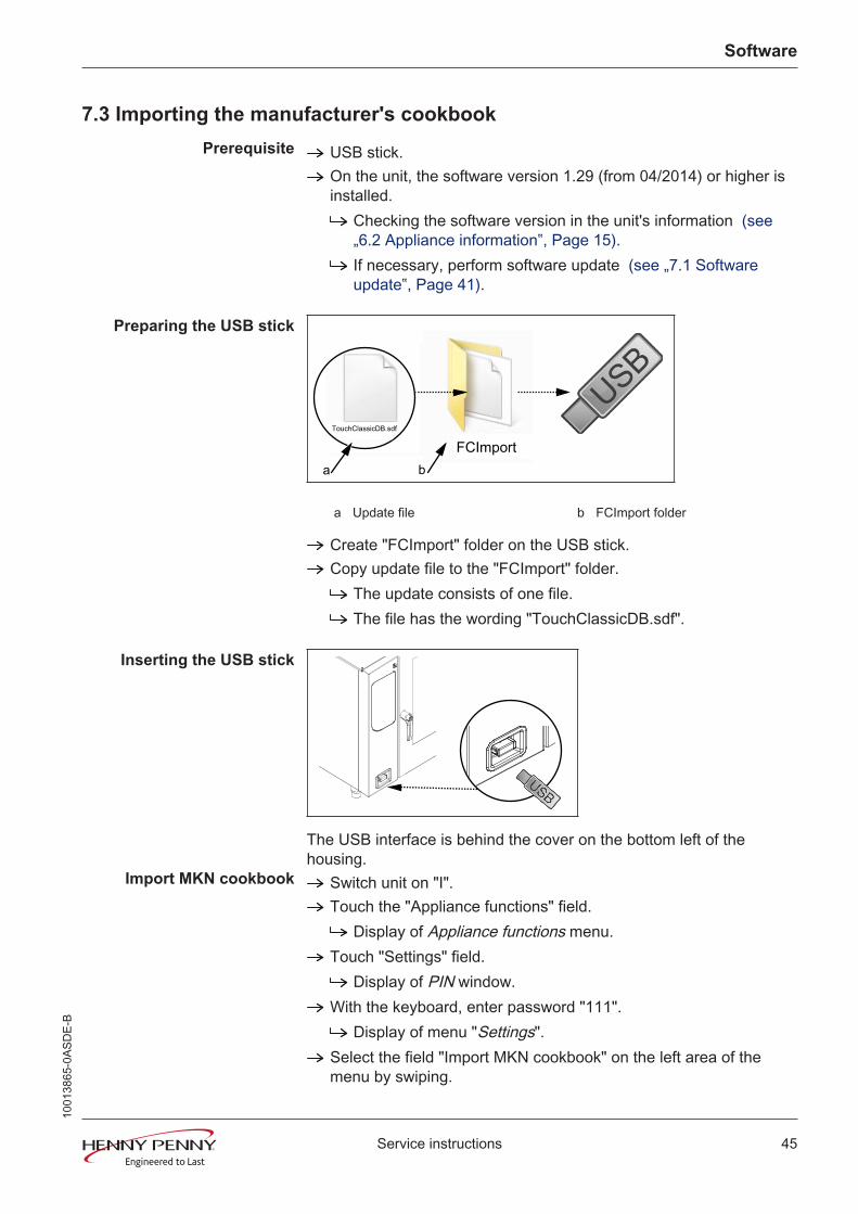
Preparing the USB stick
a bFCImport
TouchClassicDB.sdf
a Update file b FCImport folder
Create "FCImport" folder on the USB stick.Copy update file to the "FCImport" folder.
The update consists of one file.The file has the wording "TouchClassicDB.sdf".
Inserting the USB stick
The USB interface is behind the cover on the bottom left of thehousing.
Import MKN cookbook Switch unit on "I".Touch the "Appliance functions" field.
Display of Appliance functions menu.Touch "Settings" field.
Display of PIN window.With the keyboard, enter password "111".
Display of menu "Settings".Select the field "Import MKN cookbook" on the left area of themenu by swiping.
1001
3865
-0AS
DE-
B
Software
46 Service instructions
Tap "Import MKN cookbook".Touch the Confirmation field.
Import begins.Then a confirmation appears on the touchscreen.
Exit selection Touch the Back field.
1001
3865
-0AS
DE-
B
Trade show mode
47Service instructions
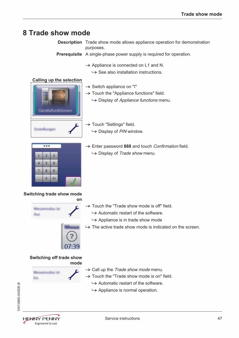
8 Trade show modeDescription Trade show mode allows appliance operation for demonstration
purposes.Prerequisite A single-phase power supply is required for operation.
Appliance is connected on L1 and N.See also installation instructions.
Calling up the selection
Switch appliance on "I"Touch the "Appliance functions" field.
Display of Appliance functions menu.
Touch "Settings" field.Display of PIN window.
Enter password 888 and touch Confirmation field.Display of Trade show menu.
Switching trade show modeon
Touch the "Trade show mode is off" field.Automatic restart of the software.Appliance is in trade show mode
The active trade show mode is indicated on the screen.
Switching off trade showmode
Call up the Trade show mode menu.Touch the "Trade show mode is on" field.
Automatic restart of the software.Appliance is normal operation.
1001
3865
-0AS
DE-
B
Electronics
48 Service instructions
9 Electronics
9.1 Overview of the controller
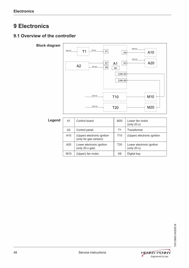
Block diagram
X8
T10
T20
M10
M20
X3
X4 A10
A20A1A2
T1230V AC 18V AC
230V AC
230V AC
CAN X6
CAN X5
24V DC
X7
X9
X1
230V AC
230V AC
Legend A1 Control board M20 Lower fan motor(only 20.x)
A2 Control panel T1 Transformer
A10 (Upper) electronic ignition(only for gas version)
T10 (Upper) electronic ignition
A20 Lower electronic ignition(only 20.x gas)
T20 Lower electronic ignition(only 20.x)
M10 (Upper) fan motor X8 Digital key
1001
3865
-0AS
DE-
B

Electronics
49Service instructions
9.2 Layout of the control board
1001
3865
-0AS
DE-
B

Electronics
50 Service instructions
9.3 Configuration of the control board
Connector X1 No. Description Conductornumber
1 Input 10.7 V AC for lighting
2
3/4 Power supply I/O board 18V AC
Connector X2 Not in use
Connector X3 Digital ignition control for lower chamber (only for 20.x gasappliances)
Connector X4 Digital ignition control (only for gas appliances), for 20.x upperchamber
Connector X5 CAN bus line to the motor M1 (for 20.x upper chamber)
Connector X6 CAN bus line to the motor M2 (only for 20.x, lower chamber)
Connector X7 MMI communication
Connector X8 Digital key. Contains device-specific information.Connector X9 (24V DC) No. Description Conductor
number
1/2 Supply for control panel (MMI)
Connector X10 (230V AC) No. Description Conductornumber
1 Supply voltage for relay
2 Output K1, main contactor Q1
3 -
4/5 N
Connector X11 (230V AC)optional
No. Description Conductornumber
1 Output K1, LOA A
2 Output K2, LOA B
3 Input 230V, LOA C
4 -
5 N
Connector X12 (230V AC) No. Description Conductornumber
1 Output K17, WaveClean pump G16
2 -
3 Output K4, solenoid valve K12
4 Output K5, siphon pump G24
5 Output K6, backup relay
1001
3865
-0AS
DE-
B

Electronics
51Service instructions
No. Description Conductornumber
6 -
7 N
Connector X13 (potential-free) optional
Control for condensation hood via K10
Connector X14 (potential-free)
No. Description Conductornumber
1 Input K11, cooling fan G7 (230V AC)
2 Output K11, cooling fan G7 (230V AC)
Connector X15 / X16 Not in useConnector X17 (230V AC) No. Description Conductor
number
1 Output K8, solenoid M8
2 N for solenoid M8
Connector X19 / X20 Not in use
Connector X21 Reed contact switch for cooking chamber door B15
Connector X22 / X23 Not in use
Connector X24 B1 core temperature sensor 1
Connector X25 B2 cooking chamber sensor 1 (for 20.x upper chamber)
Connector X26 B3 cooking chamber sensor 2 (for 20.x lower chamber)
Connector X27 B4 Vapor sensor
Connector X28 B5 moisture sensor
Connector X29 (optional) B6 Sous Vide sensor, B7 core temperature sensor 2Connector X31 (24V DC) No. Description Conductor
number
1 Output +, steaming unit valve 1
2 Output -, steaming unit valve 1
3 Output +, steaming unit valve 2
4 Output -, steaming unit valve 2
5 Output +, pressure switch B14
6 Input +, from pressure switch B14
7 0 V
Connector X32 (24V DC) No. Description Conductornumber
1/2 Output SSR 1
3/4 Output SSR 2
Connector X35 Not in use
1001
3865
-0AS
DE-
B
Electronics
52 Service instructions
Button The buttons have no function and are intended for internal use.
1001
3865
-0AS
DE-
B

Electronics
53Service instructions
9.4 Safety overview
Layout
3,15A
T1-F2
3,15A
T1-F1
T1
18V AC
10,7V AC
3,15A
A1-F3
230V AC B11/B12
K12
G16
G24
K6
M8
A2
Q1
3,15A
A1-F5
230V AC
24V DC
A1
A1
E
T10 M10
T20 M20
6,3A
F4
230V AC
6,3A
F2
6,3A
F1
3,15A
A1-F2
G10
A20
A10
G20
B13 G7
Legend A1 Control board G16 WaveClean pump
A2 Control panel G24 Siphon pump
A10 Upper electronic ignition K6 Backup relay
A20 Lower electronic ignition(only 20.x)*
K12 Quenching solenoid valve
B11 (Upper) cookingchamber STB 1
M8 Solenoid
B12 Lower cooking chamberSTB 2 (only 20.x)
M10 (Upper) fan motor
B13 Thermal switch M20 Lower fan motor (only 20.x)
E Cooking chamber light Q1 Main contactor
F Fuse T1 Transformer
G7 Cooling fan T10 (Upper) electronic ignition
G10 (Upper) gas fan* T20 Lower electronic ignition (only20.x)
G20 Lower gas fan*
*= Only for gas version
1001
3865
-0AS
DE-
B
Gas technology
54 Service instructions
10 Gas technology
10.1 Basic principles
Functional diagramIonization
(Flame detection)
Glow electrode
Transformer
PWM
sig
nal
Gas
fan
spee
d
Digital electronic ignition
BUS communication
Control board A1
Gas - solenoid valve
Air
Gas heat exchanger
Fan
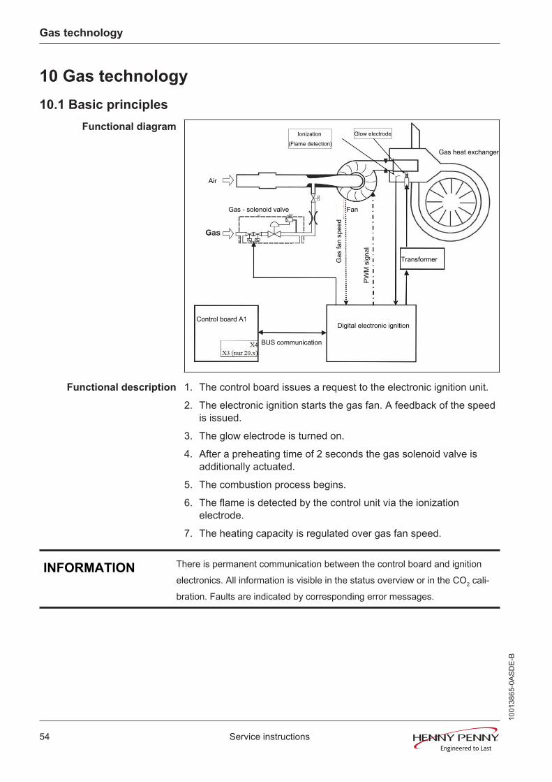
Functional description 1. The control board issues a request to the electronic ignition unit.
2. The electronic ignition starts the gas fan. A feedback of the speedis issued.
3. The glow electrode is turned on.
4. After a preheating time of 2 seconds the gas solenoid valve isadditionally actuated.
5. The combustion process begins.
6. The flame is detected by the control unit via the ionizationelectrode.
7. The heating capacity is regulated over gas fan speed.
INFORMATION There is permanent communication between the control board and ignitionelectronics. All information is visible in the status overview or in the CO2 cali-bration. Faults are indicated by corresponding error messages.
1001
3865
-0AS
DE-
B

Error messages
55Service instructions
11 Error messages
11.1 Emergency operation
Description In order to allows limited use in case of error, the appliance hasvarious emergency programs. Emergency operation is activatedautomatically and displayed. After elimination of the error indicated,the controller switches back into regular operation automatically. Areset is not necessary.
INFORMATION Emergency programs handle the limited further operation of the appliance untilservicing. Deviating cooking results and temperature deviations are possible.
Overview
6.x, 10.x tabletop units
Fault message displayed Description
Chamber sensor faulty. The core temperature sensor takes over thefunction of the cooking chamber sensor.
Water vapor sensor defective The software controls the water vaporelimination. This results in higher waterconsumption.
Internal core temperature sensor faulty. Cooking program willbe abandoned. Cooking program can be restarted afterchanging to external core temperature sensor.
The core temperature sensor is deactivated.
External core temperature sensor faulty. Cooking program willbe abandoned. Cooking program can be restarted afterchanging to internal core temperature sensor.
20.x pedestal units
Fault message displayed Description
Upper chamber sensor faulty. Measurement of the cooking chambertemperature is done exclusively by thebottom cooking chamber sensor.
Lower chamber sensor faulty. Measurement of the cooking chambertemperature is done exclusively by the topcooking chamber sensor.
Water vapor sensor defective The software controls the water vaporelimination. This results in higher waterconsumption.
Internal core temperature sensor faulty. Cooking program willbe abandoned. Cooking program can be restarted afterchanging to external core temperature sensor.
The core temperature sensor is deactivated.
External core temperature sensor faulty. Cooking program willbe abandoned. Cooking program can be restarted afterchanging to internal core temperature sensor.
Top fan defective. Only up to version 1.55. Deactivation of the top heating circuit.
Bottom fan defective. Only up to version 1.55. Deactivation of the bottom heating circuit.
1001
3865
-0AS
DE-
B

Error messages
56 Service instructions
11.2 Cooking chamber sensor defective (694, 695)
Description Emergency operation is activated automatically and displayed. Thecore temperature sensor takes over the function of the cookingchamber sensor. Cooking program with core temperature sensor isno longer available.
Location The cooking chamber sensor is in the top right of the cookingchamber.
Naming on the circuitdiagram
B2
Troubleshooting Unlock and open control panel.
Check contacting on control board A1, X25.Remove existing cooking chamber sensor from the control boardA1, X25 and plug in new cooking chamber sensor.
The fault message disappears. Replace cooking chambersensor.The fault message is still displayed. Replace control board.
Function check The measurement values can be called up in the status overview.
1001
3865
-0AS
DE-
B
Error messages
57Service instructions
11.3 Top cooking chamber sensor defective (696, 728)
Description Emergency operation is activated automatically and displayed.Measurement of the cooking chamber temperature is doneexclusively by the bottom cooking chamber sensor.
Location The cooking chamber sensor is in the top right of the cookingchamber.
Naming on the circuitdiagram
B2
Troubleshooting Unlock and open control panel.
Check contacting on control board A1, X25.Remove existing cooking chamber sensor from the control boardA1, X25 and plug in new cooking chamber sensor.
The fault message disappears. Replace cooking chambersensor.The fault message is still displayed. Replace control board.
Function check The measurement values can be called up in the status overview.
1001
3865
-0AS
DE-
B

Error messages
58 Service instructions
11.4 Bottom cooking chamber sensor defective (697, 729)
Description Emergency operation is activated automatically and displayed.Measurement of the cooking chamber temperature is doneexclusively by the top cooking chamber sensor.
Location The cooking chamber sensor is in the middle right of the cookingchamber.
Naming on the circuitdiagram
B3
Troubleshooting Unlock and open control panel.
Check contacting on control board A1, X26.Remove existing cooking chamber sensor from the control boardA1, X26 and plug in new cooking chamber sensor.
The fault message disappears. Replace cooking chambersensor.The fault message is still displayed. Replace control board.
Function check The measurement values can be called up in the status overview.
1001
3865
-0AS
DE-
B

Error messages
59Service instructions
11.5 Core temperature sensor defective (699, 700)
Description The core temperature sensor in the cooking chamber is deactivated.
Location The core temperature sensor is in the front area of the cookingchamber.
Naming on the circuitdiagram
B1
Troubleshooting Unlock and open control panel.
Check contacting on control board A1, X24.Remove existing core temperature sensor from the control boardA1 X24 and plug in new core temperature sensor.
The fault message disappears. Replace core temperaturesensor.The fault message is still displayed. Replace control board.
Function check The measurement values can be called up in the status overview.
1001
3865
-0AS
DE-
B
Error messages
60 Service instructions
11.6 Internal core temperature sensor defective (714, 716)
Description The internal core temperature sensor in the cooking chamber isdeactivated.
Location The core temperature sensor is in the front area of the cookingchamber.
Naming on the circuitdiagram
B1
Troubleshooting Identical to "Core temperature sensor defective" (see „11.5 Coretemperature sensor defective (699, 700)‟, Page 59).
11.7 External core temperature sensor defective (715, 717)
Description The external core temperature sensor is deactivated.
Location The core temperature sensor is plugged into socket X29 on thecontrol panel.
Naming on the circuitdiagram
B7
Troubleshooting Make sure that the external core temperature sensor was connectedproperly.
Replace external core temperature sensor.Check connection socket X23 for corrosion. Replace if necessary.Check contacting on control board A1, X29.Replace the control board.
Function check The measurement values can be called up in the status overview.
1001
3865
-0AS
DE-
B

Error messages
61Service instructions
11.8 Water vapor sensor defective (710)
Description Emergency operation is activated automatically and displayed. Thesoftware controls the water vapor elimination.
Location The water vapor sensor is on the left side of the siphon.
Naming on the circuitdiagram
B4
Troubleshooting Unlock and open control panel.
Check contacting on control board A1, X27.Remove existing water vapor sensor from the control board A1X27 and plug in new cooking chamber sensor.
The fault message disappears. Replace water vapor sensor.To do this, remove the left side wall.The fault message is still displayed. Replace control board.
Function check The measurement values can be called up in the status overview.
1001
3865
-0AS
DE-
B

Error messages
62 Service instructions
11.9 Excess temperature in the cooking chamber (ID73)
Description The measured temperature in the cooking chamber is outside theallowable range (electric power supply > 310°C; energy type gas >290°C). The unit is no longer operational until the cooking chambercools down. The measurement is taken by the cooking chambersensor, core temperature sensor and the moisture sensor.
Prerequisite • No display of fault messages from the temperature sensor.Troubleshooting
Type of energy - electricRemove the left side wall.Switch unit to "I"
Measure the voltage / current consumption on the load side of thesemi-conductor relay.
Voltage / current is present and the LED on at least one of thesemi-conductor relays if off.
Semiconductor relay is defective. Replace component and checkthat fan impeller is balanced.Measure the control voltage on the input side of the semi-conductor relay.
Voltage is present and the LED on at least one of thesemiconductor relays if on.
Control board A1 defective. Replace component.Troubleshooting
Type of energy - GasCO2 perform calibration.
1001
3865
-0AS
DE-
B

Error messages
63Service instructions
11.10 Overtemperature control (TMP_ID2)
Description The temperature sensor on the control board is measuring atemperature of >70°C. The unit is no longer operational until it coolsdown.
Troubleshooting Check air intake area of fan.Clean dirty air intake area.
Check that cooling fan is functioning properly. To do so, use therelay test in the Service menu to switch on the cooling fan.
The cooling fan does not start. Measure the voltage at the fan.Voltage present = Cooling fan defective. Voltage not present =Relay on the control board defective. Replace control board.
The cooling fan starts. Check surroundings and ambienttemperature. See also installation instructions.
11.11 Critical temperature in the electronics (MMI_ID50)
Description The temperature sensor on the control board is measuring atemperature of >70°C. The unit is no longer operational until it coolsdown.
Troubleshooting Check air intake area of fan.Clean dirty air intake area.
Check that cooling fan is functioning properly. To do so, use therelay test in the Service menu to switch on the cooling fan.
The cooling fan does not start. Measure the voltage at the fan.Voltage present = Cooling fan defective. Voltage not present =Relay on the control board defective. Replace control board.
The cooling fan starts. Check surroundings and ambienttemperature. See also installation instructions.
11.12 Siphon temperature very high (SOF_ID20)
Description The temperature in the siphon is >100°C. The water vapor sensor B4is used for the measurement.
Prerequisite Water supply available on-site at both water connections.Troubleshooting Fill the siphon with 2 liters of water from inside the cooking
chamber.Check the solenoid valve for steam removal K12 by means of therelay test.Perform the WaveClean test.
11.13 Risk of frost (TMP_ID72, MMI_ID51)
Description The unit is not ready for use. The temperature sensor on the controlboard is measuring a temperature of <0°C.
Troubleshooting Increase the room temperature and switch on unit again.Change location of the unit.
1001
3865
-0AS
DE-
B

Error messages
64 Service instructions
11.14 Fan defective or temperature limiter triggered (702)
Description The control board A1 does not receive any response via the CAN buscable from fan motor M10. There is an error in the safety circuit or fanarea.
Overview
1
5
1 3
a
b
c
d
a Fan motor M10 c Power supply X1b Power board T10 for fan motor d Connection for fan motor X2
Plug assignment power board
Connector X1 (c) Connector X2 (d)
1 L1 230V 1 320V DC+
2 N 2 Ground
3 PE 3 15V DC+
4 -
5 PFC
DANGER Warning: electric shock! Danger of death!
When working on the power board, make sure that energized parts are ex-posed. Work on these components during operation and up to 3 minutes afterenabling is not allows. Even if the motor is stopped and the appliance is de-en-ergized, the connection terminals and components can conducted dangerousvoltage!
Locating errors Location of whether there is an error in the STL circuit (STL =safety temperature limiter) or in the fan area.
1001
3865
-0AS
DE-
B
Error messages
65Service instructions
Switch unit on and measure voltage at main contactor Q1,terminals A1 and A2. The main contactor must be energized.
No voltage present. There is an error in the STL circuit.Troubleshooting according to "Troubleshooting safety circuit".Voltage present. There is an fault in the fan area. Troubleshootaccording to "Troubleshooting the fan".
Troubleshooting the safetycircuit
The safety temperature limiter has tripped.Reset the safety temperature limiter. Check semiconductorrelay and replace if necessary.
The safety temperature limiter has not tripped.Check fuse F3 on control board A1. Replace if necessary.Check main contactor Q1 and control board A1.Check relay K1 on the control board. If necessary, use backuprelay or replace control board.
Troubleshooting the fanmotor
Replace communication cable between motor control and motor fortest purposes and perform test run.Switch unit on "I."
Check voltage supply at connector X1.No voltage present. Fuse F1 blown. Replace power board formotor.No voltage present. Fuse F1 is not blown. Check maincontactor Q1 and control board A1.
Check output voltage at connector X2.No voltage present. Replace power board for motor.Voltage present. Replace fan motor.
Function check The measurement values can be called up in the status overview.
1001
3865
-0AS
DE-
B

Error messages
66 Service instructions
11.15 Fan defective. Cooking program was cancelled (701)
Description The control board A1 does not receive any response via the CAN buscable from fan motor M10.
Troubleshooting (see „11.14 Fan defective or temperature limiter triggered (702)‟,Page 64)
11.16 Top fan defective. Automatic switching to emergency operation(703, 705)
Description The control board A1 does not receive any response via the CAN buscable from the top fan motor M10.
Troubleshooting (see „11.14 Fan defective or temperature limiter triggered (702)‟,Page 64)
1001
3865
-0AS
DE-
B
Error messages
67Service instructions
11.17 Bottom fan defective. Automatic switching to emergency operation(704, 706)
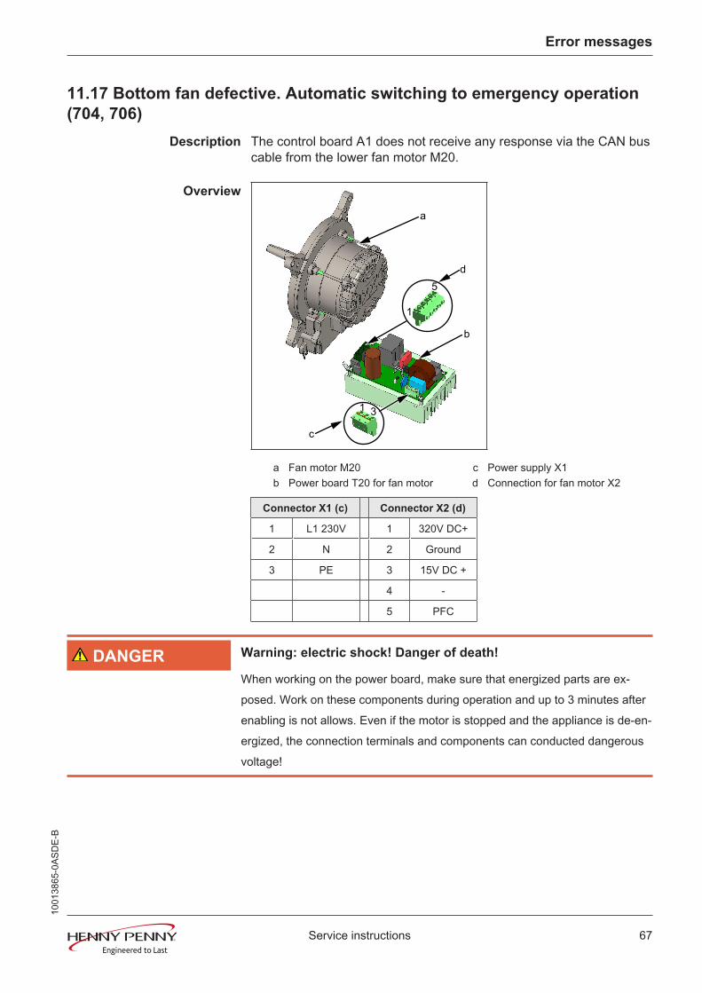
Description The control board A1 does not receive any response via the CAN buscable from the lower fan motor M20.
Overview
1
5
1 3
a
b
c
d
a Fan motor M20 c Power supply X1b Power board T20 for fan motor d Connection for fan motor X2
Connector X1 (c) Connector X2 (d)
1 L1 230V 1 320V DC+
2 N 2 Ground
3 PE 3 15V DC +
4 -
5 PFC
DANGER Warning: electric shock! Danger of death!
When working on the power board, make sure that energized parts are ex-posed. Work on these components during operation and up to 3 minutes afterenabling is not allows. Even if the motor is stopped and the appliance is de-en-ergized, the connection terminals and components can conducted dangerousvoltage!
1001
3865
-0AS
DE-
B
Error messages
68 Service instructions
Troubleshooting the safetycircuit
1. At least one of the safety temperature limiters has tripped.Reset the safety temperature limiter. Check semiconductorrelay for bottom heating circuit and replace if necessary.
2. The safety temperature limiter has not tripped.Check fuse F3 on control board A1. Replace if necessary.Check main contactor Q1 and control board A1.Check relay K1 on the control board. If necessary, use backuprelay or replace control board.
Troubleshooting the fanmotor
Replace communication cable between motor control and motor fortest purposes and perform test run.Switch unit on "I."
3. Check voltage supply at connector X1.No voltage present. Fuse F1 blown. Replace power board formotor.No voltage present. Fuse F1 is not blown. Check maincontactor Q1 and control board A1.
4. Check output voltage at connector X2.No voltage present. Replace power board for motor.Voltage present. Replace fan motor.
Function check The measurement values can be called up in the status overview.
11.18 Water pressure too low (709)
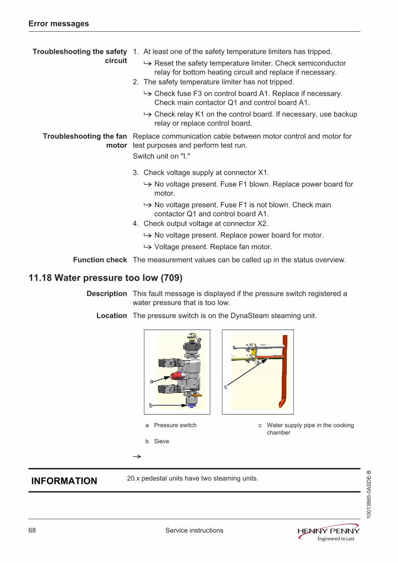
Description This fault message is displayed if the pressure switch registered awater pressure that is too low.
Location The pressure switch is on the DynaSteam steaming unit.
a
b
c
a Pressure switch c Water supply pipe in the cookingchamber
b Sieve
INFORMATION 20.x pedestal units have two steaming units.
1001
3865
-0AS
DE-
B
Error messages
69Service instructions
Naming on the circuitdiagram
B14
Troubleshooting Ensure on-site water supply to soft water connection of unit.The flow pressure at the water connection must be at least 2 bar.
Check sieve on the water connection for soiling. To do this,remove the on-site water connection to the unit.
For additional troubleshooting, swing out the air diverter in thecooking chamber.
Perform the DynaSteam test in the Service menu.Water runs through the water supply pipe into the cookingchamber.
Perform DynaSteam test again and check water quantity withmeasurement container.
The water quantity corresponds to the set quantity (±10%).Replace pressure switch.The water quantity does not correspond to the set quantity(±10%). Ensure that the supply pipe is not clogged. Replacesteaming unit.
Perform the DynaSteam test in the Service menu.No water runs through the water supply pipe into the cookingchamber.
Check water supply pipe for calcification.Ensure that the hose between the steaming unit and supply pipeis not clogged.Replace steaming unit.
1001
3865
-0AS
DE-
B
Error messages
70 Service instructions
11.19 Faulty CAN connection
Description There is a communication fault between the operating panel andcontrol panel. In addition, temperature sensor and fan fault messagesappear on the touchscreen.
Troubleshooting Replace communication cable between operating panel andcontrol panel circuit board.Replace control board.Replace operating panel.
11.20 Failure to access external EEPROM (SOF_ID)12
Description It is not possible to access the digital key (EEPROM).Troubleshooting Make sure that the digital key is oriented correctly and inserted
fully. The side with the hole must point to the sensor connections.Digital key defective.Control board defective.
11.21 Door is open - cooking program was stopped
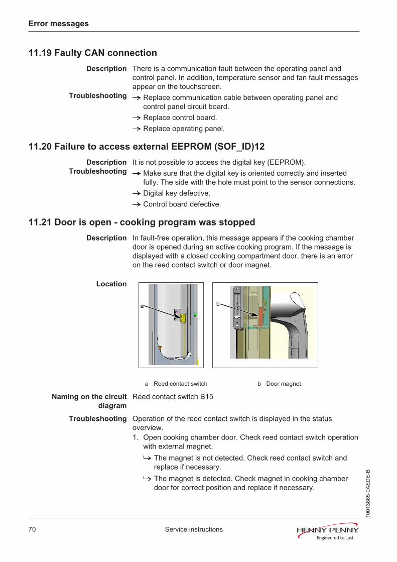
Description In fault-free operation, this message appears if the cooking chamberdoor is opened during an active cooking program. If the message isdisplayed with a closed cooking compartment door, there is an erroron the reed contact switch or door magnet.
Location
a b
a Reed contact switch b Door magnet
Naming on the circuitdiagram
Reed contact switch B15
Troubleshooting Operation of the reed contact switch is displayed in the statusoverview.1. Open cooking chamber door. Check reed contact switch operation
with external magnet.The magnet is not detected. Check reed contact switch andreplace if necessary.The magnet is detected. Check magnet in cooking chamberdoor for correct position and replace if necessary.
1001
3865
-0AS
DE-
B

Gas faults and error messages
71Service instructions
12 Gas faults and error messages
12.1 No gas (OTH_ID1)
Description This error message only appears if on the first gas request onprogram start there is no response.
Prerequisite • Ensure customer-supplied gas supply according to installationinstructions.
• The connection pressure and the flow pressure are always withinthe specifications. For this, the gas pressure must be measuredon the gas magnetic valve. Here the maximum gas requirement ofall appliances connected to the gas supply must be considered.Also make pressure measurements with maximum loading of thegas supply.
• The installed gas plate is correct.
Troubleshooting Remove the left side wall.1. Start cooking program.
Ignition is occurring.The ionization electrode or the ignition electronics does not detectthe flame.
2. Start cooking program.Ignition is not occurring. The glow electrode does not light up(visual inspection).
Check the voltage and fuses on the transformer, ignitionelectrode, and glow electrode.
3. Start cooking program.Ignition is not occurring. The glow electrode is functioningproperly.
Check gas fan for proper operation.Check the gas solenoid valve. Visually inspect and check the gasheat exchanger in the cooking chamber for leaks.
4. Start cooking program.Ignition is not occurring. The glow electrode is functioningproperly.
The ignition electronics are defective and do not activate the gasmagnetic valve.
INFORMATION Perform troubleshooting using the Service menu, CO2calibration area or thestatus overview. This is where all requirements and responses are displayed.
1001
3865
-0AS
DE-
B
Gas faults and error messages
72 Service instructions
12.2 No gas (top)(OTH_ID2)
Description This error message only appears if on the first gas request onprogram start there is no response.
The fault message refers to the upper burner on 20.x pedestal units.
Troubleshooting Further fault message as for error message No gas (see „12.1 Nogas (OTH_ID1)‟, Page 71).
12.3 No gas (bottom)(OTH_ID3)
Description This error message only appears if on the first gas request onprogram start there is no response.
The error message refers to the lower burner on 20.x pedestal units.
Troubleshooting Further fault message as for error message No gas (see „12.1 Nogas (OTH_ID1)‟, Page 71).
12.4 No flame (OTH_ID4)
Description This error message only appears if on the first gas request onprogram start the flame was detected (response from ionizationelectrode present) and then was lost (no response from the ionizationelectrode).
Troubleshooting Prerequisite and troubleshooting as for error message No gas (see„12.1 No gas (OTH_ID1)‟, Page 71).
12.5 No flame (top)(OTH_ID5)
Description This error message only appears if on the first gas request onprogram start the flame was detected (response from ionizationelectrode present) and then was lost (no response from the ionizationelectrode).
The fault message refers to the upper burner on 20.x pedestal units.
Troubleshooting Prerequisite and troubleshooting as for error message No gas (see„12.1 No gas (OTH_ID1)‟, Page 71).
12.6 No flame (bottom)(OTH_ID6)
Description This error message only appears if on the first gas request onprogram start the flame was detected (response from ionizationelectrode present) and then was lost (no response from the ionizationelectrode).
The error message refers to the lower burner on 20.x pedestal units.
Troubleshooting Prerequisite and troubleshooting as for error message No gas (see„12.1 No gas (OTH_ID1)‟, Page 71).
1001
3865
-0AS
DE-
B
Gas faults and error messages
73Service instructions
12.7 Communication fault between I/O and ignition electronics (OTH_ID25)
Description There is a communication fault between the control board and ignitionelectronics.
Troubleshooting Remove the left side wall. Unlatch and open the operating panel.Look for the following causes.
CAN bus cable between control board, connector X4 and ignitionelectronics defective.Ignition electronics defective.Control board defective.
Troubleshoot in the indicated order.
12.8 Communication fault between I/O and ignition electronics (top)(OTH_ID26)
Description There is a communication fault between the control board and ignitionelectronics for the upper burner.
Troubleshooting Remove the left side wall. Unlatch and open the operating panel.Look for the following causes.
CAN bus cable between control board, connector X4 and ignitionelectronics defective.Ignition electronics defective.Control board defective.
Troubleshoot in the indicated order.
12.9 Communication fault between I/O and ignition electronics (bottom)(OTH_ID27)
Description There is a communication fault between the control board and ignitionelectronics for the lower burner.
Troubleshooting Remove the left side wall. Unlatch and open the operating panel.Look for the following causes.
CAN bus cable between control board, connector X3 and ignitionelectronics defective.Ignition electronics defective.Control board defective.
Troubleshoot in the indicated order.
1001
3865
-0AS
DE-
B
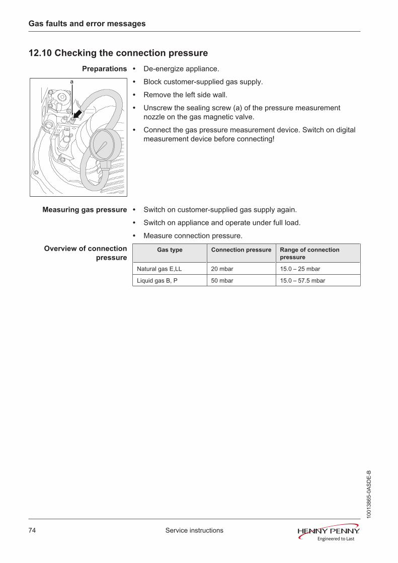
Gas faults and error messages
74 Service instructions
12.10 Checking the connection pressure
Preparations
a
• De-energize appliance.
• Block customer-supplied gas supply.
• Remove the left side wall.
• Unscrew the sealing screw (a) of the pressure measurementnozzle on the gas magnetic valve.
• Connect the gas pressure measurement device. Switch on digitalmeasurement device before connecting!
Measuring gas pressure • Switch on customer-supplied gas supply again.
• Switch on appliance and operate under full load.
• Measure connection pressure.Overview of connection
pressureGas type Connection pressure Range of connection
pressure
Natural gas E,LL 20 mbar 15.0 – 25 mbar
Liquid gas B, P 50 mbar 15.0 – 57.5 mbar
1001
3865
-0AS
DE-
B
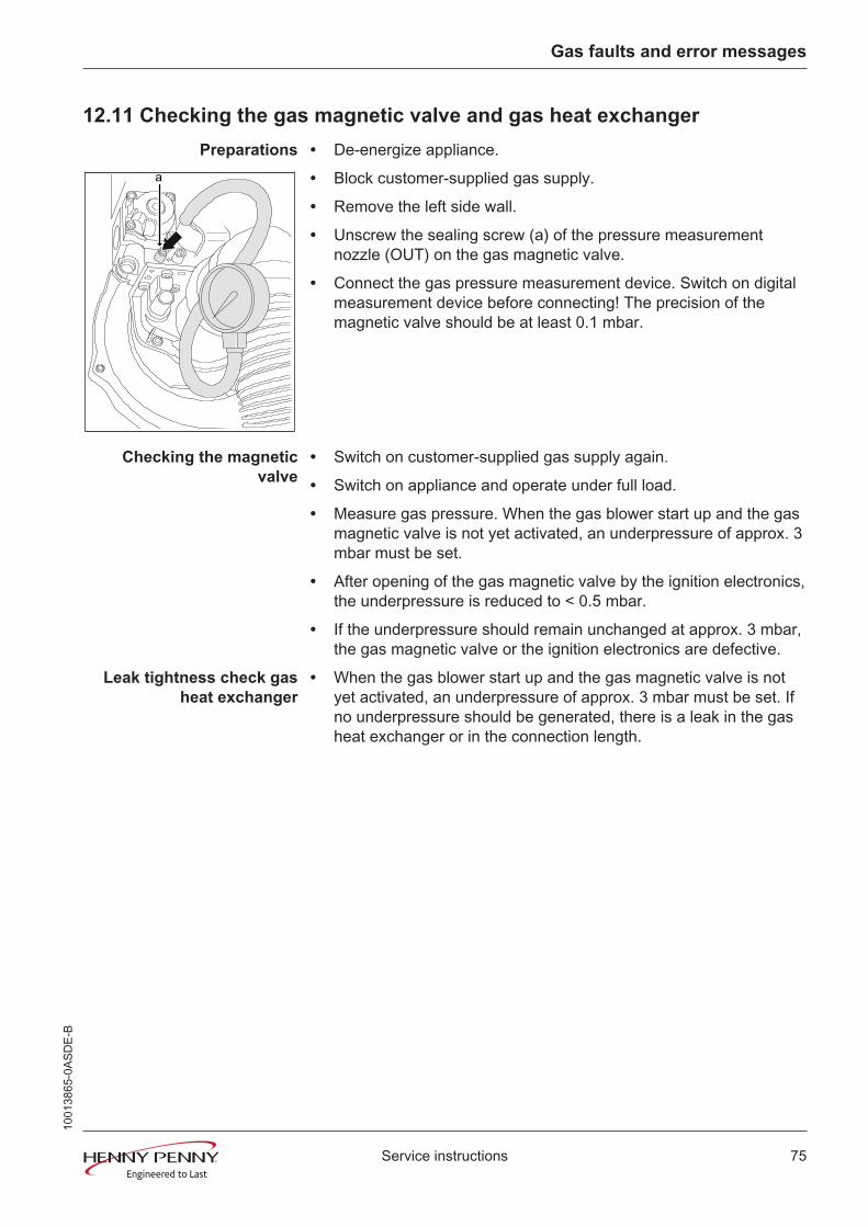
Gas faults and error messages
75Service instructions
12.11 Checking the gas magnetic valve and gas heat exchanger
Preparations
a
• De-energize appliance.
• Block customer-supplied gas supply.
• Remove the left side wall.
• Unscrew the sealing screw (a) of the pressure measurementnozzle (OUT) on the gas magnetic valve.
• Connect the gas pressure measurement device. Switch on digitalmeasurement device before connecting! The precision of themagnetic valve should be at least 0.1 mbar.
Checking the magneticvalve
• Switch on customer-supplied gas supply again.
• Switch on appliance and operate under full load.
• Measure gas pressure. When the gas blower start up and the gasmagnetic valve is not yet activated, an underpressure of approx. 3mbar must be set.
• After opening of the gas magnetic valve by the ignition electronics,the underpressure is reduced to < 0.5 mbar.
• If the underpressure should remain unchanged at approx. 3 mbar,the gas magnetic valve or the ignition electronics are defective.
Leak tightness check gasheat exchanger
• When the gas blower start up and the gas magnetic valve is notyet activated, an underpressure of approx. 3 mbar must be set. Ifno underpressure should be generated, there is a leak in the gasheat exchanger or in the connection length.
1001
3865
-0AS
DE-
B

Gas faults and error messages
76 Service instructions
12.12 Checking the electrodes
Preparations • Remove the left side wall.
Overview
X115
610
230V230V
N 24-28V, ~1,4A
3 µAa b c d
F1 3,15A
a Ignition electronics A10 / A20 c Ionization electrode (flamemonitoring) B100 / B200
b Transformer T10 / T20 d Glow electrode F10 / F20
12.12.1 Glow electrode
Preparations • On the Service menu, select the Gas CO2 calibration and start.
• Only begin troubleshooting when Gas request lights up green.
INFORMATION The transformer (b) is only supplied with voltage with active gas request. Theglow electrode can be checked visually through the sight glass on the gasburner.
Troubleshooting Check output voltage on the transformer.The voltage is 24 V.
Check the current consumption of the glow electrode. This mustbe at least 1.4 A.Check fuse F1 on the transformer.
The fuse has blown.Replace fuse. Repeat test and replace glow electrode ifnecessary.Check supply voltage at the transformer.
No voltage present = Check neutral conductor. Replacetransformer.Voltage present = Replace ignition electronics.
1001
3865
-0AS
DE-
B

Gas faults and error messages
77Service instructions
12.12.2 Ionization electrode
Preparations • On the Service menu, select the Gas CO2 calibration and start.
• Only begin troubleshooting when Gas request lights up green.
Troubleshooting With active gas burner (gas flame), the ionization stream of the flamemonitoring (d) must be at least 3 µA. In addition to the ionizationelectrode, the ignition electronics (a) can also be the cause of theerror.
1001
3865
-0AS
DE-
B

Gas faults and error messages
78 Service instructions
1001
3865
-0AS
DE-
B

CopyrightAll rights to text, graphics and picturesin this documentation are held by MKNMaschinenfabrik Kurt NeubauerGmbH & Co. KG. Distribution orduplication is exclusively permissiblesubject to a written consent of MKN.Copyright by MKN MaschinenfabrikKurt Neubauer GmbH & Co. KG
ManufacturerCopyright by MKN MaschinenfabrikKurt Neubauer GmbH & Co. KGHalberstaedter Strasse 2aD-38300 WolfenbuettelTelephone 0 53 31 / 89-0Telefax 0 53 31 / 89-280
*10013865-0ASDE-B*