Elgin/ Lake Huron SCADA Upgrades SCADA … · 203 EQUIPMENT AND SCADA SIGNAL CODING ... List...
38
EA LH SCADA Standards 200 v7 The only actual version of this document is the web site, not a printed version. 1 of 38 If this printout is more than 24 hours old, check web site for a more current version. Printed 3/1/2013 Elgin/Lake Huron SCADA Upgrades SCADA Standards Section 200 Preliminary Design Version 7 Elgin/ Lake Huron SCADA Upgrades SCADA Standards Section 200 Preliminary Design Version Date Description of Revision v1 March 7, 2006 Preliminary Draft v2 March 22, 2006 Second Draft v3 December 2006 Tender Version v4 January 2008 Construction Phase Updates 1 v4_5 May 2009 During Construction Minor Updates v5 May 2010 Final Draft v6 January 2011 As Recorded v7 March 2013 Minor update 1.2.1
Transcript of Elgin/ Lake Huron SCADA Upgrades SCADA … · 203 EQUIPMENT AND SCADA SIGNAL CODING ... List...

EA LH SCADA Standards 200 v7 The only actual version of this document is the web site, not a printed version. 1 of 38 If this printout is more than 24 hours old, check web site for a more current version. Printed 3/1/2013
Elgin/Lake Huron SCADA Upgrades SCADA Standards
Section 200 Preliminary Design Version 7
Elgin/ Lake Huron SCADA Upgrades SCADA Standards
Section 200 Preliminary Design
Version Date Description of Revision
v1 March 7, 2006 Preliminary Draft
v2 March 22, 2006 Second Draft
v3 December 2006 Tender Version
v4 January 2008 Construction Phase Updates 1
v4_5 May 2009 During Construction Minor Updates
v5 May 2010 Final Draft
v6 January 2011 As Recorded
v7 March 2013 Minor update 1.2.1

EA LH SCADA Standards 200 v7 The only actual version of this document is the web site, not a printed version. 2 of 38 If this printout is more than 24 hours old, check web site for a more current version. Printed 3/1/2013
Elgin/Lake Huron SCADA Upgrades SCADA Standards
Section 200 Preliminary Design Version 7
Elgin/Lake Huron SCADA Upgrades SCADA Standards
Section 200 Preliminary Design
Table of Contents
201 PRELIMINARY DESIGN GENERAL REQUIREMENTS ................................................................................. 4
1. GENERAL SCADA DESIGN DETAILS .................................................................................................................4 1.1 Existing Documents and Record Drawings ...............................................................................................4 1.2 Equipment Redundancy and Selection .....................................................................................................4 1.3 Approvals ..................................................................................................................................................4
2. SUMMARY OF SCADA PRELIMINARY DESIGN DELIVERABLES .............................................................................5
202 SCADA DESIGN PHILOSOPHY ..................................................................................................................... 6
1. DEGREE OF AUTOMATION .................................................................................................................................6 2. SCADA PERFORMANCE TARGETS ....................................................................................................................6 3. SCADA ARCHITECTURE ..................................................................................................................................6
3.1 WTP SCADA System ................................................................................................................................6 3.2 Outstation SCADA System .......................................................................................................................6 3.3 Inter-WAN Links ........................................................................................................................................6 3.4 Historical Data Storage .............................................................................................................................6
203 EQUIPMENT AND SCADA SIGNAL CODING ............................................................................................... 7
1. GENERAL REQUIREMENTS ................................................................................................................................7 1.1 Overview ...................................................................................................................................................7 1.2 Major Equipment Codes ............................................................................................................................7
1.2.1 Fragment 1- Facility ............................................................................................................................7 1.2.2 Fragment 2- Equipment Identifier Codes ............................................................................................9 1.2.3 Fragment 3 – Equipment Number ................................................................................................... 12
1.3 Minor Equipment and Instrument Codes................................................................................................ 12 1.3.1 Fragment 1-3 ................................................................................................................................... 12 1.3.2 Fragment 4 Minor Device Code ....................................................................................................... 12
1.4 Field Signal I/O Codes ........................................................................................................................... 15 1.4.1 Fragments 1-4 ................................................................................................................................. 15 1.4.2 Fragment 5- PLC Field I/O ............................................................................................................... 16
2. PLC SIGNALS ............................................................................................................................................... 19 2.1 MicroLogix Tagnames ............................................................................................................................ 19
2.1.1 Fragments 1-4 ................................................................................................................................. 19 2.1.2 Fragment 5- PLC Field I/O ............................................................................................................... 19 2.1.3 Fragment 6- PLC Field I/O Attribute ................................................................................................ 19 2.1.4 Example ........................................................................................................................................... 19
2.2 Compact Logix and Control Logix Tagnames ........................................................................................ 19 2.2.1 Fragments 1-4 ................................................................................................................................. 20 2.2.2 Fragment 5- PLC Field I/O ............................................................................................................... 20 2.2.3 Fragment 6- PLC Field I/O Attribute ................................................................................................ 20 2.2.4 Fragment 7- Internal PLC Subroutine .............................................................................................. 20 2.2.5 Example ........................................................................................................................................... 20
2.3 SCADA HMI Tagnames ......................................................................................................................... 20 2.3.1 Fragments 1-4 ................................................................................................................................. 20 2.3.2 Fragment 5- PLC Field I/O ............................................................................................................... 20 2.3.3 Fragment 6- PLC Field I/O Attribute ................................................................................................ 20 2.3.4 Fragment 7- Internal PLC Subroutine .............................................................................................. 20 2.3.5 Fragment 8- PLC Number ............................................................................................................... 21 2.3.6 Example ........................................................................................................................................... 21
2.4 Fragment 5, 6, 7, and 8 Codes .............................................................................................................. 21

EA LH SCADA Standards 200 v7 The only actual version of this document is the web site, not a printed version. 3 of 38 If this printout is more than 24 hours old, check web site for a more current version. Printed 3/1/2013
Elgin/Lake Huron SCADA Upgrades SCADA Standards
Section 200 Preliminary Design Version 7
2.5 Typical Device Tagnames ...................................................................................................................... 25 2.6 Control Wiring Labeling .......................................................................................................................... 27 2.7 Control Panel Labeling ........................................................................................................................... 27
204 PROCESS & INSTRUMENTATION DRAWINGS (P&ID’S) .......................................................................... 28
1. GENERAL ..................................................................................................................................................... 28 1.1 Purpose of Standard .............................................................................................................................. 28 1.2 ISA Reference Standard ........................................................................................................................ 28 1.3 Purpose of P&ID ..................................................................................................................................... 28 1.4 Drawing Phases ..................................................................................................................................... 29 1.5 Scope of Drawings ................................................................................................................................. 30 1.6 Terminology ............................................................................................................................................ 30 1.7 Process Layout ....................................................................................................................................... 30 1.8 Tank System Layout............................................................................................................................... 31 1.9 Mechanical Equipment Layout ............................................................................................................... 31 1.10 Controls Layout .................................................................................................................................. 31
1.10.1 Control Levels .............................................................................................................................. 31 1.10.2 Package Panels ........................................................................................................................... 31 1.10.3 Custom Panels ............................................................................................................................ 32 1.10.4 Control Signals ............................................................................................................................ 32 1.10.5 Interlocks...................................................................................................................................... 32 1.10.6 Typifying ....................................................................................................................................... 32
1.11 Overviews and Details ....................................................................................................................... 33 1.11.1 Plant or System Overview ........................................................................................................... 33 1.11.2 Unit Process (Area) Overviews.................................................................................................... 33 1.11.3 Device Overviews ........................................................................................................................ 33 1.11.4 Redundant Information ................................................................................................................ 33
1.12 Symbol and Legend Sheets ............................................................................................................... 33 1.12.1 Primary Element Symbols ........................................................................................................... 33 1.12.2 Miscellaneous Symbols ............................................................................................................... 33 1.12.3 Actuator Symbols ......................................................................................................................... 33 1.12.4 Instrument and Function Symbols ............................................................................................... 34 1.12.5 Flow Stream Identification ........................................................................................................... 34 1.12.6 Equipment Tagging ...................................................................................................................... 34 1.12.7 Flow Stream and Instrument Line Symbols ................................................................................. 34 1.12.8 Explanatory Notations .................................................................................................................. 35
205 PROCESS NARRATIVES .............................................................................................................................. 36
1. GENERAL REQUIREMENTS ............................................................................................................................. 36 1.1 Content ................................................................................................................................................... 36 1.2 Process Descriptions.............................................................................................................................. 36
1.2.1 Operation Description ...................................................................................................................... 36 1.2.2 Control Description .......................................................................................................................... 38

EA LH SCADA Standards 200 v7 The only actual version of this document is the web site, not a printed version. 4 of 38 If this printout is more than 24 hours old, check web site for a more current version. Printed 3/1/2013
Elgin/Lake Huron SCADA Upgrades SCADA Standards
Section 200 Preliminary Design Version 7
201 Preliminary Design General Requirements
1. General SCADA Design Details
1.1 Existing Documents and Record Drawings 1. The Owner will provide copies of available record drawings, reports, and other documents pertaining to the
project. The Consultant shall note that changes may have been made over time without updating the documents or record drawings. Prior to commencement of the pre-design, the Consultant shall review the existing background information, as well as conduct a site review at the facility to confirm changes or omissions, if any, in the record drawings. The expected level of the site review includes a walk through the facility and visual observations. The Consultant shall record its findings and advise the Joint Board of any significant changes or omissions in the record drawings.
2. Any redesign work required due to the Consultant’s failure to review documents or record drawings will be at
the Consultant’s own cost. 3. Review scope of current, parallel projects and identify potential impacts on the project. Ensure that any
potential impacts/conflicts are identified and discussed with the project team.
1.2 Equipment Redundancy and Selection 1. The Consultant shall ensure that the level of redundancy for process and/or equipment at all facilities meets
the Certificate of Approval criteria, operating objectives, and the functionality of the associated process equipment. The Owner has adopted, in principle, a policy to provide firm capacity for major processes and equipment. Under the policy for each process one or two process units could be offline for maintenance and repair, while still complying will the Certificate of Approval, as well as other provincial or federal regulations.
2. Discuss with Owner’s staff their preferences for equipment selection. Identify suppliers and recommend
equipment based on the following: best performance, reliability, flexibility, availability, life cycle costs, ease of maintenance, expandability, spatial requirements and supplier/owner references with respect to service in existing installations. List features, benefits, as well as advantages and disadvantages of the selected equipment, including information on equipment delivery and its impact on construction timelines. Except for proprietary equipment, consider at least three suppliers for each component, whenever possible.
3. In consultation with the Owner, prepare equipment list and data sheets for inclusion in the pre-design report.
Ensure that the selected equipment/system can be fully automated and is suitable for unattended operation, where appropriate.
1.3 Approvals 1. During pre-design, the Consultant shall determine the project specific approvals and co-ordinate the process
with the Owner and the approval agencies. 2. If applicable, conduct pre-consultation with the Ministry of the Environment prior to submitting an application
for the Certificate of Approval. 3. Near the conclusion of the pre-design phase, identify if a pre-start health & safety review will be required at
the conclusion of the design phase of the project.

EA LH SCADA Standards 200 v7 The only actual version of this document is the web site, not a printed version. 5 of 38 If this printout is more than 24 hours old, check web site for a more current version. Printed 3/1/2013
Elgin/Lake Huron SCADA Upgrades SCADA Standards
Section 200 Preliminary Design Version 7
2. Summary of SCADA Preliminary Design Deliverables
1. The following provides a list of deliverables upon completion of the pre-design. The Consultant shall note that the RFP may contain additional project specific deliverables or delete some accordingly. a. SCADA Preliminary Design Report b. Preliminary P&ID’s c. Process Narratives
EA LH SCADA Standards 200 v7 The only actual version of this document is the web site, not a printed version. 6 of 38 If this printout is more than 24 hours old, check web site for a more current version. Printed 3/1/2013
Elgin/Lake Huron SCADA Upgrades SCADA Standards
Section 200 Preliminary Design Version 7
202 SCADA Design Philosophy
1. Degree of Automation 1. Unless specifically instructed in the Request for Proposal that automation in the facility is not required, all
processes shall be fully automated, allowing for unattended operation of the system.
2. SCADA Performance Targets 2. The following SCADA Network Performance targets have been established. As part of the initial design
activities for each project, the design should evaluate and document the current SCADA performance. In the Predesign report, the designer should identify any required SCADA infrastructure upgrades so that, at the end of the related construction activities, the SCADA Performance targets will continue to be met.
a. In-plant alarms displayed on SCADA HMI in <2 seconds. b. In-plant responses to commands on SCADA HMI in <3 seconds. c. Remote facility alarms displayed on SCADA HMI in <5 seconds. d. Remote facility responses to commands displayed on SCADA HMI in <10 seconds. e. SCADA server minimum spare capacity >25% (RAM capacity, HD, and CPU performance). f. PLC CPU minimum spar capacity >50%. g. PLC field I/O minimum spare capacity >20%. h. Network switch ports minimum spare capacity >20%. i. Network traffic minimum spare capacity >50% during normal operating conditions. j. For all in-plant trunk fibre cables, a minimum 20% spare fibres, but all must be terminated in the patch
panels. 3. For the continuous, efficient monitoring of the network traffic, the OPC Server monitoring software is installed.
3. SCADA Architecture
3.1 WTP SCADA System 1. The overall SCADA Architecture consists of dual, hot standby Front End Controllers (FECs) connected to
remote I/O racks across the plants. For major mechanical equipment, including the high and low lift pumps, individual remote I/O racks are required.
2. The FECs are connected to dual hot standby SCADA Servers, with key historical data transferred to the
historical SQL database. 3. All new field I/O and I/O racks must be integrated into this architecture.
3.2 Outstation SCADA System 1. Each outstation must be capable of operating safely, independently, when the WAN link fails. Therefore an
PLC and limited local data collection is required.
3.3 Inter-WAN Links 2. Real time links to the secondary SCADA systems are used to transfer the critical, real time alarm between the
Joint Board, Primary Water Supply SCADA System and the Secondary SCADA Systems. This is accomplished by using hardwired I/O between two PLC at the selected inter-WAN link site.
3. The key data that must be transferred from the secondary systems are tower/reservoir levels, major flow
meters, key water quality parameters. The key data that must be transferred from the Joint Board to the secondary systems are major flow meters.
3.4 Historical Data Storage 1. All key operating parameter are transferred to the SCADA Historian, SQL database.
EA LH SCADA Standards 200 v7 The only actual version of this document is the web site, not a printed version. 7 of 38 If this printout is more than 24 hours old, check web site for a more current version. Printed 3/1/2013
Elgin/Lake Huron SCADA Upgrades SCADA Standards
Section 200 Preliminary Design Version 7
203 Equipment and SCADA Signal Coding
1. General Requirements
1.1 Overview 2. The objective of the Joint Board coding system is to ensure consistency in equipment labeling across all
facilities. The following is a brief description of how the equipment and SCADA signal acronyms are composed and what each fragment of the acronym represents.
3. A summary of all codes found in the Joint Board system follows, broken down by fragments. Any clarification
required with respect to the coding system will be provided by the Joint Board. No codes are to be used that are not identified in the following tables without prior approval from the Joint Board.
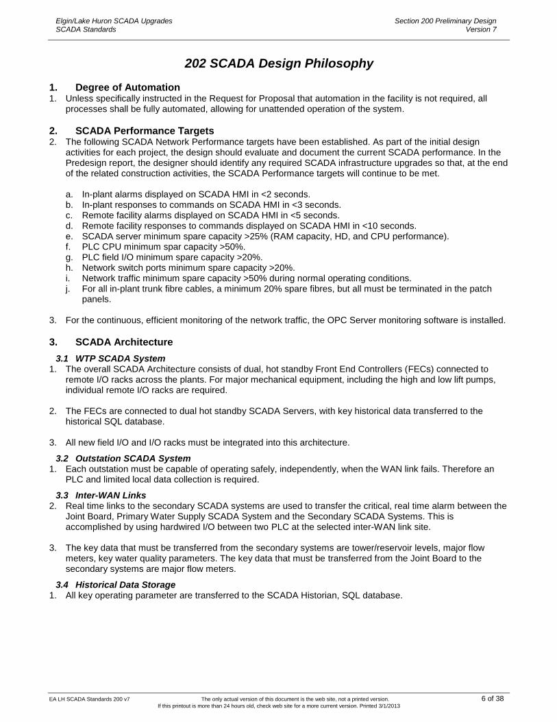
1.2 Major Equipment Codes 1. The equipment and instrument codes are as follows.
Tag Fragment CCC CCC CC
Fragment No. 1 2 3
Explanation of Characters: 1. 3 Characters: Represents facility 2. 3 Characters: Represents major mechanical equipment 3. 2 Characters: Represents number of mechanical equipment
1.2.1 Fragment 1- Facility
Fragment 1 is a three character code representing the facility. Refer to the following table.
Elgin Area Water Supply Locations
Acronym Facility
EAW Elgin Area Water Treatment Plant
EAL Elgin Area Low Lift Pump Station
EFR Fruit Ridge Surge Facility
EMP Elgin-Middlesex Pump Station
CE4 Port Stanley Valve Chamber (inter-WAN site)
PB3 Port Burwell Valve Chamber MV1/MV2 (inter-WAN site)
EPA Elgin Pipeline A
EPB Elgin Pipeline B
EPI Elgin Pipeline Interconnect
Lake Huron Water and Waste Water Locations
Acronym Facility
LHL Lake Huron Low Lift
LHW Lake Huron Water Plant
LH4 McGillvray Reservoir (Ausable)
LH3 B Line North Valve Chamber (including Exeter-Hensall Monitoring Station 1)
LH2 B Line South Valve Chamber
LH6 Monitoring Station MS1
LH7 Monitoring Station MS2
NM1 Mount Carmel Reservoir
LH5 Arva Reservoir
MC2 Denfield Booster Station

EA LH SCADA Standards 200 v7 The only actual version of this document is the web site, not a printed version. 8 of 38 If this printout is more than 24 hours old, check web site for a more current version. Printed 3/1/2013
Elgin/Lake Huron SCADA Upgrades SCADA Standards
Section 200 Preliminary Design Version 7
LU2 Lucan Booster Station/Link From Lucan Tower
Exeter/Hensall Pipeline Sites
EH1 Exeter Hensall Reservoir and Booster Station
EH2 Exeter Hensall Monitoring Station 2 (Dashwood)
EH3 Exeter Hensall Monitoring Station 3 (Hensall)
EH4 Exeter Hensall Monitoring Station 4
SH1 Exeter Water Tower, South Huron
BW1 Hensall Water Tower, Blue Water
Komoka Mt. Brydges Pipeline Sites
KB1 Komoka-Mt. Brydges Booster Pumping Station
KM1 Coldstream/Medway Monitoring Station #1
KM2 Falconbridge/Springwell Monitoring Station #2
APAM Water and Waste Water Locations
Acronym Facility
AY4 Aylmer Tower
AY3 Valve Chamber 16
AY2 Valve Chamber 13
PB4 Chamber E034 (Lakeview)
TM2 Copenhagen Booster Station
PB2 Port Burwell Tower
PB3 Port Burwell Chamber MV1/MV2
AY9 Aylmer Main Sewage Pump Station
St. Thomas Water and Waste Water Locations
Acronym Facility
WD3 Albert Roberts Booster Station
WS4 Ford Tower
WS1 Ford Meter Chamber
WD1 West Chamber
WS2 Southwold
WS3 Wellington PRV
SO9 Axford SPS
SO2 Confederation SPS
SC2 Crescent SPS
SO1 Dalewood SPS
SO3 Harper SPS
SC1 Lynhurst SPS
SO8 Parkside SPS
SO6 St. George SPS
SS7 Sunset SPS
SS4 Wolf SPS
SC3 Woodland SPS
SO5 Woodworth SPS
Central Elgin Area Water and Waste Water Locations
Acronym Facility
CE7 Belmont Water Tower
CE3 Belmont Waterworks
CE2 Port Stanley Water Tower
CE1 Port Stanley Chamber 1

EA LH SCADA Standards 200 v7 The only actual version of this document is the web site, not a printed version. 9 of 38 If this printout is more than 24 hours old, check web site for a more current version. Printed 3/1/2013
Elgin/Lake Huron SCADA Upgrades SCADA Standards
Section 200 Preliminary Design Version 7
CE4 Port Stanley Chamber 4
CE6 Sunset PRV
C71 Belmont Station 71 SPS
C72 Belmont Station 72 SPS
C73 Belmont Station 73 SPS
C51 Port Stanley Station 51 SPS
C53 Port Stanley Station 53 SPS
C54 Port Stanley Station 54 SPS
C55 Port Stanley Station 55 SPS
C56 Port Stanley Station 56 SPS
C52 Port Stanley Station Train Station SPS
CP2 Port Stanley Station 56 WPCP
CP1 Belmont WPCP
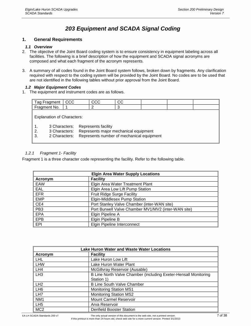
1.2.2 Fragment 2- Equipment Identifier Codes
1. Fragment 2 is a three character code representing the acronym for the mechanical equipment or area. Refer to the following table. For instruments associated with the building, such as flood alarms, Fragment 2 should be the building (BLD) code, plus the building number. Then Fragment 4 can be the instrument code for instruments associated with a common area or general piping area, not with a specific major mechanical device, Fragment 2 should be the area or piping header codes, such as ―BWH‖, backwash header.
CODE DESCRIPTION
ACN Air Conditioner
ACP Air Compressor
ADS Absorber
ADT Alum Day Tank
AER Aerator
AFP Alum Feed Pump
AHU Air Handling Unit
ALS Alum Storage Tank
ALP Alarm Panel Indication
ATF Alum Transfer Pump
ATS Automatic Transfer Switch
BLD Building
BLO Blower
BSK Basket Strainer
BSP Booster Pump
BWL Backwash Line
BWH Backwash Header
BWP Backwash Pump
BWT Backwash Holding Tank
CBP Chlorine Booster Pump
CDT Chlorine Day Tank
CFP Caustic Soda Pump
CHL Chlorinator
CHP Chlorine Pump
CLF Clarifier
CLR Chlorine Room
CLW Clearwell
CMP Compressor
CNV Control Valve
CPP Cat 5 Patch Panel
CPU Computer
CRN Crane
CST Chlorine Storage Tank
EA LH SCADA Standards 200 v7 The only actual version of this document is the web site, not a printed version. 10 of 38 If this printout is more than 24 hours old, check web site for a more current version. Printed 3/1/2013
Elgin/Lake Huron SCADA Upgrades SCADA Standards
Section 200 Preliminary Design Version 7
CODE DESCRIPTION
CTP Chlorine Transfer Pump
DCV Decant Valve
DDT Fuel Day Tank
DFP Diesel Fuel Pump
DFT Diesel Fuel Tank
DTF Fuel Day Tank
DHR Disk Header
DHU Dehumidifier
DRN Drain
DSV Desludge Valve
DTR Day Tank
DWL Drywell
EAL_BLD01 Main Building
EAL_BLD02 Zebra Mussel Building
EAW_BLD01 Flocculation
EAW_BLD02 Chlorine
EAW_BLD03 Filter/HL/Clearwell/Main Building/
EAW_BLD04 Surge Tank
EAW_BLD05 Generator Building
EPE Emergency Power Equipment
EWL Effluent Water Line
EWP Effluent Water Pump
EWS Effluent Water Strainer
EXF Exhaust Fan
FDT Fluoride Day Tank
FIL Water Filter
FLC Flocculators
FLP Fluoride Pump
FLT Filters
FMC Flash Mixing Chamber
FPP Fiber Patch Panel
FRL Network Firewall
FTK Fluoride Tank
FTP Fluoride Transfer Pump
GAF Gas Furnace
GBT Gravity Belt Thickener
GCL Grit Classifier
GCP Grit Chamber Pump
GEN Generator
GFV Gravity Flow Valve
GRF Gravity Filter
GRI Grinder
GRP Grit Wash Pump
GSP Grit Separator
GTE Gate
GWP Grit Wash Pump
HCT Sodium Hypochlorite Tank
HLP High Lift Pump
HWB Hot Water Boiler
HWP Hot Water Pump
HYD Yard Hydrant
INJ Injector
INT Intake
IWL Influent Water Line
LLP Low Lift Pump

EA LH SCADA Standards 200 v7 The only actual version of this document is the web site, not a printed version. 11 of 38 If this printout is more than 24 hours old, check web site for a more current version. Printed 3/1/2013
Elgin/Lake Huron SCADA Upgrades SCADA Standards
Section 200 Preliminary Design Version 7
CODE DESCRIPTION
MBR Main Breaker
MCC Motor Control Centre
MHL Manhole
NGH Natural Gas Headerline
NGH Natural Gas Headerline
PAP PAC Feed Pump
PAT PAC Transfer Pump
PDT Polymer Day Tank
PFR Power Feeder
PKL Parking Lot
PLP Plant Service Water Pump
POP Polymer Feed Pump
PST Pneumatic Surge Tanks
PTK PAC Storage Tank
PTP Polymer Transfer Pump
PTR Power Transformer
RCP Recirculation Pump
RES Reservoir
RFG Refrigerator
RIO Remote I/O
PLC Remote Processing Unit
RSP Raw Sludge Pump
RSV Reservoir
RTK Recirculation Tank
RTR Network Router
SAM Automatic Sampler
SAP Sample Pump
SBV Sludge Blowdown Valve
SCB Scrubber
SCC Screw Conveyor
SCP SCADA Control Panel
SEC Sediment Water Conduit
SED Sedimentation Tank
SHP Sodium Hypochlorite Pump
SLC Sludge Collector
SLP Sewage Pump
SMP Sump Pump
SMT Sump Tank
SPE Standpipe
SPT Septic Tank
SRV Surge Relief Valve
SSV Surge Suppressor Valve
STR Storage Room
STT Settling Tank
SUT Surge Tank
SWI Network Switch
SWG Switch Gear
SWP Surface Wash Pump
TFP Fuel Transfer Pump
TSC Traveling Screen
TSR Transformer
UFT 1-9 Underground Fuel Tank
UHT Unit Heater
UVS U.V. System
UWP Unwatering Pump

EA LH SCADA Standards 200 v7 The only actual version of this document is the web site, not a printed version. 12 of 38 If this printout is more than 24 hours old, check web site for a more current version. Printed 3/1/2013
Elgin/Lake Huron SCADA Upgrades SCADA Standards
Section 200 Preliminary Design Version 7
CODE DESCRIPTION
VAP Vacuum Pump
VCH Valve Chamber
WLL Well
WWL Wetwell
WAP Wireless Access Point
1.2.3 Fragment 3 – Equipment Number
1. Fragment 3 is a two character, equipment number ranging from 01 to 99. In special situations ―00‖ is used to identify valves and instruments related to the common piping header, or area.
2. The following example is provided: EA1_HLP01 where: EA1 = Elgin Area Water Treatment Plant HLP = High Lift Pump 01 = Pump Number 01 3. On the mechanical, process, and electrical drawings, fragment 1 can be referenced with a note, where
appropriate. The other fragments are to be indicated beside each equipment symbol on the drawing. Underscores are to be provided on the drawings, as indicated in the examples above.
1.3 Minor Equipment and Instrument Codes 1. For motorized valves, instrumentation, and other minor equipment that is related to a major piece of process
mechanical equipment, a suffix code is added to the main equipment code. This then relates and groups these minor devices together with their related major device. For instruments associated with the building, such as flood alarms, Fragment 2 should be the building (BLD) code, plus the building number. Then Fragment 4 can be the instrument code for instruments associated with a common area or general piping area, not with a specific major mechanical device, Fragment 2 should be the area or piping header codes, such as ―BWH‖, backwash header.
2. For situations such as multiple motorized valves on a discharge header, the valve codes should be related to
the upstream group of pumps, based on the pump number 00, which represents the group of pumps. For example, if a group of motorized valves are downstream of high lift pumps 1-4 (HLP01 to HLP04), then the appropriate valve codes are HLP00_C01, PSP00_C02, etc.
Tag Fragment CCC CCC CC CCC
Fragment No. 1 2 3 4
Explanation of Characters: 1. 3 Characters: Represents facility 2. 3 Characters: Represents mechanical equipment 3. 2 Characters: Represents number of mechanical equipment 4. 3 Characters: Represents the minor device tag and number
1.3.1 Fragment 1-3
1. Fragments 1-3 are consistent with the equipment coding scheme noted above.
1.3.2 Fragment 4 Minor Device Code
1. Fragment 4 is a three character code that specifies the minor equipment. These codes, where applicable, are also shown on the plant P&ID’s to identify manual valves and similar items with no electrical connections.
2. The following example is provided:

EA LH SCADA Standards 200 v7 The only actual version of this document is the web site, not a printed version. 13 of 38 If this printout is more than 24 hours old, check web site for a more current version. Printed 3/1/2013
Elgin/Lake Huron SCADA Upgrades SCADA Standards
Section 200 Preliminary Design Version 7
EA1_HLP01 _PIT where: EA1 = Elgin Area Water Treatment Plant HLP = High Lift Pump 01 = Pump Number 01 PIT = Pressure Indicating Transmitter/or use PT1 if multiple transmitters nearby. 3. On the mechanical, process, and electrical drawings, fragments 1 and 2 can be referenced with a note, where
appropriate. The other fragments are to be indicated beside each instrument /equipment symbol on the drawing. Underscores are to be provided, as indicated in the example above.
Fragment 4 Codes
Acronym Description
Instruments
AHH Analyzer Switch High High (Hazardous Gas, Chlorine)
AI1-9 Analyzer Indicator 1-9
ALL Analyzer Switch Low Low (Hazardous Gas, Chlorine)
APB Acknowledge Push Button
ASH Analyzer Switch High (Hazardous Gas, Chlorine)
ASL Analyzer Switch Low (Hazardous Gas, Chlorine)
AT1-9 Analyzer Indicating Transmitters 1-9 (Hazardous Gas, Chlorine)
ATS Automated Transfer Switch (Related to a particular Generator)
CB1-9 Power equipment protection devices 1-9 (Breakers)
CS1-9 Cluster Switch
DHH Density Switch High High (Turbidity)
DI1-9 Density Indicator (Turbidity)
DLL Density Switch Low Low (Turbidity)
DO1-9 Dissolved Oxygen Probes 1-9
DSH Density Switch High (Turbidity)
DSL Density Switch Low (Turbidity)
DT1-9 Density Indicating Transmitters 1-9 (Sludge and Turbidity)
FHH Flow Switch High High
FI1-9 Flow Indicator
FLL Flow Switch Low Low
FSH Flow Switch High
FSL Flow Switch Low
FT1-9 Flow Indicating Transmitters 1-9
FVN Full Voltage Non reversing Starter
HS1-9 Hand Switches 1-9 related to Major Device
IS1-9 Electrical Isolation Disconnect Switches 1-9
JT1-9 Voltage or Power Monitoring
LHH Level Switch High High
LI1-9 Level Indicator
LLL Level Switch Low Low
LS1-9 Level Switches 1-9
LSH Level Switch High
LSL Level Switch Low
LT1-9 Level Indicating Transmitters
MD1-9 Mandown 1-9
MS1-9 Motion Sensors
MT1-9 Motor Temperature /Trip 1-9

EA LH SCADA Standards 200 v7 The only actual version of this document is the web site, not a printed version. 14 of 38 If this printout is more than 24 hours old, check web site for a more current version. Printed 3/1/2013
Elgin/Lake Huron SCADA Upgrades SCADA Standards
Section 200 Preliminary Design Version 7
MX1-9 Tank Mixers 1-9
PFC Power Factor Correction Capacitors MS 1-9 Motion Sensor
PHH Pressure Switch High High
PI1-9 Pressure Indicator
PLL Pressure Switch Low Low
PM1-9 Power Monitoring Units 1-9
PSH Pressure Switch High
PSL Pressure Switch Low
PT1-9 Pressure Indicating Transmitters 1-9
RVS Reduced Voltage Starter
SHH Speed Switch High High
SI1-9 Speed Indicator
SLL Speed Switch Low Low
SSH Speed Switch High
SSL Speed Switch Low
ST1-9 Speed Indicating Transmitters 1-9
SV1-9 Solenoid Valve 1-9
THH Temperature Switch High High
TI1-9 Temperature Indicator
TLL Temperature Switch Low Low
TM1-9 Timers 1-9
TSD Electrical Surge Suppression Device
TSH Temperature Switch High
TSL Temperature Switch Low
TT1-9 Temperature Indicating Transmitters 1-9
VHH Vibration Switch High High
VAC Vaccum
VI1-9 Vibration Indicator
VLL Vibration Switch Low Low
VSH Vibration Switch High
VSL Vibration Switch Low
VT1-9 Vibration Indicating Transmitters 1-9
WT1-9 Weigh Scales 1-9
Valves
C01-CZZ Motorized Control Valves 01-99 related to a major device, or group of devices
CV1-CV9 Check Valves
OC1-OC9 Discharge motorized Control Valve on major pumps, blowers, and similar devices
M01-M99 Monitored valves
PV1-PV9 Pressure reducing Valves
SC1-SC9 Suction motorized Control Valve on major pumps, blowers, and similar devices
V01-V99 Manual valves related to a major device, or group of devices
Water Filters
AC1-9 Air Backwash Motorized Control Valves 1-9
DC1-9 Drain Motorized Control Valves 1-9
IC1-9 Inlet Motorized Control Valves/Gates 1-9
OC1-9 Outlet Motorized Control Valves/Gates 1-9
SC1-9 Surface Wash Control Valves 1-9
WC1-9 Water Backwash Motorized Control Valves 1-9
Motor Sensors
EA LH SCADA Standards 200 v7 The only actual version of this document is the web site, not a printed version. 15 of 38 If this printout is more than 24 hours old, check web site for a more current version. Printed 3/1/2013
Elgin/Lake Huron SCADA Upgrades SCADA Standards
Section 200 Preliminary Design Version 7
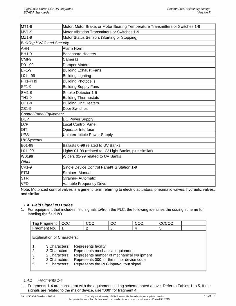
MT1-9 Motor, Motor Brake, or Motor Bearing Temperature Transmitters or Switches 1-9
MV1-9 Motor Vibration Transmitters or Switches 1-9
MZ1-9 Motor Status Sensors (Starting or Stopping)
Building HVAC and Security
AHN Alarm Horn
BH1-9 Baseboard Heaters
CMI-9 Cameras
D01-99 Damper Motors
EF1-9 Building Exhaust Fans
L01-L99 Building Lighting
PH1-PH9 Building Photocells
SF1-9 Building Supply Fans
SM1-9 Smoke Detector 1-9
TH1-9 Building Thermostats
UH1-9 Building Unit Heaters
ZS1-9 Door Switches
Control Panel Equipment
DCP DC Power Supply
LCP Local Control Panel
OIT Operator Interface
UPS Uninterruptible Power Supply
UV Systems
B01-99 Ballasts 0-99 related to UV Banks
L01-l99 Lights 01-99 (related to UV Light Banks, plus similar)
W0199 Wipers 01-99 related to UV Banks
Other
CP1-9 Single Device Control Panel/HS Station 1-9
STM Strainer- Manual
STR Strainer- Automatic
VFD Variable Frequency Drive
Note: Motorized control valves is a generic term referring to electric actuators, pneumatic valves, hydraulic valves, and similar
1.4 Field Signal I/O Codes 1. For equipment that includes field signals to/from the PLC, the following identifies the coding scheme for
labeling the field I/O.
Tag Fragment CCC CCC CC CCC CCCCC
Fragment No. 1 2 3 4 5
Explanation of Characters: 1. 3 Characters: Represents facility 2. 3 Characters: Represents mechanical equipment 3. 2 Characters: Represents number of mechanical equipment 4 3 Characters: Represents 000, or the minor device code 5. 5 Characters: Represents the PLC input/output signal
1.4.1 Fragments 1-4
1. Fragments 1-4 are consistent with the equipment coding scheme noted above. Refer to Tables 1 to 5. If the signals are related to the major device, use ―000‖ for fragment 4.

EA LH SCADA Standards 200 v7 The only actual version of this document is the web site, not a printed version. 16 of 38 If this printout is more than 24 hours old, check web site for a more current version. Printed 3/1/2013
Elgin/Lake Huron SCADA Upgrades SCADA Standards
Section 200 Preliminary Design Version 7
1.4.2 Fragment 5- PLC Field I/O
1. Fragment 5 is a five character code that specifies the equipment signals. 2. The following examples are provided: EA1_HLP01_000_START where: EA1 = Elgin Area Water Treatment Plant HLP = High Lift Pump 01 = Pump Number 01 000 = Major Device Place holder START = Start Command (PLC Discrete Output) EA1_FIL01_IC1_OPENN where: EA1 = Elgin Area Water Treatment Plant FIL = Water Filter 01 = Number 01 IC1 = Inlet Motorized Control Valve 1 OPEN = Open Command (PLC Discrete Output) 3. On the control schematic drawings, fragment 1 can be referenced with a note, where appropriate. The other
fragments are to be indicated beside each instrument /equipment symbol on the drawing. Underscores are to be provided on the drawings, as indicated in the examples above.
Fragment 5 Field I/O Codes
Acronym Signal Description
ALMDI DI General Alarm Input
ALMDO DO General alarm output (typically to turn on a light)
AOOUT AO Analog output to display value on local indicator
AUTOM DI Fixed Device in local Auto mode
BATLO DI Battery low alarm
CLOSD DI Valve/Gate is completely closed
CLOSE DO Valve/Gate close command
CLOSI DO Close output to display value on local indicator
DISBD DI Disabled
DISBL DO Device disable command
DUTY1 DO Duty 1 command
DUTY2 DO Duty 2 command
DUTY3 DO Duty 3 command
ESTOP DI Emergency stop activated
FAULT DI Device fault general alarm
FAUTI DO Fault signal to display value in local indicator
FEDBK AI Position/speed setpoint feedback
FLLVL AI Fuel Level
FLSPL DI Fuel Spill
FWDRN DI Equipment running in forward mode
HMAOF DO Device alarm Disable (HMI command)
HMAON DO Device alarm Enable (HMI command)
HMAUM DO HMI Remote Auto Mode command
HMCLS DO Valve/gate close (HMI command)
HMMNM DO HMI Remote Manual Mode Command
HMOPN DO Valve/gate open (HMI command)

EA LH SCADA Standards 200 v7 The only actual version of this document is the web site, not a printed version. 17 of 38 If this printout is more than 24 hours old, check web site for a more current version. Printed 3/1/2013
Elgin/Lake Huron SCADA Upgrades SCADA Standards
Section 200 Preliminary Design Version 7
HMSEP AO Setpoint (HMI command)
HMSTP DO HMI Stop device command
HMSTR DO HMI Start device command
HTALM DI High Temperature alarm
LOCAL DI Device L/O/R switch is in LOCAL position
LKOUT DI Lockout DI
OPEND DI Valve/Gate is completely opened
OPENI DO Open signal to display value in local indicator
OPENN DO Valve/Gate open command
OVRLD DI Device overload alarm
POS01-POS99 DI Position indicator, generally as.
RCKDI Breaker Rocked In.
RCKDO Breaker Rocked Out.
READL DI Device ready to be loaded
READY DI Device is ready for service
REMOI DO Remote signal to display value in local indicator
REMOT DI Device L/O/R, or L/R selector switch position indicator is in REMOTE position
REVRN DI Equipment running in reverse mode
RPAEN DI Device alarm enable status (generated by PLC logic)
RPALM DI Device alarm (generated by PLC logic)
RPCSG DI Valve/Gate closing status (PLC logic generated)
RPFBK AI Feedback (calculated by PLC logic)
RPFLW AI Flow (calculated by PLC logic)
RPOPG DI Valve/Gate opening status (PLC logic generated)
RPRTM AI Runtime (generated by PLC logic and modifiable from HMI)
RPSCN AI Start counter (generated by PLC logic and modifiable from HMI)
RPVLM AI Volume (calculated by PLC logic )
RUNNG DI Device is running
RUNNH DI Device is running at high speed
RUNNI DO Run signal to display value in local indicator
RUNNS DI Device is running at low speed
SETAI AI AI setpoint input from remote device
SETPT AO Position/speed setpoint
STAAI AI General instrument AI
STADI DI General device status input high
STADO DO General device digital output
STAHH DI Instrument/device status- high high value
STAHI DI Instrument/device status- high value
STALL DI Instrument/device status- low low value
STALO DI Instrument/device status- low value
STARL DO Start device on low speed command
START DO Start device command
STAST DI Motor starting status
STASP DI Motor stopping status
STOPP DO Stop device command
STREQ DI Start request
STPRQ DI Stop request
THALM DI Theft Alarm

EA LH SCADA Standards 200 v7 The only actual version of this document is the web site, not a printed version. 18 of 38 If this printout is more than 24 hours old, check web site for a more current version. Printed 3/1/2013
Elgin/Lake Huron SCADA Upgrades SCADA Standards
Section 200 Preliminary Design Version 7
TRQHI DI Device high torque alarm
VOLTH DI Voltage high
VOLTL DI Voltage low
Powermeter related
AMPAV average current
AMPPA current phase A
AMPPB current phase B
AMPPC current phase C
COPWR Commercial/Normal power
DKVAR Demand of re-active power
EMPWR Emergency power
KVA00 measured kVA
KWATT measured kW
KWHR0 measured kWhr
KVARH Total delivered re-active power
OKVAR Total instantaneous re-active power
PF000 power factor
PRQLO Low Power Quality
PTFLD Protection Failed
PTTPD Protection operated/tripped
PWRON Power On
PWROF Power Off
RCKDI Breaker Racked in
RCKDO Breaker Racked out
TPDKW Demand of active power
TTKWH Total delivered active power
TTPKW Total instantaneous active power
TTTHD Total harmony distortion percent
VOLAB Voltage AB
VOLAC Voltage AC
VOLAV Average Voltage
VOLBC Voltage BC
VOLAN Phase A voltage
VOLBN Phase B voltage
VOLCN Phase C voltage
CPU Ethernet Channels
RDSTA read channel status
WRSTA write channel status
Scaling Related Values
ACWGT accumulated weight
GSWGT gross weight
NTWGT net weight
TRWGT tare weight
TTWGT total weight

EA LH SCADA Standards 200 v7 The only actual version of this document is the web site, not a printed version. 19 of 38 If this printout is more than 24 hours old, check web site for a more current version. Printed 3/1/2013
Elgin/Lake Huron SCADA Upgrades SCADA Standards
Section 200 Preliminary Design Version 7
2. PLC Signals
2.1 MicroLogix Tagnames 1. For the MicroLogix PLC’s the tagnames are limited to 20 characters, therefore the following standard is an
extension of the field I/O coding.
Tag Fragment CCC CCC CC CCC CCCCC CCCC
Fragment No. 1 2 3 4 5 6
Explanation of Characters: 1. 3 Characters: Represents facility, and is not included due to tag length limitations 2. 3 Characters: Represents mechanical equipment 3. 2 Characters: Represents number of mechanical equipment 4 3 Characters: Represents 000, or the minor device code 5. 5 Characters: Represents the PLC input/output signal 6. 4 Characters: Represents the Attribute, which is an extension of the signal
2.1.1 Fragments 1-4
2. Fragments 1-4 are consistent with the equipment coding scheme noted above. Refer to Tables 1 to 5. If the signals are related to the major device, use ―000‖ for fragment 4.
2.1.2 Fragment 5- PLC Field I/O
3. Fragment 5 is a five character code that specifies the equipment signals. Once the field signal is buffered and modified within the PLC logic, this fragment may change to reflect other characteristics.
2.1.3 Fragment 6- PLC Field I/O Attribute
4. Fragment 6 is a four character code that specifies the ―attribute‖ related to the field signal. It is used to further define the signal within the program. Refer to the table following for specific codes.
2.1.4 Example
5. For reference, a typical signal within the PLC code is BSP01_PT1_STAAI_RAW, which is the raw input signal from pressure transmitter PT1 related to Booster Pump BSP01.
2.2 Compact Logix and Control Logix Tagnames 1. For the Compact Logix and Control Logix PLC’s the tagnames are not limited to 20 characters, therefore the
following standard is an extension of the field I/O coding.
Tag Fragment CCC CCC CC CCC CCCCC CCC CCCC
Fragment No. 1 2 3 4 5 7 6
Explanation of Characters: The first six, defined fragments are the same as those specified for the MicroLogix. One additional fragment- Fragment 7, has been added. 1. 3 Characters: Represents facility 2. 3 Characters: Represents mechanical equipment 3. 2 Characters: Represents number of mechanical equipment 4 3 Characters: Represents 000, or the minor device code 5. 5 Characters: Represents the PLC input/output signal 6. 4 Characters: Represents the Attribute, which is an extension of the signal 7. 3 Characters: Represents the related driver subroutine Note that Fragment 7 is before Fragment 6
EA LH SCADA Standards 200 v7 The only actual version of this document is the web site, not a printed version. 20 of 38 If this printout is more than 24 hours old, check web site for a more current version. Printed 3/1/2013
Elgin/Lake Huron SCADA Upgrades SCADA Standards
Section 200 Preliminary Design Version 7
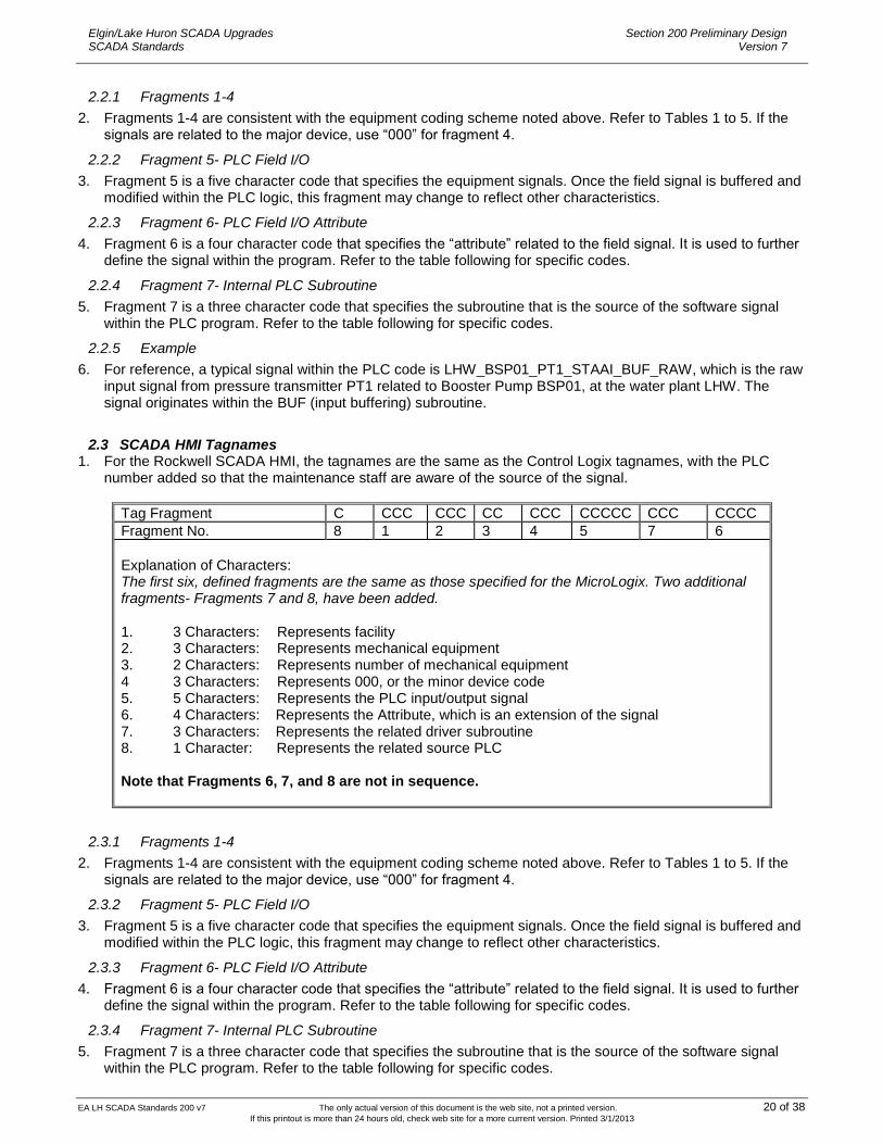
2.2.1 Fragments 1-4
2. Fragments 1-4 are consistent with the equipment coding scheme noted above. Refer to Tables 1 to 5. If the signals are related to the major device, use ―000‖ for fragment 4.
2.2.2 Fragment 5- PLC Field I/O
3. Fragment 5 is a five character code that specifies the equipment signals. Once the field signal is buffered and modified within the PLC logic, this fragment may change to reflect other characteristics.
2.2.3 Fragment 6- PLC Field I/O Attribute
4. Fragment 6 is a four character code that specifies the ―attribute‖ related to the field signal. It is used to further define the signal within the program. Refer to the table following for specific codes.
2.2.4 Fragment 7- Internal PLC Subroutine
5. Fragment 7 is a three character code that specifies the subroutine that is the source of the software signal within the PLC program. Refer to the table following for specific codes.
2.2.5 Example
6. For reference, a typical signal within the PLC code is LHW_BSP01_PT1_STAAI_BUF_RAW, which is the raw input signal from pressure transmitter PT1 related to Booster Pump BSP01, at the water plant LHW. The signal originates within the BUF (input buffering) subroutine.
2.3 SCADA HMI Tagnames 1. For the Rockwell SCADA HMI, the tagnames are the same as the Control Logix tagnames, with the PLC
number added so that the maintenance staff are aware of the source of the signal.
Tag Fragment C CCC CCC CC CCC CCCCC CCC CCCC
Fragment No. 8 1 2 3 4 5 7 6
Explanation of Characters: The first six, defined fragments are the same as those specified for the MicroLogix. Two additional fragments- Fragments 7 and 8, have been added.
1. 3 Characters: Represents facility 2. 3 Characters: Represents mechanical equipment 3. 2 Characters: Represents number of mechanical equipment 4 3 Characters: Represents 000, or the minor device code 5. 5 Characters: Represents the PLC input/output signal 6. 4 Characters: Represents the Attribute, which is an extension of the signal 7. 3 Characters: Represents the related driver subroutine 8. 1 Character: Represents the related source PLC Note that Fragments 6, 7, and 8 are not in sequence.
2.3.1 Fragments 1-4
2. Fragments 1-4 are consistent with the equipment coding scheme noted above. Refer to Tables 1 to 5. If the signals are related to the major device, use ―000‖ for fragment 4.
2.3.2 Fragment 5- PLC Field I/O
3. Fragment 5 is a five character code that specifies the equipment signals. Once the field signal is buffered and modified within the PLC logic, this fragment may change to reflect other characteristics.
2.3.3 Fragment 6- PLC Field I/O Attribute
4. Fragment 6 is a four character code that specifies the ―attribute‖ related to the field signal. It is used to further define the signal within the program. Refer to the table following for specific codes.
2.3.4 Fragment 7- Internal PLC Subroutine
5. Fragment 7 is a three character code that specifies the subroutine that is the source of the software signal within the PLC program. Refer to the table following for specific codes.
EA LH SCADA Standards 200 v7 The only actual version of this document is the web site, not a printed version. 21 of 38 If this printout is more than 24 hours old, check web site for a more current version. Printed 3/1/2013
Elgin/Lake Huron SCADA Upgrades SCADA Standards
Section 200 Preliminary Design Version 7
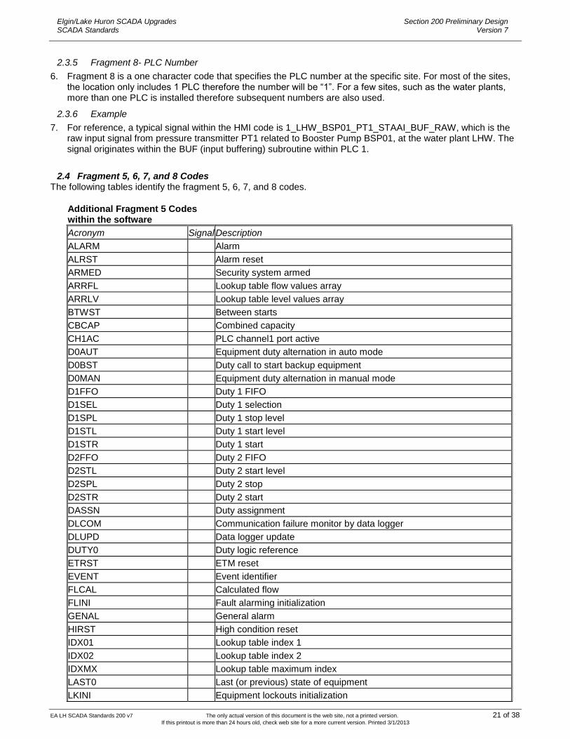
2.3.5 Fragment 8- PLC Number
6. Fragment 8 is a one character code that specifies the PLC number at the specific site. For most of the sites, the location only includes 1 PLC therefore the number will be ―1‖. For a few sites, such as the water plants, more than one PLC is installed therefore subsequent numbers are also used.
2.3.6 Example
7. For reference, a typical signal within the HMI code is 1_LHW_BSP01_PT1_STAAI_BUF_RAW, which is the raw input signal from pressure transmitter PT1 related to Booster Pump BSP01, at the water plant LHW. The signal originates within the BUF (input buffering) subroutine within PLC 1.
2.4 Fragment 5, 6, 7, and 8 Codes The following tables identify the fragment 5, 6, 7, and 8 codes.
Additional Fragment 5 Codes within the software
Acronym Signal Description
ALARM Alarm
ALRST Alarm reset
ARMED Security system armed
ARRFL Lookup table flow values array
ARRLV Lookup table level values array
BTWST Between starts
CBCAP Combined capacity
CH1AC PLC channel1 port active
D0AUT Equipment duty alternation in auto mode
D0BST Duty call to start backup equipment
D0MAN Equipment duty alternation in manual mode
D1FFO Duty 1 FIFO
D1SEL Duty 1 selection
D1SPL Duty 1 stop level
D1STL Duty 1 start level
D1STR Duty 1 start
D2FFO Duty 2 FIFO
D2STL Duty 2 start level
D2SPL Duty 2 stop
D2STR Duty 2 start
DASSN Duty assignment
DLCOM Communication failure monitor by data logger
DLUPD Data logger update
DUTY0 Duty logic reference
ETRST ETM reset
EVENT Event identifier
FLCAL Calculated flow
FLINI Fault alarming initialization
GENAL General alarm
HIRST High condition reset
IDX01 Lookup table index 1
IDX02 Lookup table index 2
IDXMX Lookup table maximum index
LAST0 Last (or previous) state of equipment
LKINI Equipment lockouts initialization
EA LH SCADA Standards 200 v7 The only actual version of this document is the web site, not a printed version. 22 of 38 If this printout is more than 24 hours old, check web site for a more current version. Printed 3/1/2013
Elgin/Lake Huron SCADA Upgrades SCADA Standards
Section 200 Preliminary Design Version 7
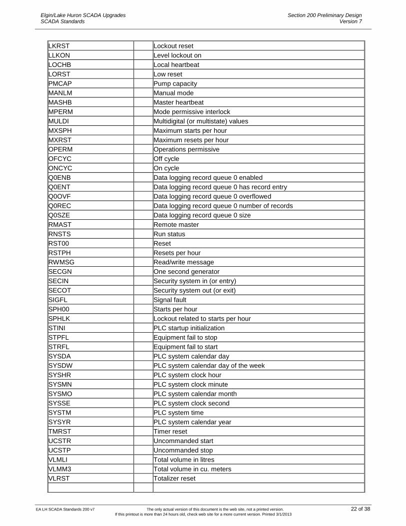
LKRST Lockout reset
LLKON Level lockout on
LOCHB Local heartbeat
LORST Low reset
PMCAP Pump capacity
MANLM Manual mode
MASHB Master heartbeat
MPERM Mode permissive interlock
MULDI Multidigital (or multistate) values
MXSPH Maximum starts per hour
MXRST Maximum resets per hour
OPERM Operations permissive
OFCYC Off cycle
ONCYC On cycle
Q0ENB Data logging record queue 0 enabled
Q0ENT Data logging record queue 0 has record entry
Q0OVF Data logging record queue 0 overflowed
Q0REC Data logging record queue 0 number of records
Q0SZE Data logging record queue 0 size
RMAST Remote master
RNSTS Run status
RST00 Reset
RSTPH Resets per hour
RWMSG Read/write message
SECGN One second generator
SECIN Security system in (or entry)
SECOT Security system out (or exit)
SIGFL Signal fault
SPH00 Starts per hour
SPHLK Lockout related to starts per hour
STINI PLC startup initialization
STPFL Equipment fail to stop
STRFL Equipment fail to start
SYSDA PLC system calendar day
SYSDW PLC system calendar day of the week
SYSHR PLC system clock hour
SYSMN PLC system clock minute
SYSMO PLC system calendar month
SYSSE PLC system clock second
SYSTM PLC system time
SYSYR PLC system calendar year
TMRST Timer reset
UCSTR Uncommanded start
UCSTP Uncommanded stop
VLMLI Total volume in litres
VLMM3 Total volume in cu. meters
VLRST Totalizer reset

EA LH SCADA Standards 200 v7 The only actual version of this document is the web site, not a printed version. 23 of 38 If this printout is more than 24 hours old, check web site for a more current version. Printed 3/1/2013
Elgin/Lake Huron SCADA Upgrades SCADA Standards
Section 200 Preliminary Design Version 7
Fragment 6 Codes within the software
Acronym Signal Description
ALM Alarm identifier
AUT Auto status identifier
BUF DI,AI Buffered field input values
CMD Command signals
CTR Counters
DAY Calendar day values
DBN Signal debounce on timer
DBF Signal debounce off timer
DLG Data logger reference
DWK Calendar day of the week values
EGU Values scaled to EGU
EMN Signal EGU zero scaling
EMX Signal EGU span scaling
ERR Error code identifier
ETM Elapse running time (or elapse time meter) values
FFO FIFO reference
FIL FILO reference
HBT Heartbeat
HMI HMI entered values
HOR Clock hour values
LUP Lookup table reference
MIN Clock minute values
MON Calendar month values
PLS Pulse signals
RAW DI, AI Raw field input values
REG Temporary holding register identifier
REQ Control request signals
RMN AI Minimum signal range values
RMX AI Maximum signal range values
RST Reset
SEC Clock seconds value
STS DI Signal status identifier
TMR Timer identifier
TOT Totalizer values
Fragment 7 Codes within the software
Acronym Signal Description
AIC Input conditioning subroutine (analog signals)
ALH Alarm handling subroutine
AST Analog statistics computation subroutine
DIC Input conditioning subroutine (digital signals)
DLG PLC data logging subroutine
DRV Device driver subroutine

EA LH SCADA Standards 200 v7 The only actual version of this document is the web site, not a printed version. 24 of 38 If this printout is more than 24 hours old, check web site for a more current version. Printed 3/1/2013
Elgin/Lake Huron SCADA Upgrades SCADA Standards
Section 200 Preliminary Design Version 7
DTY Equipment duty subroutine
IBF Input buffer subroutine
OBF Output buffer subroutine
SEC Facility security system subroutine
SEQ Auto control sequence subroutine
STH Startup and housekeeping subroutine
SYS PLC system parameters subroutine

EA LH SCADA Standards 200 v7 The only actual version of this document is the web site, not a printed version. 25 of 38 If this printout is more than 24 hours old, check web site for a more current version. Printed 3/1/2013
Elgin/Lake Huron SCADA Upgrades SCADA Standards
Section 200 Preliminary Design Version 7
2.5 Typical Device Tagnames The following provides the details on typical devices and I/O
Typical Minor Devices
Fragment 5
Motorized Open/Close Valve and Sluice Gates
REMOT DI Device L/R switch is in REMOTE position
OPENN DO Valve/Gate open command
CLOSE DO Valve/Gate close command
OPEND DI Valve/Gate is completely opened
CLOSD DI Valve/Gate is completely closed
FAULT DI Device Fault
Monitored Open/Close Valve and Sluice Gates
OPEND DI Valve/Gate is completely opened
CLOSD DI Valve/Gate is completely closed
Modulating Valve
REMOT DI Device L/R switch is in REMOTE position
SETPT AO Position/speed setpoint
FEDBK AI Position/speed feedback
OPEND DI Valve/Gate is completely opened
CLOSD DI Valve/Gate is completely closed
FAULT DI Device Fault
Modulating Open/Close Valve and Sluice Gates
REMOT DI Device L/R switch is in REMOTE position
OPENN DO Valve/Gate open command
CLOSE DO Valve/Gate close command
FEDBK AI Position/speed feedback
OPEND DI Valve/Gate is completely opened
STAAO DO Position speed indicator
CLOSD DI Valve/Gate is completely closed
FAULT DI Device Fault
Standard Transmitter (Pressure, Temperature, Flow, etc.)
STAAI AI Position/speed feedback and general instrument AI
FAULT DI Device fault general alarm (if available)
Miscellaneous Inputs
STADI DI General device status input high
STADO DO General Device status output to display value in local indicator

EA LH SCADA Standards 200 v7 The only actual version of this document is the web site, not a printed version. 26 of 38 If this printout is more than 24 hours old, check web site for a more current version. Printed 3/1/2013
Elgin/Lake Huron SCADA Upgrades SCADA Standards
Section 200 Preliminary Design Version 7
Typical Major Devices
Fragment 4 Fragment 5
FVNR Standard Starter
000 REMOT DI Device L/O/R switch is in REMOTE position
000 START DO Start device command
000 STOPP DO Stop Device Command
000 RUNNG DI Device is running
000 FAULT DI Device fault general alarm
Traveling Bar Screens
000 REMOT DI Device L/O/R switch is in REMOTE position
000 START DO Start device command
000 STOPP DO Stop Device Command
000 RUNNG DI Device is running
000 FAULT DI Device fault general alarm
Chemical Metering Pump
VFD REMOT DI Device L/O/R switch is in REMOTE position
VFD START DO Start/Stop device command
VFD RUNNG DI Device is running
VFD FAULT DI Device fault general alarm
VFD SETPT AO Speed or stroke setpoint
VFD FEDBK AI Speed or stroke feedback
Typical Pump VFD
000 REMOT DI Device L/O/R switch is in REMOTE position
VFD START DO Start/Stop device command
VFD RUNNG DI Device is running
VFD FAULT DI Device fault general alarm
VFD SETPT AO Speed or stroke setpoint
VFD FEDBK AI Speed or stroke feedback
000 FAULT DI Device fault general alarm
000 TRQHI DI Device high torque alarm
Screw conveyors and similar devices
000 REMOT DI Device L/O/R switch is in REMOTE position
000 START DO Start device command
000 RUNNG DI Device is running
000 FAULT DI Device fault general alarm
000 TRQHI DI Device high torque alarm
000 ESTOP DI Emergency stop/ pull cord activated

EA LH SCADA Standards 200 v7 The only actual version of this document is the web site, not a printed version. 27 of 38 If this printout is more than 24 hours old, check web site for a more current version. Printed 3/1/2013
Elgin/Lake Huron SCADA Upgrades SCADA Standards
Section 200 Preliminary Design Version 7
2.6 Control Wiring Labeling 1. The equipment labeling system is also used to complete the control wire labeling. Some of the fragments are
not used, to reduce the length of the wire labels.
Tag Fragment CCC CCC CC CCC CCC
Fragment No. 1 2 3 4 5
Explanation of Characters: 1. 3 Characters: not used 2. 3 Characters: Represents mechanical equipment or instrumentation 3. 2 Characters: Represents number of the major mechanical equipment 4. 3 Characters: Optional, represents the number of the minor piece of equipment, if applicable 5. 3 Characters: Represents the wire number
2. Fragments 2-4 are consistent with the equipment coding scheme noted above. Fragment 5 is a 3 digit wire
number, referenced on the control schematics.
2.7 Control Panel Labeling 1. All control panels must be labeled on the engineering drawings, and other design documents. In order to
accomplish this in an efficient manner, the following approach will be used. a. Large, major control panels will be identified using the CCP (centralized control panel) as fragment 2.
This is generally used when the panel has equipment and/or hand switches related to many devices. For example, CCP is used in the water filter area to designate the panels, which contain hand switches and indicators for all valves related to one water filter cell.
b. For the smaller, local hand switch station, or emergency pushbutton station, related typically to only one
major or minor device, the approach is to deviate slightly from the main equipment coding system. Utilize PANEL for fragment 5, as an acronym for control panel. For example, a local motorized valve hand switch station can be indicated as HLP01_DC1_PANEL on the drawings, and in the specifications where required. This is simply a method for uniquely identifying the panels for the tender documents, and maintenance staff, and is not related to SCADA I/O.
EA LH SCADA Standards 200 v7 The only actual version of this document is the web site, not a printed version. 28 of 38 If this printout is more than 24 hours old, check web site for a more current version. Printed 3/1/2013
Elgin/Lake Huron SCADA Upgrades SCADA Standards
Section 200 Preliminary Design Version 7
204 Process & Instrumentation Drawings (P&ID’s)
1. General This standard clearly presents Joint Board’s intent in developing P&ID’s. This standard is based on the Instrumentation Society of America (ISA) standard ISA-S5.1-1984, ―Instrumentation Symbols and Identification.‖ The material has been reformatted to be directly applicable to the water and wastewater industry. Although this section is based on ISA, it is not constrained by it. Comments are welcome for its enhancement.
1.1 Purpose of Standard This standard is intended to provide a consistent way of showing information. Consistent presentation will speed reading and improve understanding of the diagrams. Consistent preparation of the diagrams will enable the use of data base access to and from information on the diagrams. This standard will be included by reference into each design project and design or construction contract that prepares or modifies P&ID’s. Diagrams already prepared which are inconsistent with this standard will be converted to this standard whenever they are revised for other reasons. Existing diagrams, which are not compliant with this standard may also be converted to this standard if people using the diagrams can show benefit for the cost. The P&ID legend sheet and P&ID symbol sheets should be included in each instrumentation and control (I&C) drawing set developed for the Joint Boards.
1.2 ISA Reference Standard Duplication and conflict may exist between standards set by ISA and by other agencies or standards setting organizations such as Canadian Gas Association (CGA), National Fire Protection Association (NFPA), and International Standards Organization (ISO). The Joint Board has decided to produce P&ID’s that are consistent with ISA in order to have documentation readily understood by as wide an audience as practicable. The use of specialist symbols on P&ID’s would result in additional cost for training, documentation and workforce inflexibility. The use of symbols and nomenclature from standards other than ISA will be incorporated into this standard where no conflict exists. The CGA symbols were reviewed as part of preparing this standard. The CGA does not require the Joint Boards to prepare documentation using the symbols that the CGA itself uses in its standards and other publications. However, having documentation in a format familiar to boiler inspectors could expedite inspections and licensing of boilers. Therefore, the possibility of using CGA symbols instead of ISA symbols for boilers was explored. A number of conflicts occurred, particularly where the CGA was showing instrumentation and control information. The major problems came from misunderstanding of CGA instrumentation symbols by people applying ISA meanings to them. An alternative of showing both symbols sets, ISA and CGA, on the same drawing was examined. It would greatly increase drawing complexity and could also be misinterpreted as indicating two instruments when only one exists. Another alternative was explored of having two drawings, one where ISA symbols would be used if conflict occurs with CGA and another drawing showing only the CGA symbols. This method has several advantages. Two drawings are typically provided now. The ISA style drawing is part of the engineering design phase and the CGA drawing is part of the documentation provided by the boiler or compressor manufacturer. The result of this analysis is to prepare P&ID’s consistent with ISA and incorporate symbols from other standards organizations as needed.
1.3 Purpose of P&ID 1. P&ID’s convey process, instrument and control equipment information. A P&ID should enable anyone
reading it (and having a reasonable amount of plant knowledge) to understand the means of measurement and control of the process.
2. A P&ID is a specific schematic representation of the mechanical, electrical, instrumentation and control
aspects of a given process. The P&ID is developed from the process design engineer’s drawings and is expanded by the control engineer to include other instrumentation as needed.
3. The P&ID must be an accurate representation of the physical process or system and should show equipment
in the proper functional relation. A P&ID should include the following:

EA LH SCADA Standards 200 v7 The only actual version of this document is the web site, not a printed version. 29 of 38 If this printout is more than 24 hours old, check web site for a more current version. Printed 3/1/2013
Elgin/Lake Huron SCADA Upgrades SCADA Standards
Section 200 Preliminary Design Version 7
a. Process piping, tanks, structures, and equipment. b. Primary elements, transducers, and analyzers. c. Actuators and final control elements. d. Panels and controls. e. Input/output signals to digital controllers. f. Schematic representations of control signal interconnections.
4. The P&ID is the only document which shows both process and control information. As such, it can be a
valuable tool during design construction, and start-up. P&ID’s are used during design as a basis for: a. SCADA control strategy design. b. SCADA input/output point list development. c. Field instrument schedule development. d. Control panel design. e. Electrical interface definition. f. Mechanical and electrical equipment tagging. g. Overall design coordination.
5. During construction and start-up P&ID’s can be used for:
a. Shop drawing review of computer controls, panel and loop submittals. b. Electrical interface coordination. c. Graphic display development/approval. d. Process control operational checkout. e. Developing as-built and operation and maintenance manuals. f. Training.
1.4 Drawing Phases 1. The P&ID’s are developed in stages in order to add information at the appropriate time. The usefulness of
added details must be weighed against the expense of preparation and review effort. The P&ID development stages are shown in the following table.
Major Item Preliminary Design
Detailed Design Implementation
Piping, tanks, equipment and valves for process and auxiliary processes
Required Required Required
Sensors, transmitters, switches
Required Required Required
Actuator type with pneumatic and hydraulic instrumentation
Required Required Required
PLC I/O Points Indicated Not required Required Required
Panel - Face mounted instrumentation new/modified custom panels existing custom panels equipment package panels specialty package panels
Not required Not required Not required Not required
Required Required Not required Required
Required Required Required Required
Panel - Internal instrumentation new/modified custom panels existing custom panels equipment package panels specialty package panels
Not required Not required Not required Not required
Required Required Not required Required
Required Required Required Required
Representation Typical is okay No use of typicals No use of typicals
Control loops - hardwired Not required Required Required
Setpoints, limits Not required Not required* Required
* Required on instrument data sheets.

EA LH SCADA Standards 200 v7 The only actual version of this document is the web site, not a printed version. 30 of 38 If this printout is more than 24 hours old, check web site for a more current version. Printed 3/1/2013
Elgin/Lake Huron SCADA Upgrades SCADA Standards
Section 200 Preliminary Design Version 7
1.5 Scope of Drawings 1. A set of P&ID’s for a process or sub-process includes all aspects of the process or sub-process. That is, all of
the piping, equipment, instrumentation and controls in the process or sub-process must be included on the drawing set. For example, the set of P&ID’s for a pumping sub-process would include the main system, e.g. backwash water pumping and all auxiliary systems such as sample system, drainage system, service water, city (potable) water, instrument air, power distribution, gas monitoring, hydraulic and pneumatic systems, security, fire alarm and suppression, safety systems and heating, ventilation and air conditioning. a. The information includes all components of the process or sub-process. That is, the drawing set must
show : b. automated and non-automated systems, c. current project additions, deletions and modifications, d. existing conditions and future provisions if known.
2. The information shown on the P&ID’s includes major control logic of the process or sub-process control
strategies. That is, the drawing set must show : a. all hardwired interlocks, totalizers and signal converters, b. all standard controllers.
3. The P&ID’s must show all inputs and outputs of the Process Control System and the instruments and
equipment which provide the inputs and receive the outputs. 4. The P&ID’s do not need to show virtual points except as needed to clarify control logic. 5. The P&ID’s do not include equipment that is not associated with operation of the process or sub-process.
That is, the drawing set does not include such equipment as elevators, cranes, lights, vehicles, phones, fire extinguishers or computers.
1.6 Terminology 1. The following definitions are from ISA-S5.1-1984, ―Instrumentation Symbols and Identification.‖
a. Instrument - A device used directly or indirectly to measure or control a variable or both. The term includes control valves, relief valves, and electrical devices such as annunciators and push-buttons.
b. Instrumentation - A collection of instruments or their application for the purpose of observation, measurement, control, or any combination of these.
c. Primary Element - That part of a loop or of an instrument that first senses the values of a process variable. The primary element is also known as a sensor.
d. Final Control Element - That device that directly controls the value of the manipulated variable of a control loop.
e. Switch - A device (instrument) that connects, disconnects, selects, or transfers one or more circuits and is not designated as a controller, a relay, or a control valve.
f. Controller - A device having an output that varies in response to an input of a measured process variable to regulate a controlled variable in a specified manner. Typical instrument identifications are XC, XIC, and XFIC for controller, indicating controller and ration indicating controller respectively. X is the process or initiating variable. Controller types are auto/manual, computer/auto/manual or supervisory set point.
g. Control Station - A manual loading station that also provides switching between manual and automatic control modes of a control loop. It may be called an auto-manual station or an auto-selector station. The word computer may be substituted for auto when the control station is used with a computer. Typical instrument identification is HK or HIK. In rare cases, XK or CIK may be used where X is the process variable.
h. Manual Loading Station - A device having a manually adjustable output that is used to actuate one or more remote devices. It may be called a manual controller, manual station or remote manual loader. The station does not provide switching between manual and automatic control modes. Typical instrument identifications are HFK and HIXK for hand ratio control station and hand indicating unclassified control station. Manual loading stations are rarely, if ever, used in computer control systems.
i. Balloon - The circular symbol used to denote an instrument or instrument tagging. Synonym for bubble. j. P&ID - Process and Instrumentation Diagram. Do not substitute the words ―piping,‖ ―instrument‖ or
―drawing‖.
1.7 Process Layout 1. There are two general types of process layouts: those which show cast-in-place (concrete) or fabricated-in-
place (steel) tanks and those which show mechanical equipment or prefabricated process systems. An example of the former is a sludge treatment process, which includes (tanks), sludge pumps, and the

EA LH SCADA Standards 200 v7 The only actual version of this document is the web site, not a printed version. 31 of 38 If this printout is more than 24 hours old, check web site for a more current version. Printed 3/1/2013
Elgin/Lake Huron SCADA Upgrades SCADA Standards
Section 200 Preliminary Design Version 7
associated interconnecting piping and channels. Examples of the latter might include: centrifuges, +polymer batching system, instrument air supply systems, and chlorinators and ejectors. Each layout has certain graphic presentation characteristics, which are discussed below.
1.8 Tank System Layout 1. Always use plan views on this type of layout. 2. Although P&ID’s aren’t required to have a north-south orientation, in general, true north or plant north should
be toward the top of the drawing. In some cases, you may wish to rotate the process 90 degrees on the drawing so that it fits better. Rotate the process counter clockwise so that north is to the left.
3. Flow streams may enter and exit the drawing on all four sides. It is not necessary or desirable to maintain a
left to right or top to bottom flow direction. Flow streams enter and exit in relation to the process orientation and actual layout of the process.
4. Distinguish between channels and pipes and between prefabricated and cast-in-place tanks. Use double
lines spaced about 1/8‖ to indicate channel or cast-in-place tank walls. 5. Occasionally, you may have difficulty deciding whether to show a conduit as a pipe (single line) or a channel
(two pairs of lines to represent walls). Use the following guidelines: 6. Any conduit containing sluice gates, slide gates or flap gates either must be shown as a channel or must
contain a gate structure to hold the gate. 7. A conduit which is cast-in-place with a tank or set of tanks should normally be shown as a channel. Do not
sacrifice clarity to show the process schematically. 8. DO NOT typify process tanks or piping except through the use of process overview drawings.
1.9 Mechanical Equipment Layout 1. Plan or profile views may be used in this type of layout. In general, all piping to and from mechanical
equipment or piping within a prefabricated process system should be shown in plan view. Exceptions might include a water filter where a profile view would better show the feed pipes at various levels.
2. Flow direction should be from left to right and from top to bottom as much as possible. If a north-south
orientation is desired or is shown on other drawings, use that orientation.
1.10 Controls Layout
1.10.1 Control Levels
1. Use a layered approach to distinguish the various levels of control. Place field instrument and equipment balloons above or next to the devices. Locate field controls, motor controls, and area control panels above the field devices at separate levels. Locate computer input/output symbols and tags at the highest level.
2. The normal approach should use the area or unit process identification as recommended by ISA. An I/O point
sort by this identification can be used to establish the number of points in each area and the number of PLCs, RTU’s, DPCs, or RSCs based on assumed or specified sizing constraints.
1.10.2 Package Panels
1. Package panels are of two general types: equipment supplier furnished and specialty supplier furnished. Examples of equipment supplier furnished materials are: blower or centrifuge control panels, polymer or similar chemical mixing system control panels if furnished by the mixing system supplier, and pneumatic transport system controls. Examples of specialty panels are: motor controllers, variable speed drives, sump pump control systems, and HVAC controls.
2. For package panels, the supplier is responsible for the proper operation of the panel. The supplier must
perform the detailed engineering design to meet the functional requirements specified. The functional requirements include the desired operation, face of panel mounted equipment, panel layout, and interfaces with other control panels or computers. In many cases, the panel specifications are included within the equipment specifications and are written by others.

EA LH SCADA Standards 200 v7 The only actual version of this document is the web site, not a printed version. 32 of 38 If this printout is more than 24 hours old, check web site for a more current version. Printed 3/1/2013
Elgin/Lake Huron SCADA Upgrades SCADA Standards
Section 200 Preliminary Design Version 7
3. For example, a motor controller (MC) can be equipped with run lights, motor overload relays and lights, start/stop or on/off push-buttons and switches, local/remote switches and practically any other feature you desire including programmable controllers. Indicate these options on the P&ID’s using a combination of balloons for face mounted equipment and signal line labels for signals which are derived interior to the package panel and used elsewhere in the control loop.
4. Show the package panels as boxes with face of panel mounted instruments only. Do not show
interconnections, interlocks, interior signal function balloons, or signal function codes within the box. 5. All panels should be labeled in the upper left corner. If the package panel is shown on more than one
drawings, the word PARTIAL shall be included with the label.
1.10.3 Custom Panels
1. Custom panels are those panels which are designed by the engineer for fabrication by a panel shop or the control system supplier. The supplier of the equipment controlled by these panels usually has no contractual responsibility for the proper operation of the equipment.
2. Show these panels with both face and interior mounted instruments. Face mounted instruments have a
single, solid line across the instrument balloon. Interior mounted instruments have a single, dashed line across the instrument balloon. Show balloon interconnections and electrical interlocks.
3. Label panels in the same way as package panels.
1.10.4 Control Signals
1. Run SCADA output signal lines to local/remote selector switches to indicate that the switch selects between computer control and an alternate source of control. Show signals which are to be terminated within a panel by running the signal line up to the package panel border or through the custom panel. If the signal does not require termination in the panel, run the signal around the panel or use the break symbol. See Figure 2.
2. Label signal lines any time you think the function of the signal may be unclear. The label should be enclosed
in quotation marks.
1.10.5 Interlocks
1. Process interlocks are control connections wired between two separate equipment items. For example, a hard-wired control connection that causes an electro-hydraulic check valve to operate whenever a pump starts and stops is a process interlock. Show all process interlocks. Process interlock details are shown on electrical drawings. Drawing notes should describe the function of all interlocks and should refer to the electrical drawings and/or specifications for additional details.
2. Device protective interlock symbols should be shown if this is the policy started in the design guide for the
particular project. Protective interlocks are usually provided with the control device. For example, a pump may have protective interlocks which cause shutdown if sensors detect conditions such as excess vibration or high bearing temperature. This type of interlock is generally specified as a part of the device specification. It may or may not be shown on the electrical drawings. Always show these interlocks if the condition is to be displayed, alarmed or monitored.
1.10.6 Typifying
1. You can typify controls during preliminary design whenever you have typified equipment items. In addition, you can use typicals to reduce duplicated material. However, the typified controls must be functionally process related. Do not typify based on control interface only. For example, do not use one typical to show both return and waste sludge pump control.
2. Do not sacrifice clarity — when in doubt, do not typify even if additional drawings will be needed. 3. When typifying controls, the following rules apply:
a. Show all signals to and from balloons, control devices or primary elements. b. Include equipment tags whenever there are no other balloons which indicate the loop number. c. Show the loop numbers, panel designations, and equipment tags of all devices represented by the typical
box. d. Signal line arrowheads should point to the typical.

EA LH SCADA Standards 200 v7 The only actual version of this document is the web site, not a printed version. 33 of 38 If this printout is more than 24 hours old, check web site for a more current version. Printed 3/1/2013
Elgin/Lake Huron SCADA Upgrades SCADA Standards
Section 200 Preliminary Design Version 7
1.11 Overviews and Details 1. Drawings are attached as examples for reference.
1.11.1 Plant or System Overview
1. Prepare a plant or system overview drawing on all projects involving several unit processes, plants, or process areas. It will serve as a road map for the P&ID’s. The overview should be prepared after the P&ID’s are complete or near complete and should precede the P&ID’s in the drawing set.
2. The overview should show:
a. Each unit process, plant or process area by name and number. b. Flow streams between processes. c. P&ID or unit process overview drawing numbers.
1.11.2 Unit Process (Area) Overviews
1. Large or complex processes may require a process overview drawing. The overview may include a limited number of instruments and balloons. The overview should be oriented with north toward the upper part of the drawing if at all possible. Show process stream connections to other areas or unit processes. Subdivide the overview to correspond to the detailed P&ID’s. Process stream connections among P&ID’s within the unit process need not be shown.
1.11.3 Device Overviews
1. Large or complex devices may be shown as an overview symbol on a P&ID and then detailed on a separate drawing. The overview should identify the device, name the detail reference and show which panels contain instrumentation presented on the detail. If a panel is dedicated to the device it should only be shown on the device detail.
2. Some frequently occurring devices may also be shown as an overview symbol on a P&ID and detailed on another drawing as standard devices. The number of overview and detail layers should be minimized to reduce flipping between drawings. One drawing would be more convenient in the field, because of less paper handling and less chance of not bringing all the detail needed. Its usage should be restricted to where it is needed for clarity and consistency.
3. The choice and number of standard device designations needs to be managed on each project.
1.11.4 Redundant Information
1. Information should only be shown once. Do not repeat symbols for the same I/O point, instrument or piece of equipment.
1.12 Symbol and Legend Sheets 1. Refer to example drawing attached.
1.12.1 Primary Element Symbols
1. Identify the type of primary element early in the project. Mechanical layouts, instrument takeoffs, instrument application engineering, and quality control require definition of the type of primary element.
2. Minimize the use of unclassified primary element symbols. The most common use of the unclassified flow
symbol is for a flow switch. Use the unclassified level symbol when a pressure sensing instrument is used to indicate level, or for vendor packaged level instruments where the type is vendor dependent.
1.12.2 Miscellaneous Symbols
1. Any special, non-standard symbols can be added to this group. 2. The sight glass must be used in the vertical position as shown.
1.12.3 Actuator Symbols
1. Pneumatic and hydraulic actuators are equipped with solenoid actuated pilot valves. Show these valves. Show a pipe stub(s) for the air supply or hydraulic fluid supply and return.

EA LH SCADA Standards 200 v7 The only actual version of this document is the web site, not a printed version. 34 of 38 If this printout is more than 24 hours old, check web site for a more current version. Printed 3/1/2013
Elgin/Lake Huron SCADA Upgrades SCADA Standards
Section 200 Preliminary Design Version 7
2. Hydraulic operators may have an associated oil or water pump or may be connected to a hydraulic fluid system. Show the hydraulic fluid system, instrumentation and controls. Indicate the normal operating pressure range.
3. Always show the fail position designation at the lower right of the actuator symbol for the fail-safe action in
case of loss of air, hydraulic or electric power supply or control signal. Use abbreviations: FO (fail open), FC (fail close) or FL (fail lock).
1.12.4 Instrument and Function Symbols
1. Use separate, touching balloons for instruments that have more than one function such as controllers, control stations, valve actuators, multiple electrode level switches, sludge blanket detectors, and lighted switches.
2. Designate a panel mounted alarm light as:
LLL Level Light Low
3. For any light, the second letter must be an L. Placement of the L in the second position is needed to
distinguish between readouts and modifiers. For example:
LAL = level alarm low LL = level low (level light makes no sense) LLL = level light low LLLL = level light low low
4. Designate a panel mounted alarm annunciator point as:
LAL Level Alarm Low
5. Note that annunciators are distinct from alarm lights. An alarm light simply lights under alarm conditions. An
annunciator requires an acknowledgment to silence horns, stop the light from flashing or other actions. An annunciator may be a single light or may be part of an annunciator panel.
1.12.5 Flow Stream Identification
1. Identify all flow streams. Use the flow stream identifications shown on the P&ID Legend Sheet. If the project requires other flow stream identifications, you can alter the table shown. However, try to minimize the number of changes.
2. Except for plant influent and primary influent, label all flow streams based on the upstream process. For
example, use primary effluent not secondary influent.
1.12.6 Equipment Tagging
1. Use the rectangular equipment tag box if no balloon is used. If you use equipment tags which do not contain the loop number, you should use balloons to show the loop number.
2. Equipment tags are mandatory when typifying to show which device is associated with which loop.
1.12.7 Flow Stream and Instrument Line Symbols
1. Use three different line weights to distinguish flow streams. The main flow stream is the liquid train, the secondary flow streams include backwash water and process air, and other flow streams include chemicals, instrument air, drains, water, and steam.
2. Use dashed lines to indicate alternate flow streams. These streams included bypasses and streams, which
are not used for normal operations or for automatic backup.

EA LH SCADA Standards 200 v7 The only actual version of this document is the web site, not a printed version. 35 of 38 If this printout is more than 24 hours old, check web site for a more current version. Printed 3/1/2013
Elgin/Lake Huron SCADA Upgrades SCADA Standards
Section 200 Preliminary Design Version 7
3. Show all cast-in-place open channels and tanks in plan view and use double lines to indicate walls. Double lines help to distinguish between closed conduits (pipes) and tanks and open channels. Line weights and dashed lines are used as in the two previous items.
4. Use arrowheads to indicate direction of flow. Always use arrowheads where pipes connect and where pipes
enter tanks. 5. Do not use arrowheads upstream of primary elements, gates, pumps, valves, and other equipment. Use
enough for clarity and ease of tracing the flow stream. 6. When annotating flow streams or signal lines, enclose the annotation in quotes. 7. Label process equipment with a functional name, e.g. ―raw sludge pump‖ or ―treated water pump‖. Underline
the names of pumps, tanks and other process equipment. 8. All process flow streams and signal lines which are continued on another drawing shall be linked using the
labeled arrowheads. The arrowheads must be labeled with unique labels. The label is composed of the drawing number where the line is continued and an arrowhead number unique to that drawing. In complex cases, the arrowhead number should be made unique to all drawings in a sub-process. It is not necessary to add any other notes to indicate origin or destination.
9. Minimize the use of the continuation symbol, especially for flow streams. 10. Use the slashed arrowhead to indicate an origin or destination which is not a part of the project and which is
not continued on any other P&ID. Notes must be added to indicate origin or destination. Non-process lines such as potable and non-potable water used for flushing or pump seals, instrument-air lines and similar ancillary piping may be shown without slashed arrowheads.
1.12.8 Explanatory Notations
1. Hand switch and instrument designations should be placed at about the 1 o’clock position if at all possible. If confusion will result, place the designation at the 5 o’clock position.’
2. Spring return to center hand switches are similar to push-buttons. If a spring return switch is used, place a
note on the P&ID. If the project requires many spring return switches, supplement the explanatory notations. Use HMS to designate momentary switches.
3. Latching type push-buttons are not covered. If they are used, annotate them similar to spring return switches.
Use HS to designate maintained switches. 4. Hand switches and push-buttons may be equipped with lights. In most cases, the lights are connected to field
contacts such as valve position switches or motor running auxiliary relays. In some cases, the light may be used to indicate the switch position.
5. In some applications, you may wish to show both on and off status using two lights driven from one auxiliary
relay. 6. Show analysis instruments which are mounted in tees or which use pipe saddles or corporation stops as
tapped.
EA LH SCADA Standards 200 v7 The only actual version of this document is the web site, not a printed version. 36 of 38 If this printout is more than 24 hours old, check web site for a more current version. Printed 3/1/2013
Elgin/Lake Huron SCADA Upgrades SCADA Standards
Section 200 Preliminary Design Version 7
205 Process Narratives
1. General Requirements 1. The Process Narrative is a written description of key items and procedures of a specific process within a
treatment plant or pumping facility. The Narrative outlines the sequence of operations in Normal, Maintenance, and Emergency conditions, each in manual and automatic modes of control.
2. Text and descriptions are best given in concise sentences or paragraphs, or else in short, point-by-point
items. 3. Process Narratives can serve several different functions or purposes during the life of a project:
a. Background for planning and design of improvements b. Process control description for software development c. Basis for, or inclusion in, an Operations Manual d. Basis for Operations Practices Review e. Assist in development of Emergency Management System (ISO 14000)
4. Narratives start at the Project Planning stage, and evolve through the detailed design, implementation,
commissioning, and operation stages of a project. A pre-design narrative should include the equipment to be controlled and the methods (see philosophy) to be used. As the design progresses, the final process narrative details are within a ―Software Programming Requirements‖ document which should define exactly items such as equipment, I/O points, tag identification, equipment coding, methods of control and monitoring, normal operations, emergency operations, etc.
1.1 Content 1. Each distinct facility (water plant, pumping station, reservoir) within the Joint Board will have its own narrative.
All narratives will be of a consistent layout & format. Typically, there will be an overall facility process description, followed by a number of individual process and control description(s), dependant upon the complexity of the facility.
2. Each Process description is to define how each process is operated, and how the site-specific components of
the SCADA system operate and control the process under discussion. All process descriptions will be of a common format and content, as outlined further in this Standard.
1.2 Process Descriptions 1. A process description defines the physical operation of each process, either as an individual entity within a
treatment plant, or as a standalone description of an outstation. 2. Examples of Process Descriptions, which may be required within a Site Specific Process Narrative, include:
a. Water Plant b. Raw Water Pumping Station c. Preliminary Treatment d. Filtration e. Chemical System f. High Lift Pumping g. Standby Power h. Water Station/Reservoir Pumping (& Storage) Facilities i. Chemical Treatment j. Wastewater Lift Station Pumping Facilities
3. Each Process Description is to consist of two sections:
a. Operation Description b. Control Description
1.2.1 Operation Description
1. The operation description defines how the process system works, and how tasks interrelate to achieve the end result/product from the process being described.
EA LH SCADA Standards 200 v7 The only actual version of this document is the web site, not a printed version. 37 of 38 If this printout is more than 24 hours old, check web site for a more current version. Printed 3/1/2013
Elgin/Lake Huron SCADA Upgrades SCADA Standards
Section 200 Preliminary Design Version 7
2. Several of the items to follow will require information or procedures in response Normal, Maintenance and Emergency conditions.
Process Description The definition will include the process name, relationship to other processes, general components & physical parameters. Process capacities should also be included for Minimum, Average and Maximum Day conditions.
Process Objectives The objectives and general goals for this process are outlined here.
Objectives and goals are related to the efficiency, effectiveness, and end quality of the process itself.
Due to the interrelation between plant processes plus variance in operating conditions, it is recognized that there may need to be distinct objectives defined for any of normal, maintenance and emergency conditions. However, it may suffice to establish general objectives only for the normal operating conditions.
Process Control Strategy (ies) The strategy is a description of the process decisions to be taken to meet the treatment objectives outlined above. The strategy should include frequency of measurement of input variables, on which process adjustments are made.
As an extension of the Process Objectives, it will be necessary to establish specific Process Strategies for each of Normal, Maintenance and Emergency conditions.
Influent Sources A short outline of all the sources of influent into a process, including those flows re-circulated within a treatment facility.
Where multiple sources exist, provide the normal contribution of each source (as a percentage) to the overall process.
Effluent Destination(s) Information is presented as to where effluent and waste from the treatment process are normally directed. As an example, primary clarifier by-products include sludge and scum.
Where multiple destinations exist, provide the normal percentage distributed to each point.
Process Control Equipment/Devices In this section, each instrument or piece of equipment (pumps, valves,
transmitters) that can directly or indirectly control overall process influent or effluent must be identified. Identification should include name, equipment number (if possible), as well as performance ratings.
The use of each device/piece of equipment is to be outlined, including operation, individual control and performance objectives, and control methods.
Please see an example of an equipment / device identification summary at the end of this Standard.
Ancillary Processes Description of all processes associated with the main process, but not specifically involved with the influent, effluent, or actual treatment of the main process. An example would be Activated Sludge Pumping Systems.
These processes will have their own description in the same format.
Process Measurements/
EA LH SCADA Standards 200 v7 The only actual version of this document is the web site, not a printed version. 38 of 38 If this printout is more than 24 hours old, check web site for a more current version. Printed 3/1/2013
Elgin/Lake Huron SCADA Upgrades SCADA Standards
Section 200 Preliminary Design Version 7
Calculations The process description shall include, in tabular form, a summary of all end values and calculations which result from the monitoring and control of this process, and where the information is to be used.
This information will be used for process operation & evaluation, as well as report generation.
1.2.2 Control Description
1. The control system description outlines the general hardware and software requirements for operation specific to the process being outlined. The overall SCADA system description has been outlined earlier in this Standard.
Description This section outlines the operation of the process using the control system and control logic. General components are described including controllers, location of I/O and panels, etc.
Control Modes Description of the four possible control modes within the control system
(Local Control, SCADA Manual Control, Automatic, Expert System). Control Logic This section contains the descriptions for
Normal Operation Emergency Response Operation Hardware Interlocks Software Interlocks Associated Alarms for all equipment and devices within the Process.