ELECTRONICALLY COMMUTATED MOTORS Part 2: Constant …dirt load and closed dampers, registers, and...
12
CONSTANT-AIRFLOW, VARIABLE-SPEED (OEM) INDOOR BLOWER ECMs The constant-airflow (variable-speed) ECM was introduced in 1987 by GE (rebranded Genteq™ in 2009). It was the first and only indoor blower ECM until the introduction of the constant-torque ECM in 2006. The term “variable-speed motor” was coined in the late 1980s. By function it is a “constant-airflow motor.” Both of these terms define the type or style of ECM and how it is programmed to function. Variable-speed motors are built in 1 /3-, 1 /2-, 3 /4-, and 1-hp sizes, and only in direct-drive designs. These motors have gone through many generational improvements in their more than 20 years of existence, including advances in reliability and communication formats, as well as changes in their physical appearance. This chapter covers only the current-generation motors. The three main benefits of these motors over conventional induction (PSC) motors are: increased electrical efficiency more precise and unlimited airflow selection (the “variable-speed” feature) 1 ELECTRONICALLY COMMUTATED MOTORS Part 2: Constant-Airflow ECMs by Christopher Mohalley Genteq™ Certified Master ECM Trainer © 2010 by the Refrigeration Service Engineers Society, Des Plaines, IL Supplement to the Refrigeration Service Engineers Society. Service Application Manual SAM Chapter 650-004 Section 6A 16-pin ECM model Control module Motor module 4-pin ECM model Control module Motor module Figure 1. Construction of variable-speed ECMs COURTESY OF GENTEQ™
Transcript of ELECTRONICALLY COMMUTATED MOTORS Part 2: Constant …dirt load and closed dampers, registers, and...

CONSTANT-AIRFLOW, VARIABLE-SPEED (OEM)INDOOR BLOWER ECMs
The constant-airflow (variable-speed) ECM wasintroduced in 1987 by GE (rebranded Genteq™ in2009). It was the first and only indoor blower ECMuntil the introduction of the constant-torque ECM in2006. The term “variable-speed motor” was coined inthe late 1980s. By function it is a “constant-airflowmotor.” Both of these terms define the type or style of ECM and how it is programmed to function.
Variable-speed motors are built in 1⁄3-, 1⁄2-, 3⁄4-, and 1-hp sizes, and only in direct-drive designs.
These motors have gone through many generationalimprovements in their more than 20 years ofexistence, including advances in reliability andcommunication formats, as well as changes in theirphysical appearance. This chapter covers only thecurrent-generation motors.
The three main benefits of these motors overconventional induction (PSC) motors are:
� increased electrical efficiency
� more precise and unlimited airflow selection (the “variable-speed” feature)
1
ELECTRONICALLY COMMUTATED MOTORSPart 2: Constant-Airflow ECMs
by Christopher MohalleyGenteq™ Certified Master ECM Trainer
© 2010 by the Refrigeration Service Engineers Society, Des Plaines, ILSupplement to the Refrigeration Service Engineers Society.
Service Application ManualSAM Chapter 650-004
Section 6A
16-pin ECM modelControl module Motor module
4-pin ECM modelControl module Motor module
Figure 1. Construction of variable-speed ECMs
CO
URTESY
OF G
ENTEQ
™

� properly maintained airflow during changes insystem static pressure (the “constant-airflow”feature).
The ECMs shown in Figure 1 on the previous pageare actually built as two separate components. Thecontrol module (motor control), with its own shell orhousing, is attached to the back of the motor module(motor). The variable-speed motor control isprogrammed to provide constant airflow. This isaccomplished by converting the desired cfm to aspecific speed (rpm) and torque (current) delivered to the motor.
Each HVAC OEM (original equipment manufacturer)creates a special program unique to the model andsize unit in which the variable-speed ECM will beused. This program provides multiple airflow andcomfort options for each demand of the system inwhich the motor is installed, and any of the possibleconnected components.
To summarize: The variable-speed motor is operatedby two programs. The HVAC OEM program
determines the amount of airflow needed by demand,and the constant-airflow program makes sure that the selected airflow is maintained even if externalstatic pressure changes. The constant-airflowprogramming is unique to each OEM by model andsize of appliance. No two variable-speed motors areprogrammed alike.
OPERATION
The variable-speed ECM is a dual-voltage motor. The120-V ac or 240-V ac single-phase power is suppliedthrough the 5-pin connector to the motor at all times,even if there is no demand for airflow (see Figure 2).This power is what operates the internal electronicsand drives the motor. The low-voltage or serialcommunication that is sent to the motor from theOEM control board through the 16-pin or 4-pinconnector is a combination of the OEM programming,the installer’s selection of airflow and comfort settings,and the current demand of the HVAC system (heat,cool, fan, etc.). This is the information that the motorcontrol (microprocessor) requires to determine howmuch torque and speed the motor will need in order
to supply the proper airflow for each systemdemand.
During each demand, the motor control alsomonitors the actual speed in revolutions perminute (rpm) of the motor. There is only onecombination of torque and speed that willcreate the proper cfm demanded at a specifictotal ESP (external static pressure) of thesystem. If the speed/torque relationship isincorrect for the required airflow, the motorcontrol can increase or decrease the torque(current) to the motor. This, in turn, willincrease or decrease the speed of the motor to maintain airflow. By constantly monitoringthe actual speed of the motor, and maintainingthe torque/speed relationship programmed bythe HVAC OEM, the motor control is able tomaintain the airflow selection per demand ifthe total ESP changes.
Three very important points must beunderstood about this motor’s ability tomaintain a constant airflow:
2
CO
URT
ESY
OF
GEN
TEQ
™
4-pinconnection
5-pinconnection
16-pinconnection
5-pinconnection
Figure 2. Electrical connections

1. The motor requires more energy tomaintain airflow when the total ESP is higher than the HVAC OEMrecommendation, and the air noise of the system may be increased.
2. The motor requires less energy tomaintain airflow when the total ESP is equal to or less than the HVAC OEM recommendation, and the air noise of the system will be decreased.
3. The motor has a programmed limit ofoperation to protect itself from damage,due to the energy (current) it must use tomaintain airflow if the total ESP gets too high.Consult the HVAC OEM literature to find therecommended maximum total ESP. If the systemexceeds the HVAC OEM recommendation, airflowmay not be maintained—however, the motor willstill try to deliver as much air as possible, withoutcausing damage to itself.
APPLICATION AND BENEFITS
Variable-speed motors are typically found in two-stage, multi-stage, and modulating high-end furnaces(80+% and 90+% AFUE), air handlers, packagesystems, and geothermal systems.
Constant airflow is the ability of the variable-speedmotor to maintain its programmed and field-selectedairflow per demand, even when the total ESP ishigher than recommended and/or changes duringsystem operation. The total ESP (the resistance to the movement of air) is increased when ductwork isundersized, poorly constructed, and/or full of dirt ordebris. The total ESP can increase during systemoperation when dirt builds up on the air distributionsystem components (especially the filter), and whencustomers close or block grilles and registers.
The variable-speed motor is programmed to maintainairflow during all of these situations, within the limitsof the OEM programming and motor design. Bycontrast, torque (current) and airflow will decreasewhen the total ESP increases in PSC induction motorsystems (see Figure 3).
When set up correctly, the benefits of the variable-speed motor system include:
� energy savings
� improved outlet air temperature for each systemdemand
� improved humidity control
� improved system capacity
� reduced space temperature swings
� reduced air noise with soft start/stop and gradualchanges between airflow demands, delays, and/orprofiles
� reduced constant fan air noise with low cfmsettings, plus increased energy savings overnormal system operation
� reduced repairs associated with continuous low-airflow operation.
INSTALLATION AND SETUP
After the system is installed, the technician mustfollow the HVAC OEM’s instructions in selecting the proper airflow and comfort settings to match thecomponents and desired operation. These settings aretypically selected by using jumper pins, dip switches,and/or multi-pin plugs on the OEM control board
3
900
1000
1100
1200
1300
1400
1500
1600
1700
0.0 0.2 0.4 0.6 0.8 1.0
Air
flo
w, c
fm
Total ESP, in. w.g.
ECM PSC LO PSC MED PSC HI
Figure 3. Airflow vs. total ESP
CO
URTESY
OF G
ENTEQ
™

(see Figure 4). There are also some systems in whichmany of these selections can be adjusted at the userinterface. (In these systems, the user interfacereplaces the thermostat as the communication centerfor the system.) If these selections are not set at thetime of installation, there is a good chance that thesystem will not perform as expected and/or notproduce the designed capacity. In addition, thesystem may be prone to problems and/or prematureparts failures.
Figure 5 shows several examples of HVAC OEMairflow and comfort charts. The trim/adjust airflowchart allows the cooling airflow to be tweaked up ordown to increase the sensible or latent capability ofthe cooling system. The climate/delay profile chartsare designed to enhance the cooling cycle by climatefor either more dehumidification or OFF-cycle cooling.
Another comfort option that greatly enhancesdehumidification uses an external humidistat. Thehumidistat provides a demand to the HVAC systemthat is transferred to the motor to decrease the airflowduring the cooling cycle. This type of on-demanddehumidification typically requires a separatehumidistat or thermostat/humidistat combination,
and a setting on the control board in the OEM systemto initiate the feature.
It is recommended that the electrical connections onthe ECM be facing downward, or between the 4 and 8 o-clock positions, and a drip loop formed out of the wiring harness leaving the motor (see Figure 6).This prevents any moisture or water that may get into the motor area from running into the connectors,where it could cause damage to the control. In mostsystems, the OEM installs the motor in the correctposition and provides the drip loop. However, whenmulti-position systems are installed in a positionother than the manufactured position, the motor may need to be turned and the drip loop rearranged.
The total ESP of the installed system should bemeasured and compared to the OEM charts. If it isabove the maximum listed for that unit, improvementsshould be made to lower it. Any total ESP below themaximum is typically acceptable. However, systemefficiency, noise levels, and potential service issuesall will be improved when the total ESP is as close tothe OEM recommendation as possible. The OEM’sinstallation manuals provide guidelines that shouldbe followed per unit for best performance. Someimportant examples of the guidelines found in thesemanuals include filter-sizing charts, proper ductconnections, and unit cutouts.
The temperature rise in fossil-fuel systems shouldalways be measured and corrected if it is not withinthe OEM rating listed on the data plate of the givenunit.
Note: Water damage is one of the most frequentlyrecurring failures associated with electricalcomponents. Always construct and size thecondensate drains and traps according to OEMspecifications.
TROUBLESHOOTING
Before troubleshooting any HVAC system, it’s a good practice to become familiar with the systemcomponents and wiring diagram. Check for andfollow any on-board diagnostics (OEM system faultcodes). When you’re working on a variable-speed
4
Rotary switchfor delay time
Model plugs forheating selection
Rotary switch forcooling tonnage
4
3 5
2 X
X
4
3 5
2 X
X
Dip switches
3 4 5 6 7 821ON
Jumper pinsHEAT
A
B
C
D
COOL
A
B
C
D
DELAY
A
B
C
D
ADJUST
NORM
(+)
(–)
TEST
Figure 4. Control board options
CO
URT
ESY
OF
GEN
TEQ
™

system, you should also check the airflow, comfort,and delay settings. Typically you will need to consultthe HVAC OEM manuals for these settings. Themanufacturer’s literature can also provide valuablesequence-of-operation and troubleshooting help.
If the motor is running but the system is noisy,shutting down on its limits or safeties, or theevaporator coil is freezing, there is a good chancethat the problem is most likely external to the motorand the motor itself is good.
� Check the airflow settings using the HVAC OEMguide.
� Check the air distribution system components fordirt load and closed dampers, registers, andgrilles.
� Measure the total ESP and make the necessaryrepair(s) if it is above the maximum levelrecommended by the HVAC OEM. Aftermarketfilter sizing is a common issue.
Be aware, too, that thermostat (control) wiring is very important. HVAC equipment manufacturershave many different connection diagrams for theoperation of multi-stage furnaces and air handlerswith single-stage or multi-stage thermostats andoutdoor units. Often there are circuit board settingsthat correspond to the type of connection andoperation as installed. If the control wiring and
5
Figure 5. Typical HVAC OEM airflow and comfort charts
Back of motor control
Up
Wiring harnessformed into drip loop
Connectors facingdownward between4 and 8 o’clock positions
Figure 6. Drip loop
CO
URTESY
OF G
ENTEQ
™C
OU
RTESY O
F GEN
TEQ™

settings are not done properly, the system may runonly in one stage and/or be operating at the wrongairflow per stage.
If the motor is not running, the following checks willhelp you diagnose whether it is operational. Alwaysdisconnect the power to the HVAC system beforedisconnecting or reconnecting any connectors to themotor. There are two inputs needed to operate thistype of motor—a high-voltage constant power source,and the communication input that selects the airflowrequirement per demand. All of the connectors/plugsused with the motor are keyed for proper orientation.If connected improperly, the motor may not operateproperly and/or it may be damaged.
Step 1. Check the high-voltage input
First check the high-voltage input to the 5-pinconnector. Depending on the system, there should be120 V ac or 240 V ac at terminals 4 and 5 wheneverthere is power to the system, regardless of a demandcall (see Figure 7). If there is no high-voltage input,fix the problem in the system before proceeding. For120-V ac systems, make sure that the polarity of thepower connected to the motor is correct. If the high-voltage reading is within ±15% of the rated voltage,move on to the next step. If the reading is higher orlower than ±15% of the rated voltage, fix the voltageproblem first, then try to run the motor again. Alwayscheck for proper grounding and repair if needed.
6
3
4
5
2
1
Meter connected between terminals 4 and 5
Jumper connected between terminals 1and 2
Ground
Neutral
120-V ac L1
3
4
5
2
1
Ground
No jumper
120-V ac L2
120-V ac L1
Meter connected between terminals 4 and 5
Figure 7. Checking the high-voltage input
HVACsystemboard
24-V actransformer
R
C
Figure 8. Using the TECMate PRO
CO
URT
ESY
OF
GEN
TEQ
™C
OU
RTES
Y O
F G
ENTE
Q™
Note: As shown in Figure 7, 120-V ac motors musthave a jumper connected between terminals 1 and 2for proper operation. To prevent damage, 240-V acmotors should not have this jumper.
Step 2. Check the communication input
To check the communication to the motor on the 16-pin or 4-pin connector, you will need to have theHVAC system’s OEM manual showing pin-by-pinwhat voltage/communication should be present per demand. Voltage may be ac, dc, and/or serialcommunication.
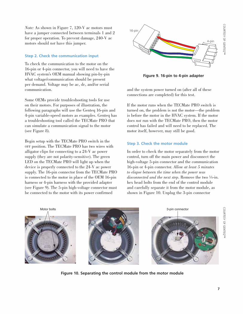
Some OEMs provide troubleshooting tools for use on their motors. For purposes of illustration, thefollowing paragraphs will use the Genteq 16-pin and4-pin variable-speed motors as examples. Genteq hasa troubleshooting tool called the TECMate PRO thatcan simulate a communication signal to the motor(see Figure 8).
Begin setup with the TECMate PRO switch in the OFF position. The TECMate PRO has two wires withalligator clips for connecting to a 24-V ac powersupply (they are not polarity-sensitive). The greenLED on the TECMate PRO will light up when thedevice is properly connected to the 24-V ac powersupply. The 16-pin connector from the TECMate PROis connected to the motor in place of the OEM 16-pinharness or 4-pin harness with the provided adapter(see Figure 9). The 5-pin high-voltage connector mustbe connected to the motor with its power confirmed
and the system power turned on (after all of theseconnections are completed) for this test.
If the motor runs when the TECMate PRO switch isturned on, the problem is not the motor—the problemis before the motor in the HVAC system. If the motordoes not run with the TECMate PRO, then the motorcontrol has failed and will need to be replaced. Themotor itself, however, may still be good.
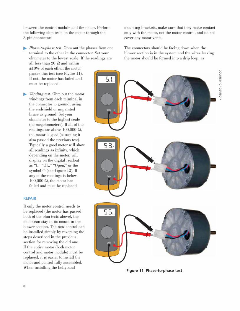
Step 3. Check the motor module
In order to check the motor separately from the motorcontrol, turn off the main power and disconnect thehigh-voltage 5-pin connector and the communication16-pin or 4-pin connector. Allow at least 5 minutes to elapse between the time when the power wasdisconnected and the next step. Remove the two 1⁄4-in.hex head bolts from the end of the control moduleand carefully separate it from the motor module, asshown in Figure 10. Unplug the 3-pin connector
7
CO
URTESY
OF G
ENTEQ
™
16-pin
4-pin
Figure 9. 16-pin to 4-pin adapter
Motor bolts 3-pin connector
Figure 10. Separating the control module from the motor module
CO
URTESY
OF G
ENTEQ
™
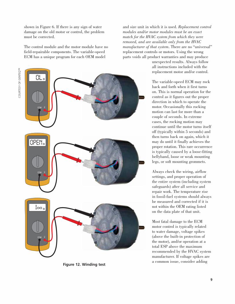
between the control module and the motor. Performthe following ohm tests on the motor through the 3-pin connector:
� Phase-to-phase test. Ohm out the phases from oneterminal to the other in the connector. Set yourohmmeter to the lowest scale. If the readings areall less than 20 Ω and within±10% of each other, the motorpasses this test (see Figure 11).If not, the motor has failed andmust be replaced.
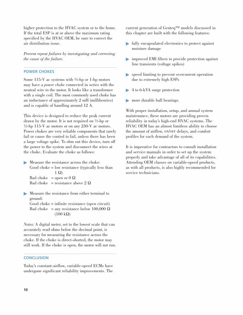
� Winding test. Ohm out the motorwindings from each terminal inthe connector to ground, usingthe endshield or unpaintedbrace as ground. Set yourohmmeter to the highest scale(no megohmmeters). If all of thereadings are above 100,000 Ω,the motor is good (assuming italso passed the previous test).Typically a good motor will showall readings as infinity, which,depending on the meter, willdisplay on the digital readout as “I,” “OL,” “Open,” or thesymbol ∞ (see Figure 12). If any of the readings is below100,000 Ω, the motor has failed and must be replaced.
REPAIR
If only the motor control needs tobe replaced (the motor has passedboth of the ohm tests above), themotor can stay in its mount in theblower section. The new control canbe installed simply by reversing thesteps described in the previoussection for removing the old one. If the entire motor (both motorcontrol and motor module) must bereplaced, it is easier to install themotor and control fully assembled.When installing the bellyband
mounting brackets, make sure that they make contactonly with the motor, not the motor control, and do notcover any motor vents.
The connectors should be facing down when theblower section is in the system and the wires leavingthe motor should be formed into a drip loop, as
8
Figure 11. Phase-to-phase test
CO
URTESY
OF G
ENTEQ
™
shown in Figure 6. If there is any sign of waterdamage on the old motor or control, the problem must be corrected.
The control module and the motor module have nofield-repairable components. The variable-speedECM has a unique program for each OEM model
and size unit in which it is used. Replacement controlmodules and/or motor modules must be an exactmatch for the HVAC system from which they wereremoved, and are available only from the HVACmanufacturer of that system. There are no “universal”replacement controls or motors. Using the wrongparts voids all product warranties and may produce
unexpected results. Always followall instructions included with thereplacement motor and/or control.
The variable-speed ECM may rockback and forth when it first turnson. This is normal operation for thecontrol as it figures out the properdirection in which to operate themotor. Occasionally this rockingmotion can last for more than acouple of seconds. In extremecases, the rocking motion maycontinue until the motor turns itselfoff (typically within 5 seconds) andthen turns back on again, which itmay do until it finally achieves theproper rotation. This rare occurrenceis typically caused by a loose-fittingbellyband, loose or weak mountinglegs, or soft mounting grommets.
Always check the wiring, airflowsettings, and proper operation of the entire system (including systemsafeguards) after all service andrepair work. The temperature risein fossil-fuel systems should alwaysbe measured and corrected if it isnot within the OEM rating listed on the data plate of that unit.
Most fatal damage to the ECMmotor control is typically related to water damage, voltage spikes(above the built-in protection of the motor), and/or operation at atotal ESP above the maximumrecommended by the HVAC systemmanufacturer. If voltage spikes area common issue, consider adding
9
Figure 12. Winding test
CO
URT
ESY
OF
GEN
TEQ
™
higher protection to the HVAC system or to the home.If the total ESP is at or above the maximum ratingspecified by the HVAC OEM, be sure to correct theair distribution issue.
Prevent repeat failures by investigating and correctingthe cause of the failure.
POWER CHOKES
Some 115-V ac systems with 3⁄4-hp or 1-hp motorsmay have a power choke connected in series with theneutral wire to the motor. It looks like a transformerwith a single coil. The most commonly used choke hasan inductance of approximately 2 mH (millihenries)and is capable of handling around 12 A.
This device is designed to reduce the peak currentdrawn by the motor. It is not required on 1⁄3-hp or 1⁄2-hp 115-V ac motors or on any 230-V ac motors.Power chokes are very reliable components that rarelyfail or cause the control to fail, unless there has beena large voltage spike. To ohm out this device, turn offthe power to the system and disconnect the wires atthe choke. Evaluate the choke as follows:
� Measure the resistance across the choke:Good choke = low resistance (typically less than
1 Ω)Bad choke = open or 0 ΩBad choke = resistance above 2 Ω
� Measure the resistance from either terminal toground:Good choke = infinite resistance (open circuit)Bad choke = any resistance below 100,000 Ω
(100 kΩ)
Notes: A digital meter, set to the lowest scale that canaccurately read ohms below the decimal point, isnecessary for measuring the resistance across thechoke. If the choke is direct-shorted, the motor maystill work. If the choke is open, the motor will not run.
CONCLUSION
Today’s constant-airflow, variable-speed ECMs haveundergone significant reliability improvements. The
current generation of Genteq™ models discussed inthis chapter are built with the following features:
� fully encapsulated electronics to protect againstmoisture damage
� improved EMI filters to provide protection againstline transients (voltage spikes)
� speed limiting to prevent overcurrent operationdue to extremely high ESPs
� 4 to 6-kVA surge protection
� more durable ball bearings.
With proper installation, setup, and annual systemmaintenance, these motors are providing provenreliability in today’s high-end HVAC systems. TheHVAC OEM has an almost limitless ability to choosethe amount of airflow, ON/OFF delays, and comfortprofiles for each demand of the system.
It is imperative for contractors to consult installationand service manuals in order to set up the systemproperly and take advantage of all of its capabilities.Attending OEM classes on variable-speed products,as with all products, is also highly recommended forservice technicians.
10


1666 Rand Road Des Plaines, IL 60016 800-297-5660 www.rses.org