Electronic SAR Imager MILESTONE #1 NEEDS ANALYSIS AND REQUIREMENTS SPECIFICATION TEAM E#11/M#27.
36
Electronic SAR Imager MILESTONE #1 NEEDS ANALYSIS AND REQUIREMENTS SPECIFICATION TEAM E#11/M#27
-
Upload
blaise-henry -
Category
Documents
-
view
221 -
download
0
Transcript of Electronic SAR Imager MILESTONE #1 NEEDS ANALYSIS AND REQUIREMENTS SPECIFICATION TEAM E#11/M#27.
Electronic SAR ImagerMILESTONE #1
NEEDS ANALYSIS AND REQUIREMENTS SPECIFICATION
TEAM E#11/M#27

2
Presentation Introduction Team Overview
Project Stakeholders
Code of Conduct
About Northrop Grumman
SAR Imager Overview
Necessary Components
Customer Wants & Needs
Requirements Specifications
Preliminary Test Plan
Preliminary Schedule, Budget, & Risk
JASMINE VANDERHORST - IE

3
Team Overview Project Manager & Webpage Developer
◦ Jasmine Vanderhorst – Industrial Engineer
Assistant Project Manager & Antenna Engineering
◦ Matthew Cammuse – Electrical Engineer
Assistant Project Manager ◦ Malcolm Harmon – Mechanical Engineer
Lead Engineer & Programmer◦ Patrick Delallana – Electrical & Computer Engineer
Co-Lead Engineer & Treasurer◦ Benjamin Mock – Industrial Engineer
Co-Lead Engineer & RF Engineer◦ Joshua Cushion – Electrical Engineer
Signal Processing Engineer & Document Control◦ Julia Kim – Electrical Engineer
Co-Lead Engineer◦ Mark Poindexter – Mechanical Engineer
JASMINE VANDERHORST - IE
4
Stakeholders Northrop Grumman
◦ Corporate Sponsor: Pete Stenger
Electrical and Computer Engineering ◦ Lead Coordinator: Dr. Michael Frank◦ Main Advisor: Dr. Simon Foo◦ Co-Main Advisor: Dr. Shonda Bernadin◦ Extra Reviewers: Dr. Bruce Harvey and Dr. Rajendra Arora
JASMINE VANDERHORST - IE

5
Stakeholders Mechanical Engineering
◦ External Coordinators: Dr. Nikhil Gupta and Dr. Scott Helzer◦ External Technical Advisor: Dr. Emmanuel Collins◦ Teaching Assistants: Ricardo Aleman and Samuel Botero
Industrial Engineering◦ External Coordinator: Dr. Okenwa Okoli◦ External Advisor: Dr. James Dobbs◦ Teaching Assistants: Emily Hammel and Margaret Scheiner
JASMINE VANDERHORST - IE
6
Code of Conduct Meeting Times
◦ Tuesdays – 7:00 pm Communication
◦ GroupMe App, Emails Document Transfer
◦ Dropbox and Blackboard Group File Exchange Conflict Resolutions
◦ Team Leader
JASMINE VANDERHORST - IE

7
Who is Northrop Grumman? Mission: To be at the forefront of technology and innovation, delivering super capability in tandem with maximized cost efficiencies.
Headquarter: West Falls Church, Virginia
Leading global security company
4th largest defense contractor in the world (2010)
JASMINE VANDERHORST - IE

8
Project OverviewASSISTANT PROJECT MANAGER: MALCOLM HARMON
MECHANICAL ENGINEER
Malcolm harmon - me 9
SAR Imager Overview Objective: Develop a fully-functional, low-cost detection electronic SAR imager◦ Low, but useful, image resolution◦ Commercial-off-the-shelf (COTS) components◦ Capital test equipment to get needed phenomenology information
Expected Output: Successful development of a low-cost prototype SAR imager

10
Antenna Aperture Project Approach Option 1
◦ Orthogonal Array◦ 1-D sparse antennas which would combine
images to get 2-D images
Project Approach Option 2◦ Sunflower Array◦ Sparse sunflower distribution across area
eliminating spatial ambiguities to generate image
MALCOLM HARMON - ME
11
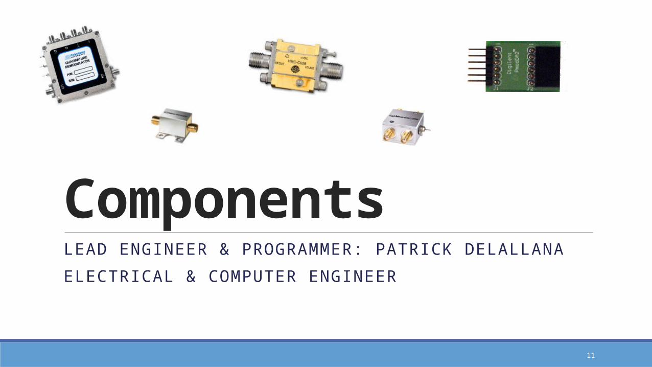
ComponentsLEAD ENGINEER & PROGRAMMER: PATRICK DELALLANA
ELECTRICAL & COMPUTER ENGINEER
12
Necessary Components Field Programmable Gate Array (FPGA)
Voltage Controlled Oscillator (VCO) Power Amplifier
Antenna◦ Horns
Low Noise Amplifier
Digital/Analog Converter
Analog/Digital Converter
Multiplier (x2)
PATRICK DELALLANA – ECE

13
Necessary Components Switches
◦ SPDT- Single Pole Double Throw◦ SPST – Single Pole Single Throw
Attenuator ◦ Reduces power of signal without changing waveform
Band Pass Filters◦ Smoothes out the wave for the IQ demodulator
IQ Demodulator◦ Determines the phase and the amplitude of the signal
PATRICK DELALLANA – ECE

14
IQ Demodulator: Q vs I graph
Has L port, which receives signal from VCO
Signal from antenna gets mixed with L port signal
(both have the same frequency)◦ IQ demodulator brings out I and Q portion ◦ Phase difference between antenna signal and L port signal

15
Customer Needs & WantsCO-LEAD ENGINEER: MARK POINDEXTER
MECHANICAL ENGINEER
MARK POINDEXTER – ME

16
Needs – Required Capabilities
CAP-001: Radar range of 20 feet
CAP-002: Operating frequency of X to Ku bands
CAP-003: Operation at safe frequencies
CAP-004: Detection of metal objects on test objects
CAP-005: Near real-time radar operation
CAP-006: Radar’s width of detection
CAP-007: Image generated from receiver data
MARK POINDEXTER – ME
17
Wants – Desired Capabilities
CAP-008: Radar detection of metal objects on multiple people
CAP-009: Detection of the area of body where metal object appears
CAP-010: System will focus on metal object as person moves
CAP-011: Real-time radar operation
MARK POINDEXTER – ME

18
Requirements SpecificationANTENNA ENGINEER & ASSISTANT PROJECT MANAGER:
MATTHEW CAMMUSE
ELECTRICAL ENGINEER
19
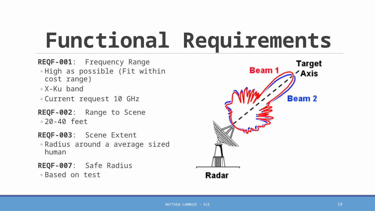
Functional Requirements REQF-001: Frequency Range
◦ High as possible (Fit within cost range)◦ X-Ku band◦ Current request 10 GHz
REQF-002: Range to Scene◦ 20-40 feet
REQF-003: Scene Extent◦ Radius around a average sized human
REQF-007: Safe Radius◦ Based on test
MATTHEW CAMMUSE – ECE
20
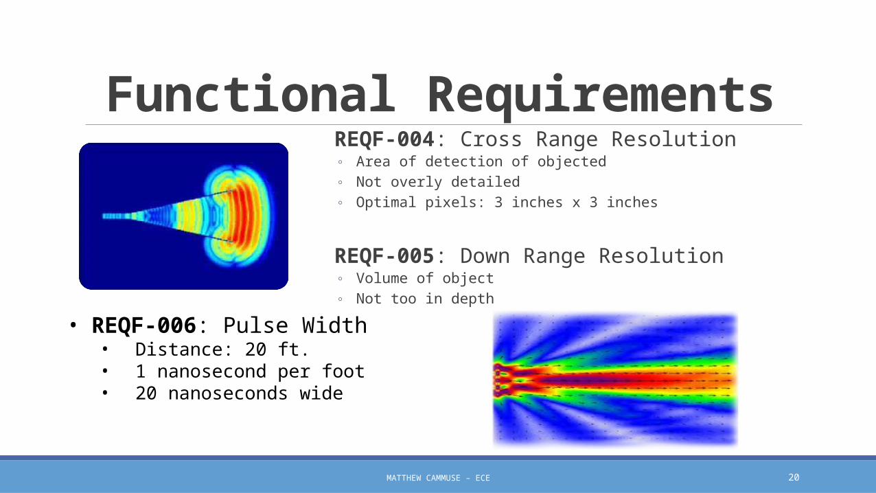
Functional Requirements REQF-004: Cross Range Resolution
◦ Area of detection of objected◦ Not overly detailed◦ Optimal pixels: 3 inches x 3 inches
REQF-005: Down Range Resolution◦ Volume of object◦ Not too in depth
• REQF-006: Pulse Width• Distance: 20 ft.• 1 nanosecond per foot• 20 nanoseconds wide
MATTHEW CAMMUSE – ECE
21
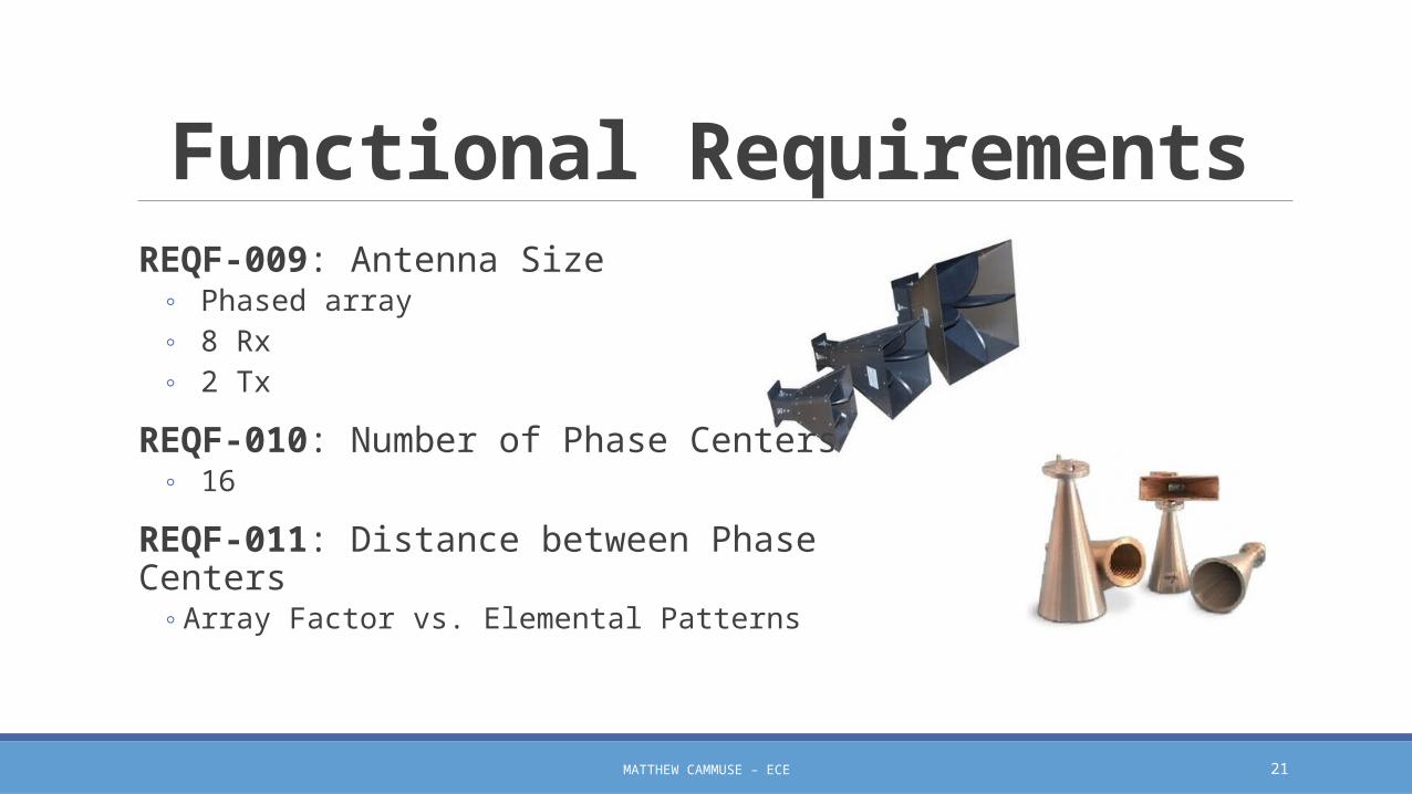
Functional RequirementsREQF-009: Antenna Size
◦ Phased array◦ 8 Rx◦ 2 Tx
REQF-010: Number of Phase Centers ◦ 16
REQF-011: Distance between Phase Centers◦ Array Factor vs. Elemental Patterns
MATTHEW CAMMUSE – ECE

22
Functional RequirementsREQF-008: Transmit Power
◦ Low Powered◦ Short Distance
REQF-012: Pulse Repetition Interval◦ Based on designated test◦ Start Slow
REQF-013: Receiver Noise Figure ◦ Expected Noise
REQF-014: Image Frame Rate◦ Image generator◦ Based on computer
MATTHEW CAMMUSE – ECE

23
Non-Functional Requirement
REQN-001: Radiation Safety◦ SAR imager functions to FCC regulations
REQN-002: Radar Transmitting Isolation◦ Radiation does not distort other electrical
systems
REQN-003: Cost Efficient◦ Low price◦ Dependent of frequency level
REQN-004: VHDL◦ Coding language for FPGA board
MATTHEW CAMMUSE – ECE

24
Requirement Constraints CONS-01: Antenna Amount
CONS-02: Antenna Arrangement
CONS-03: Testing & Radiation Safety
CONS-04: Project Timeline
MATTHEW CAMMUSE – ECE
25
Constraints & Capabilities Testing PlanSIGNAL PROCESSING ENGINEER & DOCUMENT CONTROL: JULIA KIM
ELECTRICAL ENGINEER
26
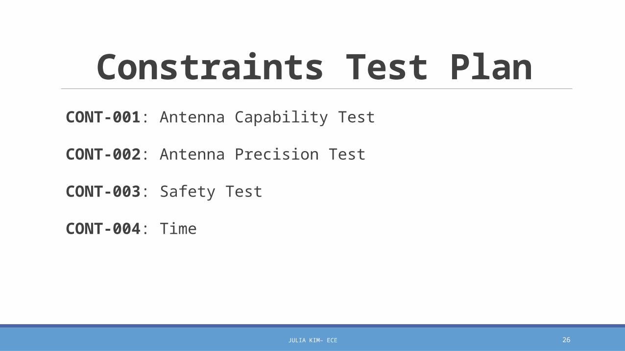
Constraints Test Plan CONT-001: Antenna Capability Test
CONT-002: Antenna Precision Test
CONT-003: Safety Test
CONT-004: Time
JULIA KIM– ECE

27
Capabilities Test Plan TESTC-0001: Physical Inspection Test
TESTC-0002: Power Test
TESTC-0003: RF Safe Test
TESTC-0004: Operating signal test
TESTC-0005: Receiver Signal Test 1.0
TESTC-0006: Receiver Signal Test 2.0
TESTC-0007: Computer Image Test
JULIA KIM– ECE
28
Requirements Testing PlanCO-LEAD & RF ENGINEER: JOSHUA CUSHION
ELECTRICAL ENGINEER
JOSHUA CUSHION – ECE

29
Requirements Test Plan TESTFF-001: Frequency Range
TESTFF-002: Range of Scene to be Imaged
TESTFF-003: Scene Extent
TESTFF-004: Cross Range Resolution
TESTFF-005: Down Range Resolution
JOSHUA CUSHION – ECE

30
Requirements Test Plan TESTFF-006: Pulse Width
TESTFF-007: Safe Radius
TESTFF-008: Transmit Power
TESTFF-009: Verify Proper Antenna Size
TESTFF-010: Number of Phase Centers
JOSHUA CUSHION – ECE

31
Requirements Test Plan TESTFF-011: Distance between Phase Centers
TESTFF-012: Pulse Repetition Interval
TESTFF-013: Receiver Noise Figure
TESTFF-014: Image Frame Rate
JOSHUA CUSHION – ECE

32
Preliminary Budget, Schedule, & RisksCO-LEAD ENGINEER & TREASURER: BENJAMIN MOCK
INDUSTRIAL ENGINEER
BENJAMIN MOCK - IE

33
Project Funding Funds are being provided from Northrop Grumman through the FAMU-Foundation
Approximate Budget $50,000
Purchasing Capability: P-Card
◦ For large purchases contact Donna Butka (FAMU/FSU COE – ECE)
FAMU Access & Cost Management
◦ Jasmine Vanderhorst
BENJAMIN MOCK - IE

34
Preliminary Project Schedule
BENJAMIN MOCK - IE
Microsoft Project Document

35
Preliminary Risk Assessment Meeting Facilities & Reservations
Testing Facility Acquisition
Equipment and Parts Procurement
Design Assessment/Scope Adjustment
Documentation Control
Radiation Absorption◦ OSHA 1910.97(a)(2)(i) 10 mW/cm2
◦ OSHA 1910.97(a)(3)(i) Appropriate Warning Sign
BENJAMIN MOCK - IE

36
References Stenger, Pete, “Electronic SAR Imager” – Posted on Blackboard
Stenger, Pete, “Radar Imager Performance Characteristics” – Posted on Blackboard