
Electromagnetic Pulse Forming of Carbon Steel Sheet...
12
Electromagnetic Pulse Forming of Carbon Steel Sheet Metal R. Andersson, M. Syk Swedish Tool & Die Technology, Luleå, Sweden Abstract Electromagnetic pulse forming is a promising direct method for a high speed sheet metal forming of materials with high conductivity, like Al- and Cu-alloys. For metallic sheet with low conductivity, like carbon steel sheets, the frequency of the current through the forming coil must increase to create the same forming properties as for materials with high conductivity. Usually this frequency is not easy to change in an existing electromagnetic pulse system without exchanging of the capacitors. Anyway, this project have analysed the formability of two high strength steel sheet material, a carbon steel DP60 and a austenitic stainless steels, with and without a copper driver. The experiments were made on commercial electromagnetic pulse system from Poynting with a predefined current frequency through the forming coil. The geometries that were used for the electromagnetic pulse forming analysis were a cone, rectangular parts, and spherical dome. All physical parts were 3D digitised and the deviation were analysed against nominal reference objects. The spherical dome experiment was used to analyse the increase in formability of the high strength steel sheets compared with conventional stamping in an Erichsén sheet metal testing machine. Keywords Steel sheet formability, Geometrical deviation, 3D analysis 1 Introduction This project deals with high velocity deformation of steel metallic materials using electromagnetic pulse as driving mechanism for the forming force. Electromagnetic pulse forming is a high velocity process where a coil creates a magnetic field which repels the sheet material and pushes it down to a die. The most important parameters that influence the process are: energy level, induced current, electrical conductivity and the mechanical properties of the sheet material and the geometry. This means to get a successful Magpulse Technologies 1
-
Upload
truongtruc -
Category
Documents
-
view
227 -
download
3
Transcript of Electromagnetic Pulse Forming of Carbon Steel Sheet...

Electromagnetic Pulse Forming of Carbon Steel
Sheet Metal
R. Andersson, M. Syk
Swedish Tool & Die Technology, Luleå, Sweden
Abstract
Electromagnetic pulse forming is a promising direct method for a high speed sheet metal forming of materials with high conductivity, like Al- and Cu-alloys. For metallic sheet with low conductivity, like carbon steel sheets, the frequency of the current through the forming coil must increase to create the same forming properties as for materials with high conductivity. Usually this frequency is not easy to change in an existing electromagnetic pulse system without exchanging of the capacitors.
Anyway, this project have analysed the formability of two high strength steel sheet material, a carbon steel DP60 and a austenitic stainless steels, with and without a copper driver. The experiments were made on commercial electromagnetic pulse system from Poynting with a predefined current frequency through the forming coil.
The geometries that were used for the electromagnetic pulse forming analysis were a cone, rectangular parts, and spherical dome. All physical parts were 3D digitised and the deviation were analysed against nominal reference objects.
The spherical dome experiment was used to analyse the increase in formability of the high strength steel sheets compared with conventional stamping in an Erichsén sheet metal testing machine.
Keywords
Steel sheet formability, Geometrical deviation, 3D analysis
1 Introduction
This project deals with high velocity deformation of steel metallic materials using electromagnetic pulse as driving mechanism for the forming force. Electromagnetic pulse forming is a high velocity process where a coil creates a magnetic field which repels the sheet material and pushes it down to a die. The most important parameters that influence the process are: energy level, induced current, electrical conductivity and the mechanical properties of the sheet material and the geometry. This means to get a successful
Magpulse Technologies
1

3rd International Conference on High Speed Forming – 2008
electromagnetic pulse forming process is that the current will flow as close as possible to the surface of the material to be deformed. The higher the electrical conductivity in the sheet material the less is the induced current thickness. This is easily described by the magnetic skin depth as a function of frequency, which is mathematically described by
f
ρπ μ
Δ = (1)
where f is the frequency, ρ is the resistivity of the sheet material and μ is the absolute magnetic permeability of the metallic sheet [1]. To achieve a good forming process the magnetic skin depth should not become larger then the sheet metal thickness. Equation 1 shows clearly that the frequency is a very important parameter to create a successful electromagnetic pulse process. The frequency of an electromagnetic pulse system comes mainly from the type and the amount of capacitors. Equation 1 shows also that different type of metallic sheet materials get different values of the magnetic skin depth at same frequency due to differences in resistivity. Some metallic materials resistivity is found in table 1 below.
Conductivity
Material [106 Siemens/m] [% IACS]
Resistivity [10-9 ohm-m]
Silver (pure) 62,87 108,40 15,91 Copper (pure) 60,09 103,60 16,64 Gold (pure) 40,60 70,00 24,63 Aluminium (99.99%) 37,67 64,94 26,55 Aluminium 6062-T6 27,32 44,70-49,50 36,61 Aluminium 6062-T4 25,38 43,50-44,00 39,41 Magnesium (pure) 22,39 38,60 44,67 Iron (Casted 99.9%) 9,048 15,60 110,5 Magnesium (Casted) 8,70 15,00 114,9 Steel (Casted) 6,21 10,70 161,1 Steel (High-alloyed) 1,68 2,90 594,5 Stainless Steel 316 1,33 2,30 749,6 Titanium (6AL-4V) 0,58 1,00 1724
Table 1: Conductivity and resistivity for some metallic materials [2]
Table 1 shows together with equation 1 that for specific system with prescribed frequency the magnetic skin depth will be much higher for materials with high resistivity. This means that materials like steel and stainless steels become more difficult to achieve with low frequency system. One way to overcome this problem is to use a foil of low resistive material on top of the steel sheet material and that foil will act as a driver to push the steel sheet into the die cavity.
This paper will investigate the electromagnetic forming process of steel metallic sheets with and without a driver material. The objective will be to analyse the difference of
Magpulse Technologies
2

3rd International Conference on High Speed Forming – 2008
the formability with or without driver, the deviation and springback from the nominal geometry and also the increase in formability.
2 Material and Experiments
2.1 Sheet Metallic Materials
The materials used in this study are one austenitic stainless steel and one high-strength carbon steel, both in the as-received condition. The thickness and strength levels are tabulated in table 2.
Grade Thickness (mm) Rp02 (MPa) UTS (MPa)
Stainless Steel EN1.4401 0.25 319 635 Carbon Steel DP600 0.7 432 640
Table 2: The sheet materials in this study
a) b)
c) d)
Figure 1: a) shows the coil b) the die with a specific pattern c) the die with rectangular inserts and d) the die with oval and round inserts.
2.2 Coil and Dies
The electromagnetic coil that was used for the experiments were designed in collaboration with the company Poynting [3], Dortmund, Germany. The design was made so a homogenous pressure should occur on the sheet metal during the electromagnetic pulse forming process. Three dies were used in this study. Two of the dies had exchangeable inserts, one with inserts for conical parts and hemispherical domes and the other for
Magpulse Technologies
3

3rd International Conference on High Speed Forming – 2008
rectangular parts. The third die was designed to analyse a forming process to create a surface pattern of a sheet metal similar to what can be found on heat-exchanger or bipolar plates. The electromagnetic coil and dies is shown in figure 1.
2.3 Electromagnetic Pulse Experiments
All electromagnetic pulse forming experiments were done at a Magnaform Maxwell 60kJ system located at Poynting. The technical data of the system is found in table 3.
Characteristics Max charging energy E 60 kJ Max Charging voltage U 8.3 kV Capacitance C 1742 µF Max permitted current 1800 kA Short circuit frequency 25-29 kHz
Table 3: shows the characteristics of the electromagnetic pulse system Magnaform Maxwell 60kJ that was used in this study.
To improve the efficiency of the electromagnetic pulse forming process for sheet metal material with low conductivity is to use a high conductivity foil between coil and sheet metal. This foil will then act as pressure device on the sheet metal during the electromagnetic pulse process. This trick improves the formability process of low conductivity materials.
The first experiments was to make a comparison study of the difference of forming process of the carbon steel DP600 with and without a copper foil as a driver. The energy level and current-trace curves for this experiment are found in appendix 1.
The second experiment was to compare the improvement of formability for DP600 in equivalent biaxial tension between electromagnetic pulse process and conventional Erichsen test. The energy level and current-trace curves for this experiment are found in appendix 1.
The third experiment was to analyse the geometrical deviation and springback after the electromagnetic forming process of the stainless steel grade with copper foil as a driver. The energy level and current-trace curves for this experiment are found in appendix 1.
2.4 Erichsen Sheet Metal Forming Test
Quadratic samples of 250x250 mm width were stretched with a loading path of equivalent biaxial tension over a hemispherical punch with a diameter of 50.8mm until fracture occur in an Erichsen 40 tonne hydraulic press [4]. For the subsequent strain analysis all sheet metal specimens were electrochemical etched with a square pattern of 2x2 mm.
Magpulse Technologies
4

3rd International Conference on High Speed Forming – 2008
3 Analysis and Results
3.1 Analyse of Experiment Nr 1
The first experiments were to make a comparison study of the difference of forming process of the carbon steel DP600 with and without a copper foil as a driver. The foil had a thickness of 0.6 mm. After the electromagnetic forming processes of the two deformed blanks they become digitised by 3D scanning with an ATOS III system from GOM [6]. Subsequently a best fit algorithm has been used to compare the 3D deviation between the deformed sheets and 2D cuts have been used to make a detailed comparison. The cut position and the comparison are shown in figure 2-5.
Figure 3-5 show the major impact a copper driver has on the formability of high strength steel sheets with the current-trace curve that is described in appendix a1. The conclusion is: to improve the sheet metal forming performance without using a copper foil as a driver a high frequency electromagnetic pulse system must be used. This conclusion can also be drawn from the description of equation 1.
Figure 2 shows the three 2D cuts for the comparison study.
Magpulse Technologies
5

3rd International Conference on High Speed Forming – 2008
Figure 3 shows the deviation between the shape of DP600 with and without copper driver at cross-cut 1.
Figure 4 shows the deviation between the shape of DP600 with and without copper driver at cross-cut 2.
Magpulse Technologies
6
3rd International Conference on High Speed Forming – 2008
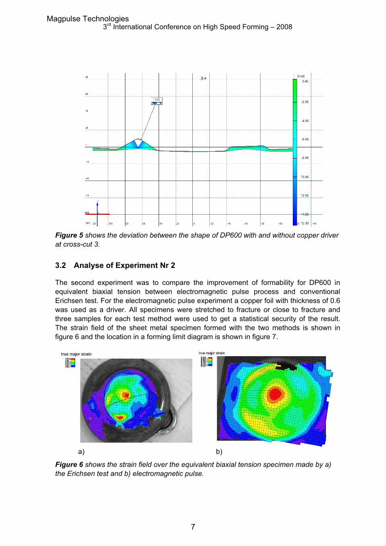
Figure 5 shows the deviation between the shape of DP600 with and without copper driver at cross-cut 3.
3.2 Analyse of Experiment Nr 2
The second experiment was to compare the improvement of formability for DP600 in equivalent biaxial tension between electromagnetic pulse process and conventional Erichsen test. For the electromagnetic pulse experiment a copper foil with thickness of 0.6 was used as a driver. All specimens were stretched to fracture or close to fracture and three samples for each test method were used to get a statistical security of the result. The strain field of the sheet metal specimen formed with the two methods is shown in figure 6 and the location in a forming limit diagram is shown in figure 7.
a) b)
Figure 6 shows the strain field over the equivalent biaxial tension specimen made by a) the Erichsen test and b) electromagnetic pulse.
Magpulse Technologies
7

3rd International Conference on High Speed Forming – 2008
Figure 7 shows the strain region at fracture either through conventional Erichsen sheet metal testing or through electromagnetic pulse forming.
Figure 6 and 7 show that we can get an increase in formability with more then 50% of high strength steel sheets if a copper driver is used compared to standard formability tests with a hydraulic press.
3.3 Analyse of Experiment Nr 3
The third experiment was to analyse the geometrical deviation and springback after the electromagnetic forming process of a sheet metal of stainless steel with thickness of 0.25 mm together with a copper foil with thickness of 0.1 mm, which acts as a driver. The final formed part were digitised by 3D scanning with an ATOS III system from GOM [6] and the comparison were made against the nominal CAD data. The result is shown in figure 8. Figure 8 shows that the springback and geometrical deviation is very low. One reason for this minimal geometrical deviation after electromagnetic pulse forming is that the sheet metal hit the die surface with really high speed and this causes a plastic deformation through the sheet thickness which minimise the tendency for springback.
There has also been experimental test with thicker stainless steel sheets together with thicker copper foil as driver and the tendency is similar i.e. minimum springback tendency. Increase in thickness demands of course higher energy levels from the electromagnetic pulse system.
Magpulse Technologies
8

3rd International Conference on High Speed Forming – 2008
Figure 8 shows the deviation of the electromagnetic pulse formed part and the nominal geometry.
4 Conclusion
The major conclusion from this study are that electromagnetic pulse forming of steel sheets without using any high conductive material that acting as a pressure device must be done on a high-frequency electromagnetic pulse system. The reason for this can be found in equation 1 and table 1, which shows if the resistivity of the sheet material is increasing then an increase in frequency is needed to get an efficient process.
If it should be possible to develop and manufacture a electromagnetic pulse system that have same performance as for low resistivity material i.e. increased system frequency then we see from the experiments 2 and 3 in this study that we could achieve both an increase in formability of high strength steel sheet materials as well as a decrease in springback.
Magpulse Technologies
9

3rd International Conference on High Speed Forming – 2008
References
[1] Hayt W. H.: Engineering Electromagnetics Seventh Edition,(2006), McGraw Hill, New York ISBN 0-07-310463-9
[2] Syk, M: Electromagnetic Pulse Processes – A literature survey (2004), Svensk Verktygsteknik
[3] www.poynting.de (2008-01-25) [4] www.erichsen.de (2008-01-25) [5] www.autogrid.de (2008-01-25) [6] www.gom.com (2008-01-25)
Magpulse Technologies
10

3rd International Conference on High Speed Forming – 2008
Appendix A Energy Levels and Current Trace Curves
A.1 Experiment Nr 1
The energy level was 14 kJ and the current trace curve is shown in figure 9.
-100
-50
0
50
100
150
200
0,00000 0,00010 0,00020 0,00030 0,00040 0,00050 0,00060
Time (s)
Cu
rre
nt
(kA
) With copper foil
Without copper foil
Figure 9 shows the current-trace curve for experiment 1.
A.2 Experiment Nr 2
The energy level was 14 kJ and the current trace curve is shown in figure 10.
-100
-50
0
50
100
150
200
0,00000 0,00010 0,00020 0,00030 0,00040 0,00050 0,00060
Time (s)
Cu
rre
nt
(kA
)
Experiment 2
Figure 10 shows the current – trace curve for experiment 2
Magpulse Technologies
11

3rd International Conference on High Speed Forming – 2008
A.3 Experiment Nr 3
The energy level was 3 kJ and the current trace curve is shown in figure 11.
-40,00
-20,00
0,00
20,00
40,00
60,00
80,00
100,00
0,00000 0,00010 0,00020 0,00030 0,00040 0,00050 0,00060
Time (s)
Cu
rren
t (k
A) Experiment 3
Figure 11 shows the current – trace curve for experiment 3
Magpulse Technologies
12