
Electrodynamic Tether Propulsion and Power Generation at Jupiter … · NASA / TP--1998 -208475...
31
NASA / TP--1998 -208475 Electrodynamic Tether Propulsion and Power Generation at Jupiter D.L. Gallagher and L. Johnson Marshall Space Flight Center, Marshall Space Flight Center, Alabama J. Moore SRS Technologies, Huntsville, Alabama F. Bagenal University of Colorado, Boulder, Colorado National Aeronautics and Space Administration Marshall Space Flight Center June 1998 https://ntrs.nasa.gov/search.jsp?R=19980203952 2018-07-21T03:43:33+00:00Z
Transcript of Electrodynamic Tether Propulsion and Power Generation at Jupiter … · NASA / TP--1998 -208475...

NASA / TP--1998 -208475
Electrodynamic Tether Propulsion
and Power Generation at JupiterD.L. Gallagher and L. Johnson
Marshall Space Flight Center, Marshall Space Flight Center, Alabama
J. Moore
SRS Technologies, Huntsville, Alabama
F. Bagenal
University of Colorado, Boulder, Colorado
National Aeronautics and
Space Administration
Marshall Space Flight Center
June 1998
https://ntrs.nasa.gov/search.jsp?R=19980203952 2018-07-21T03:43:33+00:00Z

NASA Center for AeroSpace Information
800 Elkridge Landing Road
Linthicum Heights, MD 21090-2934
(301 ) 621-0390
Available from:
National Technical Information Service
5285 Port Royal Road
Springfield, VA 22161(703) 487-4650

TABLE OF CONTENTS
.
2.
3.
4.
5.
6.
.
°
9.
INTRODUCTION ....................................................................................................................... 1
BACKGROUND ......................................................................................................................... 2
TETHER PHYSICS AT JUPITER .............................................................................................. 3
TETHER PROPULSION AND POWER MODEL .................................................................... 11
JOVIAN CAPTURE ANALYSIS ............................................................................................... ! 2
JOVIAN ELECTRODYNAMIC TETHER POWER GENERATION
AND MANEUVERING CAPABILITY ..................................................................................... 16
MISSION-SPECIFIC ISSUES .................................................................................................... ! 9
7.1 Gravity Gradient Forces ....................................................................................................... 197.2 Micrometeoroid Threat ........................................................................................................ 20
SUMMARY ................................................................................................................................. 21
RECOMMENDATIONS ............................................................................................................. 23
24REFERENCES .....................................................................................................................................
111


LIST OF FIGURES
1. Total electron density with constant density contours at 10, 100, 500, 1,000, 3,000,
and 6,000 cm -3 .......................................................................................................................... 4
2. Spacecraft speed relative to the Jovian magnetic field .............................................................. 5
3. Induced EMF in a 10-km tether at Jupiter ................................................................................. 6
4. Tether current contours for 0.1,0.5, 1, 5, 10, and 20 A ............................................................. 7
5. Force experienced by the tether ................................................................................................ 9
6. Total power developed in the tether .......................................................................................... 10
7. Orbit footprint for Jovian orbit capture with 11.009-km bare-wire tether ................................ 13
8. Tether propulsive force magnitude during capture maneuver ................................................... 13
9. Tether current and voltage during capture maneuver ................................................................ 14
10. Orbit circularization using capture tether .................................................................................. 15
11. Power generation capability for 5-day elliptic orbit .................................................................. 16
12. Effect of tether power generation forces on polar orbit ............................................................ 17
13. Tether orbital maneuvering capability for changing apojove .................................................... 18
14. Tether orbital manuevering capability for plane change ........................................................... 18
15. A rotating spacecraft and tether system could be used to maintain tether tension .................... 19
16. The probability of survival for a single strand tether in near-Jovian space .............................. 20
17. Artist's concept of an electrodynamic tether-augmented spacecraft at Jupiter ......................... 21
V


TECHNICAL PUBLICATION
ELECTRODYNAMIC TETHER PROPULSION
AND POWER GENERATION AT JUPITER
1. INTRODUCTION
This report discusses the results of a study performed to evaluate the feasibility and merits of using
an electrodynamic tether (EDT) for propulsion and power generation for a spacecraft in the Jovian system.
The environment of the Jovian system has properties which are particularly favorable for utilization of an
EDT. Specifically, the planet has a strong magnetic field and the mass of the planet dictates high orbital
velocities which, when combined with the planet's rapid rotation rate, can produce very large relative
velocities between the magnetic field and the spacecraft. In a circular orbit close to the planet, tether
propulsive forces are found to be as high as 50 N and power levels as high as 1 MW.
Models were developed to simulate tether propulsion and power generation performance in the
Jovian planetary environment. The simulation code was used to evaluate the use of an EDT for Jovian orbit
insertion, orbital maneuvering once established in Jovian orbit, and spacecraft power generation. No at-
tempt is made to optimize a tether design for a specific mission. Instead, the model was exercised in several
generic scenarios intended to demonstrate the potential of an EDT for future engineering studies and mis-
sion planning. For all cases, the tether is assumed to be uninsulated and to have a 1-mm diameter. The
length is specified as an input to the simulation and it is assumed that the tether is deployed radially.

2. BACKGROUND
In recent years, tethers have come to offer significant opportunities in many low-Earth orbit appli-
cations. Conducting and nonconducting tethers are being considered for electrical power and propulsion
systems. 1 Conducting tethers or EDT's derive their properties as a result of the current flowing through a
moving wire in a magnetic field and in the presence of a plasma or conducting medium. Tethers may be
useful in any planetary system where there exists a magnetic field and a plasma through which current
closure can occur.
But why Jupiter? The first inducement is the large Jovian magnetic field, much larger than that at
the Earth. The real motivation, however, is the need for alternative power generation and propulsion tech-
niques for future missions to Jupiter. Due to low solar luminosity, radioactive thermoelectric generators
(RTG's) have been used for electrical power in all past deep space missions. The finite risk of releasing
plutonium into the terrestrial environment may rule out RTG's on future missions. The possibility of using
solar panels for electrical power generation has improved in recent years. Even with improvements in this
technology, however, extended exposure to high levels of radiation in the Jovian system are expected to
rapidly degrade the effectiveness of solar arrays. Extended operations in the Jovian system, or around any
planet, also typically require use of an expendable propellant for orbital maneuvering. This may lead to
high "wet" spacecraft mass at launch and/or limited lifetime on orbit. It is for these reasons, and because of
the strong magnetic field and rapid planetary rotation, that electromagnetic tethers are being considered for
use in the Jovian magnetosphere. Stion 3 reports the results of the assessment from a physics perspective.
Stions 4-6 more specifically address the tether's use for spacecraft applications.
2

3. TETHER PHYSICS AT JUPITER
This stion of the report discusses the initial results of analyzing the performance of an EDT in the
Jovian planetary system. Tether modeling is based on results from the TSS-I R mission and the theories of
Parker and Murphy 2 and Sanmartin. 3 The computed tether performance represents maximum limiting
current and resulting power estimates. The Jovian magnetic field model is obtained from Khurana, 4 con-
sisting of the Goddard Space Flight Center (GSFC) 06 internal field model, and an Euler potential formu-
lation for the external field. The plasma density model is a simplified version of that presented by Bagenal 5
and consists of a spherically symmetric distribution, plus an Io toms. The results also depend on several
assumptions. The electron temperature, which is used to estimate the thermal current to the tether is as-
sumed to be 10 eV. Inside of 5 Jovian radii (Rj), the electron temperature is only a few electron volts and
outside of this distance, it is 10-50 eV. This means the estimated current will be somewhat high inside this
distance, and low outside this distance. Tether current varies with the square root of the thermal electron
temperature, therefore, it is not tremendously sensitive to it. A tether length of 10 km has been assumed,
along with a cylindrical tether of l-mm diameter.
The analysis of EDT performance is accomplished in two coordinate systems. One is the System III
(1965) coordinate system, which rotates with the Jovian magnetic field. Both the magnetic field and den-
sity models are defined in this coordinate system. The sond is an inertial coordinate system, where the z
axis is along the planetary spin axis. Due to the preliminary nature of this study, no effort has been made to
orient the x axis of this inertial coordinate system toward the first point of Aries or any other inertial
reference point. All results are shown graphically in the x-z plane of this work's inertial coordinate system.
Each of the displays extend +8 Rj along the x and z axes and show constant level contours of various
quantities.
Figure 1 shows total electron density with constant density contours at 10, 100, 500, 1,000, 3,000,
and 6,000 cm -3. It is made up of three components: inside the Io torus, the Io torus, and outside the torus.
Inside and outside the torus, the density falls off exponentially. Inside the torus, the density is derived from
linear interpolations of a measured radial profile. The torus falls off exponentially away from the magnetic
equator.
Induced tether current will depend upon the speed with which the tether moves through the Jovian
magnetic field. That speed will depend on spacecraft motion around the planet, _sc, and planetary rotation,
Fj. For the purpose of initially exploring tether behavior, the spacecraft motion is assumed to result from acircular orbit at each radial distance and latitude where the calculations are made:
VSC = (1)
3

where 0 is the latitude and _ is the longitude. This velocity is added to the velocity of a stationary location
relative to planetary rotation, given by
10 i
5 --
.-_ 0
-5
Fj = -1.7585" 10 -4. rcos(0)_ . (2)
Density(cm-3)
i I I I i i i i I t i i i I i r i i
-Io i i i I I i i L i I i t I i I i L L L-10 -5 0 5 10
x_iS (hi)
Figure 1. Total electron density with constant density contours-3at 10, 100, 500, 1,000, 3,000, and 6,000 cm
Jupiter is assumed to rotate with a period of 9 hr 55 min 29.70333 s. The resulting speed of the spacecraft
relative to the planetary magnetic field, Vrel, which is the sum of spacecraft speed and planetary rotation, is
plotted in figure 2. Constant velocity contours are shown for 1, 2, 4, 6, 8, 10, 20, and 40 km/s
Vrel = _sc + Vj • (3)
4

10
L
5 --
--5 --
-10-10
.,,n 0)4
N
Relative Velocity (km/s)
I _ i I i l i f I i i i i I I i
,,,"
] II t, [
__' iI
i
i ,,Ill
,, /"
/
/ ',,
"ll
II
II
'l,
",,,
I,
'II
I,It
tI
I
iI
,iII
,,,"
,,,"
I J i I i L i i I I i i i I I 1-5 0 5
xAxis (Rj)
] I
I
10
Figure 2. Spacecraft speed relative to the Jovian magnetic field.
You can see that for most locations, the planetary rotation dominates the plotted speed, i.e., it
increases with increasing distance. Close to the planet, the orbital spacecraft speed begins to dominate over
the planetary rotation. At 90 degrees, the planetary motion is not a factor, leaving only the orbital motion to
contribute to induced electromagnetic force (EMF) in the tether.
Figure 3 shows induced EMF in the 10-km tether. Contours are shown for-50, -10,-1,-0. l, 0. l,
1, and 10 kV values. Induced voltage depends upon the tether length, [, the velocity relative to the mag-
netic field, Vrel, and the vector magnetic field, B
V = ['$;rel x/_ (4)

10
.-_ 0
-5
Voltage(V)
I I I i i I I I i I I I I I
\
%\
/
/
\
/
/ / I,
/ "I
// \,
/-
• /
J
j-J
!
,//
-1o i J i I I l i I I I I I l t I i I i i-10 -5 0 5 10
xAxis (Rj)
Figure 3. Induced EMF in a 10-km tether at Jupiter.
Tether current is plotted in figure 4. Here, contours are shown for 0.1,0.5, 1, 5, 10, and 20 A. Based
on Parker and Murphy, 2 current into a conductor in a magnetic field is equal to the thermal current, Io,
times a factor. The factor is a function of induced voltage, V; the area of the conducting surface, a, and the
magnetic field strength, B. The thermal current is a function of the cross-stional area of the conducting
surface and the component of the thermal current density along the magnetic field. Thermal current den-
sity, Jo, is a function of the density, ne, the mean thermal electron velocity, VTe, and the charge of an
electron, e,
ene VTeJo - (5)
4

A
.on 0
10 I
5 --
--5 --
-10 I-10
Current (A)
I I I I I f i I I I I I I I l i l
I I l I I I I t I t i L I I i i J i-5 0 5
x Axis (Rj)
[
10
Figure 4. Tether current contours for 0.1, 0.5, 1, 5, 10, and 20 A.
The component of the current density along the magnetic field is obtained by taking one-fourth of
the total thermal current density. The area of the conducting surface is taken to be the area of the tether
projected onto a plane transverse to the magnetic field
a = d'l" sin(a) , (6)
where d is the diameter of the tether (0.001 m), l is the tether length ( 10 4 m), and a is the angle between the
radial tether and the vector magnetic field. This angle is obtained from
o_= cos-l l _ ) , (7)

where Br is the radial component of the Jovian magnetic field. The thermal current is multiplied by a factor
of 2 to take into account the collection of current from both the parallel and antiparallel directions along the
magnetic field
I,, = 2.,,-jo (8)
Finally, the current is multiplied by factors of 2.5 and 30. The limiting current into a tether was
found to be a factor of 2-3 times greater than Parker and Murphy 2 in the TSS and TSS-1R missions, which
is the source of the first factor. The sond factor results from the analysis of bare tether performance, which
is thought to enhance the current collection by a factor of at least 30 over the spherical end-collector usedin the TSS and TSS-1R missions 6
vo,ol,s) (9)
The force, /_, a current-carrying tether would experience is shown in figure 5, with contours at
0.01,0.05, 0.1,0.5, 1,5, 10, 25, and 50 N. The force is obtained from the tether length, l; current, I'; and the
magnetic field, /_,
P= # x . (10)
Figure 6 shows the power developed in a current-carrying tether. Contours are drawn for even
decades from 1 W to l0 MW. Power is simply obtained from the product of the induced EMF and thecurrent
P=V.I . (11)
The orbital distance of Europa puts it beyond the distance treated in this report; however, it is clear
that tether performance will be limited at that distance unless plasma density is enhanced locally by the
presence of a Europa atmosphere. 7

10
5 --
v
._- 0 --
t_
-5
I I I I
\\
I I I I
Force(N)
I i i i i I i i i i I
I i I i i I i I i i I i-5 0 5
x Axis (aj)
Figure 5. Force experienced by the tether.
I I 1 I
I I
m
d
m
I
10

10
h
i
m
--5 --
-10 J-10
.in 0
Power(W)f , i I i i f i I i l i i I i i i
I I I I I i i i I I I I i ! I I I-5 0 5
xAxis (Ri)
Figure 6. Total power developed in the tether.
I
10
10

4. TETHER PROPULSION AND POWER MODEL
The simulation developed for this study consists of a fifth-order, 3 degrees of freedom spacecraft
trajectory model coupled with an EDT model. The trajectory model propagates the spacecraft's state, from
user-specified initial conditions, by solving the two-body equations of motion in the following form:
d2r/dt 2=-mr/r 3+a t , (12)
where
r = spacecraft position vector
m = gravitational constantt = time
at = acceleration caused by tether forces.
The position and acceleration vectors are specified in a Cartesian inertial coordinate system. The
model uses a fifth-order Runge-Kutta algorithm with automatic stepsize control to integrate the equations
of motion. At each time step, the trajectory code passes the current state vector (x, y, z, Vx, Vy, Vz, t) to the
tether model. The tether model then calculates the electrodynamic voltage, current, and force vector result-
ing from the motion of the conducting tether relative to the Jovian magnetosphere. The force vector is
passed back to the trajectory model and used to calculate at in equation ( 1) by dividing by the mass of the
spacecraft. The simulation continues over the user-specified time period. Spacecraft position and velocity
are output at user-specified time increments as are tether performance parameters including tether propul-
sive forces, current, and voltage.
11

5. JOVIAN CAPTURE ANALYSIS
The tether simulation was initially used to evaluate the feasibility of using an EDT as an alternative
to chemical propulsion or aerobraking for initial Jovian orbit insertion (JOI) of an interplanetary space-
craft. The use of a tether for this function is particularly appealing because of the large percentage of
spacecraft mass required to perform this maneuver when using conventional propulsion systems. Addi-
tionally, the tether has the potential to be used for on-orbit maneuvering and/or power generation once the
capture maneuver is completed. Thus, the weight of the tether can be traded against multiple systems of the
spacecraft.
For the purpose of this study, it was necessary to make some assumptions regarding the spacecraft
and mission. Typical spacecraft size and orbital requirements were evaluated by reviewing the require-
ments outlined in the "Jupiter Close Polar Orbiters: Preliminary Mission Studies ''8 report. This report
provides preliminary mission planning for two missions involving spacecraft in polar orbits around Jupi-
ter. The proposed missions are the Radio Science Observer and the Auroral Observer. The first mission
utilizes an orbit with perijove of 1.01 Rj and a period of 100 days. The sond mission utilizes an orbit with
perijove of 1.05 Rj and a period of 5 days. The spacecraft mass was assumed to be 340 kg, which is
consistent with the proposed polar orbiter spacecraft. It was assumed that the spacecraft would be launched
in the low energy launch opportunity occurring in 2006. On arrival at Jupiter, the spacecraft has a predicted
hyperbolic excess velocity of 6.854 km/s.
For the capture analysis, the simulation code was used to evaluate the feasibility of capturing a
spacecraft from an Earth-Jupiter transfer orbit directly into a 1.05 Rj perijove by a 100-day orbit. The
constraint for a polar orbit was not enforced in order to allow the spacecraft to utilize the maximum benefit
from the rotation of the planet's magnetosphere. The arrival trajectory was targeted to enter a retrograde
equatorial orbit. The simulation was initialized by specifying the initial conditions of the spacecraft on a
point along the hyperbolic approach trajectory inbound toward the planet. Tether length was varied para-
metrically and the resulting orbits were evaluated. It was found that the desired orbit could be established
using a tether length of 11.009 km (subject to the previously stated assumptions; bare wire tether, radially
deployed, l-mm diameter). Figure 7 shows the footprint of the spacecraft's trajectory. The simulation
begins with the spacecraft at a distance of 6 Rj from the planet's center on the hyperbolic approach trajec-
tory. As the spacecraft approaches, the planet tether forces increase, decelerating it. The simulation is
continued for 8.64 x 10⁶ s (100 days). Figure 7 shows that the spacecraft is captured into the desired
elliptic orbit. The propulsive force generated by the tether during the capture maneuver is illustrated in
figure 8. The figure shows that the tether force is applied over a short period of time during the initial flyby.
The tether force drops off rapidly once the spacecraft is more than approximately 2.5 Rj from the planet's
center. Once the tether approaches the planet, the tether force builds rapidly to a peak of 107 N and then
drops rapidly as the spacecraft moves away from the planet.
12

v
Spacecraft Trajectory in Jovian Equatorial Plane
(Capture Orbit Footprint)
_lIJlrIIIZllllllllllllIFIfflrll 14
LtlltJllLLlllJ-2.10 6 4,,106 6.10 6 8,,1060
x(km)
Figure 7. Orbit footprint for Jovian orbit capture with 11.009-km bare-wire tether.
A
Z
Ot_
120
100
8O
6O
40--
2O --
0
-20 I
5,000
TotalForce Reactedon SpacecraftDuringManeuver
_l I rl I II II i I
: /
/ .
I I ! I I I I I _
m
llllll _llll t Ill I II1.10 4 1.5°10 4 2°10 4 2.5*10 4
Time (s)
Figure 8. Tether propulsive force magnitude during capture maneuver.
13

Tether voltage and current during the encounter are shown in figure 9. The voltage peaks at ap-
proximately 290,000 V and the current peaks at 26.5 A. The peak power generation during the encounter is
approximately 6.6 MW. These current and power levels exceed the power-carrying capabilities of reason-
ably sized (diameter) tethers constructed of conventional materials. Additionally, the large propulsive forces
generated by the tether would preclude gravity-gradient stabilization of the tether, which is implied by the
assumed radial orientation of the tether. A first-order estimate of tether tension required for stability in this
fly-by encounter is 130 N. These results indicate that based on the physics-orbit capture, using a tether is
possible; however, it seems that engineering problems would probably preclude the use of a tether for orbit
capture in most mission scenarios. It may be possible to reduce the peak forces and power somewhat by
targeting for a higher perijove radius which would increase the fly-by time and reduce the peak electron
density during the encounter. Additional analysis is required to fully investigate this possibility. The tether
stability problem could probably be addressed by designing the spacecraft for spin stabilization by split-
ting the spacecraft mass into two endmasses and spinning the system to produce tension. Practical solu-
tions to the high power levels have not been readily identified. However, it should be noted that it might be
possible to justify the weight of a tether system engineered for these power levels if the spacecraft had a
requirement for a very large power supply.
2.5ol05
3O
25
20
15 =CID
10
Time (s)
Figure 9. Tether current and voltage during capture maneuver.
Some additional interesting observations resulted from the capture analysis. It was noted that, if the
power produced during the fly-by could be captured with some form of rapid charge rate device and then
utilized at a lower discharge rate, an average power of 1,731 W could be supplied to the spacecraft during
the 100-day initial orbit period. It was also noted that a tether sized for orbit capture would have significant
orbital maneuvering and power generation capabilities for use in subsequent orbits. Figure 10 shows the
capability of the capture tether ( 11.009 km ) to circularize the spacecraft (340 kg) orbit after the initial fly-
by. The orbit can be circularized to a radius of 1.05 Rj approximately 120 days after the initial fly-by with
no propellant required for circularizing.
14

Circularization of Jovian Orbit
Using Baseline Capture Tether
1'4"107Li i II itlJ li I I II II II I I I I I_
b_1,2.107
_ 8"1061E- / _" --
O_0 20 40 60 80 100 120
Time (Days)
Figure 10. Orbit circularization using capture tether.
15

6. JOVIAN ELECTRODYNAMIC TETHER POWER GENERATION
AND MANEUVERING CAPABILITY
The Jovian tether model was also used to investigate the use of EDT's for power generation and
orbital maneuvering once established in a specified Jovian orbit. A tether was sized to address the power
requirements of a mission similar to the Radio Science Observer. The spacecraft was modeled in a polar
orbit with a 1.01 Rj perijove and 5-day period. A tether was sized to provide a time-averaged power supply
of 180 W over the 5-day orbit (21,600 Whr/orbit). It was determined that a 4.75-km × 1-mm tether could
meet this requirement. The elliptic orbit and low perijove radius of this orbit result in an impulsive power
generation profile with a high rate and short period similar to the profiles shown for the capture maneuver.
However, the shorter tether length required for this application results in much more manageable peak
power levels. The peak power generation rate for the tether described above is 140 kW. Storage of the
power for use over the entire orbit would require a high charge rate storage device. Figure 11 shows the
time-averaged power generation capability of the tether described above for various different orbit inclina-
tions. The power generation capability of the tether increases significantly as the orbit inclination is varied
from polar to retrograde equatorial. The figure demonstrates that a much shorter (<4.75 km) tether could be
used to meet the spacecraft power requirements for other orbital inclinations.
500.103
400-103
300ol03Co
_ 200.10a
_ 100o103Q.
08o
JovianTether PowerGenerationCapability'4.75-km Tether,1.01 Rj x 5-Day RetrogradeOrbit
_l i i i_ll ii i ill i i i i II_l I I_- _ I_owerGeneration/ ////:-I Orb t/W br/j //
/--
-_ J Equatorial
Orbit _
- Polar
-L_i'll i I I L I II i I i I I I I I I I 1-100 120 140 160 180 200
Inclination(deg)
Figure 11. Power generation capability for 5-day elliptic orbit.
The sensitivity of power generation to orbit inclination is primarily a function of the orientation of
the tether (radial) with respect to the planet's magnetic field. It was noted that if the tether was spin stabi-
lized it would be possible to orient the tether in any inertial plane desired. In that case, it might be possible
to meet the spacecraft power requirement with a tether much shorter than indicated by this analysis.
16

Typically, EDT power generation results in a propulsive drag force, which affects the motion of the
spacecraft. The propulsive force can be desirable or undesirable depending on the specific mission objec-
tives. Figure 12 shows the effect of tether power generation over time on the 1.01 Rj x 5-day polar orbit
used to size the power generation tether described above. The tether forces resulted in only a slight lower-
ing of the apojove radius over the 100-day period simulated. It was also noted that the amount of apojove
decay varied from orbit to orbit. This is possibly due to the inclination of the pole and the time phasing of
different orbit passes with the rotation of the planet.
,m
re-.m
Effectof Tether ForcesonPolar Orbit25
20
15
10
5
00 2.10 6 4.10 6 6.10 6 8"10 6 1"10 7
Time(s)
Figure 12. Effect of tether power generation forces on polar orbit.
The rapid rotation rate of Jupiter is one of the unique properties of the Jovian system that broadens
the potential applications of EDT's for Jovian missions. For example, in a posigrade orbit the direction of
the tether propulsive force can vary by as much as 180 degrees, depending on the altitude of the orbit. At
high altitudes, the rotational velocity of the magnetic field dominates the relative velocity and, conversely,
at low altitudes, the spacecraft velocity dominates the relative velocity.
The forces resulting from the EDT can be exploited for orbital maneuvering. The orbital maneuver
capabilities of the 4.75-km tether are illustrated in figures 13 and 14. These figures were generated from
the simulation results generated in the power generation study. Figure 13 shows the rate of apojove change
predicted as a function of orbit inclination. A maximum rate of 1.15 Rj per orbit is predicted for the case of
a retrograde equatorial orbit. The peak power generation rate corresponding to this maneuvering rate is
895 kW. Figure 14 shows the plane change rate generated by the 4.75-km tether on the 340-kg spacecraft.
A maximum plane change rate of 0.041 degree per orbit is predicted. Thus, for the cases studied, it appears
that the tether is much more effective in performing in-plane orbital maneuvers. This is probably due to the
very high spacecraft velocities near perigee in the elliptic orbits studied. The tether would probably be
more effective for plane changes in a low circular orbit.
17

1.2
b_
1,0
_ 0,8
g
_ 0.6
O
E_ 0.4
EN"_ 0.2E
08O
Jovian Tether Orbital Maneuvering Capability
4.75-km Tether, 1.01 Rj x 5-Day Retrograde Orbit)
_l I I t i I I ] I I I I I I I I t/I I I_
Maximum Apojove / /
I ChangeRate (Rj) I / Eqo_O_ial
Polar
a _I_t IJl, ItJ Ill IIlllJll II
100 120 140 160 180 200
Inclination(deg)
Figure 13. Tether orbital maneuvering capability for changing apojove.
Jovian Tether Plane Change Capability
(4.75-km Tether, 1.01 Rj × 5-Day Retrograde Orbit)
0.04 -£-
m
0.03
= \= Orbit.E= _
= 0.02r.- --
_= - e___e Maximum Plane I \ -
=E l ChangeRate (deg._E O.Ol
= Equatorial \EOrbit-_ \
OI I I I J I, J h _ _ I J i J I J i_--.,_l J80 100 120 140 160 180 200
Inclination(deg)
Figure 14. Tether orbital maneuvering capability for plane change.
18
7. MISSION-SPECIFIC ISSUES
7.1 Gravity Gradient Forces
In order to maintain tension in the tether sufficient to keep it vertical under the potentially tremen-
dous forces experienced by operation near Jupiter, some mechanism other than gravity gradient stabiliza-
tion must be used. In Earth-orbit gravity, gradient forces sufficient to keep the tether vertical and stable can
be attained with relatively modest tether lengths and endmass weights. Due to the mass distribution of
Jupiter, however, such forces are simply too weak.
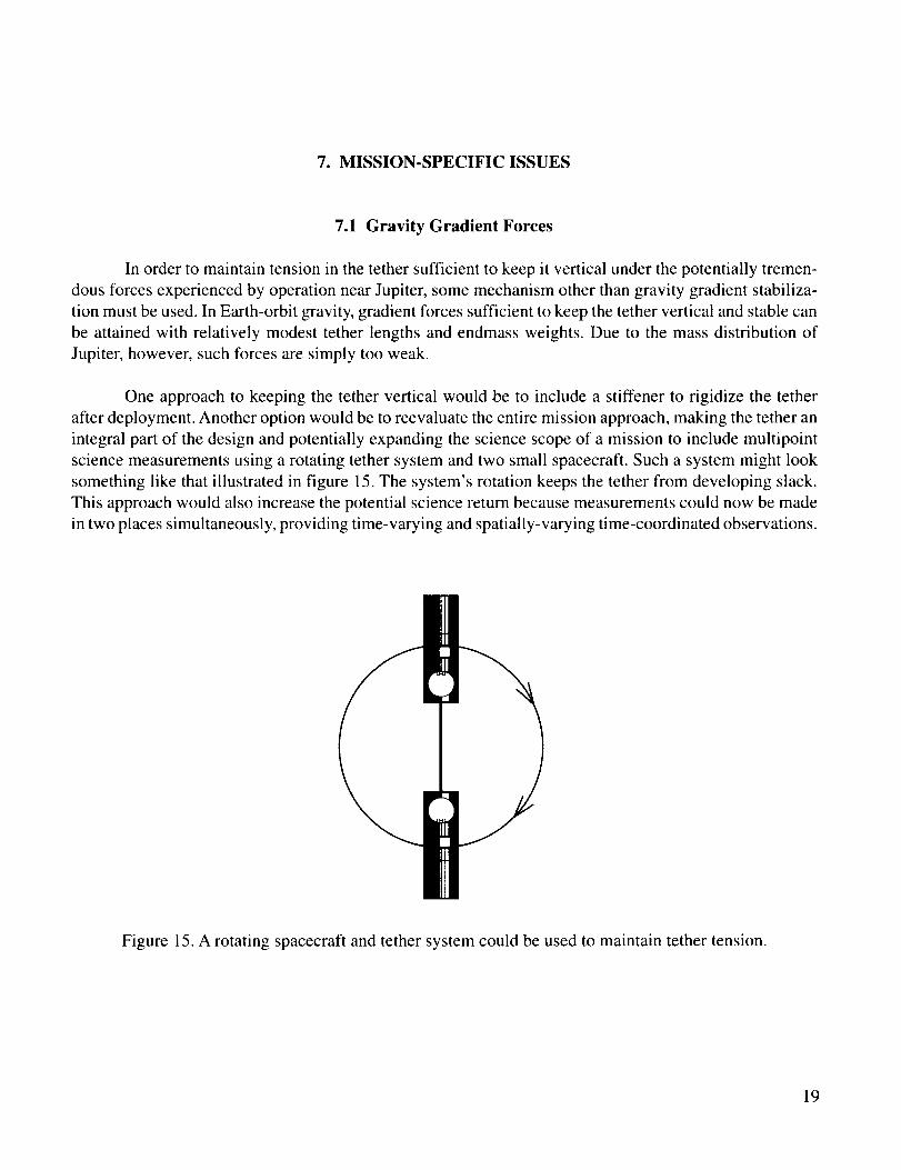
One approach to keeping the tether vertical would be to include a stiffener to rigidize the tether
after deployment. Another option would be to reevaluate the entire mission approach, making the tether an
integral part of the design and potentially expanding the science scope of a mission to include multipoint
science measurements using a rotating tether system and two small spacecraft. Such a system might look
something like that illustrated in figure 15. The system's rotation keeps the tether from developing slack.
This approach would also increase the potential science return because measurements could now be made
in two places simultaneously, providing time-varying and spatially-varying time-coordinated observations.
Figure 15. A rotating spacecraft and tether system could be used to maintain tether tension.
19

7.2 Micrometeoroid Threat
The threat of severing the tether by collision with a micrometeoroid is very real, as is the case with
all tethers operating in Earth orbit. With an impactor of one-third the tether diameter assumed to cause a
cut, the probability of survival for tethers of 1- and 10-mm diameter is shown in figure 16. Impactor
diameters of one-third and one-fifth the tether diameter were assessed.
P
m
¢o
a.
JovianTetherExamples
Time (yr)
Figure 16. The probability of survival for a single strand tether in near-Jovian space.
20

8. SUMMARY
The use of EDT's in the Jovian system, as shown in the artist's concept (fig. 17)' presents entirely new challenges and opportunities. In a circular orbit near the planet, it appears that induced tether voltages can reach as high as 50,000 V, currents can become greater than 20 A, power levels can reach over a million watts, and propulsive forces can reach higher than 50 N. Utilizing this tremendous power is clearly beyond current engineering capabilities.
Figure 17. Artist's concept of an electrodynamic tether-augmented spacecraft at Jupiter.
EDT's appear, on the basis of plasma physics, to be feasible for use in the Jovian magnetosphere. They also appear to present significant engineering challenges including:
High levels of tether current mean that managing a spacecraft system's thermal budget is not simple.
The complex geometry of forces that a tether would experience around Jupiter means that sophisticated control of tether current will be required in order to achieve specific mission orbital characteristics.
The capture analysis illustrates the potential for reasonably sized tethers to generate significant propulsive forces and tremendous, megawatt-level power generation.
The huge power levels predicted for the capture maneuver would require a relatively heavy tether system to handle the load. However, the weight of such a system could be justified for missions with very large power requirements.
• It alsoappearsfeasiblethatveryshorttethers(- 1km) couldbeutilized for generatingsubstan-tial power andorbital maneuveringcapabilities.Powergenerationvia tethermay providearealisticalternativeto RTG's.
• Theissueof tetherstabilityremainsopen.Gravity gradientforcesat Jupiterareinsufficienttomaintain tetherorientationandtensionunderthesepropulsiveloads.Alternativeconfigura-tions, includingarotatingsystem,shouldbeconsidered.
• Additionalanalysesshouldbeperformedto evaluatethebehaviorof atethersystemin loweraltitude,morecircularorbits.In thesetypesof orbitsit wouldbepossibleto providecontinuouspowerandpropulsiveforceswithout the requirementto dealwith thevery largepeaklevelsgeneratedin highly elliptic orbits.
22

9. RECOMMENDATIONS
Based on the study performed to evaluate the feasibility and merits of using an EDT for propulsion
and power generation for a spacecraft in the Jovian system, recommendations are as follows:
• A more specific and detailed characterization of EDT performance for propulsion and power
generation should be performed using mission-specific requirements.
• A rotating system with two spacecraft connected by a small-to-modest length tether should be
investigated. This should be closely coordinated with the science investigation team to opti-
mize both the tether engineering and the enhanced science return.
• Power management options should be examined in more detail to determine the limits of both
the tether and the power system.
• A detailed dynamic simulation should be developed to thoroughly understand the unique dy-
namic environment at Jupiter.
• Better physics models describing the plasma environment at Jupiter should be obtained and
integrated into the simulations.
23

REFERENCES
I° Johnson, L., et al.: "Electrodynamic Tethers for Reboost of the International Space Station and Space-
craft Propulsion," AIAA-96-4250, 1996 AIAA Space Program and Technologies Conference, Hunts-
ville, AL, September 24-26, 1996.
2. Parker, L.W.; and Murphy, B.L.: "Potential Buildup of an Electron-Emitting Ionospheric Satellite,"
Journal of Geophysical Research, Vol. 72, pp. 1631-1636, 1967.
3. Sanmartin, J.R.; Martinez-Sanchez, M.; and Ahedo, E.: "Bare Wire Anodes for Electrodynamic Teth-
ers," Journal of Propulsion and Power, Vol. 9, pp. 353-360, 1993.
4. Khurana, K.K.: "Euler Potential Models of Jupiter's Magnetospheric Field," Journal of Geophysical
Research, Vol. 102, pp. 11295-11306, 1997.
5. Bagenal, F.: "Empirical Model of the Io Plasma Torus: Voyager Measurements," Journal of Geophysi-
cal Research, Vol. 99, pp. 11043-11062, 1994.
6. Shiah, A.; Hwang, K.S.; Wu, S.T.; and Stone, N.H.: "Three-Dimensional Simulation of Current Collec-
tion in Space," Planet. Space Sci., Vol. 45, pp. 475-482, 1997.
7. Kliore, A.J.; Hinson, D.P.; Flasar, EM.; Nagy, A.E; and Cravens, T.E.: "The Ionosphere of Europa
From Galileo Radio Occultations," Science, Vol. 277, pp. 355-358, 1977.
8. Spilker, T.: "Jupiter Close Polar Orbiters: Preliminary Mission Studies," Outer Planets Science Work-
ing Group Meeting Summary, September 26, 1995.
24

REPORT DOCUMENTATION PAGE FormApp,'ovedOMBNo.0704-0188
Pubhc reporting burden for this collectionof information is estimated to average 1 hour per response, including the time for reviewing instructions, searching existing data sources,gathering and maintaining the data needed, and completing and reviewing the collection of information. Send comments regarding this burden estimate or any other aspect of thiscollection of information, including suggestions for reducing this burden, to Washington Headquarters Services, Directorate for Informalion Operation and Reports, 1215 JeffersonDavis Highway, Suite 1204, Arlington, VA 22202-4302, and to the Office of Management and Budget, Paperwork Reduction Prolect (0704-0188), Washington. DC 20503
1. AGENCY USE ONLY (Leave Blank) 2. REPORT DATE 3. REPORT TYPE AND DATES COVERED
June 1998 Technical Publication
4. TITLE AND SUBTITLE
Electrodynamic Tether Propulsion and Power Generation at Jupiter
6. AUTHORS
D.L. Gallagher, L. Johnson, J. Moore,* and F. Bagenal**
7. PERFORMING ORGANIZATION NAMES(S) AND ADDRESS(ES)
George C. Marshall Space Flight Center
Marshall Space Flight Center 35812
9.SPONSORING/MONITORINGAGENCYNAME(S)ANDADDRESS(ES)National Aeronautics and Space Administration
Washington, DC 20546-0001
5. FUNDING NUMBERS
8. PERFORMING ORGANIZATION
REPORT NUMBER
M-876
10. SPONSORING/MONITORINGAGENCY REPORT NUMBER
NASA/TP-- !998-208475
11. SUPPLEMENTARY NOTES
Prepared by Program Development Directorate
*SRS Technologies, **University of Colorado
12a. DISTRIBUTION/AVAILABILITY STATEMENT
Unclassified-Unlimited
Subject Category 20Standard Distribution
12b. DISTRIBUTION CODE
13. ABSTRACT (Maximum 200 words)
The results of a study performed to evaluate the feasibility and merits of using an
electrodynamic tether for propulsion and power generation for a spacecraft in the Jovian system
are presented. The environment of the Jovian system has properties which are particularly
favorable for utilization of an electrodynamic tether. Specifically, the planet has a strong
magnetic field and the mass of the planet dictates high orbital velocities which, when combined
with the planet's rapid rotation rate, can produce very large relative velocities between the
magnetic field and the spacecraft. In a circular orbit close to the planet, tether propulsive forces
are found to be as high as 50 N and power levels as high as i MW.
14. SUBJECT TERMS
tethers, electrodynamic propulsion, orbit transfer, power generation,
in-space transportation
17. SECURITY CLASSIFICATION
OF REPORT
Unclassified
NSN 7540-01-280-5500
18. SECURITY CLASSIFICATION
OF THIS PAGE
Unclassified
15. NUMBER OF PAGES
3216. PRICE CODE
A03t9. SECURITY CLASSIFICATION 20. LIMITATION OF ABSTRACT
OF ABSTRACT
Unclassified Unlimited
Standard Form 298 (Rev. 2-89)Prescribedby ANSIStd 239-18298-102


![Tether anthony[1]](https://static.fdocuments.net/doc/165x107/557c7d36d8b42a494c8b5161/tether-anthony1.jpg)


