
OF TETHER APPLICATIONS
47
GUIDEBOOK FOR ANALYSIS OF TETHER APPLICATIONS Joseph A. Carroll Final Report on Contract RH4-394049 with the Martin Marietta Corporation William Nobles, Technical Monitor March 1985 . 7L if <14L if ?14L if hanging release swinging release- spun or winched Effects of Tether Deployment and Release CONTENTS: PREFACE Generic Issues ORBIT BASICS Orbit Equations Perturbations Aerodynamic Drag Thermal Balance Micrometeoroids & Debris TETHER DYNAMICS Gravity Gradients Dumbbell Libration Control Strategies Momentum Transfer Orbit Transfer Energy Balance THE TETHER ITSELF Strength & Mass I Impact Hazards I ELECTRODYNAMICS Basic Principles Orbit Changes Libration Control BIBLIOGRAPHY
Transcript of OF TETHER APPLICATIONS

GUIDEBOOK FOR ANALYSISOF TETHER APPLICATIONS
Joseph A. Carroll
Final Report on Contract RH4-394049with the Martin Marietta CorporationWilliam Nobles, Technical Monitor
March 1985
.7L if
<14L if?14L if
hanging releaseswinging release-spun or winched
Effects of Tether Deployment and Release
CONTENTS:
PREFACE
Generic Issues
ORBIT BASICS
Orbit Equations
Perturbations
Aerodynamic Drag
Thermal Balance
Micrometeoroids& Debris
TETHER DYNAMICS
Gravity Gradients
Dumbbell Libration
Control Strategies
Momentum Transfer
Orbit Transfer
Energy Balance
THE TETHER ITSELF
Strength & Mass I
Impact Hazards I
ELECTRODYNAMICS
Basic Principles
Orbit Changes
Libration Control
BIBLIOGRAPHY

PREFACE
This Guidebook is intended as a tool to facilitate initial analyses ofproposed tether applications in space. The guiding philosophy is thatat the beginning of a study effort, a brief analysis of ALL the commonproblem areas is far more useful than a detailed study in any one area.Such analyses can minimize the waste of resources on elegant but fatallyflawed concepts, and can identify the areas where more effort is neededon concepts which do survive the initial analyses.
In areas in which hard decisions have had to be made, the Guidebook is:
Broad, rather than deepSimple, rather than preciseBrief, rather than comprehensiveIllustrative, rather than definitive
Hence the simplified formulas, approximations, and analytical tools includedin the Guidebook should be used only for preliminary analyses. For detailedanalyses, the references with each topic & in the bibliography may be useful.Note that topics which are important in general but not particularly relevantto tethered systems analysis (e.g., radiation dosages) are not covered.
CREDITS
This Guidebook was prepared by the author under subcontract RH4-394049 withthe Martin Marietta Corporation, as part of its contract NAS8-35499 (Phase IIof a Study of Selected Tether Applications in Space) with the NASA MarshallSpace Flight Center. Some of the material was adapted from references listedwith the various topics, and this assisted the preparation greatly. Much ofthe other material evolved or was clarified in discussions with one or more ofthe following: Dave Arnold, James Arnold, Ivan Bekey, Guiseppe Colombo, MiltContella, Dave Criswell, Don Crouch, Andrew Cutler, Mark Henley, Don Kessler,Harris Mayer, Jim McCoy, Bill Nobles, Tom O’Neil, Paul Penzo, Jack Slowey,Georg von Tiesenhausen, and Bill Thompson. The author is of course responsiblefor all errors, and would appreciate being notified of any that are found.New address and phone number:
J o s e p h A . C a r r o l l Joseph A. CarrollEnergy Sc i ence Laborator i es , In c e Energy Science LaboratoriesP.O. Box 85608San Diego, C A 92138-5608
11404 Sorrento Valley Rd, 8113
6 1 9 - 4 5 5 - 4 6 8 8San Diego, CA 92121619-452-7039
-i-
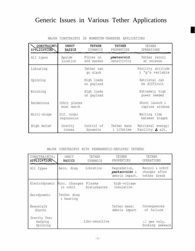
Generic Issues in Various Tether Applications
MAJOR CONSTRAINTS IN MOMENTUM-TRANSFER APPLICATIONS
TETHERDYNAMICS PROPERTIES OPERATIONS
All types Apside Forces on rmeteoroid Tether recoillocation end masses sensitivity at release
Librating Tether can Facility attitudego slack & "g"s variable
Spinning High loads Retrieval canon payload be difficult
Winching High loads Extremely highon payload power needed
Rendezvous Orbit planes Short launch &must match capture windows
Multi-stage Dif. nodal Waiting timeregression between stages
High deltaV Gravity Control of Tether mass Retrieval energy;losses dynamics & lifetime Facility A alt.
MAJOR CONSTRAINTS WITH PERMANENTLY-DEPLOYED TETHERS
CONSTRAINTS: ORBIT TETHER TETHER TETHERDYNAMICS PROPERTIES OPERATIONS
All types Aero. drag Libration Degradation, Recoil & orbitpmeteoroids & changes afterdebris impact. tether break
Electrodynamic Misc. changes Plasma High-voltagein orbit disturbances insulation
Aerodynamic Tether drag& heating
Beanstalk(Earth)
Gravity Use:HangingSpinning
Tether mass; Consequencesdebris impact of failure
Libr-sensitive <.1 gee only.Docking awkward
-l-

KEY POINTSBasic orbit nomenclature & equations are needed frequently in following pages.Comparison of tether & rocket operations requires orbit transfer equations.
The figures and equations at right are a summary of the aspects of orbitalmechanics most relevant to tether applications analysis. For more completeand detailed treatments and many of the derivations, consult refs l-3.
The first equation in the box is known as the Vis Viva formulation, and tothe right of it is the equation for the mean orbital angular rate, n. Much ofthe analysis of orbit transfer AVs and tether behavior follows from those twosimple equations. Some analyses require a close attention to specific angularmomentum, h, so an expression for h (for compact objects) is also given here.
NOTES
In general, six parameters are needed to completely specify an orbit. Variousparameter sets can be used (e.g., 3 position coordinates & 3 velocity vectors).The six parameters listed at right are commonly used in orbital mechanics.Note that when i=O, .G, becomes indeterminate (and unnecessary); similarly withw when e=O. Also, i & 0, are here referenced to the central body’s equator, asis usually done for Low Earth Orbit (LEO). For high orbits, the ecliptic orother planes are often used. This simplifies calculation of 3rd body effects.
The effects of small AVS on near-circular orbits are shown at right. The rela-tive effects are shown to scale: a AV along the velocity vector has a maximumperiodic effect 4 times larger than that of the same AV perpendicular to it(plus a secular effect in 9 which the others don’t have). Effects of obliqueor consecutive AVS are simply the sum of the component effects. Note that out-of-plane AVS at a point other than a node also affect &
For large AVS, the calculations are more involved. The perigee and apogeevelocities of the transfer orbit are first calculated from the Vis Viva formu-lation and the constancy of h. Then the optimum distribution of plane changebetween the two AVS can be computed iteratively, and the required total AVfound. Typically about 90% of the plane change is done at GEO.
To find how much a given in-plane tether boost reduces the required rocket A+,the full calculation should be done for both the unassisted and the tether-assisted rocket. This is necessary because the tether affects not only theperigee velocity, but also the gravity losses and the LEO/GE0 plane changesplit. Each m/s of tether boost typically reduces the required rocket boostby .89 m/s (for hanging release) to .93 m/s (for widely librating release).
Note that for large plane changes, and large radius-ratio changes even withoutplane changes, S-impulse “bi-elliptic” maneuvers may have the lowest total AV.Such maneuvers involve a boost to near-escape, a small plane and/or perigee-adjusting AV at apogee, and an apogee adjustment (by rocket or aerobrake) atthe next perigee. In particular, this may be the best way to return aero-braking OTVs from GE0 to LEO, if adequate time is available.
.
REFERENCES ::3.
A.E. Roy, Orbital Motion, Adam Hilger Ltd., Bristol, 1978.Bate, Mueller, & White, Fundamentals of Astrodynamics, Dover Pub., 1971,M.H. Kaplan, Modern Spacecraft Dynamics & Control, John Wiley & Sons, 1978.
-2-

Orbit & Orbit Transfer Equations
raw=a(l+e) rper=a(l-e)
p=a(l-e*)
v*= )I($-$) I-d+?h =E = r26 = rVcos$
I ^V~irc= r/rI
peart-,=3Y3601 km3/sec*V& = *p/r PX = G * Mass of x
BASIC ORBIT EQUATIONS
M= M,+nt Satelliteositionat t=O
Peria sisFDirec ion
ORBITAL ELEMENTS
a = semi-major axise = eccentricityi = inclination.Gl= long. of asc. nodew = argument of periapsit$,= position at epoch
Effects of Small AVs on Near-Circular Orbits
Total AV is minimized when 51” = %E;a‘U-I yGE0 'GE0
Large Orbit Transfers (e.g., LEO-GEO)
-3-

Differential nodal regression severely limits coplanar rendezvous windows.KEY POINTS Apsidal recession affects STS deboost requirements from elliptical orbits.
Third bodies can change the orbit plane of high-orbit facilities.
The geoid (earth’s shape) is roughly that of a hydrostatic-equilibrium oblateellipsoid, with a 296:297 polar:equatorial radius ratio. There are departuresfrom this shape, but they are much smaller than the 1:297 oblateness effectand have noticeable effects only on geosynchronous and other resonant orbits.
The focus here is on oblateness, because it is quite large and because it haslarge secular effects on fi and w for nearly all orbits. (Oblateness alsoaffects n, but this can usually be ignored in preliminary analyses.) As shownat right, satellites orbiting an oblate body are attracted not only to itscenter but also towards its equator. This force component imposes a torque onall orbits that cross the equator at an angle, and causes the direction of theorbital angular momentum vector to regress as shown.
n is largest when i is small, but the plane change associated with a given nfIvaries with sin i. Hence the actual plane change rate varies with sini cosi,or Sin2i, and is highest near 45’. For near-coplanar rendezvous in LEO,the required out-of-plane AV changes by 78 sin 2i m/s for each phasing “lap”,This is independent of the altitude difference (to first order), since phasing& differential nodal regression rates both scale with ba. Hence even at besta rendezvous may require an out-of-plane AV of 39 m/s. At other times, out-of-plane AVS of 2 sin i sin(&/2) Vcirc (=up to 2 V,irc!) are needed.
NOTES The linkage between phasing and nodal regression rates is beneficial in somecases: if an object is boosted slightly and then allowed to decay until itpasses below the boosting object, the total c,Q is nearly identical for both.Hence recapture need not involve any significant plane change.
Apsidal recession generally has a much less dominant effect on operations,since apsidal adjustments (particularly of low-e orbits) involve much lowerAVS than nodal adjustments. However, tether payload boosts may often be donefrom elliptical STS orbits, and perigee drift may be an issue. For example,OMS deboost requirements from an elliptical STS orbit are tonnes lower (andpayload capability much higher) if perigee is near the landing site latitudeat the end of the mission. Perigee motion relative to day/night variationsis also important for detailed drag calculations, and for electrodynamic day-night energy storage (where it smears out and limits the eccentricity-pumpingeffect of a sustained day-night motor-generator cycle).
Just as torques occur when the central body is non-spherical, there are alsotorques when the satellite is non-spherical. These affect the satellite’s spinaxis and cause it to precess around the orbital plane at a rate that dependson the satellite’s mass distribution and spin rate.
In high orbits, central-body perturbations become less important and 3rd-bodyeffects more important. In GEO, the main perturbations (-47 m/s/yr) are causedby the moon and sun. The figure at right shows how to estimate these effects,using the 3rd body orbital plane as the reference plane.
REFERENCES 1. A.E. Roy, Orbital Motion, Adam Hilger Ltd., Bristol, 1978.2. Bate, Mueller, & White, Fundamentals of Astrodynamics, Dover Pub., 1971,
-4-

Orbital Perturbations
Nodal Regression in LEO:
For sun-synchronous orbits: (i=lOO"+?)
cos i5 -.0988(a/re)3’5(1-e2)2
For coplanar low-AV rendezvousbetween 2 objects (e,=e,zU, i,=iz),nodal coincidence intervals are:
180 (ahe) 4.5Atnc s Aa lcos il
kmayrs
.OBLATENESS CAUSES LARGESECULAR CHANGES IN h&W:
h:up to 1 rad./week in LEO
&up to 2 rad./week in LEO
Aosidal recession in LEO:
cj, 63.6(2-2.5 sin%(a/re)3*5 (l-e21
2) rad/yr
i<63.4' k63.4' i>63.4O
Motion of the longitude ofperigee with respect to thesun's direction ("noon") is:
&-/Third-Body Perturbations (non-resonant orbits)

Tether drag affects tether shape & orbital life; at. oxygen degrades tethers.
KEY POINTSOut-of-plane drag component can induce out-of-plane tether libration.The main value of payload boosting by tether is the increased orbital life.Unboosted orbital life of space facilities is affected by tether operations.
The figure at right shows the orbiter trolling a satellite in the atmosphere,as is planned for the 2nd TSS mission in the late 1980s. The tether draggreatly exceeds that on the end-masses and should be estimated accurately.The drag includes a small out-of-plane component that can cause #-libration.
Tether drag is experienced over a range of altitudes, over which most of theterms in the drag equation vary: the air density& the airspeed Vrel, andthe tether width & angle of attack. In free-molecular flow, CL is small,and CD (if based on A3 is nearly constant at 2.2. (CD rises near grazingincidence, but then Al is low.)
Only,o varies rapidly, but it varies in a way which lends itself to simpleapproximations. Empirical formulae have been developed by the author and areshown at right. They give values that are usually within 25% of ref. 1, whichis still regarded as representative for air density as a function of altitude& exosphere temperature. These estimates hold only forp>lE-14, beyond whichhelium & hydrogen dominate & the density scale height H increases rapidly.
NOTESNote that over much of LEO, atomic oxygen is the dominant species. Hyperther-ma1 impact of atomic oxygen on exposed surfaces can cause rapid degradation,and is a problem in low-altitude applications of organic-polymer tethers.
The space age began in 1957 at a 200-yr high in sunspot count. A new estimateof mean solar cycle temperatures (at right, from ref. 2), is much lower thanearlier estimates. Mission planning requires both high & mean estimates forproper analysis. Ref. 2 & papers in the same volume discuss models now in use.
If the tether length L is <XII, the total tethered system drag can be estimatedfrom the total Al & the midpoint V &p. If L>>H, the top end can be neglected,the bottom calculated normally, and the tether drag estimated from l.l/obottom* tether diameter * H * V2rel, with H & Vrel evaluated one H above the bottomof the tether. For L between these cases, the drag is bounded by these cases.
As shown at right, the orbital life of more compact objects (such as might beboosted or deboosted by tether) can be estimated analytically if T,, is known.For circular orbits with the same r, Vrel &p both vary with i, but thesevariations tend to compensate & can both be ignored in first-cut calculations.
The conversion of elliptical to “equal-life” circular orbits is an empiricalfit to an unpublished parametric study done by the author. It applies whenapsidal motions relative to the equator and relative to the diurnal bulge arelarge over the orbital life; this usually holds in both low & high-i orbits.For a detailed study of atmospheric drag effects, ref. 3 is still useful.
L U.S. Standard Atmosphere Supplements, 1966. ESSA/NASA/USAF, 1966.2. K. S. W Champion, “Properties of the Mesosphere and Thermosphere and
REFERENCES Comparison with CIRA 72”,, in The Terrestrial Upper Atmosphere, Championand Roemer, ed.; Vol 3, #l of Advances in Space Research, Pergamon, 1983.
3. D.G. King-Hele, Theory of Satellite Orbits in an Atmosphere, Butterworths,London, 1964.

-%_r
F Width &
-~-'z+z=---/--z+-----_.465 Cos(Lat) km/set-5/ , .’ _ ,A </',
t3
US Standard AtmMain ga:species
- -:?.881ex1?7G 1962 tgn mass):
$
FlfA\.firk
\ 'lOdO '1600 KPredicted Global Tex for .- 0, N2
Aerodynamic Drag
Lift & Drag in Free-Molecular
(x.))D
Flow
1 o-4+
10+
Kg10-8--
m3
10''O--
lo-l*--
Altitude in KmAir Density as Function of Altitude & Exosphere Temperature
70<Alt<118:,o Hllexp(-Alt/6)118<Alt<200:,o e(Alt-95)~?2600
-p/b = H = 6 (km)H = (Alt-95113
200<Alt &,,o>lE-14 l
P@ H = l 1(A1t-200)+Tex’2g
Circular 2Orbit Life % l 'l5 m yr _!L!_ (1 + 2.9(r-6578)/Tex)"
(-14uoep<-10) kg 'DA3000 - Tex
Equal-Life -Perigee + Apo - PerCirc. Alt. 2 + .154(Apo-Per)/Hper
-7-

Aerothermal heating of tethers is severe at low altitudes (<120 km).
KEY POINTS Tether temperature affects strength, toughness, & electrical conductivity.Extreme thermal cycling may degrade pultruded composite tethers.“View factors” are also used in refined micrometeoroid risk calculations.
Preliminary heat transfer calculations in space are often far simpler thantypical heat transfer calculations on the ground, since the complicationsintroduced by convection are absent. However the absence of the “clamping”effect of large convective couplings to air or liquids allows very high orlow temperatures to be reached, and makes thermal design important.
At altitudes below about 140 km in LEO, aerodynamic heating is the dominantheat input on surfaces facing the ram direction. The heating scales withpas long as the mean free path A is much larger than the object’s radius. Itis about equal to the energy dissipated in stopping incident air molecules.In denser air, shock & boundry layers develop. They shield the surface fromthe incident flow and make Q rise slower asp increases further. (See ref 1.)
Because tethers are narrow, they can be in free molecular flow even at 100 km,and may experience more severe heating than the (larger) lower end masses do.Under intense heating high temperature gradients may occur across non-metallictethers. These gradients may cause either overstress or stress relief on thehot side, depending on the sign of the axial thermal expansion coefficient.
NOTES At higher altitudes the environment is much more benign, but bare metal (low-emittance) tethers can still reach high temperatures when resistively heatedor in the sun, since they radiate heat poorly. Silica, alumina, or organiccoatings >l urn thick can increase emittance and hence reduce temperatures.The temperature of electrodynamic tethers is important since their resistancelosses (which may be the major system losses) scale roughly with Tabs.
For a good discussion of solar, albedo, and longwave radiation, see ref. 2.The solid geometry which determines the gains from these sources is simple butsubtle, and should be done carefully. Averaged around a tether, earth view-factors change only slowly with altitude & attitude, and are near .3 in LEO.
Surface property changes can be an issue in long-term applications, due tothe effects of atomic oxygen, UV & high-energy radiation, vacuum, depositionof condensible volatiles from nearby surfaces, thermal cycling, etc. Hyper-thermal atomic oxygen has received attention only recently, and is now beingstudied in film, fiber, and coating degradation experiments on the STS & LDEF.
Continued thermal cycling over a wide range (such as shown at bottom right)may degrade composite tethers by introducing a maze of micro-cracks. Also,temperature can affect the strength, stiffness, shape memory, and toughness oftether materials, and hence may affect tether operations and reliability.
1. R.N. Cox & L.F. Crabtree, Elements of Hypersonic Aerodynamics, The EnglishUniversities Press Ltd, London, 1965. See esp. Ch 9, “Low Density Effects”
REFERENCES 2. F.S. Johnson, ed., Satellite Environment Handbook, Second Edition, StanfordUniversity Press, 1965. See chapters on solar & earth thermal radiation.
3. RC. Hottel, “Radiant Heat Transmission,” Chapter 4 of W.H.. McAdams, HEATTRANSMISSION, 3rd edition, McGraw-Hill, New York, 1954, pp. 55-125.
-8-

Thermal Balance
b= 5.68E-8 W/mLK)
solar =
internal q
1 G--'aerodyn. =
albedo =
earth =
ttFl1 = Shaded fractionof sphere or itsprojection onto
_appropriate circle,
Fraction oftime in sun
Maximum Sun
1368 (&O) p,Al W/m2 (if in sun)q.1 - .9 (Kevlar z.4)
ohmic + any others
.5p h_V;el (see "Aero, Drag")
.37 (2.3) * 1368 h40) W/m2* $A F Cos(SunZenithAngle) (if >0)
215 (&loo) A 6 F W/m2
F ,.
Altitude in KmEarth Viewfactors in LEO
260
240D"g 220
K 200
180
Earth Viewfactors for Tethers
Deg. past "Midnight"Tether Temperature Over 1 Orbit
(f3 i Sun out-of-plane angle)
-9-

KEY POINTSMicrometeoroids can sever thin tethers & damage tether protection/insulation.Orbiting debris can sever tethers of any diameter.
At the start of the space age, estimates of. meteoroid fluxes varied widely.Earth was thought to have a dust cloud around it, due to misinterpretation ofdata such as microphone noise caused by thermal cycling in spacecraft. By thelate 1960s most meteoroids near earth were recognized to be in heliocentricrather than geocentric orbit. The time-averaged flux is mostly sporadic, butmeteor showers can be dominant during their occurrence.
There is a small difference between LEO and deep-space fluxes, due to thefocusing effect of the earth’s gravity (which increases the velocity & flux),and the partial shielding provided by the earth & “sensible” atmosphere. Fora typical meteoroid velocity of 20 km/sec, these effects combine to make therisk vary as shown at right in LEO, GEO, and beyond. The picture of a metalplate after hypervelocity impact is adapted from ref. 3.
NOTES
The estimated frequency of sporadic meteoroids over the range of interest formost tether applications is shown by the straight line plot at right, which isadapted from ref. 4 & based on ref. l. (Ref 1 is still recommended for designpurposes.) For masses<lE-6 gm (c.15 mm diam. at an assumed density of .5), thefrequency is lower than an extension of that line, since several effects clearvery small objects from heliocentric orbits in geologically short times.
Over an increasing range of altitudes and particle sizes in LEO, the mainimpact hazard is due not to natural meteoroids but rather to man-made objects.The plots at right, adapted from refs 4 & 5, show the risks presented by the5,000 or so objects tracked by NORAD radars (see ref. 6). A steep “tail” inthe 1995 distribution is predicted since it is likely that several debris-generating impacts will have occurred in LEO before 1995. Such impacts areexpected to involve a 4-40 cm object striking one of the few hundred largestobjects and generating millions of small debris fragments.
Recent optical detection studies which have a size threshold of about 1 cmindicate a population of about 40,000 objects in LEO. This makes it likelythat debris-generating collisions have already occurred. Studies of residuein small surface pits on the shuttle and other objects recovered from LEOindicate that they appear to be due to titanium, aluminum, and paint fragments(perhaps flaked off satellites by micrometeoroid hits). Recovery of the LongDuration Exposure Facility (LDEF) later this year should improve this databasegreatly, and will provide data for LEO exposure area-time products comparableto those in potential long-duration tether applications.
1.
2.REFERENCES
3.4.
5.6.
Meteoroid Environment Model-1969 [Near Earth to Lunar Surface], NASASP-8013, March 1969.Meteoroid Environment Model-1970 [Interplanetary and Planetary], NASASP-8038, October 1970.
Meteoroid Damage Assessment, NASA SP-8042, May 1970. Shows impact effects.D. J. Kessler, “Sources of Orbital Debris and the Projected Environment forFuture Spacecraft”, in J. of Spacecraft & Rockets, Vol 18 #4, Jul-Aug 1981.D. J. Kessler, Orbital Debris Environment for Space Station, JSC-20001, 1984.CLASSY Satellite Catalog Compilations. Issued monthly by NORAD/J5YS,Peterson Air Force Base, CO 80914.
-lO-

Micrometeoroids & Debris
.oo100 200 400 600 800 1000
Altitude in KmRelative pm Risks in LEO
BelRisk s (1 -Fearth)(.57+.43re/r)l
Population Correctedto 4 cm Limiting Size
loeqo I I , , 1 I I500 lau I5al mN
Altitude, cI(*) 15w 4un
Observed Debris Flux(corrected to 4-cm limiting size)
Altitude q 500 kmInclination: 30" -
60" ___.
km/secDebris Impact Velocity
,0-811 I 1 I 1
10-z Ml- I
Threshol: Diame&, cmIO2 I O ’
Cumulative Flux in 1995 (60~1100 km)
Orbital Motion B
KEY POINTS “Microgee” environments are possible only in small regions (-5 m) of a LEO facility.Milligee-level gravity is easy to get & adequate for propellant settling, etc.
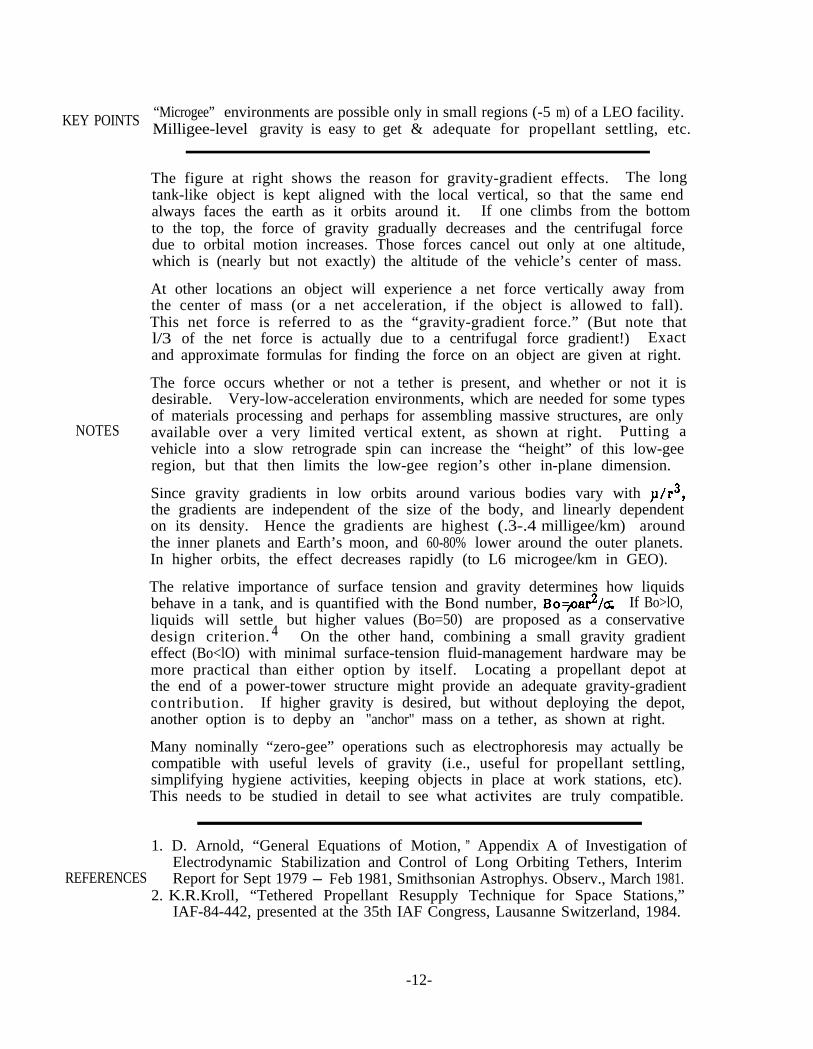
The figure at right shows the reason for gravity-gradient effects. The longtank-like object is kept aligned with the local vertical, so that the same endalways faces the earth as it orbits around it., If one climbs from the bottomto the top, the force of gravity gradually decreases and the centrifugal forcedue to orbital motion increases. Those forces cancel out only at one altitude,which is (nearly but not exactly) the altitude of the vehicle’s center of mass.
At other locations an object will experience a net force vertically away fromthe center of mass (or a net acceleration, if the object is allowed to fall).This net force is referred to as the “gravity-gradient force.” (But note thatl/3 of the net force is actually due to a centrifugal force gradient!) Exactand approximate formulas for finding the force on an object are given at right.
NOTES
The force occurs whether or not a tether is present, and whether or not it isdesirable. Very-low-acceleration environments, which are needed for some typesof materials processing and perhaps for assembling massive structures, are onlyavailable over a very limited vertical extent, as shown at right. Putting avehicle into a slow retrograde spin can increase the “height” of this low-geeregion, but that then limits the low-gee region’s other in-plane dimension.
Since gravity gradients in low orbits around various bodies vary with p/r3,the gradients are independent of the size of the body, and linearly dependenton its density. Hence the gradients are highest (.3-.4 milligee/km) aroundthe inner planets and Earth’s moon, and 60-80% lower around the outer planets.In higher orbits, the effect decreases rapidly (to L6 microgee/km in GEO).
The relative importance of surface tension and gravity determines how liquidsbehave in a tank, and is quantified with the Bond number, Bovar2/a If Bo>lO,liquids will settledesign criterion. 4
but higher values (Bo=50) are proposed as a conservativeOn the other hand, combining a small gravity gradient
effect (Bo<lO) with minimal surface-tension fluid-management hardware may bemore practical than either option by itself. Locating a propellant depot atthe end of a power-tower structure might provide an adequate gravity-gradientcontribution. If higher gravity is desired, but without deploying the depot,another option is to depby an "anchor" mass on a tether, as shown at right.
Many nominally “zero-gee” operations such as electrophoresis may actually becompatible with useful levels of gravity (i.e., useful for propellant settling,simplifying hygiene activities, keeping objects in place at work stations, etc).This needs to be studied in detail to see what activites are truly compatible.
1. D. Arnold, “General Equations of Motion, ” Appendix A of Investigation ofElectrodynamic Stabilization and Control of Long Orbiting Tethers, Interim
REFERENCES Report for Sept 1979 - Feb 1981, Smithsonian Astrophys. Observ., March 1981.2. K.R. Kroll, “Tethered Propellant Resupply Technique for Space Stations,”
IAF-84-442, presented at the 35th IAF Congress, Lausanne Switzerland, 1984.
-12-

Gravity Gradient Effects
Fcentrifugal = fi = Mn2r_
“Gravity-gradient”
(213 gravity& l/3 ceritrif.)
Fgg = F+F&== 3LMn2
--=t
ltGravity-gradientl’
‘g rav i ty = F$ = Mp/r‘
Origin of llGravity-Gradient’l Forces -=.------
AttachDepot
%
<low7 gee1 over .5 m
<1o-5over
gee50 m
Magnitude ofGravity GradientEffects in LEO
3tCalcium RetentiorCrystal Growth+! *
It- walk5ngLatex Reactors! )', *
‘?C- 19esktop11 work
Hygiene
.Fluid Settling
Microgravity'- ld3 G '5'ull Gravity
Potential Overlap of Regions forLow-Gee & Gee-Dependent Operations
Two Propellant-Settling Options-13-
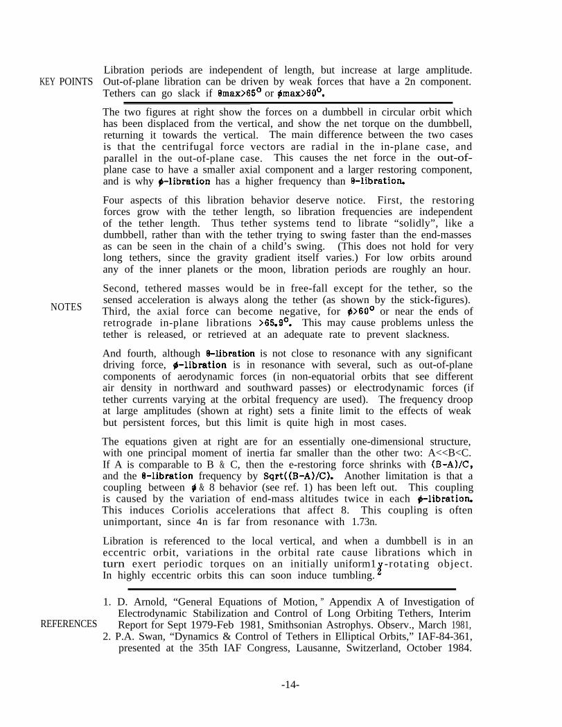
Libration periods are independent of length, but increase at large amplitude.KEY POINTS Out-of-plane libration can be driven by weak forces that have a 2n component.
Tethers can go slack if 0max>6S0 or $max>60°.
The two figures at right show the forces on a dumbbell in circular orbit whichhas been displaced from the vertical, and show the net torque on the dumbbell,returning it towards the vertical. The main difference between the two casesis that the centrifugal force vectors are radial in the in-plane case, andparallel in the out-of-plane case. This causes the net force in the out-of-plane case to have a smaller axial component and a larger restoring component,and is why #-libration has a higher frequency than 8-libration.
Four aspects of this libration behavior deserve notice. First, the restoringforces grow with the tether length, so libration frequencies are independentof the tether length. Thus tether systems tend to librate “solidly”, like adumbbell, rather than with the tether trying to swing faster than the end-massesas can be seen in the chain of a child’s swing. (This does not hold for verylong tethers, since the gravity gradient itself varies.) For low orbits aroundany of the inner planets or the moon, libration periods are roughly an hour.
Second, tethered masses would be in free-fall except for the tether, so the
NOTESsensed acceleration is always along the tether (as shown by the stick-figures).Third, the axial force can become negative, for #>60° or near the ends ofretrograde in-plane librations >65.9’. This may cause problems unless thetether is released, or retrieved at an adequate rate to prevent slackness.
And fourth, although 8-libration is not close to resonance with any significantdriving force, g-libration is in resonance with several, such as out-of-planecomponents of aerodynamic forces (in non-equatorial orbits that see differentair density in northward and southward passes) or electrodynamic forces (iftether currents varying at the orbital frequency are used). The frequency droopat large amplitudes (shown at right) sets a finite limit to the effects of weakbut persistent forces, but this limit is quite high in most cases.
The equations given at right are for an essentially one-dimensional structure,with one principal moment of inertia far smaller than the other two: A<<B<C.If A is comparable to B & C, then the e-restoring force shrinks with (B-A)/C,and the 8-libration frequency by Sqrt((B-A)/C). Another limitation is that acoupling between 9 & 8 behavior (see ref. 1) has been left out. This couplingis caused by the variation of end-mass altitudes twice in each #-librationThis induces Coriolis accelerations that affect 8. This coupling is oftenunimportant, since 4n is far from resonance with 1.73n.
Libration is referenced to the local vertical, and when a dumbbell is in aneccentric orbit, variations in the orbital rate cause librations which inturn exert periodic torques on an initially uniform1 -rotating object.In highly eccentric orbits this can soon induce tumbling. H
1. D. Arnold, “General Equations of Motion, ” Appendix A of Investigation ofElectrodynamic Stabilization and Control of Long Orbiting Tethers, Interim
REFERENCES Report for Sept 1979-Feb 1981, Smithsonian Astrophys. Observ., March 1981,2. P.A. Swan, “Dynamics & Control of Tethers in Elliptical Orbits,” IAF-84-361,
presented at the 35th IAF Congress, Lausanne, Switzerland, October 1984.
-14-

Dumbbell Libration in Circular Orbit
Fnet
.‘
0 B -3n*sin0 cos0 = -1.5n2sin(20)
i, = +fi n sin*0max-sin20
(6 =+fi n sin0max when f3=0>
ne = n)/3cosemax
T ='3LMn*i ’ . 1
“.d”.
0 15 3i, 45 60 75 900, Deg from Vertical
Fnet rl‘i&II'rF centrifugalI
<gravity-t4
,:ie!
3-_ -4n*sin$ co@ = -*n*sin(*#)
3s k*nJsin*$max-sin*$
(+**n sin#max when $=O>
nN= *n+$iYiE
I \(4cos#max
“eln 1.001
0.50.
o.oo(
-1.6 cycles/orbitfor Bmax = 30"
c1 15 30 45 60 75
Deg. Amplitude,0 or+
Tension Variations in Librating Dumbbells(compared to tension in hanging dumbbells)
Libration Freq. vs Amplitude
-15-
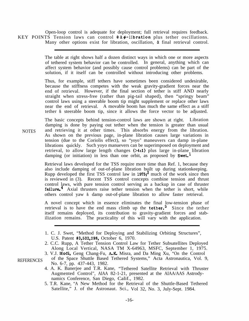
Open-loop control is adequate for deployment; full retrieval requires feedback.KEY POINTS Tension laws can control 9 & #-libration plus tether oscillations.
Many other options exist for libration, oscillation, & final retrieval control.
The table at right shows half a dozen distinct ways in which one or more aspectsof tethered system behavior can be controlled. In general, anything which canaffect system behavior (and possibly cause control problems) can be part of thesolution, if it itself can be controlled without introducing other problems.
Thus, for example, stiff tethers have sometimes been considered undesirable,because the stiffness competes with the weak gravity-gradient forces near theend of retrieval. However, if the final section of tether is stiff AND nearlystraight when stress-free (rather than pig-tail shaped), then “springy beam”control laws using a steerable boom tip might supplement or replace other lawsnear the end of retrieval. A movable boom has much the same effect as a stifftether & steerable boom tip, since it allows the force vector to be adjusted.
NOTES
The basic concepts behind tension-control laws are shown at right. Librationdamping is done by paying out tether when the tension is greater than usualand retrieving it at other times. This absorbs energy from the libration.As shown on the previous page, in-plane libration causes large variations intension (due to the Coriolis effect), so “yoyo" maneuvers can damp in-planelibrations quickly. Such yoyo manuevers can be superimposed on deployment andretrieval, to allow large length changes (>4:1) plus large in-plane librationdamping (or initiation) in less than one orbit, as proposed by Swet.’
Retrieval laws developed for the TSS require more time than Ref. 1, because theyalso include damping of out-of-plane libration built up during stationkeeping.Rupp developed the first TSS control law in 1975;’ much of the work since thenis reviewed in (3). Recent TSS control concepts combine tension and thrustcontrol laws, with pure tension control serving as a backup in case of thrusterfailure.4 Axial thrusters raise tether tension when the tether is short, whileothers control yaw & damp out-of-plane libration to allow faster retrieval.
A novel concept which in essence eliminates the final low-tension phase ofretrieval is to have the end mass climb up the tether.5 Since the tetheritself remains deployed, its contribution to gravity-gradient forces and stab-ilization remains. The practicality of this will vary with the application.
1. C. J. Swet, “Method for Deploying and Stabilizing Orbiting Structures”,U.S. Patent #3,532,298, October 6, 1970.
2. C.C. Rupp, A Tether Tension Control Law for Tether Subsatellites DeployedAlong Local Vertical, NASA TM X-64963, MSFC, September 1, 1975.
3. V.J. Modi, Geng Chang-Fu, A.K. Misra, and Da Ming Xu, “On the Control
REFERENCES of the Space Shuttle Based Tethered Systems,” Acta Astronautica, Vol. 9,No. 6-7, pp. 437-443, 1982.
4. A. K. Banerjee and T.R. Kane, “Tethered Satellite Retrieval with ThrusterAugmented Control", AIAA 82-1-21, presented at the AIAA/AAS Astrody-namics Conference, San Diego, Calif., 1982.
5. T.R. Kane, “A New Method for the Retrieval of the Shuttle-Based TetheredSatellite,” J. of the Astronaut. Sci., Vol 32, No. 3, July-Sept. 1984.
-16-

Tether Control Strategies
EFFECTIVENESS OF VARIOUS CONTROL CONCEPTS
Libration Tether Oscillations Endmass Attitude Osc,In-plane (Out-of-plane Longitudinal[Transverse Pitch & Roll Yaw
*I I
Tension Strong Weak Strong Strong Strong None(Note: tension control is weak when tether is short),
f ;;:,I;;yt 11 Only if Ml # M2 11 Nonei%fijifi!& str;;;;riyknE;;;;y
Strong, but costly if prolonged
Movable mass Good w/short tether Possible but awkward None None
I Stiff tether,Movable boom I
Strong if tether is very short; weak otherwise
I AerodynamicI
High drag- use only if low altitude needed for other reasons.
“I”,\\
\\\\\\\\
T’ :I;,.II ’l .’
Stretch Damping
ill-!%-d
Swing Tension = kl(L-Lc) + k2ti
& ~24 without.
Deploying & retrieving tether (kl & k2 are control gains;at different tensions absorbs L & Lc are the actual and W- 80 km deployedenergy and damps libration. the commanded tether length.) in 4.6 hours
TENSION CONTROL FOR LIBRATION DAMPING... AND DEPLOYMENT/RETRIEVAL
t-- Orbital motion
----Deployment
paths of tip
\ Full retrievaltakes ~6 hours
, with thrusters
-17-
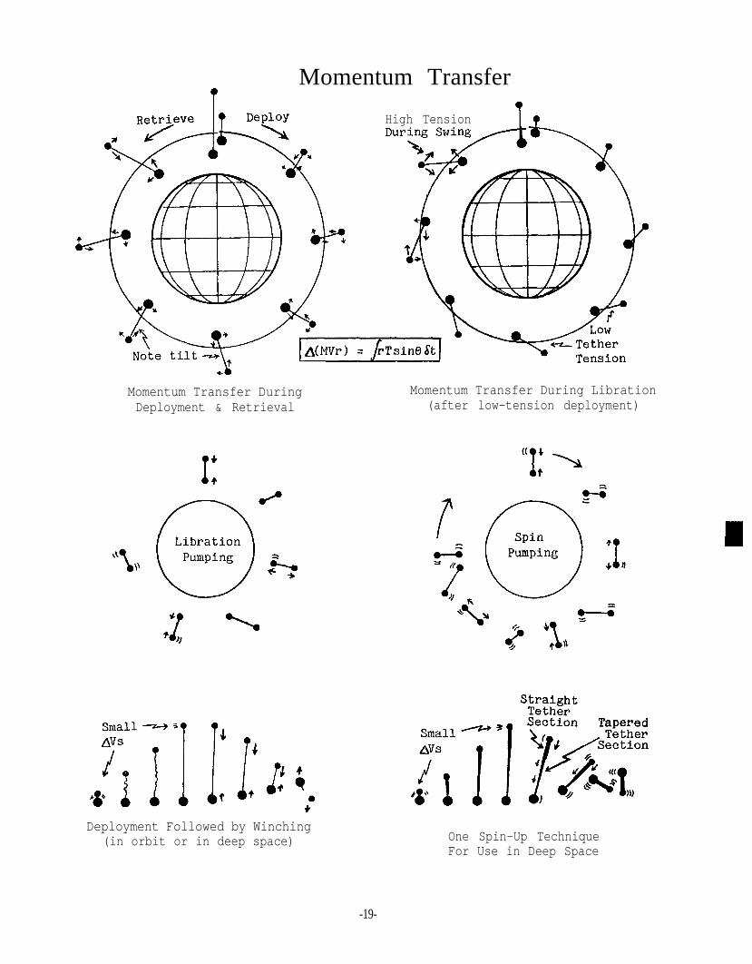
Tethers merely redistribute angular momentum; they do not create it.KEY POINTS Changes in tether length, libration, and spin all redistribute momentum.
Momentum transfer out-of-plane or in deep space is possible but awkward.
The two figures at right show two different tether deployment (and retrieval)techniques. In both cases, the initial deployment (which is not shown) isdone with RCS burns or a long boom. In the case at left, the tether is paidout under tension slightly less than the equilibrium tension level for thattether length. The tether is slightly tilted away from the vertical duringdeployment, and librates slightly after deployment is complete.
In the other case, after the initial near-vertical separation (to about 2% ofthe full tether length), the two end masses are allowed to drift apart in near-free-fall, with very low but controlled tension on the tether. Just under oneorbit later, the tether is almost all deployed and the range rate decreases toa minimum (due to orbital mechanics). RCS burns or tether braking are used tocushion the end of deployment and prevent end mass recoil. Then the tethersystem begins a large-amplitude prograde swing towards the vertical.
NOTES
In both cases, the angular momentum transferred from one mass to the other issimply, as stated in the box, the integral over time of the radius times thehorizontal component of tether tension. In one case, transfer occurs mainlyduring deployment; in the other, mainly during the libration after deployment.In each case, momentum transfer is greatest when the tether is vertical, sincethe horizontal component of tether tension changes sign then.
An intermediate strategy-deployment under moderate tension-has also beeninvestigated.’ However, this technique results in very high deploymentvelocities and large rotating masses. It also requires powerful brakes anda more massive tether than required with the other two techniques.
As discussed under Tether Control Strategies, changing a tether’s length inresonance with variations in tether tension allows pumping or damping of libra-tion or even spin. Due to Coriolis forces, in-plane libration and spin causefar larger tension variations than out-of-plane libration or spin, so in-planebehavior is far easier to adjust than out-of-plane behavior. Neglecting anyparasitic losses in tether hysteresis & the reel motor, the net energy neededto induce a given libration or spin is simply the system’s spin kinetic energyrelative to the local vertical, when the system passes through the vertical.
Two momentum transfer techniques which appear applicable for in-plane, out-of-plane, or deep-space use are shown at right. The winching operation can uselighter tethers than other tethered-momentum-transfer techniques, but requiresa very powerful deployer motor. The tangential AV simply prevents a collision.
The spin-up operation (proposed by Harris Mayer) is similar to the winchingoperation. It uses a larger tangential AV, a tether with straight and taperedsections, and a small motor. Retrieval speeds up the spin by a factor of L-2.Surprisingly, the long tapered section of tether can be less than half asmassive as the short straight section that remains deployed after spin-up.
REFERENCE 1. J. Tschirgi, “Tether-Deployed SSUS-A, report on NASA Contract NAS8-32842,McDonnell Douglas, April 1984.
-18-
Momentum Transfer?
High Tension
Momentum Transfer During Momentum Transfer During LibrationDeployment & Retrieval (after low-tension deployment)
Deployment Followed by Winching(in orbit or in deep space) One Spin-Up Technique
For Use in Deep Space
-19-

The achievable orbit change scales with the tether length (as long as Ar<< r).
KEY POINTS Retrograde-libration releases are inefficient, but allow concentric orbits.Apogee & perigee boosts have different values in different applications.Tethered capture can be seen as a time-reversal of a tether release operation
The figures to the right show the size of the orbit changes caused by varioustether operations. When released from a vertical tether, the end masses areobviously one tether length apart in altitude. The altitude difference l/2orbit later, Am, varies with the operation but is usually far larger. Thelinear relationship shown becomes inaccurate when s approaches r. Tetheredplane changes are generally limited to a few degrees and are not covered here.
Tether release leaves the center-of-mass radius at each phase angle roughlyunchanged: if the upper mass is heavier, then it will rise less than the lowermass falls, and vice-versa. Note that the libration amplitude, emax, is takenas positive during prograde libration & negative during retrograde libration.Hence retrograde libration results in or < 7L. In particular, the pre-release& post-release orbits will all be concentric if 6max = -60’. But sincemethods of causing -60’ librations usually involve +60° librations (whichallow much larger boosts by the same tether), prograde releases may usually bepreferable unless concentric orbits are needed or other constraints enter in.
NOTESThe relative tether length, mass, peak tension, and energy absorbed by thedeployer brake during deployment as a function of (prograde) libration angleare all shown in the plot at right. Libration has a large effect on brakeenergy. This may be important when retrieval of a long tether is required,after release of a payload or after tethered-capture of a free-flying payload.
The double boost-to-escape operation at right was proposed by A. Cutler. Itis shown simply as an example that even though momentum transfer is strictly a“zero sum game”, a tethered release operation can be a “WIN-win game” (a largewin & a small one). The small win on the deboost-end of the tether is due tothe reduced gravity losses l/2 orbit after release, which more than compensatefor the deboost itself. Another example is that deboosting the shuttle from aspace station can reduce both STS-deboost & station-reboost requirements.
Rendezvous of a spacecraft with the end of a tether may appear ambitious, butwith precise relative-navigation data from GPS (the Global Positioning System)it may not be difficult. The relative trajectories required are simply a time-reversal of relative trajectories that occur after tether release. Approach toa hanging-tether rendezvous is shown at right. Prompt capture is needed withthis technique: if capture is not achieved within a few minutes, one shouldshift to normal free-fall techniques. Tethered capture has large benefits insafety (remoteness) and operations (no plume impingement; large fuel savings).The main hazard is collision, due to undetected navigation or tether failure.
2.REFERENCES
3.
4.
G. Colombo, “Orbital Transfer & Release of Tethered Payloads,” SAO reporton NASA Contract NASS-33691, March 1983.W.D. Kelly, “Delivery and Disposal of a Space Shuttle External Tank to LowEarth Orbit,” J. of the Astronaut. Sci., Vol. 32, NO. 3, July-Sept 1984.J.A. Carroll, “Tether-Mediated Rendezvous,” report to Martin Marietta onTask 3 of contract RH3-393855, March 1984.J.A. Carroll, “Tether Applications in Space Transportation”, IAF 84-438, atthe 35th IAF Congress, Ott 1984. To be published in ACTA ASTRONAUTICA.
-2o-

Orbit Transfer by Tethered Release or Capture
Effects of Tether Deployment and Release
RelTension/Length
Length*MaxTension
O-50/ %kTety 0~ l/(1+.866 Sinemax)
~:~~~t -?
Lot ( L e n g t h * Cos&nax)'0
; .'@r% ,30" 90"Amplitude
Effects of Libration(for equal-m boosts)
Trajectory for Tethered Capture from Above(in tether-centered LV-LH reference frame)
* (7 + J48 Sinemax)
Effect of Libration on Boost(release at middle of swing)
*._
If done right, a tetherboost/deboost operationcan reduce AV-to-escapefor both end masses!
STS hovers OMV "chases"till captured passive targetE

Tether operations cause higher-order repartitions of energy & angular momentum.KEY POINTS First-order approximations that neglect these effects may cause large errors.
Extremely long systems have strange properties such as positive orbital energy.
The question and answer at right are deceptively simple. The extent to whichthis is so, and the bizarre effects which occur in extreme cases, can be seenin the 3 graphs at right. At top, deploying & retrieving two masses on a verylong massless tether changes not only the top & bottom orbital radii but alsothat of the CM. In addition, the free-fall location drops below the CM. Otherkey parameter changes under the same conditions are plotted underneath.
Note that when the tether length exceeds about 30% of the original orbitalradius, the entire system lies below the original altitude. Also, at a radiusratio near 1.95:1, the maximum tether length compatible with a circular orbitis reached. At greater lengths (and the initial amount of angular momentum),no circular orbit is possible at any altitude.
NOTES
Tether retrieval at the maximum-length point can cause the system to eitherrise or drop, depending on the system state at that time. If it continues todrop, there is a rapid rise in tether tension, and the total work done by thedeployer quickly becomes positive. This energy input eventually becomes largeenough (at 2.89:1) to even make the total system energy positive. The systemis unstable beyond this point: any small disturbance will grow and can causethe tether system to escape from the body it was orbiting. (See ref. 2.)
The case shown is rather extreme: except for orbits around small bodies suchas asteroids, tethers either will be far shorter than the orbital radius, orwill greatly outweigh the end masses. Either change greatly reduces the sizeof the effects shown. The effects on arbitrary structures can be calculatedusing the equations listed at right, which are based on a generalization ofthe concept of “moments” of the vertical mass distribution. Changes in tetherlength or mass distribution leave h unchanged, so other parameters (includingrem, n, and E) must change. (For short tethers, the changes scale roughlywith the square of the system’s radius of gyration.) In many cases differentconditions are most easily compared by first finding the orbital radius thatthe system would have if its length were reduced to 0, rLtzO’
The mechanism that repartitions energy and angular momentum is that lengthchanges cause temporary system displacements from the vertical. This causesboth torques and net tangential forces on the system, which can be seen bycalculating the exact net forces and couples for a non-vertical dumbbell.The same effect occurs on a periodic basis with librating dumbbells, causingthe orbital trajectory to depart slightly from an elliptical shape.
Other topics which are beyond the scope of this guidebook but whose existenceshould be noted are: eccentricity changes due to deployment, orbit changes dueto resonant spin/orbit coupling, and effects of 2- & 3-dimensional structures.
1. G. Colombo, M. Grossi, D. Arnold, & M. Martinez-Sanchez, “Orbital Transfer
REFERENCESand Release of Tethered Payloads,” continuation of NAS8-33691, final reportfor the period Sept 1979-Feb 1983, Smithsonian Astrophysical Observatory,March 1983. (in particular, see the table on page 21)
2. D. Arnold, “Study of an Orbiting Tethered Dumbbell System Having PositiveOrbital Energy,” addendum to final report on NAS8-35497, SAO, Feb 1985.
-22-
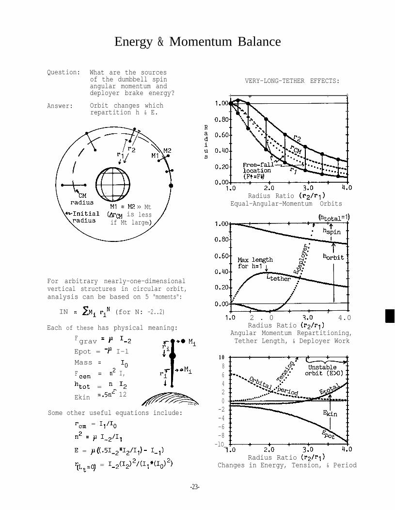
Question: What are the sourcesof the dumbbell spinangular momentum anddeployer brake energy?
Answer: Orbit changes whichrepartition h & E.
>> Mtless /(Arm is
if Mt large)/
For arbitrary nearly-one-dimensionalvertical structures in circular orbit,analysis can be based on 5 "moments":
IN = r:Mi riN (for N: -2..2)
Each of these has physical meaning:
Fgrav = p I-2
Epot = -r I-l
Mass = IOF ten = n2 I,
htot = n-12
Ekin =.5nL 12
Some other useful equations include:
r = I,/10
n'"= p I_2/I,
E = p((.51_2*12/I,)- I_,)
?L -0) = I_2u2~2/(I,*uo~2)t-
VERY-LONG-TETHER EFFECTS:
+ T +
Energy & Momentum Balance
Radius Ratio (r2/rl)Equal-Angular-Momentum Orbits
ll0 2 . 0 7.0 . 4.0Radius Ratio (r2/rl)
Angular Momentum Repartitioning,Tether Length, & Deployer Work
1086420
-2-4-6-8
-lO_
Radius Ratio (r2/rl)Changes in Energy, Tension, & Period
-23-

KEY POINTSTether strength/weight ratio constrains performance in ambitious operations.Required tether mass is easily derivable from deltaV and payload mass.
Usable specific strength can be expressed in various ways. Three ways are shownat right. Vc, Lc, and Llg are here defined in terms of a typical design stress(new/ma) rather than the (higher) ultimate stress. Including the safety factorhere streamlines the subsequent performance calculations. Higher safety factorsw needed with non-metals than with metals since non-metals are often more var-iable in their properties, brittle, abrasion-sensitive, and/or creep-sensitive.A safety factor of 4 (based on short-term fiber strength) is typical for Kevlar,but the most appropriate safety factor will vary with the application.
The “characteristic velocity,” Vc, is the most useful parameter in tether-boost calculations, because the tether mass can be calculated directly fromaV/Vc, independently of the orbit, and nearly independently of the operation.The table at the bottom, which lists tether/rocket combinations that have thelowest life-cycle mass requirements, holds whenever kVc=l km/sec & Isp =350 sec.
NOTES
The characteristic length Lc is useful in hanging-tether calculations. It varieswith the orbital rate n. (The simple calculation given assumes L<<r; if thisis not true, l/r effects enter in, and calculations such as those used in refs3-5 must be used.) The safe l-gee length Llg is mainly useful in terrestrialapplications, but is included since specific strength is often quoted this way.(Note that Vc and Lc vary with Sqrt(strength), and Llg directly with strength.)
The specific modulus is of interest because it determines the speed of soundin the tether (C=the speed of longitudinal waves), the strain under design loadm/L= {VC&}~), & the recoil speed after failure under design load (= Vc%).
Tether mass calculations are best done by considering each end of the tetherseparately. If Mpl>>MpP, then Mtl can be neglected in preliminary calculations.
Du Pont’s Kevlar is the highest-specific-strength fiber commercially available.Current R&D efforts on high-performanceexhibit nearly twice the strength of Kevlar.’
polymers indicate that polyester canTwo fiber producers have already
announced plans to produce polymers with twice the specific strength of Kevlar.
In the long run, the potential may be greater with inorganic fibers like Sic& graphite. Refs. 3-5 focus on the requirements of “space elevators.” Theydiscuss laboratory tests of single-crystal fibers and suggest that lo-foldimprovements in specific strength (or 3-fold in Vc & Lc) are conceivable.
1. Characteristics and Uses of Kevlar 49 Aramid High Modulus Organic Fiber.available from Du Pont’s Textile Fibers Department, 1978.
2. G Graff, “Superstrong Plastics Challenge Metals,” High Technology magazine,February 1985, pp. 62-63.
REFERENCES 3. J. Isaacs, H. Bradner, G.Backus, and A.Vine, “Satellite Elongation into aTrue .“Skyhook”;; a letter to Science, Vol. 151, pp. 682-683, Feb 11, 1966.
4. J. Pearson, “The Orbital Tower: a Spacecraft Launcher Using the Earth’sRotational Energy,” Acta Astronautica, Vo1.2, pp. 785-799, Pergamon, 1975.
5. H. Moravec, “A Non-Synchronous Orbital Skyhook,” J. of the AstronauticalSciences, Vol. XXV, No. 4, pp. 307-322, Oct-Dec 1977.
-24-

Specific Strength and Required Tether Mass
SPECIFIC STRENGTH __) commercialc= 20 km/s 1 1 o=
I I @ = potential
* Design stress is assumed to be l/2 the ultimate strength for metalsand l/4 the short-term individual fiber strength for other materials.
SPECIFIC STRENGTH & MODULUS OF SEVERAL TETHER MATERIALS
Gaussian "normally
Ll<LcL2>Lc
Mt 1 <l Mp 1Mt2>Mp2
Tether Length & Required Mass
/
I/I\ \
0.00 0.50 1.00 1.50 2.00
X (= DV/kVc, or L/Lc) *Required Tether Mass (Mt)
= Sum of perigee + apogee boosts
IBest tether DV, km/s 1 .14 .9 I.8 I 2.6 1
Required Mt/Mp .02 1 1 11 1 95 1
(For kVc = 1 km/s and rocket Isp = 350 seconds;marginal deployer & dry rocket masses neglected.)
Best Tether DV for Combined Tether/Rocket Boosts\ /. /--A
-25-
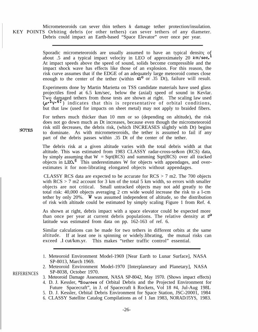
Micrometeoroids can sever thin tethers & damage tether protection/insulation.KEY POINTS Orbiting debris (or other tethers) can sever tethers of any diameter.
Debris could impact an Earth-based “Space Elevator” over once per year.
Sporadic micrometeoroids are usually assumed to have an typical density ofabout .5 and a typical impact velocity in LEO of approximately 20 km/sec.lAt impact speeds above the speed of sound, solids become compressible and theimpact shock wave has effects like those of an explosion. For this reason, therisk curve assumes that if the EDGE of an adequately large meteoroid comes closeenough to the center of the tether (within 45’ or .35 Dt), failure will result.
Experiments done by Martin Marietta on TSS candidate materials have used glassprojectiles fired at 6.5 km/sec, below the (axial) speed of sound in Kevlar.Two damaged tethers from those tests are shown at right.(,o.5V.67
The scaling law used) indicates that this is representative of orbital conditions,
but that law (used for impacts on sheet metal) may not apply to braided fibers.
NOTES
For tethers much thicker than 10 mm or so (depending on altitude), the riskdoes not go down much as Dt increases, because even though the micrometeoroidrisk still decreases, the debris risk, (which INCREASES slightly with Dt) beginsto dominate. As with micrometeoroids, the tether is assumed to fail if anypart of the debris passes within .35 Dt of the center of the tether.
The debris risk at a given altitude varies with the total debris width at thataltitude. This was estimated from 1983 CLASSY radar-cross-se&on (RCS) data,by simply assuming that Wobjects in LE0.6
= Sqrt(RCS) and summing Sqrt(RCS) over all trackedThis underestimates W for objects with appendages, and over-
estimates it for non-librating elongated objects without appendages.
CLASSY RCS data are expected to be accurate for RCS > 7 m2. The 700 objectswith RCS > 7 m2 account for 3 km of the total 5 km width, so errors with smallerobjects are not critical. Small untracked objects may not add greatly to thetotal risk: 40,000 objects averaging 2 cm wide would increase the risk to a l-cmtether by only 20%. w was assumed independent of altitude, so the distributionof risk with altitude could be estimated by simply scaling Figure 1 from Ref. 4.
As shown at right, debris impact with a space elevator could be expected morethan once per year at current debris populations. The relative density at 0’latitude was estimated from data on pp. 162-163 of ref. 6.
Similar calculations can be made for two tethers in different orbits at the samealtitude. If at least one is spinning or widely.librating, the mutual risks canexceed .l cut/km.yr. This makes “tether traffic control” essential.
1.
2.REFERENCES
3.4.
5.6.
Meteoroid Environment Model-1969 [Near Earth to Lunar Surface], NASASP-8013, March 1969.Meteoroid Environment Model-1970 [Interplanetary and Planetary], NASASP-8038, October 1970.
Meteoroid Damage Assessment, NASA SP-8042, May 1970. (Shows impact effects)D. J. Kessler, nSources of Orbital Debris and the Projected Environment forFuture Spacecraft”, in J. of Spacecraft & Rockets, Vol 18 #4, Jul-Aug 198LD. J. Kessler, Orbital Debris Environment for Space Station, JSC-20001, 1984CLASSY Satellite Catalog Compilations as of 1 Jan 1983, NORAD/J5YS, 1983.
-26-

Impact Hazards for Tethers
Braided StainlessKevlar, steel wire,grazed direct hit
Effective Width, W(Any position betweenthe 2 extremes showncuts the tether.)
1O-2 I 1 I I I I ,
Assumptions: zw+=355
cutsKmoYrin 1LEO
0.20 mm .25 mm .30 mm 935Max non-fatal pm diameter Dm
PMeteoroid Risks to a 1 mm Tether
10-3
cuts lf4Km l Yr
1O-5lj;;;-6 'Risk varies with i by a factor of <2
10 L * 1 I I , I0 1000 2000 3000 4000
Altitude, kmDebris Impact Rate on Tethers in LEO
For tethers with Dt > 1 (mm),& Max non-fatal Dm = .25 Dt,
pm cuts m Dt-2.6KmaYr
Debris Risk to the Lowest 4000 kmof an Earth-based Space Elevator:
Risk =ZWidth * 'ii * RelDensity at X=oEarth "Surface Area" at m
-5 km * ~7.3 km/see * ~.72=4 * pi * Sqr(-7378 km)
s 3.9E-8/set =vcuts/year(
-27-

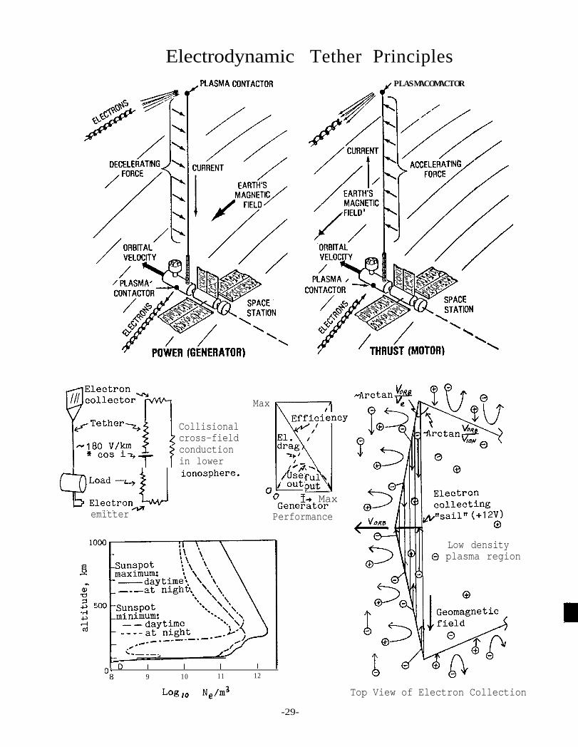
KN POINTSTether (& other) resistance can limit the output of electrodynamic tethers.Electron collection methods & effectiveness are important-and uncertain.
Since the publication of ref. 1, 20 years ago, electrodynamic tether proposalsand concepts have been a frequent source of controversy, mainly in these areas:
1. What plasma instabilities can be excited by the current?2. What is the current capacity of the plasma return loop?3. What is the best way to collect electrons from the plasma?
The first Tethered Satellite mission may do much to answer these questions.The discussion below and graphics at right merely seek to introduce them.
The current flowing through an electrodynamic tether is returned in thesurrounding plasma. This involves electron emission, conduction along thegeomagnetic field lines down to the lower ionosphere, cross-field conductionby collision with neutral atoms, and return along other field lines.
NOTES
The tether current causes a force on the tether (and on the field) perpendicu-lar to both the field and the tether (horizontal, if the tether is vertical).Motion of the tether through the geomagnetic field causes an EMF in the tether.This allows the tether to act as a generator, motor, or self-powered ultra-low-frequency broadcast antenna.2 The motion also causes each region of plasmato experience only a short pulse of current, much as in a commutated motor.
Based on experience with charge neutralization of spacecraft in high orbit,it has been proposed that electrons be collected by emitting a neutral plasmafrom the end of the tether, to allow local cross-field conduction.3 InGEO, the geomagnetic field traps a plasma in the vicinity of the spacecraft,and “escape” along field lines may not affect its utility. This may also holdin high-inclination orbits in LEO. But in low inclinations in LEO, any emittedplasma might be promptly wiped away by the rapid motion across field lines.
A passive collector such as a balloon has high aerodynamic drag, but a end-onsail can have an order of magnitude less drag. The electron-collection5 sketchat bottom right is based on a preliminary analysis by W. Thompson. Thisanalysis suggests that a current moderately higher than the electron thermalcurrent (=Ne * m200 km/set) might be collected on a surface normal to the field.This is because collecting electrons requires that most ions be reflected awayfrom the collection region as it moves forward. This pre-heats and densifiesthe plasma ahead of the collector. The voltage required for collection is justthe voltage needed to repel most of the ions, about 12 V.
1.
2.
REFERENCES 3.
4.
5.
S.D. Drell, H.M. Foley, & M.A. Ruderman, “Drag and Propulsion of LargeSatellites in the Ionosphere: An Alfven Propulsion Engine in Space,” J.of Geophys. Res., Vol. 70, No. 13, pp. 3131-3145, July 1965.M. Grossi, “A ULF Dipole Antenna on a Spaceborne Platform of the PPEPLClass,” Report on NASA Contract NASS-28203, May 1973.RA Moore, “The Geomagnetic Thruster-A High Performance “Alfven Wave”Propulsion System Utilizing Plasma Contacts,” AIAA Paper No. 66-257.ST. Wu, ed., University of Alabama at Huntsville/NASA Workshop on The Usesof a Tethered Satellite System, Summary Papers, Huntsville AL, May 1978.See papers by M. Grossi et al, R. Williamson et al., and N. Stone.W. Thompson, “Electrodynamic Properties of a Conducting Tether,” FinalReport to Martin Marietta Corp. on Task 4 of Contract RH3-393855, Dec. 1983.
-28-
Electrodynamic Tether Principles/PLAShlACONTACTOR
Max
Collisionalcross-fieldconductionin lower
PLASMACOMACTOR
-41
:p-/&efulu/ outputQ:::::_U ionosphere-
emitterJGener ator
I+ Max
Performance
L-B_-.,
n. D I I I I
v8 9 10 11 12
Log IO Ne/m3
Low density0 plasma region
Top View of Electron Collection
-29-
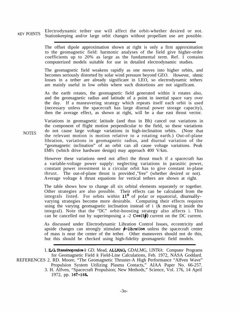
KEY POINTSElectrodynamic tether use will affect the orbit-whether desired or not.Stationkeeping and/or large orbit changes without propellant use are possible.
The offset dipole approximation shown at right is only a first approximationto the geomagnetic field: harmonic analyses of the field give higher-ordercoefficients up to 20% as large as the fundamental term. Ref. 1 containscomputerized models suitable for use in detailed electrodynamic studies.
The geomagnetic field weakens rapidly as one moves into higher orbits, andbecomes seriously distorted by solar wind pressure beyond GEO. However, ohmiclosses in a tether are already significant in LEO, so electrodynamic tethersare mainly useful in low orbits where such distortions are not significant.
As the earth rotates, the geomagnetic field generated within it rotates also,and the geomagnetic radius and latitude of a point in inertial space vary overthe day. If a maneuvering strategy which repeats itself each orbit is used(necessary unless the spacecraft has large diurnal power storage capacity),then the average effect, as shown at right, will be a due east thrust vector.
Variations in geomagnetic latitude (and thus in Bh) cancel out variations inthe component of flight motion perpendicular to the field, so these variations
NOTES do not cause large voltage variations in high-inclination orbits. (Note thatthe relevant motion is motion relative to a rotating earth.) Out-of-planelibration, variations in geomagnetic radius, and diurnal variation of the“geomagnetic inclination” of an orbit can all cause voltage variations. PeakEMFs (which drive hardware design) may approach 400 V/km.
However these variations need not affect the thrust much if a spacecraft hasa variable-voltage power supply: neglecting variations in parasitic power,constant power investment in a circular orbit has to give constant in-planethrust. The out-of-plane thrust is provided ,"free" (whether desired or not).Average voltage & thrust equations for vertical tethers are shown at right.
The table shows how to change all six orbital elements separately or together.Other strategies are also possible. Their effects can be calculated from theintegrals listed. For orbits within 11’ of polar or equatorial, diurnally-varying strategies become more desirable. Computing their effects requiresusing the varying geomagnetic inclination instead of i (& moving it inside theintegral). Note that the “DC” orbit-boosting strategy also affects i. Thiscan be cancelled out by superimposing a -2 Cos(2j) current on the DC current.
As discussed under Electrodynamic Libration Control Issues, eccentricity andapside changes can strongly stimulate $-libration unless the spacecraft centerof mass is near the center of the tether. Other maneuvers should not do this,but this should be checked using high-fidelity geomagnetic field models.
L EG Stassinopoulce & GD. Mead, ALIMAG, GDALMG, LINTRA: Computer Programsfor Geomagnetic Field & Field-Line Calculations, Feb. 1972, NASA Goddard.
REFERENCES 2. RD. Moore, “The Geomagnetic Thruster-A High Performance “Alfven Wave”Propulsion System Utilizing Plasma Contacts,” AIAA Paper No. 66-257.
3. H. Alfven, “Spacecraft Propulsion; New Methods,” Science, Vol. 176, 14 April1972, pp. 167-166.
-3o-

Electrodynamic Orbit Changes
OFFSET DIPOLE APPROXIMATION TO GEOMAGNETIC
Orbital
/JFIELD
I+-EARTH'SSPIN AXIS
GEOMAGNETIC
VECTOR IS
EFFECT OF EARTH'S SPINON TIME-AVERAGED FIELD
HOWTO CHANGEORBITS USING AN ELECTROOYNAMICTETHER
Element
Semlmajor axls
Strategy Thrust Vector Effect
~=POSlTlONOF VEHICLE WITHREFERENCE TO ITS PERtGEE
+ POSI-TION WITH REFERENCETO ASCENDING NODE
k= -4TONNES PER AMPERE
m= TOTAL VEHICLE Miss
n = ORBITAL ANGULAR RATE
-31-

Properly controlled AC components can be used to control 6 and #-libration.KEY POINTS Solar-energy storage and e or u) changes strongly stimulate $-libration.
AC currents other than 1 & 3/orbit should not affect #-libration much.
The maneuvering strategies on the previous page have assumed that electrodyn-amic tethers will stay vertical. However, as shown at right, the distributedforce on the tether causes bowing, and that bowing is what allows net momentumtransfer to the attached masses. Note that net momentum can be transferred tothe system even if the wire is bowed the wrong way (as when the current is sud-denly reversed); momentum transferred to the wire gets to the masses later.
This figure also illustrates two other issues:l. Bowing of the tether causes it to cross fewer field lines.2. Unequal end masses and uniform forces cause overall torques & tilting.
The bowing causes the tether to provide less thrust while dissipating the sameparasitic power. The net force on the system is the same as if the tetherwere straight but in a slightly weaker magnetic field.
The torque on the system causes it to tilt away from the vertical, until thetorque is balanced by gravity-gradient restoring torques. For a given systemmass and power input, disturbing torques vary with L and restoring torques
NOTES with L2 , so longer systems can tolerate higher power. The mass distributionalso affects power-handling capability, as seen in the sequence at top right.
Modulating the tether current modulates any electrodynamic torques. Currentmodulation at L73 n can be used to control in-plane libration. Out-of-planetorques can also be modulated, but another control logic is required. This isbecause the once-per-orbit variation in out-of-plane thrust direction makes acurrent with frequency F (in cycles per orbit) cause out-of-plane forces andtorques with frequencies of F-l and F+l, as shown in the Fourier analysis atbottom right. Hence $ libration control (F =2) requires properly phased F =l orF =3 currents. Higher frequencies can damp odd harmonics of any tether bowingoscillations. Control of both in- & out-of-plane oscillations may be possiblesince they have the same frequencies and thus require different currents.
Applications that require significant F=l components for other reasons cancause problems. Four such strategies are shown at right. Sin & Cos controlsallow adjustment of e or w. The two “Sign of . ..” laws allow constant powerstorage over 2/3 of each orbit and recovery the rest of the orbit. These lawswould be useful for storing photovoltaic output for use during dark periods.
These strategies drive out-of-plane libration (unless the center of mass is atthe center of the tether). The libration frequency decreases at large ampli-tudes, so if the system is not driven too strongly, it should settle into afinite-but-large-amplitude phase-locked loop. This may be unacceptable insome applications, due to resulting variations in gravity or tether EMF. Insome cases, such as eccentricity changes, adding a F = 3 component might cancelthe undesired effect of an F =l current while keeping the desired effect.
L G. Colombo, M. Grossi, M. Dobrowolny, and D. Arnold, Investigation of Elec-REFERENCE trodynamic Stabilization & Control of Long Orbiting Tethers, Interim Report
on Contract NAS8-33691, March 1981, Smithsonian Astrophysical Observatory.
-32-

Electrodynamic Libration Control Issues
i\
INCREASING STABILITY A(for fixed total length & mass & I)
FOR CONTROL OF: MODULATE I AT:
Out-of-plane libration* l n or 3 n
In-plane librations* 1.73 n
Tether oscillations >5 n
* I or mass distribution must be lopsided
Tether Current:
I = 1.0
I = Sin $
I = cos #
L,
I = Sign of(.5+Sin@ >
I = Sign of(.5+Cosrn,
I =: Sin 2dj
II = cos 23
Fourier Analysis ofOut-Of-Plane Forces:
ln 2n 3n
.50 0 0
.50
.03
.50 0 .50
.50 0 .50- I - - - - + - - - -0 90 180 270 + drives # librationDeg Past Ascending Node,4
-33-

BIBLIOGRAPHY OF SPACE-TETHER LITERATURE
The number of references listed with each topic in the body of the Guidebookwas intentionally limited. A more comprehensive bibliography follows. It wascompiled by merging bibliographies previously compiled by Mark Henley, PeterSwan, Georg von Tiesenhausen, and others. It will be expanded and updated infuture revisions of the Guidebook.
Many references (particularly final reports) cover several topics. However theyare listed here only under the most specific relevant heading. For example,transport concepts explicitly intended for use on a space station are listedunder space stations. For thoroughness, check related headings.
BIBLIOGRAPHY HEADINGS:
GeneralThe Tethered Satellite SystemSpace Station & Constellation ApplicationsTransportationElectrodynamicsDynamics, Controls, & Simulations (incl. TSS)Beanstalks and Other Ambitious ConceptsTether Materials
SOME FREQUENTLY OCCURRING ABBREVIATIONS:
CSI = California Space Institute, SIO/UCSD, La Jolla CAIAF = International Astronautical FederationJSC = Johnson Space Center, Houston TXMSFC = Marshall Space Flight Center, Huntsville ALSAO = Smithsonian Astrophysical Observatory, Cambridge, MA
GENERAL
-, Applications of Tethers in Space, Vol. 1 & 2, Workshop Proceedings,15-17 June 1983.
-, Proposed 1984-1987 Program Plan for Tether Applications in Space,prepared by NASA Tether Applications in Space Task Group, Sept 1983.
-, Selected Tether Applications in Space-An Analysis of 5 Selected Concepts,July 31, 1984, Martin Marietta final report, NASA Contract NAS 8-35499.
-, Selected Tether Applications in Space-Phase II, Preliminary Draft ofFinal Report on NASA Contract NAS 8-35499, Martin Marietta, February 1985.
-, Movies for Gemini Missions XI and XII, available from Public AffairsOffice, AP2, NASA JSC, Houston TX 77058. (See tether-experiment sequences.)
Bekey, Ivan, Tethers Open New Space Options, Astronautics & Aeronautics, April1983. Reprint available from OSF, MT-3, NASA Headquarters, Wash. D.C. 20546.
-34-

Carroll, J., Some Tether-Related Research ‘Pop&, prepared under JPL contractLC 778278 for the NASA Tether Applications in Space Task Force, November 1984.
Lang, D.D., and R.K. Nolting, “Operations with Tethered Space Vehicles,” inProceedings of the Gemini Summary Conference, NASA SP-138, 1967.
Laue, J., U.S./Italian Discussion on Tether-Related Activities at NASAHeadquarters, NASA/MSFC, Nov.18, 1982.
Von Tiesenhausen, G., Tethers in Space-Birth and Growth of a New Avenue toSpace Utilization, Feb. 1984. NASA-TM-82571, NASA/MSFC.
THE TETHERED SATELLITE SYSTEM
-, Shuttle Tethered Satellite System Design Study, NASA TM X-73365, MSFC,1976.
-, Shuttle Tethered Satellite System Definition - Final Study Report, NAS8-32854, Martin Marietta Aerospace, April 1979.
-, Shuttle Tethered Satellite System Definition - Final Study Report, NAS8-32853, Ball Aerospace Systems Division, April 1979.
-, Shuttle Tethered Satellite System, Final Report from the Facility Require-ments Definition Team; sponsored by MSFC under NASA Contract NAS8-33383 to theCenter for Atmospheric and Space Sciences, Utah State Univ., May 1980.
-, TSS Final Review, Martin Marietta presentation at MSFC, Dec 14-15, 1982.
Arnold, D., G. Colombo, N. Hanham, and G. Nystom, System Noise Analysis of theDumbbell Tethered Satellite for Gravity-Gradient Measurements, final report onNASA grant NSG-8063, 1979.
Baker, W., J.A. Dunkin, Z.J. Galaboff, K.D. Johnson, RR Kissel, M.H. Rhein-furth and M.P.L. Siebel, Tethered Subsatellite Study, NASA TM X-73314, MSFC,March 1976.
Colombo, G., EM. Gaposchkin, M.D. Grossi, and G.C. Weiffenbach, “The Skyhook”:A Shuttle-Borne Tool for Low Orbital Altitude Research”, MECCANICA, March 1975.
Colombo, G., EM. Gaposchkin, M.D. Grossi, and G.C. Weiffenbach, “Long TetheredSatellites for the Shuttle Orbiter”, p resented at the International Conferenceon Technology of Scientific Space Experiments, Paris, Fance, May 1975.
Colombo, G., E.M. Gaposchkin, M.D. Grossi, and G.C. Weiffenbach, “Shuttle-borneLong-tethered Satellites, A New Tool for Low Cost Space Science & Applications”,presented at AAS/AIAA Conference, Nassau, Bahamas, July 1975.
Colombo, G., D. Arnold, J. Binsack, R. Gay, M. Grossi, D. Lautman, and 0. Orrin-ger, Dumbbell Gravity-Gradient Sensor: A New Application of Long Tethers, SAOReports in Geoastronomy, no. 2, 1976.
Colombo, G., E. Gaposchkin, M. Grossi, and G. Weiffenbach, Gravity-Gradient Mea-surements down to 100 km Height by Means of Long Tethered Satellites, presentedat 27th IAF Congress, Anaheim CA, Oct 1977.
-35-

G. Colombo, D. Arnold, E. Gaposchkin, M. Grossi, P. Kalaghan, and L. Kirschner,Tethered Satellite System for Gravity Gradiometry at Low Orbital Height,presented at the Earth Dynamics Summer Workshop, Boulder CO, July 197’7.
Colombo, G., et al., “Satellite Connected by Means of a Long Tether to aPowered Spacecraft, ” US Patent 4,097,OlO. June 27, 1978.
Colombo, G., S. Bergamaschi, and F. Bevilacqua, “The Italian Participationto the Tethered Satellite System" , IAF#81-33, 32nd IAF Congress, Sept 1981.
Crouch, Donald S., “Shuttle Tethered Satellite System Program Overview”,Applications of Tethers in Space Workshop, Williamsburg, Va., June 15, 1983.
Laue, Jay H., “Tethered Satellite System-Project Overview”, Briefing givenNASA/MSFC/PF17, Jan 19, 1983.
Laue, J.H. and F. Manarini, “The Tethered Retrievable Platform Concept andUtilization”, IAF-82-13, 33rd IAF Congress, Sept-Ott 1982, Paris France.
Lundquist, C., and G. Colombo, “Advanced Technologies in Space and Opportunitiesfor Gravity Experiments”, p resented at the International School of RelativisticAstrophysics, Trapani, Italy, Fall 19’77.
Manarini, G. and F. Mariani, “The Tethered Satellite System Technical Aspectsand Prospective Science Missions”, Riena, Atti 22 Convegno Intele SulloSpazio, Roma 1982.
Mariani, F., “Science by Tethered Satellite”, Dipartimento di Fisica,Universita di Roma “La Sapienza", Piazzale Aldo Moro, 2-00185, Roma, Italy.
Merlina, P., Double Tethered Satellite System, Nov. 23, 1982, Aeritalia-Settore Spazio.
Rupp, C.C. and J.H. Laue, “Shuttle/Tethered Satellite System”, Journal ofAstronautical Sciences, Vol. 26, No. 1, Jan 1978, p. 1-17.
Snoddy, W.C., “Scientific and Technical Applications of a Tethered SatelliteSystem,” AIAA Aerospace Sciences Meeting, New Orleans, La., Jan 15-17, 1979.
Wu, S.T., ed., University of Alabama at Huntsville/NASA Workshop on The Usesof a Tethered Satellite System, Summary Papers, Huntsville AL, May 1978.
SPACE STATION AND CONSTELLATION APPLICATIONS
-, Space Station Requirements for Tether Applications, July 26, 1984, MartinMarietta final report, NASA Contract NAS 8-35499.
Arnold, J.R., et al, The Process of Space Station Development Using ExternalTanks, Report to the Office of Technology Assessment, March 1983. CSI.
Carroll, J.A., Tether Mediated Rendezvous, report to Martin Marietta on Task 3of contract RH3-393855, March 1984, CSI.
Carroll, J.A., A Scenario for Tether Uses in a Space Station, AIAA/NASA SpaceSystems Technology Conference Paper 84-lllO-CP. Costa Mesa, June 5, 1984, CSI.

Colombo, G., A Preliminary Study of the Orbiting Platform-Tether System SpaceOperation Center, MIT Dept. of Aeronautics and Astronautics, 1980.
Colombo, G., A Straightforward Use of the Shuttle ET, presented at the Workshopon the Utilization of the External Tanks of the STS, 1982, CSI.
Colombo, G., and J. Slowey: On a New Concept for a Space Station Architecture,Appendix II of Report on the Utilization of the External Tanks of the STS,CSI, April 1983.
Colombo G., A New Tethered Dual Platform Space Station Concept, Oct, 1983,NASA Contract G 82678-3286, SAO.
English, R., Characteristics of a Tethered Space Station, NASA LeRC, Oct. 21,1983.
Hamlyn, K., et al., Tethered Orbital Refueling Study, Martin Marietta, NASAcontract NAS g-17059, Interim Report, January 1985.
Kroll, K.R., “Tethered Propellant Resupply Technique for Space Stations,”IAF-84-442, presented at the 35th IAF Congress, Lausanne Switzerland, 1984.
Lorenzini, E., Analytical Investigation of Dynamics of Tethered Constellationsin Earth Orbit, Aug. 17, 1984, NASA contract NAS 8-35497, SAO.
Mayer, H. L., “Swarms: Optimum Aggregations of Spacecraft, II AerospaceCorporation ATR-80(7734)-l, Feb. 29, 1980.
Nobles, W., Selected Tether Applications in Space, July 31, 1984, MartinMarietta final report/presentation on NASA Contract NAS 8-35499.
Penzo, P., Tether Induced Gravity for Space Station-Preliminary Assessment,JPL, March 12, 1982.
TRANSPORTATION
-, Preliminary Feasibility Study of the External Tank (ET) Deorbit by aTether System, May 24, 1983, Martin Marietta Memo 83-SES-665.
-, Tether Applications for the Inertial Upper Stage, Jan 1985, available fromG. Ryan, IUS Futures Organization, Boeing Aerospace Company.
Arnold, D.A., Orbital Pumping, NASA Contract NAS 8-35036, Aug. 24, 1984, SAO.
Bentz, D.J. Tethered Momentum Launching Systems, NASA Lewis Research Center.
Carroll, J.A., Tethers and External Tanks: Enhancing the Capabilities of theSpace Transportation System, final report to Martin Marietta Corp. on contractRH2-393673, Dec 1982.
Carroll, J.A., Tethers & External Tanks, ch. 3 of Report on the Utilization ofthe External Tanks of the STS, CSI, April 1983.
Carroll, J.A., and A.H. Cutler, “Potential Role of Tethers in Space Transporta-tion”, m-84-1448, presented at AIAA/SAE/ASME 20th Joint Propulsion Conference,Cincinnati OH, June 1984
-37-

Carroll, J.A., Tether Applications in Space Transportation, IAF Paper 84-438,35th IAF Congress, Lausanne, Switzerland, 1984. To be published in ACTAASTRONAUTIC%
Carroll, J.A., Disposable-Tether Payload Deploying System for the STS, finalreport on NASA SBIR Contract NAS 8-35843, Energy Science Labs., Inc., June 1984.
Contella, M.C., Tethered Deorbit of the External Tank, April 24, 1984, NASA JSC.
Colombo, G., Study of Certain Launching Techniques Using Long Orbiting Tethers,NASA-CR-164060, March 1981, SAO.
Colombo, G., et al., “Use of Tethers for Payload Orbital Transfer,” report onNAS8-33691, Mar 1982, SAO.
Colombo, G., Orbital Transfer and Release of Tethered Payloads, report on NASAContract NAS 8-33691, March 1983, SAO.
Hunter, M.W., “Near Earth Transportation Options and High Payoff Choices”,AIAA International Annual Meeting, Baltimore, MD, May 1982.
Hunter, M.W., “Advanced Space Transportation Options”, Lockheed, August 1982.
Martinez-Sanchez, M., The Use of Large Tethers for Payload Orbital Transfer,MIT, 1983.
Martinez-Sanchez, M., and S.A. Gavit, “Four Classes of Transportation Applica-tions Using Space Tethers-Preliminary Concept Assessments”, progress report toMartin Marietta, MIT Space Systems Laboratory, March 1984.
Stuart, D.G. and Martinez-Sanchez, M., Shuttle Tether Use for Payload Deploy-ment to Circular Orbits, MIT, Aug. 10, 1984.
Penzo, P.A. and Mayer H.L., Tethers and Asteroids for Artificial Gravity Assistin the Solar System, JPL, AIAA Paper 84-2056, Aug. 1984.
Tschirgi, J., Tether Deployed SSUS-A, McDonnell Douglas, April 1984, NASAContract NAS 8-32842.
ELECTRODYNAMICS
-, “Report of the Plasma Physics and Environmental Perturbation LaboratoryWorking Groups,” Program Development Contract, NASA TM X-64856, March 1974.
Alfven, II., “Spacecraft Propulsion; New Methods”, Science, Vol. 176, 14 April1972, pp. 167-168.
Anderson, A, D, Arnold, G. Colombo, M. Grossi, & L. Kirshner, Orbiting Tether’sElectrodynamic Interactions, final report on NAS5-25077, April 1979, SAO.
Arnold, D., and M. Dobrowolny, Transmission Line Model of the Interactionss ofa Long Metal Wire with the Ionosphere, submitted to Radio Science, 1979.
Arnold, D.A., and M.D. Grossi, Natural Damping in the Electrodynamic Tether,January 1983, SAO.
-38-

Banks, P.M., P.R. Williamson, and K.L. Oyama, “Shuttle Orbiter TetheredSubsatellite for Exploring and Tapping Space Plasmas,” Astronautics andAeronautics, February 1981.
Chu, C., and R. Gross, Alfven Waves and Induction Drag on Long CylindricalSatellites, AIAA Journal, Vol 4, pg 2209, 1966.
Colombo, G., M. Grossi, M. Dobrowolny, and D. Arnold, Investigation of Elec-trodynamic Stabilization & Control of Long Orbiting Tethers, Interim Reporton Contract NAS8-33691, March 1981, SAO. (Also, monthly progress reports#l-15 through September 1982.)
Dobrowolny, M., G. Colombo and M.D. Grossi,, “Electrodynamics of Long ConductingTethers in the Near Earth Environment,” Interim Report on NASA Contract #NAS8-31678. Jan 5, 1976, SAO.
Dobrowolny, M., G. Columbo, and M.D. Grossi, "Electrodynamics of Long Tethersin the Near-Earth Environment,” Final report on NAS 8-31678, June 1976, SAO.
Dobrowolny, M., D.A. Arnold, G. Colombo, and M. Grossi, “Mechanisms of Electro-dynamic Interactions with a Tethered Satellite System and the Ionosphere”,Reports in Radio and Geoastronomy, No. 6, August 1979.
Dobrowolny, M., Wave and Particle Phenomena Induced by an Electrodynamic Tether,SAO Special Report #388, November 1979.
Drell, S.D., H.M. Foley, & M.A. Ruderman, “Drag and Propulsion of Large Satel-lites in the Ionosphere: An Alfven Propulsion Engine in Space,” J. of Geophys.Res., Vol. 70, No. 13, pp. 3131-3145, July 1965.
Finnegan, P.M. A Preliminary Look at Using a Tethered Wire to Produce Poweron a Space Station, NASA LeRC, May 10, 1983.
Giudici,R., Electrodynamic Tether for Power or Propulsion Design Considera-tions, March 20, 1984, NASA MSFC-PD.
Grossi, M., “A ULF Dipole Antenna on a Spaceborne Platform of the PPEPL Class,Report on NASA Contract NAS8-28203, May 1973, SAO.
Grossi , M., On The Feasibility of Electric Power Generation and ElectromagneticWave Injection by Electrodynamic Tethers, Jan 1983, Tech. Note TP 83-003, SAO.
Grossi, M., Engineering Study of the Electrodynamic Tether as a SpaceborneGenerator of Electric Power, April 1984 NASA Contract NAS 8-35497, SAO.
King, R.W.P., The Thin Wire Antenna Embedded in a Magneto-ionic Plasma, 1980,Harvard University.
McCoy, J.C. Electrodynamic Tether Applications-Massive Tether Dynamics Study,General Status Review, May 3, 1984, NASA JSC-SN 3.
McCoy, J.C. Plasma Motor/Generator-Electrodynamic Tether Applications inSpace, NASA JSC-SN 3, June 13, 1984
McCoy, J.C. Plasma hlotor/Generator-Proof of Function Experiment, NASA JSC--SN 3, July 1, 1984
-39-

Moore, RD., “The Geomagnetic Thruster-A High Performance “Alfven Wave”Propulsion System Utilizing Plasma Contacts,” AIAA Paper No. 66-257.
Tang, W.Y., “Comparison of Three Kinds of Possible Power Generators as SpaceShuttle Power Extension Package,” Dec 31, 1981, SAO.
Thompson, W.B., Electrodynamics of a Conducting Tether, Final Report to MartinMarietta on task 4 of contract RH 3-393855, Dec. 1983, CSI & UCSD Physics Dept.
Weiffenbach, G.C., “A Study of the Electrodynamics of Long Conducting Tethersin the Near Earth Environment”, NAS8-31678, SAO.
Williamson, D.P., and Banks, P.M., The Tethered Balloon Current Generator: ASpace Shuttle-Tethered Subsatellite for Plasma Studies and Power Generation,final report on NOAA Contract #03-5-022-60, Jan. 16, 1976.
Williamson, P.R., P.M. Banks, and K. Oyama, “The Electrodynamic Tether, ” reporton NASA Contract NAS5-23837, 1978, Utah State University, Logan UT.
TETHER DYNAMICS, CONTROLS AND SIMULATIONS (incl. TSS)
-, Symposium on Passive Gravity Gradient Stabilization, NASA SP-107, May 1965.
-, Evaluation of Tether Dynamics and Control System Interaction, FinalReport, NASA Contract NAS 8-34667, June 30, 1983.
Arnold, D., “General Equations of Motion, " Appendix A of Investigation ofElectrodynamic Stabilization and Control of Long Orbiting Tethers, InterimReport, March 1981, SAO.
Allias, E, and S. Bergamaschi, “Dynamics of Tethered Satellites-Two Alter-native Concepts for Retrieval“, MECCANICA. June 1979, p. 103-111.
Anderson, W. W., On Lateral Cable Oscillations of Cable-Connected SpaceStations, NASA TN 5107, NASA Langley Research Center.
Bainum, P.M. and V.K . Kumar, “Optimal Control of the Shuttle-Tethered System”,ACTA ASTRONAUTICA, Vol. 7, May 80, p. 1333-1348. Presented as IAF#79-190 atthe 30th IAF Congress, Munich, Germany. Sept. 1979.
Bainum, P.M., R.E. Harkness and W. Stuiver, “Attitude Stability and Damping ofa Tethered orbiting Interferometer Satellite System”, Journal of AstronauticalSciences, Vol. XIX, No. 5, p. 364-389, Mar-Apr. 1972.
Banerjee, A.K. and T. R. Kane, “Tethered Satellite Retrieval with ThrusterAugmented Control”, AIAA/AAS Astrodynamics Conference, San Diego Calif, 1982.#AIAA 82-l-21,
Banerjee, A.K. and T.R. Kane, “Tether Deployment Dynamics”, Journal of Astro-nautical Sciences, Vol. XXX, No. 4, pp. 347-365, Oct-Dec 1982.
Beletskii, V.V. and M. Guivertz, “The Motion of an Oscillating Rod Subjected toa Gravitational Field”, Kosmitcheskie Issledovania 5, no. 6, 1967.
-4o-

Beletskii, V.V., The Motion of Celestial Bodies, Nauka, Moscow, 1971.
Beletskii, V.V., “Resonance Phenomena at Rotations of Artificial and NaturalCelestial Bodies,” COSPAR-IAU-IUI’AM Satellite Dynamics Symposium, June 1974,Sao Paulo, Brazil; Springer-Verlag, 1975.
Beletskii, V.V. and EM. Levin, “Mechanics of an Orbital Cable System”, trans-lated from Kosmicheskie Issledovaniya, Vol 18 #5, pp. 678-688, Sept-Oct, 1980.
Bergamaschi, Silvio, “Tether Motion after Failure”, Journal of AstronauticalSciences, Vol. XXX, No. 1, pp. 49-59, Jan-Mar 1982.
Buckens, F., “On the Motion Stability of Tethered Satellites Configuration”,Proceedings of the 12th International Symposium on Space Technology andScience, IL Nagasu, ed., AGNE Publishing, Inc., 1977, Tokyo, pp. 351-358.
Chobotov, V., “Gravity-gradient Excitation of a Rotating Cable-CounterweightSpace Station in Orbit”, Journal of Applied Mechanics, Vol. 30, P. 547-554
Colombo, G., The Stabilization of an Artifical Satellite at the InferiorConjunction Point of the Earth-Moon System, SAO Special Report #8, 1961.
Colombo, G., “Study of Tethered Satellite Active Attitude Control”, NASAContract NAS 8-33691, Interim Report, Oct 1982, SAO.
Colombo, G., Tether Dynamics Software Review; High Resolution Tether Dynamics;and Advanced Tether Applications (Damping through Reel Motor Control; PayloadAquisition by Space Station), Jan. 1984, NASA Contract NAS 8-35036, SAO.
Diarra, C.M., “The Effects of Tether Mass on the Stability and the Controlla-bility of the Shuttle-Tethered Subsatellite System”, IAF#82-06, 33rd IAFCongress, Paris, France, Sept 1982.
Eads, J.B. and Wolf, H., Tethered Body Problems and Relative Motion OrbitDetermination, NAS-5-21453, Analytical Mechanics Association, Inc., Aug. 1972.
Farquhar, R., The Control and Use of Libration Point Satellites, NASA TR R-346,Washington DC, 1970.
Farquhar, R., The Utilization of Halo Orbits in Advanced Lunar Operations, NASATN D-6365, Washington DC, 1970.
Garber, T.B., “A Preliminary Investigation of the Motion of a Long, FlexibleWire in Orbit”, Rand Report-RM-2705-ARPA, March 23, 1961,
Glaese, J.R. and H.L. Pastrick, “Modal Synthesis Simulation of the ShuttleOrbiter Tethered Satellite System”, AIAA/AAS Astrodynamics Conference, SanDiego, AIAA-82-1424, 1982.
Hagedorn, P., & S. Otterbein, “Some Remarks on the Control of Variable LengthTethered Satellites with Attitude-Orbit Coupling”, Institut Fur Mechanik, T.H.Darmstadt, Darmstadt, Federal Republic of Germany.
Kalaghan, P.M., et al., Study of the Dynamics of a Tethered Satellite System(Skyhook),” Final Report on Contract NAS8-32199, March 1978, SAO.
Kane, T.R, “A New Method for the Retrieval of the Shuttle-Based TetheredSatellite,” J. of the Astronaut. Sci., Vol 32, No. 3, July-Sept. 1984
Kirschner, L.R., “The Skyhook Program: A Software Package for a TetheredSatellite System, Including Electrodynamic Interactions”, NASA TechnicalReport Contract NAS 8-33691, May 1980.
-41-

Kohler, P., W. Maag, R. Wehrli, R. Weber, & II. Brauchi, “Dynamics of a Systemof Two Satellites Connected by a Deployable and Extensible Tether of FiniteMass”, ESTEC Contract #2992/76/NL/AK(SC), Vol 1 and 2. 1978.
Kulla, P., “Stabilization of Tethered Satellites”, ESTEC Report TMM/78-O7/PK/AVS, 1977.
Kulla, P., “Dynamics of Tethered Satellites”, Proceedings of the Symposiumon Dynamics and Control of Non-Rigid Spacecraft, Frascati, Italy, 1976.
Lang, D.D., Tethered Object Simulation System (TOSS) Reference Manual, NASAContract NAS9-16715, Sept 1983.
Lips, K.W. and V. J. Modi, “General Dynamics of a Large Class of FlexibleSatellite Systems”, ACTA ASTRONAUTICA, Vol. 7, 1980, pp. 1349-1360.
Misra, A.K. and Modi, V.J., “A General Dynamical Model for the Space ShuttleBased Tethered Subsatellite System”, Advances in the Astronautical Sciences,40, 537-557, 1979.
Misra, A.K. and J.J. Modi, “Dynamics and Control of Tether Connected Two-BodySystems - A Brief Review “, 33rd IAF Congress, Paris, France, Sept-Ott 1982.
Misra, A.K. and V.J. Modi, “Deployment and Retrieval of a SubsatelliteConnected by a Tether to the Space Shuttle”, paper AIAA-80-1693 presented atthe AIAA/AAS Astrodynamics Conf., Danvers, Mass.
Modi, V.J. and A.K. Misra, “Deployment Dynamics and Control of TetheredSatellite Systems”, AIAA/AAS#78-1398, AIAA/AAS Astrodynamics Conference, PaloAlto, Calif, Aug 1978.
Modi, V.J., G. Chang-fu, and ILK. Misra, “Effects of Damping on the ControlDynamics of the Space Shuttle Based Tether System”, AAS/AIAA AstrodynamicsConference, Lake Tahoe, AAS-81-143.
Modi, V.J., G. Chang-fu, ILK. Misra and D. J. Xu, “On the Control of the SpaceShuttle Based Tether System”, Acta Astronautica, Vol 9 No.6-7, 1982.
Pengelley, C.D., “Preliminary Survey of Dynamic Stability of a Cable-ConnectedSpinning Space Station”, Journal of Spacecraft, Oct 1966.
Perrine, B.S., “A Method for Soft Tethered Station Keeping”, NASA TMX-53643,Marshall Space Flight Center, July 31, 1967.
Pringle R., “Exploration of Nonlinear Resonance in Damping an Elastic Dumb-Bell Satellite”, AIAA Journal, 1968, N. 7, 1217-1222.
Raabe, H.P.,, “Self-stabilizing Satellite,” US Patent 3,206,142. Sept 14, 1965.
Rheinfurth, R2IL et al., Modal Analysis of a Non Uniform String with End Massand Variable Tension, NASA-TP-2198, Aug. 1983.
Rupp, C.C., A Tether Tension Control Law for Tether Subsatellites DeployedAlong Local Vertical, NASA TM X-64963, MSFC, September 1, 1975.
Rupp, CC. and L.L. Gresham, “A Preliminary Study of the Attitude Control forthe Shuttle Tether Satellite System”, IEEE Journal, 1979.
Sarychev, V.A., “On the Dynamics of Tether-Connected Two-Body Systems”,IAF-82-316, 33rd IAF Congress,Sept 27-Oct 2, 1982, Paris, France.
-42-

Singh, R.B., “Three Dimensional Motion of a System of Two Cable-ConnectedSatellites in orbit”, ASTRONAUTICA ACTA, Vol. 18, 1973, pp. 301-308.
Spencer, T. M., “Atmospheric Perturbation and Control of a Shuttle/TetherSatellite”, Automatic Control in Space, Proceedings of the 8th Symposium,Oxford, England July 2-6, 1979. p. 101-108.
Stuiver, W., “Lagrange Configurations in Space System Dynamics”, Journal ofthe Astronautical Sciences, 25(1977), p. 91-106.
Stuiver, W., and P.M. Bainum, “A Study of Planar Deployment Control and Libra-tion Damping of a Tethered Orbiting Interferometer Satellite”, Journal ofAstronautical Sciences, Vol. 20, No. 6, pp. 321-346, May-June 1973.
Swan, P.A., “Dynamics & Control of Tethers in Elliptical Orbits,” IAF-84-361,presented at the 35th IAF Congress, Lausanne, Switzerland, October 1984.
Swet, C.J. & J.M. Whisnant,“Deployment of a Tethered Orbiting Interferometer”,Journal of Astronautical Sciences, Vol 17, No. 1, pp. 44-59, Jul-Aug 1969.
Swet, C. J., “Method for Deploying and Stabilizing Orbiting Structures ," USPatent 3,532,298, Oct 6, 1970.
Synge, J.L., “On the Behaviour, According to Newtonian Theory, of a Plumb Lineor Pendulum Attached to an Artificial Satellite”, Proceedings of the RoyalIrish Academy, Vol. 60, Sec A, l-6, 1959.
Xu, D.M., A.K. Misra, and V.J. Modi, “Three Dimensional Control of theShuttle Supported Tether Satellite Systems During Deployment and Retrieval”,Proceedings of the 3rd VPISU/AIAA Symposium on Dynamics and Control of LargeFlexible Spacecraft, Blacksburg, Va., 1981.
BEANSTALKS & OTHER AMBITIOUS TETHER CONCEPTS
Anderson, J., G. Colombo, L. Friedman, E. Lau, “An Arrow to the Sun”, presentedat International Symposium on Experimental Gravitation, Pavia, Italy, Sept 1976.
Artsutanov, Y., V Kosmos na Electrovoze; Komsomolskaya Pravda, July 31, 1960.(summarized in English in Science, Vol. 158, pp. 946-7.)
Birch, Paul, “Orbital Ring Systems and Jacob’s Ladders-l”, Journal of theBritish Interplanetary Society, Vol. 35, No. 11, Nov 82, p. 474-497.
Birch, Paul, “Orbital Ring Systems and Jacob’s Ladders-2”, Journal of theBritish Interplanetary Society, Vol. 36, No. 3, Dec 82, p. 115-128.
Clarke, A.C., The Fountains of Paradise, Ballantine Books, 1978. (Novel)Includes a postscript discussing the history of the “space elevator” concept.
-43-

Clarke, A.C., The Space Elevator: ‘Thought Experiment’ or Key to the Universe?Address to the 30th IAF Congress, Munich, 20 Sept. 1979.
Collar, A.R., and J.W. Flower, “A (relatively) Low Altitude 24 Hour Satellite”,Journal of the British Interplanetary Society, Vol. 22, 442-457, 1969.
Isaacs, J., I-I. Bradner, G. Backus, and A. Vine: Satellite Elongation into aTrue “Skyhook”;; a letter to Science, Vol. 151, pp 682-683, Feb 11, 1966. Seealso the discussions in Vol. 152, pg. 800, and Vol. 158, pp. 946-947.
Iwata, “Space Escalator, a quasi-Permanent Engine in Space”, presented at the30th IAF Congress, Munich, Sept 1979.
MacConochie, I., et. al. Capture-Ejector Satellite, Oct. 1983, NASA-TM 85686,NASA Langley Research Center.
Moravec, H. “A Non-Synchronous Orbital Skyhook,” J. of the AstronauticalSciences, Vol. XXV, No. 4, pp. 307-322, Oct-Dec 1977.
Niven, L., & S. Barnes: The Descent of Anansi, Pinnacle Books, 1982. (Novel)
Pearson, J., “The Orbital Tower: a Spacecraft Launcher Using the Earth’sRotational Energy, n Acta Astronautica, Vo1.2, pp. 785-799, Pergamon, 1975.
Pearson, J., “Using the Orbital Tower to Launch Earth-Escape Payloads Daily”,AIAA Paper 76-123, 27th IAF Congress, 1976.
Pearson, J., “Lunar Anchored Satellite Test”, AIAA/AAS Astrodynamics Confer-ence, Palo Alto, August 1978.
Pearson, J., “Anchored Lunar Satellites for Cislunar Transportation andCommunication,” J, of the Astronautical Sciences, Vol. 27, No. 1, pp. 39-62,Jan-Mar 1979,
Pearson, J., “Asteroid Retrieval by Rotary Rocket”, AIAA Paper 80-0116,presented at the AIAA 18th Aerospace Sciences Meeting, Pasadena CA, Jan 1980.
Penzo, P.A. and H.L. Mayer, “Tethers and Asteroids for Artificial GravityAssist in the Solar System”, AIAA/AAS Astrodynamics Conference, Seattle WA,Aug 20-22, 1984.
Penzo, P.A., “Tethers for Mars Space Operations”, The Case for Mars II, Univ.of Colorado, Boulder CO July 10-14, 1984.
Polyakov, A Space ‘Necklace’ about the Earth, (Kosmicheskoye ozherel’ye zemli),Teknika Molodezhi, No. 4, 41-43 (1977). (NASA TM-751741
Sheffield, C., The Web Between the Worlds, Ace Science Fiction, 1978. (Novel)
Simberg, RE., “The Geosynchronous Tidal Web, A Method for Constructing anUltra-Large Space Structure”, Space Manufacturing 4, Proceedings of the 5thPrinceton/AIAA Conference, May 18-21, 1981, published by AIAA.
Tsiolkovsky,K.E., Grezy 0. Zemie i nebe (i) Na Veste (Speculations betweenearth & sky, & on Vesta; science fiction works). Moscow, izd-vo AN SSSR, 1959.
-44-

TETHER MATERIALS
G. Graff, “Superstrong Plastics Challenge Metals”, High Technology magazine,February 1985, pp. 62-63.
Holler, R. A., Metallized Kevlar for Undersea Electromechanical Cables, NavalAir Development Center, Warminster, PA., Sept. 1984.
Ross, J. H., “Superstrength-Fiber Applications,” Astronautics & Aeronautics,December, 1977.
The following reports are available from Du Pont's Textile Fibers Department:
Kevlar 49 Aramid for Pultrusion. 1975.Characteristics and Uses of Kevlar 29 Aramid. 1976.Characteristics and Uses of Kevlar 49 Aramid High Modulus Organic Fiber. 1976.The Effect of Ultraviolet Light on Products Based on Fibers of Kevlar 29 and
Kevlar 49 Aramid. 1977. Information only on terrestrial applications,
-45-

![Tether anthony[1]](https://static.fdocuments.net/doc/165x107/557c7d36d8b42a494c8b5161/tether-anthony1.jpg)


