Electrical Test Equipment - morgancarbon.com · Martindale Electric Co. started in the electric...
13
01/06 • Ammeters • Bar to Bar Testers • Brush Tension Scales • Coil Testers • Megohm Testers • Motor Rotation/Phase Sequence Indicators • Temperature Testers • Tachometers • Voltage Testers Electrical T Electrical T est Equipment est Equipment Morganite Electrical Carbon Ltd Upper Fforest Way Swansea SA6 8PP Contact : 0044 (0)1792 763112 [email protected] www.morgancarbon.com
Transcript of Electrical Test Equipment - morgancarbon.com · Martindale Electric Co. started in the electric...

01/06
• Ammeters• Bar to Bar Testers• Brush Tension Scales• Coil Testers• Megohm Testers
• Motor Rotation/PhaseSequence Indicators
• Temperature Testers• Tachometers• Voltage Testers
Electrical TElectrical Test Equipmentest Equipment
Morganite Electrical Carbon Ltd Upper Fforest WaySwansea SA6 8PP
Contact :0044 (0)1792 [email protected]

01/06
Over 90 Years of Service.Martindale Electric Co. started in the electric motor maintenance toolmanufacturing business in 1913. From the start, we put emphasis onquality materials and workmanship — and on dedicated customer ser-vice.
Martindale specializes in the manufacture of equipment and supplies forthe electric motor repairman. This section of our catalog describes our com-plete line of Electrical Test Equipment, as used by Motor Repair Technicians.The products on the following pages are the result of continuous field expe-rience and research in an effort to help industry minimize the costs of main-taining electric motors and generators.
Martindale’s years of experience, along with the latest technology, providesyou the highest quality products demanded by the industry. Martindale isstaffed to help you with your most challenging applications.

08/06
ELECTRICAL TEST EQUIPMENT CONTENTS
Page No.• Ammeters . . . . . . . . . . . . . . . . . . . . . . . . . . . . . . . . . . . . . . . . . . . . . . . . . 4 & 5• Bar to Bar Tester . . . . . . . . . . . . . . . . . . . . . . . . . . . . . . . . . . . . . . . . . . . 9• Brush Tension Scale . . . . . . . . . . . . . . . . . . . . . . . . . . . . . . . . . . . . . . . . . 13• Coil Tester . . . . . . . . . . . . . . . . . . . . . . . . . . . . . . . . . . . . . . . . . . . . . . . . . 8• Growlers . . . . . . . . . . . . . . . . . . . . . . . . . . . . . . . . . . . . . . . . . . . . . . . . . . 10• Insulation Testers. . . . . . . . . . . . . . . . . . . . . . . . . . . . . . . . . . . . . . . . . . . . 6 & 7• Meg-Ohm Testers . . . . . . . . . . . . . . . . . . . . . . . . . . . . . . . . . . . . . . . . . . . 6• Motor Rotation Indicators . . . . . . . . . . . . . . . . . . . . . . . . . . . . . . . . . . . . . 8• Multimeters: Volt/Amp/Ohm . . . . . . . . . . . . . . . . . . . . . . . . . . . . . . . . . . . 4 & 5• Phase Sequence Indicators . . . . . . . . . . . . . . . . . . . . . . . . . . . . . . . . . . . 8• Scale, Brush Tension . . . . . . . . . . . . . . . . . . . . . . . . . . . . . . . . . . . . . . . . 13• Stethoscope . . . . . . . . . . . . . . . . . . . . . . . . . . . . . . . . . . . . . . . . . . . . . . . 13• Tachometers . . . . . . . . . . . . . . . . . . . . . . . . . . . . . . . . . . . . . . . . . . . . . . . 11• Temperature Testers . . . . . . . . . . . . . . . . . . . . . . . . . . . . . . . . . . . . . . . . . 12• Voltage Testers . . . . . . . . . . . . . . . . . . . . . . . . . . . . . . . . . . . . . . . . . . . . . 4 & 5
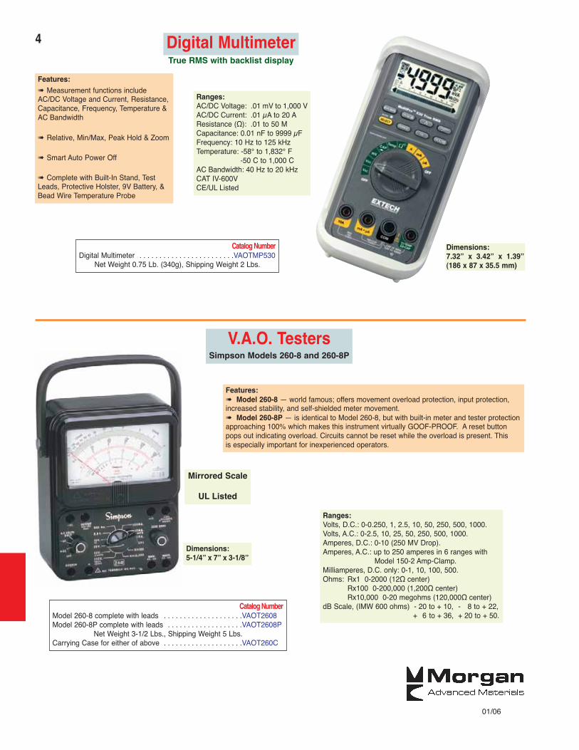
True RMS with backlist display
4
01/06
Dimensions:7.32” x 3.42” x 1.39”(186 x 87 x 35.5 mm)
Digital Multimeter
Features:� Measurement functions includeAC/DC Voltage and Current, Resistance,Capacitance, Frequency, Temperature &AC Bandwidth
� Relative, Min/Max, Peak Hold & Zoom
� Smart Auto Power Off
� Complete with Built-In Stand, TestLeads, Protective Holster, 9V Battery, &Bead Wire Temperature Probe
Ranges:AC/DC Voltage: .01 mV to 1,000 VAC/DC Current: .01 μA to 20 AResistance (Ω): .01 to 50 MCapacitance: 0.01 nF to 9999 μFFrequency: 10 Hz to 125 kHzTemperature: -58° to 1,832° F
-50 C to 1,000 CAC Bandwidth: 40 Hz to 20 kHzCAT IV-600VCE/UL Listed
Catalog NumberDigital Multimeter . . . . . . . . . . . . . . . . . . . . . . . .VAOTMP530
Net Weight 0.75 Lb. (340g), Shipping Weight 2 Lbs.
Ranges:Volts, D.C.: 0-0.250, 1, 2.5, 10, 50, 250, 500, 1000.Volts, A.C.: 0-2.5, 10, 25, 50, 250, 500, 1000.Amperes, D.C.: 0-10 (250 MV Drop).Amperes, A.C.: up to 250 amperes in 6 ranges with
Model 150-2 Amp-Clamp.Milliamperes, D.C. only: 0-1, 10, 100, 500.Ohms: Rx1 0-2000 (12Ω center)
Rx100 0-200,000 (1,200Ω center)Rx10,000 0-20 megohms (120,000Ω center)
dB Scale, (IMW 600 ohms) - 20 to + 10, - 8 to + 22,+ 6 to + 36, + 20 to + 50.
Catalog NumberModel 260-8 complete with leads . . . . . . . . . . . . . . . . . . . .VAOT2608Model 260-8P complete with leads . . . . . . . . . . . . . . . . . . .VAOT2608P
Net Weight 3-1/2 Lbs., Shipping Weight 5 Lbs.Carrying Case for either of above . . . . . . . . . . . . . . . . . . . .VAOT260C
Dimensions:5-1/4” x 7” x 3-1/8”
V.A.O. TestersSimpson Models 260-8 and 260-8P
Features:� Model 260-8 — world famous; offers movement overload protection, input protection,increased stability, and self-shielded meter movement.� Model 260-8P — is identical to Model 260-8, but with built-in meter and tester protectionapproaching 100% which makes this instrument virtually GOOF-PROOF. A reset button pops out indicating overload. Circuits cannot be reset while the overload is present. This is especially important for inexperienced operators.
Mirrored Scale
UL Listed
5
01/06
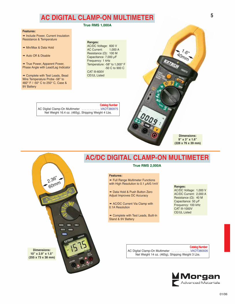
Dimensions:9” x 3” x 1.6”
(228 x 76 x 39 mm)
Features:� Include Power, Current InsulationResistance & Temperature
� Min/Max & Data Hold
� Auto Off & Disable
� True Power, Apparent Power,Phase Angle with Lead/Lag Indicator
� Complete with Test Leads, BeadWire Temperature Probe -58° to482° F / -50° C to 250° C, Case &9V Battery
Ranges:AC/DC Voltage: 600 VAC Current: 1,000 AResistance (Ω): 100 MCapacitance: 7,000 μFFrequency: 1 kHzTemperature: -58° to 1,000° F
-50 C to 900 CCAT III-600VCE/UL Listed
Catalog NumberAC Digital Clamp-On Multimeter . . . . . . . . . . . .VAOT380975
Net Weight 16.4 oz. (465g), Shipping Weight 4 Lbs.
1.6”40mm
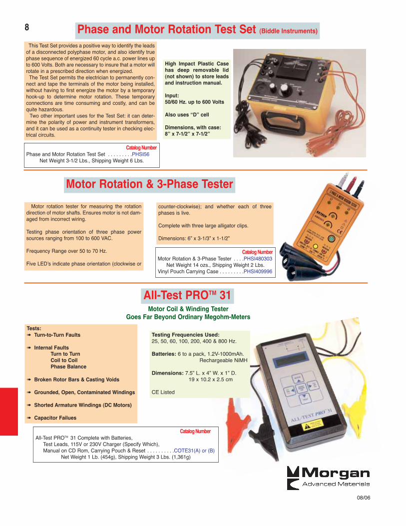
Dimensions:10” x 2.9” x 1.5”
(255 x 73 x 38 mm)
Features:� Full Range Multimeter Functionswith High Resolution to 0.1 μA/0.1mV
� Data Hold & Push Button ZeroAdjust Improves DC Accuracy
� AC/DC Current Via Clamp with0.1A Resolution
� Complete with Test Leads, Built-InStand & 9V Battery
Ranges:AC/DC Voltage: 1,000 VAC/DC Current: 2,000 AResistance (Ω): 40 MCapacitance: 50 μFFrequency: 100 kHzCAT III-1000VCE/UL Listed
Catalog NumberAC Digital Clamp-On Multimeter . . . . . . . . . . . .VAOT380926
Net Weight 14 oz. (465g), Shipping Weight 3 Lbs.
True RMS 2,000A
2.36”
60mm
AC DIGITAL CLAMP-ON MULTIMETERTrue RMS 1,000A
AC/DC DIGITAL CLAMP-ON MULTIMETER

6
01/06
Applications:Portability lends itself well to field service personnel with
many resistance measurement uses.Ideal for acceptance testing and preventative maintenance
of cables, wire harnesses, and motors.
Features:� 1000 V. Test Voltage� Two Ranges: 20 Megohm & 2000 Megohm,
with 2 % basic accuracy.� Auto Hold and Auto Power Off� Large 3-1/2 Digit (1999 count) multifunction
backlit LCD Display.
Megohm ProbeMeter™
Dimensions:7” x 1.7” x 1.6”
(17.8 x 4.3 x 4 mm)
Insulation Tester/MegohmmeterRanges:2000 Megohms @ 1000 VDC
200 Megohms @ 500 VDC200 Megohms @ 250 VDC200 Ohms600 Volts
Power Lock for 3 minute Test
Overload Protection
Large 0.65 LCD Display
Features:� Power Lock for 3 minute Test
� Overload Protection
� Large 0.65 LCD Display
Catalog NumberInsulation Tester/Megohmmeter with 6 - 1-1/2V batteries,
test leads and case . . . . . . . . . . . . . . . . . . . . . . . . . . . . .INST380360Net Weight 2 Lbs., Shipping Weight 3 Lbs.
Dimensions:6” x 4” x 2-1/2”
15.2 x 10.2 x 6.4 cm
Major Megger® Insulation andContinuity Tester
The rugged taut-band movement and all electronic circuitryassure maximum accuracy, reliability and durability.
Powered by an easy to crank, brushless D.C. generator drivingsolid state circuitry, this field model is always ready for use withno dependence on batteries or line power.
This unit is housed in an impact resistant poly carbonate casewith a carrying handle which folds flush into the case.
Readings are shown directly on an analog meter with a large,clear white-on-black scale.
Dimensions:5” x 4.5” x 7”
12.7 x 11.4 x 17.8 cm
Catalog NumberModel 212159 Major Megger Insulation and Continuity Tester
with 6 ft. leads and carrying case . . . . . . . . . . . . . . . . . . . . . . . . .MEGT212159Net Weight 2-1/2 Lbs., Shipping Weight 6 Lbs.
Ranges:0 to 2000 Megohms @ DC Test Voltages: 100V, 250V, 500V, & 1000VResistance: 0-5000 Ohms
Megohm ProbeMeter complete with Catalog Numbercarrying case and 4 AAA batteries . . . . . . . . . . . . . . . .MEGT403360
Net Weight with accessories and case 10 ozs., Shipping Weight 2 Lbs.
Ranges:Range Resolution Accuracy (%rdg+digits)
Insulation Resistance: 20MΩ 0.01MΩ ±(2% + 2d)2000MΩ 1MΩ <500MΩ ±(4% + 2d) >500MΩ ±(5% + 2d)
Insulation Test Voltage: 1000VPower Source: Four 1.5V AAA batteries; External Jack; 200hr battery life

7AC - High Voltage Insulation TestersHigh voltage insulation testers indicate breakdowns, grounds, and shorts. Use them to apply a
high-voltage test at various steps in the manufacture or repair of electrical products. This permitsearly detection of insulation weakness or failure that might otherwise show up only in the actualuse.
These testers are built with a breakdown light which also serves as an “on” light. This indicatinglight dims or goes out completely to indicate a problem.
In addition, 4 models have a built-in safety switch that immediately stops current flow in the eventof a breakdown. Along with the visual indication of a problem these units also have a buzzerwhich signals a problem. These units will shut down in the event of a breakdown and will not startup again until the start/reset button is reset.
All units are supplied with self retracting probed test leads. The probes are spring loaded andhoused within the insulated fibre handles. The fibre slide buttons are pressed to expose the testprobes. This safety feature minimizes the chance of accidental contact with the probes.
Output Automatic CatalogModel 115 V. 230 V. Meter Shutdown Number2109 √ √ INST2109A2110 √ INST2110A2119 √ √ √ INST2119A2120 √ √ INST2120A2129 √ √ INST2129B2130 √ INST2130B2139 √ √ √ INST2139B2140 √ √ INST2140B
Ranges:Five Test Voltages: 500, 1080, 1250, 1750,
2000 and 2500V
Net Weight 18 Lbs., Shipping Weight 20 Lbs.
Model 2503, with Safety Probe with 6 ft. lead, Catalog NumberGround Return Clip with 6 ft. lead, andHigh Voltage Clip with 6 ft. lead . . . . . . . . . . . . . . . . . . . . . .MEGT2503
Net Weight: 16 Lbs., Shipping Weight: 18 Lbs.
Ranges:Input Voltage: 115/230V selectable
Output: Rating: DC 0 - 5000V, 3 mA
Voltage Setting: 0V - 5kV, 10 volts/step
Ripple: < 5% at 5KVDC / 3 mA
Dwell Time: 0, 1 or 60Setting: “0” for continuous running
Ramp Timer: 0 and 0.2 - 999.9 seconds, 0.1 second / step0 ramp setting = 0.1 seconds fixed ramp
Failure Settings: High Limit: 0.02 - 3.00 mA, 0.01 mA / StepAccuracy: ± (2% of setting + 0.02 mA)
Voltmeter (4 digits): Range: DC 0.00 - 5.00 KVAccuracy: ± (2% of reading + 10 V)
Ammeter (4 digits): Range: DC 0.00 - 3.00 mAAccuracy: ± (2% of reading + 0.02 mA)
Timer Display: Range: 0.0 - 999.9 seconds
Dimensions: 4-3/4” x 5-3/4” x 14-1/2”12 x 14.6 x 36.8 cm
5000V DC Hipot
Features:� This model meets the UL, CSA, VDE, IEC, and UL 120K Ohm testrequirement. This unit feature audible and visual failure alarms, andshut off high voltage upon reject.
� Operators can set output voltages and trip currents to desiredlevels in the absence of any high voltage, a key safety feature thatconventional analog hipot testers lack.
� Easy-to-read digital display simplifies the task of setting test parame-ters and interpreting test results. Meter memory allows operators toreview the last test results.
8
08/06
Phase and Motor Rotation Test Set (Biddle Instruments)
This Test Set provides a positive way to identify the leadsof a disconnected polyphase motor, and also identify truephase sequence of energized 60 cycle a.c. power lines upto 600 Volts. Both are necessary to insure that a motor willrotate in a prescribed direction when energized.
The Test Set permits the electrician to permanently con-nect and tape the terminals of the motor being installed,without having to first energize the motor by a temporaryhook-up to determine motor rotation. These temporaryconnections are time consuming and costly, and can bequite hazardous.
Two other important uses for the Test Set: it can deter-mine the polarity of power and instrument transformers,and it can be used as a continuity tester in checking elec-trical circuits.
Catalog NumberPhase and Motor Rotation Test Set . . . . . . . . .PHSI56
Net Weight 3-1/2 Lbs., Shipping Weight 6 Lbs.
High Impact Plastic Casehas deep removable lid(not shown) to store leadsand instruction manual.
Input:50/60 Hz. up to 600 Volts
Also uses “D” cell
Dimensions, with case:8” x 7-1/2” x 7-1/2”
Motor Rotation & 3-Phase Tester
Motor rotation tester for measuring the rotationdirection of motor shafts. Ensures motor is not dam-aged from incorrect wiring.
Testing phase orientation of three phase powersources ranging from 100 to 600 VAC.
Frequency Range over 50 to 70 Hz.
Five LED’s indicate phase orientation (clockwise or
counter-clockwise); and whether each of threephases is live.
Complete with three large alligator clips.
Dimensions: 6” x 3-1/3” x 1-1/2”
Catalog NumberMotor Rotation & 3-Phase Tester . . . .PHSI480303
Net Weight 14 ozs., Shipping Weight 2 Lbs.Vinyl Pouch Carrying Case . . . . . . . . .PHSI409996
Motor Coil & Winding TesterGoes Far Beyond Ordinary Megohm-Meters
Tests:� Turn-to-Turn Faults
� Internal FaultsTurn to TurnCoil to CoilPhase Balance
� Broken Rotor Bars & Casting Voids
� Grounded, Open, Contaminated Windings
� Shorted Armature Windings (DC Motors)
� Capacitor Failues
Testing Frequencies Used:25, 50, 60, 100, 200, 400 & 800 Hz.
Batteries: 6 to a pack, 1.2V-1000mAh.Rechargeable NiMH
Dimensions: 7.5” L. x 4” W. x 1” D.19 x 10.2 x 2.5 cm
CE Listed
Catalog NumberAll-Test PROTM 31 Complete with Batteries,
Test Leads, 115V or 230V Charger (Specify Which),Manual on CD Rom, Carrying Pouch & Reset . . . . . . . . . .COTE31(A) or (B)
Net Weight 1 Lb. (454g), Shipping Weight 3 Lbs. (1,361g)
All-Test PROTM 31

9
08/06
Model 101 Bar to Bar TesterState Of The Art — Easy To Use — Eliminates Guesswork
This meter will check any armature that has enough resistance tomove the meter needle into the green or “OK” section of the meterface during the initial “zeroing-in”. On a large armature which hasvery little resistance, the meter needle will show less deflection butenough to establish a starting point.“Dead shorts” are detected by a reading on that portion of the meter
and even partial shorts can be detected by a deflection from the“zeroing-in” point that the test was started from.
The color coded meter face also has indications for open andreversed coils.
� One meter/One setting indicates circuit OK, shorted, open, or reversed
� Eliminates guesswork — zeroes right in on problem circuit� Never again strip a good armature only to find equalizers
caused a short to be indicated� Sensitive enough to identify unsatisfactory circuits that other
testers cannot find� Pays for itself by eliminating unnecessary repairs or expensive
second teardowns� A quality buy, this highly scientific and advanced test equipment
will maintain or increase in value
Catalog NumberModel 101 Bar to Bar Tester . . . . . . . . .INST101
Net Weight 2 Lbs., Shipping Weight 3 Lbs.
Catalog NumberModel MAS Bar to Bar Tester, 115 V. . . .INSTMASModel MAS Bar to Bar Tester, 230 V. . .INSTMASB
Net Weight 28 Lbs., Shipping Weight 33 Lbs.
Operates on 2 “D” cells
Model MAS Bar to Bar TesterMainframe
Armature Head
Magnetic Head
The Model MAS Mainframe is a self contained unit that forms the basic component of the motorAnalysis System. The Mainframe contains the necessary power supplies, amplifiers and logic nec-essary to drive the various heads and probes allowing numerous tests on a wide range of rotatingequipment. Auxiliary heads may be added at any time and require no modification or alteration tothe Mainframe. The Mainframe comes complete with a 7 foot cable that interfaces with the heads.
The Armature Head performs a four point AC variable frequencytest on DC armatures. TheArmature Head in conjunction with theMainframe automatically selects one of four thousand different fre-quencies and power levels to match the armature being tested. Theautomatic feature makes this head fast to set up and easy to use.This permists accurate and repeatable analysis of most commonarmature problems such as shorts, opens, crossed connections,partial opens or shorts and misconnects. Armatures with equalizersand uneven turns are also easily tested. These features make thisBar to Bar Tester affordable and practical.
The Field Coil & Neutral Plane Test Head allows testing of seriesfields, interpoles and shunt fields. When used with the flux probe itis possible to test most coils in the machine without breaking theindividual coil connections or isolating the coils from one another.The test quickly identifies coil polarity. The probe measures theimpulse magnetic field flux generated by each coil allowing a rela-tive comparison between coils. Shorted turns are indicated as areduction in flux generated by a coil. This head allows easy and pre-cise setting of neutral plane.
Since this head supplies all impulse power to the fields being test-ed, there is no need to connect the motor to a test panel or any otherpower source.
This head comes with the Flux Probe and all necessary cables.
Specifications:Main Frame:
120 V or 220 VSize: 10-1/2 x 7-1/2 x 15”Weight: 26 lbs. net
Armature Head:Power supplied by Main FrameTest Frequency: 100hz 5khzMax. Current Output: 2.5 amps true rmsReadout: 30 segment solid state bar graph
Field Coil & Neutral Plane Test Head:Power supplied by Main FrameOutput: Unipolar pulseOutput Current: 40amps (short circuit)Pulse Width: 6ms and .5secRepetition Rate: 10hz and 1.5hz switch selectableReadout: 30 segment bar graph

10
At Right:Type B-1-M Adjustable BenchGrowler with meter and conti-nuity test.
At Left:Type B-1 Adjustable
Bench Growler
General InformationWhen an alternating current is passed through a Growler, it sets up a
magnetic flux in the iron of the armature or stator spanned by the jawsof the Growler.As this flux passes through any coil, it induces a potential. A current will
flow if the coil is short-circuited. When current flows, it sets up a mag-netic field around the shorted coil which can be detected with an ironfeeler. (The increased load on the Growler sometimes changes the toneof the hum; hence the name “Growler”.) In many cases a meter can beused to measure a change in magnetic flux (Type B-1-M), or to measurethe increased current requirements of the Growler (M-1 Meter-Unit).
Open coils can also be found; see discussion below.
Foot-SwitchA Foot-Switch with an 8 ft. line cord, and a female connection is available
for use with any of the Growlers. Large armatures cannot be easily rotatedwithout shutting off the Growler current. This is conveniently done with theFoot-Switch, while the hands are left free to turn the armature.
Types F and I-X are similar in appearance, with built-in feeler as pictured,except the feeler on Model I-X is adjustable, which gives it a wider range ofapplications. Both have fixed jaws 2” long, and a thumb-switch.
Both can be used in stators as small as 2-3/8” inside diameter, and onarmatures from 2-1/2” diameter up. The built-in feeler makes testing a one-hand operation, and is especially desirable in small stators where there isn’troom for a separate feeler. The adjustable feeler on the I-X is more satisfac-tory where a variety of large and small armatures and stators are involved.
How Growlers Are UsedThe most common way of using a Growler is the “feeler method” in which
the Growler spans a slot containing a coil, and a “feeler” of iron, such as ahack-saw blade is held about 1/4” above the slot containing the other side ofthe same coil.
Open CircuitsOpen circuits can be detected by shorting adjacent commutator bars with a
screw driver, or any other piece of metal. Good coils will spark as the barsare shorted. No sparks indicate the coil is open. Test field coils by shortinglead wires. Another way is to use a continuity tester — such as the one onthe M-1 Meter Unit and B-1-M Growler, or others shown in this catalog.
Grounds can also be detected with a continuity tester.
Type B-1 has adjustable jaws 2-1/2” long. Armature capacity: 1” to18”diameter. There are no obstructions at the ends of the jaws, thus allow-ing small armatures with fans, bearings, etc., to fit properly.
Type B-1-M is the same size as B-1, and has in addition a meter andcontinuity test prods. The meter is connected to a secondary winding onthe Growler and shows changes in magnetic flux as shorts are encoun-tered. The test prods are used to detect grounds. A light in one prodglows when a circuit is complete. The test current is 1 milliampere at 115volts — shock-proof, and safer than required. Both prods are protectedfrom ground.
Type U-2 Growler has adjustable jaws 4” long, and may be used onarmatures over 1”, and on stators over 5-3/4” inside diameter. The U-2can be used with the M-1 Meter Unit.
Both B-1 and B-1-M have Adjustable Jawswith Face Length 2-1/2”.
Type U-2 Universal Adjustable Growlermay be used as both an external
Growler for armatures and an InternalGrowler for stators.
Adjustable Jaws. Face Length 4”.
No. M-1 Meter UnitM-1 Meter Unit isdesigned for use with theU-2 Growler. The metershows variations in theline current drawn by theGrowler when a short isencountered. The adjust-ing knob sets the meterpointer to mid-scale on agood coil. The test prodsare used for detectinggrounds, as on the B-1-M.
Type F and Type I-Xboth have built-infeeler. Type F has
fixed position feeler,Type I-X feeler is
adjustable.
If the coil is short-ed the feeler willbe pulled down tothe slot and willstick and vibrate.The action is verypositive and is rec-ognized instantly.
The feeler canalso be used onthe same side ofthe coil that isspanned by theGrowler, either a
separate feeler or the convenient built-in feeler of Types F and I-X.
Range for Range for Catalog NumberLength Armatures, Stators Weight — Lbs. 115 V. 230 V.
Type Face Diameter Diameter Net Ship 50/60 Hz. 50/60 Hz.U-2 4” 1” & up 5-3/4” & up 18-3/4 20 GRLRU2A GRLRU2BB-1 2-1/2” 1” - 18” — 11-1/4 12-1/2 GRLRB1A GRLRB1BB-1-M 2-1/2” 1” - 18” — 12 15 GRLRB1MA GRLRB1MBF 2” 2-1/2”-12” 2-3/8”-12” 3-1/2 5-1/2 GRLRFA GRLRFBI-X 2” 2-1/2”-12” 2-3/8”-12” 3-1/2 5-1/2 GRLRIXA GRLRIXBM-1 Meter Unit — — 4-3/4 6-3/4 GRLR23A GRLR23BFoot Switch — — 2-1/2 3-1/2 JGRLFSA GRLR19
Specifications
Type F and I-X Growler
Martindale Growlers

11
01/06
The Model 1726 Hand-Held Digital Tachometer isa dual function instrument providing contact andnon-contact measurement of rotational and linearmotions. With an accuracy of .025% of indicatedreading 1 LSD, this unit is ideal for use in produc-tion, engineering, inspection, and maintenance.This unit offers sixteen different functions of mea-
surement from 6 - 99,999 RPM to .033 - 53 F/S,plus 14 more ranges.
Checks and analyzes motion and speed by sim-ply aiming and synchronizing its flash rate (fpm)with a rotating object. Read RPMS on 4 digit LEDdisplay. Duty cycles from 5 to 30 minutes. Highaccuracy over a wide, dynamic range via exclu-sive microcomputer LSI circuit and crystal controltime-base.
Ideal for measuring the speed of moving gears,fans, pumps, motors and other equipment used ingeneral maintenance, production, quality controlor laboratories.
Complete with 6 ft. power cord, handle and canbe tripod mounted.
Martindale Hand Tachometers
Digital Photo/Contact Tachometer
Dual Function Digital Tachometer
Digital Stroboscope/TachometerFreeze motion and measure speed without contact
Catalog NumberModel 461895 Tachometer with accessories and case . . . .TACH461895Net Weight with accessories & case 1 Lb. 10 oz., Shipping Weight 3 Lbs.
Catalog NumberModel 1726 Tachometer with accessories and case . . . . . . .TACH1726Net Weight with accessories & case 1 Lb. 10 oz., Shipping Weight 3 Lbs.
Catalog NumberDigital Strobo Tach, 115 V. AC, 60 Hz. . . . . . . . . . . . . . . . . .TACH461830Digital Strobo Tach, 220 V. AC, 50 Hz. . . . . . . . . . . . . . . . . .TACH461831
Net Weight 2.2 Lbs., Shipping Weight 4 Lbs.Spare Xenon Lamp (est. life 300 hrs.) . . . . . . . . . . . . . . . . .TACH461834
Specifications:Flash/Speed Rate: 100 to 10,000 fpm/rpmAccuracy: ± (0.05% rdg + 1d)Dimensions: 8.3 x 4.8 x 4.8”
Range:
Í5.0 to 99,999 RPM (Photo Mode)Í0.5 to 19,999 RPM (Contact Mode)Í0.2 to 6,560 ft./min.Í0.05 to 1,999 m./min.Accuracy: ±(0.057 + 1 digit)
The Model 461895 can be used two differentways, either as a direct contact style tach or anon-contact photo tach, depending on the typeof work being performed or the preference ofthe operator.The 5 digit LCD display gives exact RPM read-
ings and eliminates the need to use a multiply-ing factor or calculate readings while watchingan indicator needle fluctuate.The Memory Recall feature allows recall of the
last value recorded from the memory storage.Accessories include two rubber tips, one sur-
face speed test wheel, and two ft. of reflectingtape. Uses 4 x 1.5 V. AA batteries.
Features: Contact or Non-Contact Measurement8 Character Display16 Units of MeasureUnit of Measure Always DisplayedPower Source 9V BatteryMemory3 Accessory Tips IncludedCase Included

12
01/06
Surface Temperature Tester
High Temperature InfraRed Thermometer
Catalog NumberModel 312F (Fahrenheit) . . . . . . . . . . . . . . . . . . . . . . . . . . . . . . .TEMP312F
Net Weight 2 oz., Shipping Weight 6 oz.
Calibrated Fahrenheit or Centigrade
Ranges:-58° to 1400° F-50° to 760° C
Accuracy:+2%+2°<932° F (500° C)+2.5%+5°>932° F (500° C)
Field of View:12:1 Distance to Target RatioA 1” Square Target Area can be accuratelyread from a distance of 12 feet
Dimensions:3.9” x 2.2” x 9” (100 x 56 x 230mm)
� Automatic Data Hold
� Auto Power Off
Catalog NumberInfraRed Thermometer with 9V Battery . . . . . . . . . . . . . . . .TEMP42540
Net Weight 10.2 oz. (290g), Shipping Weight 3 Lbs. (1,361g)
Non Contact MesurementsWith Laser Pointer & 2000 Count Backlit LCD Display
Accuracy is ± 2%of full scale
Built-in magnetshold tester tonon-horizontal
ferrous surfaces.
Model 312F is built for rough industrial use without any lesseningof accuracy. The bimetallic sensor is a specialty processed alloythat is conditioned and tested for permanent calibration and max-imum stability.
Recommended primarily for temperature measurement of elec-tric motors and generators, bearings, etc., this tester can be usedfor checking any other surface within the range of 0° F to 250° F.Calibration is for use in an ambient temperature of about 70° F.Higher or lower surrounding air temperatures will result in slightlyhigher or lower readings. Three minutes should be allowed for theinstrument to reach full stability when taking a reading.The more nearly flat the surface being measured, the better con-
tact will be made by the sensor. The magnets provide convenienttemporary or permanent mounting to any ferrous surface, but theinstrument is equally effective on non-ferrous horizontal surfaces.Dimensions: 2” diam. x 1/2” thick.

13
08/06
Spring Pressure Formula
(For recommended spring pressures, contact your motor manufactuer.)
Brush Tension Scale
Compact size for fast, easy readings.Efficient, durable and small enough to fit in your hand, this Electronic
Digital Scale is the convenient way to measure brush holder springforce. Simply attach the interchangeable strap or hook to the springassembly and pull the scale taut by the comfort-grip handle. The mea-sured force is clearly displayed in easy-to-read, 1/2” LCD numerals.
Precise Spring Force MeasurementsThe battery-operated Digital Scale accurately reads force measure-
ments of both spiral torsion springs and constant force springs up to 15lbs. (+ or - 2 oz.). Convenient automatic zeroing ensures measurementof only the spring force.
Spring Pressure (P.S.I.) =Measured Force (Lbs.)
Brush Thickness (in.) X Brush Width (in.)
This tool provides a low cost method of locating and identifying worn motor and equipment bearingsand bushings, worn gears, and other trouble spots which can be traced by sound. The 2-piece probereaches 11-3/4”.
Repairman’s Stethoscope
For “Pull” Testing
Catalog NumberBrush Tension Scale,
15 lb. capacity . . . . . . . . .BRTSIN15ELNet Weight 9 Ozs., Shipping Weight 2 Lbs.
Catalog NumberRepairman’s Stethoscope . . . . . . . . . .MARTRS
Net Weight 6 ozs., Shipping Weight 1 Lb.
Morgan Advanced MaterialsPostbus 362 De Oude Veiling3 1620 AJ Hoorn 1689 AA Zwaag
Tel. : +31(0) 229 255555 Fax : +31(0) 229 255541
www.morganelectricalmaterials.com [email protected]