Electrical Systems Safety w/Change 3 (7/10/2017) · Electrical Systems Safety w/Change 3...
30
Printed copies are uncontrolled and are not to be used for operational purposes. GLP-QS-8715.1.8 Verify current version before use at Page 1 of 30 https://knowledgeshare.grc.nasa.gov/bmslibrary Document Number: GLP-QS-8715.1.8 Revision: Revision E Effective Date: 6/24/2016 Expiration Date: 6/24/2021 Glenn Safety Manual – Chapter 8 Electrical Systems Safety w/Change 3 (7/10/2017) Approved by: QS/Chief, Safety and Health Division Distribution: BMS Library NASA - Glenn Research Center Cleveland, OH 44135
Transcript of Electrical Systems Safety w/Change 3 (7/10/2017) · Electrical Systems Safety w/Change 3...

Printed copies are uncontrolled and are not to be used for operational purposes. GLP-QS-8715.1.8 Verify current version before use at Page 1 of 30
https://knowledgeshare.grc.nasa.gov/bmslibrary
Document Number: GLP-QS-8715.1.8
Revision: Revision E
Effective Date: 6/24/2016
Expiration Date: 6/24/2021
Glenn Safety Manual – Chapter 8
Electrical Systems Safety
w/Change 3 (7/10/2017)
Approved by: QS/Chief, Safety and Health Division
Distribution: BMS Library
NASA - Glenn Research Center
Cleveland, OH 44135

Glenn Research Center
Glenn Safety Manual
Title: Electrical Systems Safety
Document No.: GLP-QS-8715.1.8 Rev.: Revision E
Printed copies are uncontrolled and are not to be used for operational purposes. GLP-QS-8715.1.8 Verify current version before use at Page 2 of 30
https://knowledgeshare.grc.nasa.gov/bmslibrary
Change Record
Rev. Effective
Date
Expiration
Date
GRC25,
Change
Request #
Description
D 6/9/11 6/9/2016 121 Bi-annual Review/Revision
Change 1 4/23/14 6/9/2016 N/A Administrative change to add front cover and
change history log to comply with NPR 1400.1.
E 6/24/16 6/24/2021 15-018
70E requirements and GRC expectations to meet
them, (5.7) Incorporate on-site knowledge
requirements, (6.1) Incorporate NPR medical
requirement statement, (6.2) Allow safety
program grace period to respond to code
changes, (6.5) Clarification, (6.7) New NFPA
70E requirements for "Buddies", (6.9.4) Closer
reference to NFPA 70E requirements, (6.10)
Clarify responsibility of classification
determination, (6.11.2) Clarification, (6.11.3)
Clarification of DSP responsibilities, (6.13.2)
Remove redundant information already covered
in System Manager Operating Instructions,
(6.15.1) Update training requirements to
coincide with NFPA 70E and IFO Audit
Findings, (6.15.2) Meet NFPA 70E three year
retraining requirement, one year on AED , CPR
and release of victims.
Change 1 8/16/16 6/24/2021 N/A
Administrative change to add “In addition, at
GRC, whenever the Restricted Arc Flash
Boundary is crossed, by reach or tool,” and
added “see Appendix D.”
Change 2 1/11/17 6/24/2021 N/A Administrative change to revise title and
audience of the training class within 6.15.1
Change 3 7/10/2017 6/24/2021 N/A
Administrative change to change Document
Number from GLM-QS-1700.1 to GLP-QS-
8715.1.
**Include all information for each revision. Do not remove old revision data. Add new rows to table
when space runs out by pressing the tab key in the last row, far right column.

Glenn Research Center
Glenn Safety Manual
Title: Electrical Systems Safety
Document No.: GLP-QS-8715.1.8 Rev.: Revision E
Printed copies are uncontrolled and are not to be used for operational purposes. GLP-QS-8715.1.8 Verify current version before use at Page 3 of 30
https://knowledgeshare.grc.nasa.gov/bmslibrary
Contents
1.0 PURPOSE............................................................................................................................................................ 5 2.0 APPLICABILITY ............................................................................................................................................... 5 3.0 BACKGROUND ................................................................................................................................................. 5 4.0 POLICY ............................................................................................................................................................... 6
4.1 GRC Policy ................................................................................................................................................ 6 4.2 Measurement and Verification .................................................................................................................. 6
5.0 RESPONSIBILITIES .......................................................................................................................................... 6 5.1 GRC Fire Protection - Authority Having Jurisdiction (AHJ) .................................................................... 6 5.2 Safety and Health Division (SHeD)........................................................................................................... 6 5.3 Area Safety Committees ............................................................................................................................ 6 5.4 Electrical Applications Safety Committee ................................................................................................. 6 5.5 Process Systems Safety Committee (PSSC) .............................................................................................. 7 5.6 Electrical Systems Managers ..................................................................................................................... 7 5.7 Plum Brook Station Electrical Maintenance Specialist: ............................................................................ 7 5.8 Electrical Power Dispatcher (EPD phone # 433-3100) ............................................................................. 7 5.9 Supervisory Personnel ............................................................................................................................... 7 5.10 Qualified Person ........................................................................................................................................ 8 5.11 Certified Operator/Switchperson ............................................................................................................... 8
6.0 REQUIREMENTS .............................................................................................................................................. 8 6.1 Physical Ability Requirements (NPR 8715.3, Section 7.4) ........................................................................ 8 6.2 Codes, Standards, and Instructions ............................................................................................................ 8
6.2.1 National Electrical Code (NEC) (NFPA 70) ............................................................................... 9 6.2.2 National Electrical Safety Code (NESC) (IEEE C2) ................................................................... 9 6.2.3 Standard for Electrical Safety in the Workplace and Arc Flash Protection (NFPA 70E) ............ 9 6.2.4 Occupational Safety and Health Act (OSHA) (29 CFR 1910 and 29 CFR 1926)....................... 9 6.2.5 NASA General Safety Program Requirements (NPR 8715.3) .................................................... 9 6.2.6 Electric Power System Operating Instructions (LVEPS–OI xx and HVEPS–OI xx) ................... 9
6.3 Shock ......................................................................................................................................................... 9 6.4 Electrical Isolation (NFPA 70E, Article 130) .......................................................................................... 10 6.5 Lockout/Tagout Procedures (OSHA 29 CFR 1910.147 and GLM–QS–1700.1 Chapter 9) ..................... 11 6.6 Consider All Electrical Systems Energized (NFPA 70E, Article 120) .................................................... 11 6.7 Buddy System (NPR 8715.3C Chapter 3.6 Electrical Safety) ................................................................. 11 6.8 Work in a Confined Space (29 CFR 1910.146, 29 CFR 1910.269, and ANSI Z117.1) ........................... 11 6.9 General Electrical Considerations ........................................................................................................... 11
6.9.1 Configuration Control (GLP-FB-8820.1) .................................................................................. 11 6.9.2 Validation of Operating Equipment (LVEP and HVEP OIs) .................................................... 12 6.9.3 Separately Derived Electric Power Systems (NFPA 70 and 70E) ............................................. 12 6.9.4 Battery Systems (NEC Article 480, NFPA 1 Chapter 25) ......................................................... 12 6.9.5 Instrument Transformers (NEC Article 250.170) ...................................................................... 13 6.9.6 Capacitors (NEC Article 460, NFPA 70E Article 120) ............................................................. 13
6.10 Hazardous (Classified) Locations (NFPA 70, Articles 500 through 516) ............................................... 14 6.11 Special High-Voltage Electrical Safety Considerations (HVEPS–OIs) ................................................... 14
6.11.1 High-Voltage Electrical Power System Operating Instructions (HVEPS–OI-012) ................... 14 6.11.2 NASA GRC High-Voltage Designated Safety Person (DSP) (Specific HVEPS-OI-
012) ........................................................................................................................................... 14 6.11.3 Entry into Electric Supply Stations (Specific HVEPS-OI-012) ................................................ 15 6.11.4 Work On or Near High-Voltage Facilities ................................................................................ 15 6.11.5 Work in Electric Supply Stations or Near Exposed Lines or Apparatus (HVEPS-OI-
012) ........................................................................................................................................... 15 6.11.6 High-Voltage Switching (Specific HVEPS-OI-011) ................................................................. 16 6.11.7 Cutting High-Voltage Cables (HVEPS-OI-009) ....................................................................... 16

Glenn Research Center
Glenn Safety Manual
Title: Electrical Systems Safety
Document No.: GLP-QS-8715.1.8 Rev.: Revision E
Printed copies are uncontrolled and are not to be used for operational purposes. GLP-QS-8715.1.8 Verify current version before use at Page 4 of 30
https://knowledgeshare.grc.nasa.gov/bmslibrary
6.11.8 Fuses (Removal and/or Replacement) – (NFPA 70E and GLM-QS-1700.1.8)......................... 16 6.11.9 Lifting and Construction Equipment, Vehicles, or Personnel Near Exposed Energized
Electrical Parts (HVEPS-OI-012) .............................................................................................. 17 6.12 Personal Protective Equipment (for additional information on PPE see GSM Chapter 15) .................... 17
6.12.1 Hard Hats (29 CFR 1910.135 and ANSI Z89.1) ........................................................................ 17 6.12.2 Eye Protection (ANSI Z87.1 and ASTM F 2178) ....................................................................... 17 6.12.3 Safety Shoes (ASTM F2412 and F2413) ................................................................................... 17 6.12.4 Rubber Insulating Gloves (ASTM D 120 and ASTM F 496) ..................................................... 17 6.12.5 Hot Sticks (ANSI/IEEE Standard 516 and 29 CFR 1910.269(j)) .............................................. 17 6.12.6 Protective Clothing (NFPA 70E) ............................................................................................... 18
6.13 Equipment Safety Tests and Checks (ANSI/IEEE or NETA) ................................................................... 18 6.13.1 Tests To Be Performed Prior to Initial Energization ................................................................. 18 6.13.2 Circuit-Interrupting Devices ...................................................................................................... 18 6.13.3 Protective System Checks ......................................................................................................... 19 6.13.4 High-Voltage Insulation Testing ............................................................................................... 19
6.14 Experimental Equipment (GLM–QS–1700.1) ......................................................................................... 19 6.14.1 Safety Responsibility ................................................................................................................. 19 6.14.2 Experimental, Developmental, or Flight-Level Electrical/Electronic Equipment
(NFPA 70E) .............................................................................................................................. 19 6.14.3 Experimental Equipment Utilizing High-Voltage Capacitor Banks .......................................... 20
6.15 Training (NASA General Safety Program Requirements NPR 8715.3C) ............................................... 21 6.15.1 Initial Training........................................................................................................................... 21 6.15.2 Employee Retraining ................................................................................................................. 21
7.0 RECORDS ......................................................................................................................................................... 22 8.0 REFERENCES .................................................................................................................................................. 22 APPENDIX A . Definitions and Acronyms ............................................................................................................... 24 APPENDIX B . Examples of Signs AND LABELS .................................................................................................. 26 APPENDIX C . Correlation of Current in Amperes and Reaction with the Human Body .......................................... 28 APPENDIX D. “When is the Buddy System Required During Electrical Applications”............................................ 29

Glenn Research Center
Glenn Safety Manual
Title: Electrical Systems Safety
Document No.: GLP-QS-8715.1.8 Rev.: Revision E
Printed copies are uncontrolled and are not to be used for operational purposes. GLP-QS-8715.1.8 Verify current version before use at Page 5 of 30
https://knowledgeshare.grc.nasa.gov/bmslibrary
Chapter 8—Electrical System Safety
Note: The current version of this chapter is maintained and approved by the Safety and Health
Division (SHeD). The last revision date of this chapter was June 2016. The current version is
located within the BMS Library. Approved by Chief of Safety and Health Division.
1.0 PURPOSE
This chapter sets forth minimum electrical safety guidelines and standards within the framework of the Glenn
Research Center (GRC) safety policies and constraints. Electrical systems safety encompasses the responsibilities,
regulations, and requirements that ensure a safe working environment for personnel engaged in electrical work at
GRC. Minimizing hazards such as shock, arc flash, and arc blast is necessary for providing an electrically safe work
environment.
2.0 APPLICABILITY
The provisions of this chapter are applicable to all NASA employees and to all other agencies, organizations, and
contractor personnel, who design, construct, inspect, operate, maintain, or manage electrical systems within the
confines of GRC at Lewis Field and Plum Brook Station. It is for professional designers, engineers and craftsman; it
is not an instructional manual for untrained personnel nor is it a substitute for the detailed procedures judged
necessary for the safe conduct of a specific electrical task.
In this chapter, all mandatory actions (i.e., requirements) are denoted by statements containing the term “shall.” The
terms “may” or “can” denote discretionary privilege or permission, “should” denotes a good practice and is
recommended, but not required, “will” denotes expected outcome, and “are” or “is” denotes descriptive material.
3.0 BACKGROUND
The authority for the Electrical Systems Safety chapter is derived from the “NASA General Safety Program
Requirements,” NASA Procedural Requirement (NPR) 8715.3C, Chapter 3.6. Electricity is a common source of
energy that GRC personnel are exposed to on a daily basis. It provides lighting, power to computers, and numerous
manners of creature comfort. Electricity is something we have grown accustomed to using and feeling safe around,
but it is that feeling of complacency that can turn electricity into one of the most dangerous and unforgiving energy
sources we are exposed to. Numerous personnel injuries and fatalities have occurred through the years because
unqualified persons have exposed themselves to unsafe and unguarded sources of electricity. Even trained personnel
have lost their lives because of unforeseen circumstances. Electricians may think that an electrical-related accident
or injury cannot happen to them, or even worse, may accept that risks are just part of the job. Accidents are not
prevented based on one’s knowledge of electricity; they occur because of unforeseen circumstances that place you in
harm’s way. Codes, standards, and regulations, listed later in this chapter, have been put in place so that trained
personnel take the proper precautions to safeguard against incidents and mishaps. If a conflict in procedure arises
between this chapter and local, State or Federal regulations, the most stringent requirements shall apply.
The Glenn Research Center at Lewis Field and Plum Brook Station, is varied in its electrical systems. There are
high- and low-voltage, protective/security, central process, and research systems that differ in the types of work
performed within and on these systems as well as hazards these systems might introduce. There are indoor, outdoor
(including substations with exposed energized equipment), and underground (manholes/vaults, duct banks, etc.)
components that make up these electrical systems. This document describes the different types of activities that take
place on the electrical systems at GRC as well as the different voltage exposure levels to personnel. It describes the
responsibilities of both personnel who are in charge of and those that work on these systems and the minimum
training required.
Glenn Research Center
Glenn Safety Manual
Title: Electrical Systems Safety
Document No.: GLP-QS-8715.1.8 Rev.: Revision E
Printed copies are uncontrolled and are not to be used for operational purposes. GLP-QS-8715.1.8 Verify current version before use at Page 6 of 30
https://knowledgeshare.grc.nasa.gov/bmslibrary
4.0 POLICY
4.1 GRC Policy
It is GRC policy that electrical systems be designed, operated, and maintained to adequately control hazards likely to
cause death or serious physical harm or severe system damage. This will be accomplished by following the
Occupational Safety and Health Administration (OSHA) and industry accepted standards and policies (See
Requirements section 6.0)
4.2 Measurement and Verification
Compliance with the responsibilities and requirements of this chapter are measured and verified through the use of
programmatic self-assessments, regulatory and agency audits and internal field inspections and surveys.
5.0 RESPONSIBILITIES
Specific responsibilities of individuals or organizations tasked with establishing and following safety requirements
for electrical systems utilized at GRC are as follows:
5.1 GRC Fire Protection - Authority Having Jurisdiction (AHJ)
The individual responsible for implementing the fire safety provisions of NPR 8715.3, "NASA General Safety
Program Requirements," and with the authority for "approving/concurring in" associated installations, procedures,
and equipment. The AHJ shall be permitted to render code interpretations in order to provide clarification to its
requirements and approve variations/deviations to those requirements where it can be shown that alternative
methods* can still maintain an effective level of safety. Existing electrical installations that do not comply with the
provisions of updated/current codes shall be permitted to be continued in use unless the AHJ determines that the
lack of conformity with the updated code presents an imminent danger to GRC employees or visitors. Where
changes are required for correction of hazards, a reasonable amount of time shall be given for compliance,
depending on the degree of the hazard.
* Technical documentation shall be submitted to the AHJ to demonstrate equivalency and that the system, method,
or device is approved for the intended purpose.
5.2 Safety and Health Division (SHeD)
The SHeD, through the Operational Safety Branch, provides safety oversight and consultation that results in safe
operations and practices of all programs, projects, and workers at GRC. This reduces the probability of injury to
personnel and/or the prevention of damage to property. (The areas of responsibility for this Branch are described in
the GRC Safety Manual). The Chief of SHeD also coordinates the appointment of Area Safety Committee members
and chairs.
5.3 Area Safety Committees
The Area Safety Committees conduct third-party reviews of proposed installations, modifications, and operations in
their assigned areas, to ensure that electrical systems meet minimum design, operational, and safety standards. They
should also consider secondary sources of power for installations that are unable to withstand a power outage. See
Glenn Safety Manual – Chapter 1A: GRC Safety Permit Program and 1B: Area Safety Committees for more
information.
5.4 Electrical Applications Safety Committee
The Electrical Applications Safety Committee (EASC) reviews tasks in major electrical power systems (e.g.
Substations, 10X10 and 8X6 Drives, Central Air Equipment Building). This committee is primarily responsible for
high-voltage electrical power systems; however, it also, upon request, reviews new, additional, or modified electrical
applications and advises applicable Safety Committees concerning electrical systems safety. The EASC issues
operating safety permits for the GRC high-voltage electric power distribution systems and for the high-voltage
variable frequency electric power system in Building 23. The EASC reviews and permits any construction,
maintenance, or repair activity that will modify a permitted system's one-line diagram or that will require a crew to

Glenn Research Center
Glenn Safety Manual
Title: Electrical Systems Safety
Document No.: GLP-QS-8715.1.8 Rev.: Revision E
Printed copies are uncontrolled and are not to be used for operational purposes. GLP-QS-8715.1.8 Verify current version before use at Page 7 of 30
https://knowledgeshare.grc.nasa.gov/bmslibrary
work in the vicinity of high-voltage lines or equipment, both inside and outside of electric supply stations, on the
GRC premises. The EASC also provides technical oversight of the GRC Arc Flash Protection Program which
consists of:
a) Engineering services, through the Facilities Division Engineering Branch, to provide required shock
and arc flash hazard analyses
b) Arc Flash Hazard Database oversight (provided by the Low and High Voltage Electrical Power System
Managers as committee members)
c) Onsite safety training courses: Low Voltage Safety for Certified Electrical Operators/Switchpersons.
(The onsite High Voltage Safety course will be available in the same fashion in early 2016)
d) Required Electrical Power Dispatch Training (regarding the Arc-Flash database and personnel
accessing low distribution equipment).
5.5 Process Systems Safety Committee (PSSC)
The primary responsibility of the Process Systems Safety Committee is to ensure that the Central Process Systems
are designed and operated safely. The PSSC conducts third-party reviews of all proposed installations,
modifications, and operations that could affect systems specifically assigned to the PSSC, and ensure that all
electrical systems meet the requirements of this chapter.
5.6 Electrical Systems Managers
Electrical System Managers, members of the Facilities Division (FD), ensure the system(s) and associated
components are operated, maintained, and modified in a safe, effective, and efficient manner to support their
intended use at the Center. They provide authoritative and expert information on technical issues, while managing
the planning and prioritization of work on their assigned system. GRC System Managers also ensure either a
Facilities Change Requests (GRC-29) or a GRC Safety Permit Request (GRC-919) is completed and approved prior
to work being done on or near the systems they oversee.
High-voltage Systems Manager
Low-voltage Systems Manager
Life Safety and Security Systems Manager
Central Process Systems, Electrical Systems Manager (Switchgear, Motors, Drives, etc.)
Central Process Systems, Control Systems Manager (Valve controls, Process Controls, etc.)
In some areas these Systems Managers have authored specific instructions to be adhered to when working on these
systems.
5.7 Plum Brook Station Electrical Maintenance Specialist:
Works with the GRC Electrical Systems Managers for concurrence and acceptance of electrical maintenance and
construction projects. Provides design and task oversight, including high voltage isolation procedures, for work on
or near the high voltage distribution system at Plum Brook Station.
5.8 Electrical Power Dispatcher (EPD phone # 433-3100)
For Lewis Field only, coordinates day-to-day Central Process Systems (CPS) High Voltage activities, operates the
High Voltage Distribution System and directs all electrical switching activities within these areas. Prepares the
Electrical Equipment Switching Orders used to govern the isolation and restoration of power to electrical systems or
equipment. Provides concurrence to the Lewis Field Designated Safety Person (DSP) whenever energized metal-
enclosed electric apparatus are opened and coordinates with the Lewis Field DSP for entries and exits of personnel
to electric supply stations documenting the purpose of the activities.
5.9 Supervisory Personnel
Supervisory personnel are responsible for ensuring that the requirements of this chapter (see Section 6.0) are
adhered to in the design, construction, modification, operation, and maintenance of electrical systems where their

Glenn Research Center
Glenn Safety Manual
Title: Electrical Systems Safety
Document No.: GLP-QS-8715.1.8 Rev.: Revision E
Printed copies are uncontrolled and are not to be used for operational purposes. GLP-QS-8715.1.8 Verify current version before use at Page 8 of 30
https://knowledgeshare.grc.nasa.gov/bmslibrary
personnel may be impacted. Supervisory personnel ensure that employees are trained and meet the requirements of a
“Qualified Person” (see Section 5.9) that pertain to their respective job assignments. Supervisory personnel ensure
that tasks are only assigned to qualified personnel.
Supervisors maintain required records (e.g., training and licenses/certifications) to show employee is qualified and
determines through regular supervision or through inspections conducted on at least an annual basis that each
employee is complying with the safety-related work practices required. If the supervision or annual inspections
indicate that the employee is not complying with the required safety-related work practices; the employee shall be
retrained or excused from continuing further work associated with design, construction, modification, operation,
and/or maintenance of electrical systems.
5.10 Qualified Person
A qualified person has skills and knowledge related to the design, modification, construction, maintenance, and
operation of electrical equipment and installations and has received safety training on the hazards involved. A
qualified person must have the ability to recognize all electrical hazards that might be associated with the work task
being considered, and such persons will also be familiar with the proper use of the special precautionary techniques,
personal protective equipment (PPE), including arc flash, insulating and shielding materials, and insulated tools and
test equipment (see NFPA 70E, Article 110). The OSHA definition for a qualified person includes the phrase “has
demonstrated skills,” to meet this requirement, the supervisor or team lead shall document when and how an
employee has actually demonstrated that he/she can perform the task. A person can be considered qualified with
respect to certain equipment and methods but still be deemed unqualified for others. Qualified persons are
responsible for adhering to the requirements set forth in this chapter in the accomplishment of their assigned tasks.
5.11 Certified Operator/Switchperson
A certified operator/switchperson is a qualified person (see previous Section 5.6) who has also received site-specific
knowledge from their supervisor of both the equipment being operated and the system(s) it may affect and has
completed SATERN Course GRC-4R1690: GRC Low Voltage Safety for Certified Electrical
Operators/Switchpersons training. It is also an individual who has received instruction on lockout and/or tagout
through the GRC Lockout/Tagout Program.
6.0 REQUIREMENTS
All personnel performing work on the various electrical systems at GRC shall have a working knowledge of the
following documents, procedures, and policies and shall comply with the requirements therein. If a conflict in
procedure or policy arises between this chapter and local, State or Federal regulations, the most stringent
requirements shall apply. Organizations involved in these tasks shall, upon request, provide support information
and/or documentation (Including training records if not available through SATERN) to the Operational Safety
Branch to show compliance with these requirements. Failure to observe the requirements of this section shall be
reason for disciplinary action.
6.1 Physical Ability Requirements (NPR 8715.3, Section 7.4)
Supervisors or Team leads shall ensure that personnel who perform or control hazardous operations (working on or
near energized equipment) have the physical ability (if specified in the job classification) to do the job safely.
6.2 Codes, Standards, and Instructions
The following codes, standards, and instructions relate to the safe design, installation, construction, operation, and
maintenance of electric power systems at GRC. The latest versions of these publications/documents shall be adhered
to.
NOTE: Upon issuance (and Agency acceptance) of revised codes, standards, and instructions, a six (6) month
compliance “grace period” will be given to allow organizations to meet the new requirements unless the SHeD
and/or AHJ determines that the lack of conformity with these changes present an imminent danger to employees.
Glenn Research Center
Glenn Safety Manual
Title: Electrical Systems Safety
Document No.: GLP-QS-8715.1.8 Rev.: Revision E
Printed copies are uncontrolled and are not to be used for operational purposes. GLP-QS-8715.1.8 Verify current version before use at Page 9 of 30
https://knowledgeshare.grc.nasa.gov/bmslibrary
6.2.1 National Electrical Code (NEC) (NFPA 70)
The NEC (NFPA 70) covers electrical conductors and equipment installed within or on public and private buildings
and other premises. This code is the primary code covering design and installation of electrical power systems. This
document also covers electrical requirements for Hazardous Classified locations where there is a potential for fire
and explosion because of flammable gases or vapors, flammable liquids, combustible dust, or ignitable fibers or
flyings.
6.2.2 National Electrical Safety Code (NESC) (IEEE C2)
The NESC (Institute of Electrical and Electronics Engineers (IEEE) and American National Standards Institute
(ANSI) C2) provides rules for the practical safeguarding of persons during the installation, operation, or
maintenance of electric supply and communication lines. (Substations facilities & distribution systems, applies to
utilities and similar systems associated with multi-building industrial complexes).
6.2.3 Standard for Electrical Safety in the Workplace and Arc Flash Protection (NFPA 70E)
This standard addresses electrical safety requirements for employee workplaces that are necessary for the practical
safeguarding of employees during activities downstream of the electrical service point such as the installation,
operation, maintenance, and demolition of electric conductors, electric equipment, signaling and communications
conductors and equipment, and raceways. This standard also sets the requirements for the GRC Arc Flash Protection
Program. Appendix D, shows an example of an arc flash warning label.
6.2.4 Occupational Safety and Health Act (OSHA) (29 CFR 1910 and 29 CFR 1926)
OSHA (Public Law 91–596) covers conditions, practices, and operations to ensure safe and healthful workplaces.
6.2.5 NASA General Safety Program Requirements (NPR 8715.3)
This document is the central Agency document containing procedures and guidelines that define the NASA Safety
Program.
6.2.6 Electric Power System Operating Instructions (LVEPS–OI xx and HVEPS–OI xx)
The GRC Low-Voltage Electrical Power System (LVEPS) and High-Voltage Electrical Power System (HVEPS)
managers periodically issue numbered operating instructions applicable to their respective systems. These are on-
site instructions to be followed when working on a GRC Facility. They can be attained through the FD website.
6.3 Shock
6.3.1 Electrical (NFPA70E)
Employees exposed to shock hazards shall be trained, per NFPA 70E, in methods of release of victims from contact
with exposed energized electrical conductors or circuit parts. Employees shall be regularly instructed (biennially) in
methods of first aid and emergency procedures, such as approved methods of resuscitation (cardiopulmonary
resuscitation (CPR), automated external defibrillator (AED), etc.). See Appendix C noting the correlation of Current
in Amperes and the Reaction of the Human Body to the electric current.
6.3.2 Electrostatic (NPR 8715.3C para 3.6.1i)
The familiar phenomenon of a static shock–more specifically, an electrostatic discharge (Spark)–is caused by
electrons flowing between objects at different electric potentials coming close to or in contact with one another.
Sparks are responsible for the majority of industrial fires and explosions where static electricity is involved. Many
semiconductor devices used in electronics are very sensitive to the presence of static electricity and can be damaged
by a static discharge. Personnel working with this type of equipment are required to be knowledgeable of this
phenomenon and the precautions to be taken. Good grounding of all parts of the equipment and precautions against
charge buildups on equipment and personnel through common conductive paths (i.e. conductive wristbands, tables,
and floors) shall be used as prevention measures. See Reference ESD TR20.20-2008 - Handbook for the
Development of an Electrostatic Discharge Control Program for the Protection of Electronic Parts, Assemblies and
Equipment.
Glenn Research Center
Glenn Safety Manual
Title: Electrical Systems Safety
Document No.: GLP-QS-8715.1.8 Rev.: Revision E
Printed copies are uncontrolled and are not to be used for operational purposes. GLP-QS-8715.1.8 Verify current version before use at Page 10 of 30
https://knowledgeshare.grc.nasa.gov/bmslibrary
6.4 Electrical Isolation (NFPA 70E, Article 130)
As a rule, GRC does not allow work on energized electrical systems. Exceptions are provided for specific tasks
allowed in NFPA 70E, Article 130. A GRC System Manager and/or GRC Safety Committee Chair may concur with
other exceptions to this policy after careful review of the situation and hazards involved. Such decisions shall be
documented using an Energized Electrical Work Permit (GRC780). After permission is granted to work on
energized equipment only tools designed and rated for the voltage level of the system voltage shall be used. Only
devices designed for voltage testing and rated for the nominal voltage of the circuit under test shall be used to make
voltage checks. Each test voltage indicator shall be verified before and after use by using the hot-dead-hot technique.
Only qualified persons who have been trained to work safely with test instruments and equipment on energized
circuits shall be permitted to perform such tests.
Whenever energized metal-enclosed electric supply apparatus (including high- or low-voltage, metal-enclosed
switchgear, unit substations, panel boards, and switchboards that normally isolate the public from electrically
energized components) are opened, special precautions shall be taken. Energized metal-enclosed electric supply
apparatus shall not be opened without concurrence of the Electric Power Dispatcher at the GRC Lewis Field, or the
Electrical Maintenance Specialist at the GRC Plum Brook Station.
NOTE: Removal or replacement of bolted covers larger than 4’ diagonally on panels greater than 240V (to expose
bare, energized electrical conductors or parts) with a HRC or PPE category of 1 or greater shall require the panel to
be de-energized or submittal and approval of an Energized Electrical Work Permit. Once removed the panel may be
re-energized until time to replace the cover. This requirement is to prevent accidental contact with energized parts
while removing large and cumbersome conductive covers.
For a low-voltage power apparatus, rated insulated barriers shall be placed over the exposed energized parts,
warning sign(s) shall be placed, and flash protection and physical approach boundaries shall be established. If the
qualified person who opened the electrical supply apparatus must leave the area, the opened facilities shall be closed
and secured. For a high-voltage apparatus, flash protection and physical approach boundaries shall be established,
suitable high-voltage warning signage shall be placed and a NASA GRC high-voltage Designated Safety Person
(DSP) shall be in attendance (see Section 6.11). No personnel shall be permitted to enter the work area without
permission of the NASA GRC high-voltage DSP. The NASA GRC high-voltage DSP shall confirm that all
personnel within the work area are aware of exposed electrically energized components. When the NASA GRC
high-voltage DSP leaves the area, either a new GRC high-voltage DSP shall be designated and in attendance or the
opened facilities shall be closed and secured (i.e., locked if possible).
To isolate a low-voltage electrical power apparatus, GRC requires a minimum of one electrical open. To isolate
high-voltage apparatus, GRC requires two opens, when that cannot be achieved, one electrical open with grounds in
place shall suffice. These grounds do not replace the need for working (safety) grounds being placed by the
personnel performing the high-voltage tasks. When isolation or lockout/tagout causes a disruption in service an Area
Clearance form (NASA GRC978) is required prior to beginning work. The Area Clearance Procedure, GLP-QS-
1100.2 can be found through the GRC WING Page Transport box.
An Electrical Equipment Switching Order (when a written lockout/tagout plan is required) shall govern all
scheduled switching, isolation, locking out, tagging out, or grounding of any part of the GRC electrical power
systems. Particular effort shall be made to ensure that all potential power sources, including potential transformers
(PTs), are disconnected to preclude back feed of power to the isolated site. An Electrical Equipment Switching
Order shall govern the restoration of power to isolated systems or equipment. Such orders shall be prepared by the
Electric Power Dispatcher at the GRC Lewis Field, or by the responsible engineer at Plum Brook Station. All
switching procedures shall comply with the National Electrical Safety Code, ANSI C–2, Part 4.
Each switch person shall be a Qualified Operator for the specific electrical power system and equipment involved,
shall have a copy of the written switching procedure, and shall initial the written switching procedure attesting to
completion of each step of the procedure as it is completed.

Glenn Research Center
Glenn Safety Manual
Title: Electrical Systems Safety
Document No.: GLP-QS-8715.1.8 Rev.: Revision E
Printed copies are uncontrolled and are not to be used for operational purposes. GLP-QS-8715.1.8 Verify current version before use at Page 11 of 30
https://knowledgeshare.grc.nasa.gov/bmslibrary
6.5 Lockout/Tagout Procedures (OSHA 29 CFR 1910.147 and GLM–QS–1700.1 Chapter 9)
Lockout/tagout procedures shall be followed whenever work is being performed on a system or piece of equipment
where isolation and/or control of hazardous energy is required to prevent injury to personnel. Refer to Glenn Safety
Manual, Chapter 9 for details on Lockout/Tagout procedures.
6.6 Consider All Electrical Systems Energized (NFPA 70E, Article 120)
All electrical systems and equipment shall be considered energized until verified to be de-energized and grounded
(as required) prior to beginning hands-on work. Verification that an electrical apparatus is de-energized shall be
made using a suitable voltage detector by using the hot-dead-hot technique. Subsequent verification may be made by
observing the open position of isolating breakers, switches, and links in sectionalizing boxes, or by observing the
personnel safety grounds installed at the worksite.
Where new work is incrementally energized during the checkout process or is energized at any time during the
construction phase prior to placing the new system into service, temporary warning tags shall be placed on the
energized new work.
A suitable tag to use is a “CAUTION DO NOT OPERATE,” NASA GRC946 tag, Stock Number 7530–01–LNO–
1281, stating in the remarks section why the tag is being placed. This tag merely indicates the status the system has
been left in or system/equipment configuration.
6.7 Buddy System (NPR 8715.3C Chapter 3.6 Electrical Safety)
Supervisors shall ensure that no person works alone with high voltage electricity. In addition, at GRC, whenever the
Restricted Arc Flash Boundary is crossed, by reach or tool, and one person (“THE BUDDY”), trained to recognize
electrical hazards, is delegated to watch the movements of other personnel working with electrical equipment,
energized at 50 V or more, to warn them if they get dangerously close to live conductors or perform unsafe acts and
to assist in the event of a mishap (see Appendix D).
NOTE: NFPA 70E requires that employees exposed to shock hazards and those employees responsible for taking
action in case of emergency (The “BUDDY”) shall be trained annually in methods of release of victims from contact
with exposed energized electrical conductors or circuit parts. These employees shall also receive annual instruction
in methods of first aid and emergency procedures, such as approved methods of resuscitation and automatic external
defibrillator (AED) use. GRC Course GRC-111-15: SAFE RELEASE OF AN ELECTRICAL SHOCK VICTIM is
available through SATERN to meet this training requirement.
6.8 Work in a Confined Space (29 CFR 1910.146, 29 CFR 1910.269, and ANSI Z117.1)
Many electrical systems are contained within confined spaces. Entry into confined spaces is governed by procedures
detailed in the Glenn Safety Manual, Chapter 16. In addition, if high-voltage cables or equipment are contained
within the space, the High-Voltage Electrical Power Systems Manager or Chair of the Electrical Applications Safety
Committee (EASC) shall be notified. A Safety Permit Request (NASA GRC923) may need to be submitted to the
EASC if work is to be performed within major electrical power systems (e.g. Substations, 10X10 and 8X6 Drives,
Central Air Equipment Building). Specific requirements for entering confined spaces containing high-voltage
electric supply equipment or cables are described in HVEPS–OI–004.
6.9 General Electrical Considerations
This section presents general GRC policies for work done on or near electrical power systems. The appropriate
Systems Manager shall approve exceptions to these policies.
6.9.1 Configuration Control (GLP-FB-8820.1)
The GRC has placed certain electrical power systems, including their control and protective systems, under
configuration control, GLP-FB-8820.1, Configuration Management of Facilities and Institutional Systems. Systems
under configuration control are:
a. High-voltage electric power distribution systems (See Section 6.11, Special High-voltage Electrical Safety
Considerations)

Glenn Research Center
Glenn Safety Manual
Title: Electrical Systems Safety
Document No.: GLP-QS-8715.1.8 Rev.: Revision E
Printed copies are uncontrolled and are not to be used for operational purposes. GLP-QS-8715.1.8 Verify current version before use at Page 12 of 30
https://knowledgeshare.grc.nasa.gov/bmslibrary
b. Low-voltage electric power distributions systems
c. Variable Frequency Power System (Building 23)
d. Electrical power systems associated with major research facilities
When working on these systems where a change to one-lines, legends, names or functions occur, submittal and
approval of a Facilities Change Request is required, Form GRC29.
6.9.2 Validation of Operating Equipment (LVEP and HVEP OIs)
New or repaired electrical equipment, where the repair involved the insulation system, and equipment that has not
been energized for an extended period of time (3 months for outdoor/6 months for indoor equipment) shall be tested
to ensure that the equipment’s dielectric strength is at a safe level before energizing. The appropriate Systems
Manager should be consulted for specific testing requirements for a particular piece of equipment.
In general, power system equipment shall be tested using a direct current (dc) “megger” appropriate to the circuit
voltage. Instructions provided by the megger manufacturer, including calculations to correct readings for
temperature and humidity conditions, shall be followed in the use of the megger instrument.
Copies of all validation test reports shall be submitted to the appropriate power Systems Manager for review and
concurrence. Energizing of new or repaired power system equipment requires approval, via email, by the Electrical
Systems Manager. The Electrical Power Dispatch Office shall receive an email authorization from the appropriate
Systems Manager prior to energizing new or repaired electrical equipment.
6.9.3 Separately Derived Electric Power Systems (NFPA 70 and 70E)
Separately derived electric power systems whether derived from generators, transformers, converter windings,
photovoltaics, or batteries, present unusual safety considerations. Design, installation, operation, and maintenance of
such systems shall conform to the “National Electrical Code” (NFPA 70) and to the “Standard for Electrical Safety
in the Workplace” (NFPA 70E). Designs for such systems shall be reviewed and approved by the appropriate GRC
Electrical Systems Manager. The Systems Manager approving the installation of a separately derived system shall
maintain a file that includes copies of the design documents and calculations reviewed, minutes of any meetings
related to the review/approval process, and the approval memo, e-mail, or safety permit. This file shall be
maintained for the life of the separately derived system include changes to the separately derived system that have
been reviewed, approved, and documented
6.9.4 Battery Systems (NEC Article 480, NFPA 1 Chapter 25)
Design and installation of all stationary installations of storage batteries is governed by NEC Article 480.
Ventilation systems (see NFPA 1, Chapter 52), forced or natural, shall be designed and maintained to prevent
buildup of explosive mixtures. The employee needs to understand that battery charging might generate significant
quantities of hydrogen and other flammable gases. This maintenance shall include a functional test of any associated
detection and alarm systems, see NFPA 70E Article 240.
When selecting work practices and PPE, the employee must consider exposure to these hazards as well.
The nature of batteries is such that they cannot be shut off, therefore special care and handling is required to perform
installation, maintenance, or testing. Working with batteries exposes an employee to both potential shock and arc
flash hazards. In addition to the electrical hazards, batteries expose an employee to hazards associated with the
chemical electrolyte used in the battery. When selecting work practices and PPE, the employee must be trained to
consider exposure to these hazards as well, see NFPA 70E Article 320.
NFPA 70E Article 320.1 covers electrical safety requirements for the practical safeguarding of employees while
working with exposed stationary storage batteries that exceed 50 volts, nominal.
NFPA 70E Article 320.3 covers particular safety procedures to be adhered to, such as;
Battery Room or Enclosure Requirements (Personnel Access to Energized Batteries, Illumination).
Apparel (Personnel shall not wear conductive objects such as jewelry while working on a battery system).

Glenn Research Center
Glenn Safety Manual
Title: Electrical Systems Safety
Document No.: GLP-QS-8715.1.8 Rev.: Revision E
Printed copies are uncontrolled and are not to be used for operational purposes. GLP-QS-8715.1.8 Verify current version before use at Page 13 of 30
https://knowledgeshare.grc.nasa.gov/bmslibrary
Abnormal Battery Conditions (i.e. alarms for early warning).
Warning Signs (warning signs or labels shall be posted in appropriate locations).
Batteries with Liquid Electrolyte.
o Goggles and face shield appropriate for the electrical hazard and the chemical hazard
o Gloves and aprons appropriate for the chemical and electrical hazards
o Portable or stationary water facilities for quick drenching or flushing of the eyes and body
Batteries with Solid or Immobilized Electrolyte (non-spillable).
o Goggles or face shield appropriate for the electrical hazard
o Gloves appropriate for the electrical and chemical hazards
o Protective clothing appropriate for electrical hazard
Additional precautions for battery work include:
Facilities shall be provided for flushing and neutralizing spilled electrolyte, OSHA 1926.441(a)(7). If
battery electrolyte should come into contact with skin or clothing, immediately treat it with water or a weak
neutralizing solution. Electrolyte in the eyes, however, is a very dangerous situation; immediately flush the
eyes with profuse amounts of water then seek medical attention.
Refer to LVEPS–OI–008, “Work On or Near Low Voltage Electrical Systems” for other possible
precautions and considerations.
6.9.5 Instrument Transformers (NEC Article 250.170)
The following precautions shall be observed in handling instrument transformers.
a. Current transformer cases and secondaries shall be grounded. Where more than one set of current
transformers are connected electrically, a ground point shall be selected that provides grounding for the
network.
b. Secondaries of current transformers (CTs) shall never be opened while the primary circuit is energized. If
current is passing through the primary of a CT, and the secondary circuit is not connected to the current
coil, a very high and dangerous voltage will be present. The CT becomes a voltage step-up transformer
under this condition. Therefore, it is important to always short the X1 and X2 terminals to each other before
breaking the circuit. Shorting bars or shorting terminal strips are permanently installed on most CTs or CT
circuits for this purpose.
c. Always ensure potential transformers (PTs) fuse are removed from circuits to be worked on.
d. The case and one wire of the low-voltage side of potential transformers shall always be grounded before
energizing the transformer.
6.9.6 Capacitors (NEC Article 460, NFPA 70E Article 120)
Design and installation of all capacitors, except surge capacitors or capacitors furnished as a component part of other
apparatus are governed by NEC Article 460. Before employees work on capacitors, the capacitors shall be
disconnected from the energizing source, residual charge shall be bled off through a suitable current limiting
resister, and the capacitor(s) shall be grounded. Capacitors shall be isolated and the absence of the stored voltage
verified utilizing proper PPE as required in NFPA 70E Article 120. Since capacitor units may be connected in
series-parallel configurations, after residual charge is bled off, each unit shall be shorted between all insulated
terminals and the capacitor tank before handling. Racks for capacitors shall be grounded. Any internal resistor shall
not be depended upon to discharge capacitors. Also, see Section 6.13 for special requirements for high-voltage
capacitor banks used as part of experimental equipment.

Glenn Research Center
Glenn Safety Manual
Title: Electrical Systems Safety
Document No.: GLP-QS-8715.1.8 Rev.: Revision E
Printed copies are uncontrolled and are not to be used for operational purposes. GLP-QS-8715.1.8 Verify current version before use at Page 14 of 30
https://knowledgeshare.grc.nasa.gov/bmslibrary
6.10 Hazardous (Classified) Locations (NFPA 70, Articles 500 through 516)
Many facilities and test rigs employing or storing flammable gases or vapors, flammable liquids, combustible dust,
or ignitable fibers or flyings exist at the GRC Lewis Field and Plum Brook Station. These areas are classified as
hazardous locations and require proper design to address these hazard classification(s) and approval of those
classification(s) from the Operational Safety Branch, Area Safety Committee, or appropriate Approving Authority
before construction and/or becoming operational. Guidance for classifying areas is contained in various NFPA
publications. Requirements for electrical and electronic equipment and wiring for all voltages in such classified
locations is covered in the NEC, NFPA 70 Articles 500 through 516.
The following is an excerpt taken from the NFPA 70E Handbook; “The NEC does not classify specific
Class I, II, and III locations. NFPA technical committees and the American Petroleum Institute (API),
among other organizations with experience and expertise in working with flammable liquids, gases, vapors,
dusts, fibers and flyings inherent to a process or present under abnormal conditions of operation, determine
the parameters, distances, and degrees of hazard associated with classified locations.”
Once the determination of the locations hazardous classification has been made the design and resultant installation
shall be in compliance with all NEC requirements. All hazardous (classified) locations shall have suitable and
prominent warning signs clearly posted to identify that the area is a classified location, what the area classification
is, and the organization responsible for the area. Signs shall be framed and securely mounted. Signs shall be 8.5 by
11 in. or larger.
NOTE: NEC paragraph 500.5(A) FPN reminds us that “Through the exercise of ingenuity in the layout of electrical
installations for hazardous (classified) locations, it is frequently possible to locate much of the equipment in a
reduced level of classification or in an unclassified location and, thus, to reduce the amount of special equipment
required.” Responsible personnel shall involve the Operational Safety Branch early in evaluations of use of
hazardous materials and the need for classified electrical equipment during design and prior to the
installation/operation of such equipment.
No construction or change to operating procedures shall be allowed within a hazardous (classified) area without a
review conducted by the applicable Safety Committee that documents the rationale leading to approval of the
construction or change to operating procedures.
The organizational element responsible for a hazardous (classified) area shall maintain a file relating to the area.
Such files shall contain the document(s) identifying area classifications. Supporting documents such as calculations,
preliminary and final hazard analyses, and related meeting minutes shall be included in the file.
6.11 Special High-Voltage Electrical Safety Considerations (HVEPS–OIs)
6.11.1 High-Voltage Electrical Power System Operating Instructions (HVEPS–OI-012)
These instructions as mentioned previously in section 6.2.6 are authored by the High-Voltage Electrical Power
Systems Manager, the following is a brief synopsis of the more detailed OI’s.
6.11.2 NASA GRC High-Voltage Designated Safety Person (DSP) (Specific HVEPS-OI-012)
A GRC High Voltage Designated Safety Person (DSP) is required for all electrical or non-electrical work tasks
performed on institutional high voltage (greater than 600V) electrical equipment throughout the high voltage electric
power system. A DSP may also be required when working near high voltage electrical equipment. The
determination of whether a DSP is required when working near high voltage electrical equipment will be based on
the nature of the task being performed and the area in which that activity occurs. This requirement will be reflected
on the Electrical Applications Safety Permit for any construction/maintenance activities and in the operating safety
permit for the system/equipment (For example: all activities within fenced outdoor substations having air insulated
exposed bus requires the presence of a DSP).
Examples of work requiring a DSP:
Switching, isolating, tagging, locking out and/or grounding of high voltage electrical equipment.

Glenn Research Center
Glenn Safety Manual
Title: Electrical Systems Safety
Document No.: GLP-QS-8715.1.8 Rev.: Revision E
Printed copies are uncontrolled and are not to be used for operational purposes. GLP-QS-8715.1.8 Verify current version before use at Page 15 of 30
https://knowledgeshare.grc.nasa.gov/bmslibrary
Entering or working in confined spaces, such as: power manholes, electric cable tunnels, electric cable
rooms, transformer vaults, etc.
Opening of metal enclosed high voltage switchgear including low voltage compartments of power
transformers.
The specific duties and requirements for the DSP in the high-voltage electrical power systems are described in
HVEPS–OI–012.
A DSP MUST BE PRESENT BEFORE ANY ACCESS COVERS, HATCHES, OR DOORS TO
HIGH-VOLTAGE AREAS OR EQUIPMENT ARE OPENED OR REMOVED.
It is the responsibility of project management and supervisory personnel to ensure this requirement is adhered to.
Failure to meet this requirement will result in a work stoppage and possible barring of re-entry.
6.11.3 Entry into Electric Supply Stations (Specific HVEPS-OI-012)
Entry into electric supply stations by other than the authorized maintenance personnel (as posted on signs at each
entry, see Appendix B) requires the presence of a DSP. Such entries shall be coordinated through the Electric Power
Dispatcher at Lewis Field and through the Plum Brook Management Office at Plum Brook Station. The DSP shall
notify the Electric Power Dispatcher upon entering and leaving the station. Such notification shall include the
purpose of the activity.
6.11.4 Work On or Near High-Voltage Facilities
6.11.4.1 On High-Voltage Facilities (Specific HVEPS-OI-011)
The general requirement for working on high-voltage electric supply equipment or lines shall be to provide two open
breaks in series on all electrical phases between the work site and each energy source, including back feeds, and one
open break between the work site and potential transformers. Visible protective safety grounds shall be provided
either on both sides of the work site or at the work site.
This general requirement, called two opens, shall be the Center's objective and shall be met in the majority of
Electrical Equipment Switching Orders to isolate high-voltage electric supply equipment or lines. The Electrical
Power Dispatcher shall approve exceptions to this general requirement.
When more than one work site exists on isolated high-voltage electric supply equipment or lines, such as along
overhead 7200- or 34 500-V distribution lines, visible protective safety grounds shall be provided at both ends of the
distribution line and at each work site.
6.11.4.2 Near High-Voltage Facilities (HVEPS-OI-011 and 012)
When work is performed near high-voltage electric supply equipment or lines utilizing air-insulated configurations,
such high-voltage supply equipment or lines shall be isolated and grounded or the high-voltage facilities shall have
suitable guards installed which preclude encroachment into minimum safe working clearances from the energized
facilities.
When work is performed near insulated high-voltage electrical cables and associated cable apparatus, cables and
associated cable apparatus are not required to be de-energized. For such cases when cables or cable apparatus are
requested to be de-energized, only one electrical break is required. Utilization of protective safety grounds is optional.
Note: Specific electrical isolation and grounding requirements for the high-voltage power systems
are presented in HVEPS–OI–011, “Work On or Near High-Voltage Electrical Systems.” Minimum
safe working distances from air-insulated high-voltage apparatus are shown in HVEPS–OI–012.
6.11.5 Work in Electric Supply Stations or Near Exposed Lines or Apparatus (HVEPS-OI-012)
For all work within energized high-voltage electric supply stations or in the vicinity of exposed energized high-
voltage lines or apparatus:
Glenn Research Center
Glenn Safety Manual
Title: Electrical Systems Safety
Document No.: GLP-QS-8715.1.8 Rev.: Revision E
Printed copies are uncontrolled and are not to be used for operational purposes. GLP-QS-8715.1.8 Verify current version before use at Page 16 of 30
https://knowledgeshare.grc.nasa.gov/bmslibrary
a. Each contractor shall abide by all applicable OSHA, NEC, NESC, and GRC safety rules and regulations.
GRC Safety Documents that exist and receive authorization through the Glenn Safety Manual are
incorporated into the contractor’s contract by reference, and as such, have the same force and effect as if
they were given in full text. The full text of the GRC safety documents shall be provided to the contractor
upon the contractor’s request of the Contracting Officer.
b. Each contractor shall appoint an individual (employee in charge) to be responsible for the electrical safety
of each of the contractor work teams. Before starting the work, the contractor shall provide a document to
the Government establishing that the employee in charge is qualified and knowledgeable in all required
safety regulations. This individual shall verify that each work area, and a safe zone beyond the work area,
has been de-energized and made safe (properly isolated and grounded) before permitting a team to work in
the energized electric supply station.
Note: This requirement is not to be confused with the GRC high-voltage DSP.
c. Each contractor shall abide by all barriers and rope guards, placed by the GRC DSP, to clearly define the
safe work zone and to prevent the workers from inadvertently moving out of the safe work area. Work area
separation from exposed energized lines and apparatus is established in HVEPS–OI–012.
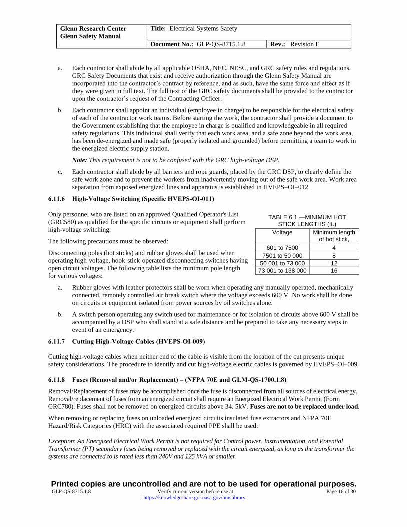
6.11.6 High-Voltage Switching (Specific HVEPS-OI-011)
Only personnel who are listed on an approved Qualified Operator's List
(GRC580) as qualified for the specific circuits or equipment shall perform
high-voltage switching.
The following precautions must be observed:
Disconnecting poles (hot sticks) and rubber gloves shall be used when
operating high-voltage, hook-stick-operated disconnecting switches having
open circuit voltages. The following table lists the minimum pole length
for various voltages:
a. Rubber gloves with leather protectors shall be worn when operating any manually operated, mechanically
connected, remotely controlled air break switch where the voltage exceeds 600 V. No work shall be done
on circuits or equipment isolated from power sources by oil switches alone.
b. A switch person operating any switch used for maintenance or for isolation of circuits above 600 V shall be
accompanied by a DSP who shall stand at a safe distance and be prepared to take any necessary steps in
event of an emergency.
6.11.7 Cutting High-Voltage Cables (HVEPS-OI-009)
Cutting high-voltage cables when neither end of the cable is visible from the location of the cut presents unique
safety considerations. The procedure to identify and cut high-voltage electric cables is governed by HVEPS–OI–009.
6.11.8 Fuses (Removal and/or Replacement) – (NFPA 70E and GLM-QS-1700.1.8)
Removal/Replacement of fuses may be accomplished once the fuse is disconnected from all sources of electrical energy.
Removal/replacement of fuses from an energized circuit shall require an Energized Electrical Work Permit (Form
GRC780). Fuses shall not be removed on energized circuits above 34. 5kV. Fuses are not to be replaced under load.
When removing or replacing fuses on unloaded energized circuits insulated fuse extractors and NFPA 70E
Hazard/Risk Categories (HRC) with the associated required PPE shall be used:
Exception: An Energized Electrical Work Permit is not required for Control power, Instrumentation, and Potential
Transformer (PT) secondary fuses being removed or replaced with the circuit energized, as long as the transformer the
systems are connected to is rated less than 240V and 125 kVA or smaller.
TABLE 6.1.—MINIMUM HOT STICK LENGTHS (ft.)
Voltage Minimum length of hot stick,
601 to 7500 4
7501 to 50 000 8
50 001 to 73 000 12
73 001 to 138 000 16

Glenn Research Center
Glenn Safety Manual
Title: Electrical Systems Safety
Document No.: GLP-QS-8715.1.8 Rev.: Revision E
Printed copies are uncontrolled and are not to be used for operational purposes. GLP-QS-8715.1.8 Verify current version before use at Page 17 of 30
https://knowledgeshare.grc.nasa.gov/bmslibrary
6.11.9 Lifting and Construction Equipment, Vehicles, or Personnel Near Exposed Energized Electrical
Parts (HVEPS-OI-012)
Personnel working near and/or using hoisting, lifting, or other construction equipment or vehicles near air-
insulated energized electrical lines or exposed terminals of electrical apparatus are subject to the minimum
safe working distances established in HVEPS–OI–012.
Construction equipment shall be separated far enough from such lines and apparatus so that equipment
failure would not result in the construction equipment approaching energized electrical facilities closer than
the established minimum safe work distance.
All equipment shall be effectively grounded (to ensure proper fault protection) when being moved or
operated in close proximity to energized lines or electrical apparatus. Consideration shall be given to
grounding the load, particularly if insulated lifting straps are in use. All such operations shall have a
dedicated observer (without any other duties) to warn equipment operators of potentially hazardous
situations and/or movements.
6.12 Personal Protective Equipment (for additional information on PPE see GSM Chapter 15)
6.12.1 Hard Hats (29 CFR 1910.135 and ANSI Z89.1)
All personnel entering high-voltage electric supply stations, power manholes, electrical cable tunnels, electrical
cable rooms, or vaults shall wear a Type I, Class E hard hat conforming to 29 CFR 1910.135 and ANSI Z89.1.
6.12.2 Eye Protection (ANSI Z87.1 and ASTM F 2178)
Safety glasses, goggles, or face shields shall be worn by an individual in any area or during any work where there is
a reasonable probability of eye injury. Eye and face protection shall meet or exceed ANSI Z87.1 Standard
“Occupational and Educational Eye and Face Protection Practice” and ASTM F 2178 “Standard Test Method for
Determining the Arc Rating and Standard Specification for Eye or Face Protective Products”.
6.12.3 Safety Shoes (ASTM F2412 and F2413)
All personnel who regularly enter high-voltage electrical supply stations, power manholes, cable tunnels, etc., shall
wear safety shoes meeting the requirements of ASTM F2412 and F2413.
6.12.4 Rubber Insulating Gloves (ASTM D 120 and ASTM F 496)
Rubber gloves used for protection against electrical shock shall meet the requirements of ASTM D 120, “Standard
Specification for Rubber Insulating Gloves” and be tested in accordance with American Society for Testing and
Materials (ASTM) F 496, “Standard Specification for Rubber Insulating Gloves in Service Care.” In addition,
ASTM F 1236, “Standard Guide for Visual Inspection of Electrical Protective Rubber Products” provides suggested
methods of pre-use inspections to ensure glove integrity.
All qualified switch persons shall have two pairs of personal rubber insulating gloves, protective leather gloves, and
a glove bag. Protective leather gloves shall always be worn over lineman-type rubber gloves and will be in
accordance with ASTM F 696, “Standard Specification for Leather Protectors for Rubber Insulating Gloves.”
Preferable glove construction shall be in contrasting two-color combinations. The contrast between the thin outer color against the inner color makes inspecting for cuts and tears easier when the glove is inflated or stretched.
Whenever the inner rubber color is visible, the pair of gloves shall be discarded.
6.12.5 Hot Sticks (ANSI/IEEE Standard 516 and 29 CFR 1910.269(j))
All hot sticks (live-line tools) shall be made of fiberglass and shall meet the requirements of 29 CFR 1910.269(j).
Field care, handling, and storage shall be per ANSI/IEEE Standard 516, Section 4. Hot sticks shall be removed from
service every 2 years and whenever required under paragraph 29 CFR 1910.269 (j)(2)(ii) for examination, cleaning,
repair, and testing.

Glenn Research Center
Glenn Safety Manual
Title: Electrical Systems Safety
Document No.: GLP-QS-8715.1.8 Rev.: Revision E
Printed copies are uncontrolled and are not to be used for operational purposes. GLP-QS-8715.1.8 Verify current version before use at Page 18 of 30
https://knowledgeshare.grc.nasa.gov/bmslibrary
6.12.6 Protective Clothing (NFPA 70E)
Personnel shall wear protective clothing as required by NFPA 70E, Table 130.7(C)(10), when performing energized
work, whether or not an Energized Electrical Work Permit (GRC780) is required. Table 130.7(C)(10) lists the
requirements for protective clothing and other protective equipment based on Hazard/Risk Category numbers 0
through 4. This clothing and equipment shall be used when working within the Arc Flash Protection Boundary.
Table 130.7(C)(11) lists examples of protective clothing systems and typical characteristics, including the degree of
protection, for various clothing. The protective clothing selected for the corresponding Hazard/Risk Category
number determined from Table 130.7(C)(9) (including associated notes) and the requirements of 130.7(C)(10) shall
have an arc rating of at least the value listed in the last column of Table 130.7(C)(11). Flame Resistant (FR) clothing
that has an arc rating based on testing defined by ASTM F 1506, “Standard Performance Specification for Flame
Resistant Textile Materials for Wearing Apparel for Use by Electrical Workers Exposed to Momentary Electric Arc
and Related Thermal Hazards”, and ASTM F 1959, “Standard Test Method for Determining the Arc Thermal
Performance Value of Materials for Clothing”, adheres to these requirements.
6.13 Equipment Safety Tests and Checks (ANSI/IEEE or NETA)
6.13.1 Tests To Be Performed Prior to Initial Energization
a. Initial energization of all new electrical equipment shall be done only in the presence of the appropriate
Government representative. Before the initial energization, feeder circuit breakers shall be checked for
proper adjustments in accordance with the manufacturer's instructions. (Molded-case circuit breakers
without solid-state trip devices are excluded from this requirement.)
b. All protective relays and other such devices shall be tested to be sure that they can operate in the range
required. Where possible, tests shall include loading in at the current transformer secondaries to validate the
circuitry as well as the device.
c. All wiring shall be checked for conformity to the design and to functional requirements.
d. All motors, cables, and switchgear shall be tested in accordance with industry standards and manufacturer's
recommendations, at voltage levels approved by the appropriate Systems Manager for the specific type of
equipment. The following industry standards shall apply:
TABLE 6.2.—TESTING STANDARDS
Equipment Standarda
Motors ANSI/IEEE or ANSI/NETAb
Cables AEIC or ANSI/NETA
Paper-insulated AEIC or ANSI/NETA
Rubber, ethylene, propylene rubber, cross-linked polyethylene-insulated ICEA or ANSI/NETA
Switches ANSI/IEEE or ANSI/NETA
Transformers ANSI/IEEE or ANSI/NETA aSee appropriate Systems Manager to determine preferred standards and methods bInterNational Electrical Testing Association
6.13.2 Circuit-Interrupting Devices
All circuit-interrupting devices shall be rated to interrupt the maximum short-circuit current that can be supplied by
the power system at the point of application of the device.
Whenever a proposal is made to add circuit-interrupting devices to the system and whenever large loads are added
or major system changes are made, the responsible engineering organization shall make system short-circuit studies
to establish the circuit-interrupting duty requirements. All such studies shall be reviewed and approved by the
responsible Facilities Division Systems Manager.

Glenn Research Center
Glenn Safety Manual
Title: Electrical Systems Safety
Document No.: GLP-QS-8715.1.8 Rev.: Revision E
Printed copies are uncontrolled and are not to be used for operational purposes. GLP-QS-8715.1.8 Verify current version before use at Page 19 of 30
https://knowledgeshare.grc.nasa.gov/bmslibrary
After any operation in which a circuit breaker opens under short circuit or fault conditions, the circuit breaker shall
be inspected, relay targets reviewed and an assessment made to determine the reason for why the breaker operation
occurred. Only after this assessment and the cause for the tripping isolated/removed can the circuit breaker be
reclosed and the circuit re-energized. The inspection and assessment shall be reviewed by a qualified operator with
support from the responsible FD System Manager.
Since fuses do not have associated relaying (targets) to provide information as to their opening the circuit, unless the
reason for the operation occurring is evident (i.e. a known overload situation), only after proper lockout/tagout has
occurred, minimum testing (meggar) accomplished and the fault situation been isolated/removed may the fuse be
replaced and the circuit restored.
6.13.3 Protective System Checks
Protective relay settings shall be coordinated to provide selective tripping. The appropriate Electrical Systems
Manager shall maintain a listing of the required settings and the frequency of periodic testing of all protective relays
in use. All HVEPS protective relays shall be checked and calibrated on a triennial basis. Every reasonable effort
shall be made to perform an end-to-end test of the relay circuitry in the process of this check, including verification
of the integrity of grounds, grounding cables, grounding resistors, and grounding transformers.
6.13.4 High-Voltage Insulation Testing
High-voltage test levels and procedures for all operating equipment shall be verified with the HVEPS Manager to
ensure that the test voltage selected and/or procedure used is based on evaluations of the type and condition of
insulation, age, damage, equipment history, and desired service, as recommended in ANSI/IEEE 95 (Insulation
Testing of Large AC Rotating Machinery with High Direct Voltage) or in NETA MTS (Maintenance Testing
Specifications).
High-voltage dielectric testing shall be performed in the presence of the DSP. Isolation, tagging, area securing, and
grounding procedures as required shall precede testing. During testing, all safety precautions listed in the respective
standard/specification shall be followed.
6.14 Experimental Equipment (GLM–QS–1700.1)
6.14.1 Safety Responsibility
Experimental electrical or electromechanical equipment that is under development, and therefore subject to frequent
modifications, can present a particular hazard to personnel. The operating and emergency procedures and attendant
hazards may change from day to day. The project manager is responsible for the safety of personnel and equipment
associated with the development of experimental apparatus. A responsible member of the team shall perform and
document periodic assessment of project/equipment hazards using, as a minimum, a Safety Permit Hazard Analysis
form, GRC923A, can be completed through the GRC Electronic Safety Permit System.
The frequency of these assessments will be determined by the initial and applicable Area Safety Committee Review
and listed as a requirement on the safety permit.
These assessments shall be used to establish correct working procedures, to identify need and use
of appropriate PPE, and to establish proper emergency procedures. Particular emphasis shall be placed on
de-energization of the equipment.
6.14.2 Experimental, Developmental, or Flight-Level Electrical/Electronic Equipment (NFPA 70E)
Following are additional guidelines for working on or near energized electrical experimental, developmental, or
flight-level electrical/electronic equipment:
a. A responsible member of the research and development team such as the Project Engineer shall establish
correct working procedures as well as proper precautions, warnings, emergency procedures, and some
approved operators list. Safety should be a recurring topic of discussion during project team meetings.
Emphasis should be placed on establishing and familiarizing project personnel with emergency procedures
to de-energize the equipment. New project personnel shall be apprised of unusual shock hazards associated

Glenn Research Center
Glenn Safety Manual
Title: Electrical Systems Safety
Document No.: GLP-QS-8715.1.8 Rev.: Revision E
Printed copies are uncontrolled and are not to be used for operational purposes. GLP-QS-8715.1.8 Verify current version before use at Page 20 of 30
https://knowledgeshare.grc.nasa.gov/bmslibrary
with the equipment. All work shall be in accordance with NFPA 70E, Standard for Electrical Safety in the
Workplace.
b. As a minimum, guards shall be provided around exposed connections energized above 50 V rms per the
NEC.
c. After de-energizing (per GRC Lockout/Tagout Program), a required minimum discharge time should be
observed and/or grounding probe(s) should be utilized to discharge circuits prior to physical contact or
circuit modifications to ensure that no residual or hazardous voltages remain.
d. Where reasonable and possible, fail safe and/or current limiting circuits should be incorporated in
equipment to minimize effects of personnel exposure to hazardous electric shock energy.
e. Temporary wiring utilized shall (1) be rated for the environment and use, (2) be routed in a reasonably neat
manner, and (3) not pose unreasonable additional hazards and (4) meet the requirements of the NEC unless
justified in writing by the GRC Fire Protection AHJ.
f. Periodic hazard assessment of project/equipment hazards and identification of appropriate PPE shall be
conducted using GRC Job Hazard Analysis form GRC239 or equivalent hazard analysis process. Faulty
equipment, frayed cords, or faulty grounding conditions shall be repaired (per LVEPS-OI-10) or
eliminated.
6.14.3 Experimental Equipment Utilizing High-Voltage Capacitor Banks
Test personnel conducting experiments in which capacitor banks with voltages above 600 V are employed shall
have total knowledge of the experiment, the circuit, and the component layout. Safety Permit Requestors shall
ensure all personnel tasked to the project are fully trained in the operating and safety procedures to be used at that
facility, including procedures to be used in the event of equipment failure. These personnel should be listed on a
Qualified Operators List (GRC580) within the GRC Electronic Safety Permit System. General guidance for use of
capacitors on power circuits is contained in NEC Article 460 and paragraph 8.8.16. Additional precautions and
procedures are as follows:
a. Each high-voltage test area shall be enclosed and protected by using gates and interlocks on the test
controls. Since capacitors and related high-voltage component faults are a source of hazardous shrapnel,
these components shall be isolated in a manner that precludes personnel injury or facility-related hazards
such as fire.
b. High-voltage warning signs shall be displayed in conspicuous locations. Flashing warning lights shall be
used to indicate that tests are in progress.
c. Shorting switches and grounding devices that normally discharge the capacitor bank shall be clearly visible
to the test operator. These devices shall be fail-safe and shall function to a safe configuration with no
electrical power.
d. A voltmeter connected across the capacitor bank shall be clearly visible to the test operator at all times. A
redundant voltmeter shall be installed at the capacitor bank.
e. Prior to touching a high-voltage component within the test area, personnel shall determine, by using a
grounding wand approved by the safety manager for the particular installation, that the capacitor bank is
fully discharged to a building ground.
f. Extreme caution shall be used on capacitor banks that are operated by dc voltages, since a dc capacitor
bank will maintain a residual voltage for extended periods.
g. Capacitors that are connected in series/parallel to form a bank shall be treated with great care, and each
capacitor terminal in a series/parallel string shall be properly shorted to ground prior to making any
changes to a test bank or circuit.

Glenn Research Center
Glenn Safety Manual
Title: Electrical Systems Safety
Document No.: GLP-QS-8715.1.8 Rev.: Revision E
Printed copies are uncontrolled and are not to be used for operational purposes. GLP-QS-8715.1.8 Verify current version before use at Page 21 of 30
https://knowledgeshare.grc.nasa.gov/bmslibrary
6.15 Training (NASA General Safety Program Requirements NPR 8715.3C)
6.15.1 Initial Training
The GRC shall develop and provide training to ensure that the purpose and function of the Electrical System Safety
program are understood by its employees per NPR 8715.3C, Chapter 3, Section 3.6.1(d). The training shall be
coordinated by the Human Capital Development Branch, with civil servant employee records maintained in the
System for Administrative, Training, and Educational Resources for NASA (SATERN) and contractor records either
stored in SATERN or the contractor’s own filing system. The training shall include the following:
ALL EMPLOYEES (on-site civil servant and contractor) shall complete SATERN Course GRC-111-11,
ELECTRICAL SAFETY - WHAT EVERYONE SHOULD KNOW. This short video provides a basic
explanation on how electricity works, what it can do to the human body and how to use electricity safely.
This video shall be viewed as part of new employee orientation.
Unqualified Employees working in machine shops, equipment rooms, test cells, etc. (Engineers,
Tradespersons, and Janitorial Crews that are not trained to work on electrical equipment but are exposed to
electrical circuits/equipment/machinery during the performance of their work) shall complete GRC-
4R1343, LC ELECTRICAL SAFETY: SHOCK PROOF-UNQUALIFIED. This video shall also be viewed
as part of new employee orientation. Note: The video does not qualify an employee. See Section 5.10 of
this chapter on how an employee becomes qualified.
QUALIFIED ELECTRICAL EMPLOYEES shall complete the following training:
o SATERN Course GRC-4R1690, GRC LOW VOLTAGE SAFETY. This course will provide
information from the Glenn Safety Manual (GSM), Chapter 8, Electrical System Safety including
the site specific Low Voltage Electrical Power System Operating Instructions (LVEPS-OI’s) an
overview of GSM Chapter 9, Lockout/Tagout and an introduction to NFPA 70E the Standard for
Electrical Safety in the Workplace. These are regulations and procedures that personnel working
as a GRC employee performing electrical tasks are required to be knowledgeable of and adhere to.
This is an instructor led class with an on-line test to be taken, through SATERN, when the
participants are ready. Tests can be scheduled to be taken off-line if personnel do not have access
to SATERN.
o SATERN Course GRC-4R1693, GRC LOW VOLTAGE SAFETY EXAM. This is the on-line test
for the above listed course. A passing test score (80 percent) shall provide the on-site certification
requirement needed for “Qualified Employees” to perform switching and operating low-voltage
equipment.
o An employee must be “Qualified” before they can become “Certified”.
Employees exposed to shock hazards shall be trained in:
o Methods of release of victims from contact with exposed energized electrical conductors or circuit
parts. SAFE RELEASE OF AN ELECTRICAL SHOCK VICTIM course GRC-111-15 is available
through SATERN
o Methods of first aid and emergency procedures, such as approved methods of resuscitation, if their
duties warrant such training. HEARTSAVER/AED TRAINING Course GRC-4R1402 is available
through SATERN. Training of employees in approved methods of resuscitation, including
cardiopulmonary resuscitation, shall be certified by the employer annually.
6.15.2 Employee Retraining
For all-of-the-above listed training requirements, retraining of employees shall be accomplished at least every 3
years, per NFPA 70E. Retraining shall also be provided for all employees whenever the employer has reason to
believe that there are deviations from or inadequacies in the employee's knowledge or use of the requirements set
forth in GSM Chapter 8.

Glenn Research Center
Glenn Safety Manual
Title: Electrical Systems Safety
Document No.: GLP-QS-8715.1.8 Rev.: Revision E
Printed copies are uncontrolled and are not to be used for operational purposes. GLP-QS-8715.1.8 Verify current version before use at Page 22 of 30
https://knowledgeshare.grc.nasa.gov/bmslibrary
Emergency retraining for those personnel required to provide emergency response (such as “The Buddy” performing
release of victim or providing CPR or AED assistance) shall be annual.
The employer shall certify that employee training has been accomplished and medical requirements (if specified in
the job classification) is being kept up to date. The certification shall contain each employee’s name and dates of
training.
7.0 RECORDS
Record Name Maintained by
Energized Electrical Work Permit GRC780 Code QSS
Training Records for Civil Servants Code CH within SATERN
Training Records for Contractors Code CH or Onsite Contractor
Facility Change Request (FCR) GRC29 Code FD
Job Hazard Analysis Form GRC239 Org or Contractor conducting task
Safety Permit Requests GRC923A Code QSS Safety Permit Program
Qualified Operators List GRC580 Code QSS Safety Permit Program
8.0 REFERENCES
Document Number Document Name
29 CFR 1910 and 1926 Public Law 91–596, Occupational Safety and Health Act (OSHA), 1970
ANSI/IEEE C2 American National Standards Institute. National Electrical Safety Code
ANSI/IEEE 95 Recommended Practice for Insulation Testing of AC Electric Machinery (2300
V and Above) With High Direct Voltage
ANSI/IEEE 516 Guide for Maintenance Methods on Energized Power Lines
ANSI Z87.1 American National Standard Occupational and Educational Personal Eye and
Face Protection Devices
ANSI Z89.1 American National Standard for Industrial Head Protection
ASTM D 120 Standard Specification for Rubber Insulating Gloves
ASTM F496 Standard Specification for In-Service Care of Insulating Gloves and Sleeves
ASTM F696 Standard Specification for Leather Protectors for Rubber Insulating Gloves and
Mittens
ASTM F 1236 Standard Guide for Visual Inspection of Electrical Protective Rubber Products
ASTM F 1506 Standard Performance Specification for Flame Resistant and Arc Rated Textile
Materials for Wearing Apparel for Use by Electrical Workers Exposed to
Momentary Electric Arc and Related Thermal Hazards
ASTM F 2178 Standard Test Method for Determining the Arc Rating and Standard
Specification for Eye or Face Protective Products
Glenn Research Center
Glenn Safety Manual
Title: Electrical Systems Safety
Document No.: GLP-QS-8715.1.8 Rev.: Revision E
Printed copies are uncontrolled and are not to be used for operational purposes. GLP-QS-8715.1.8 Verify current version before use at Page 23 of 30
https://knowledgeshare.grc.nasa.gov/bmslibrary
ASTM F 2412 Standard Test Methods for Foot Protection
ASTM F 2413 Standard Specification for Performance Requirements for Protective (Safety)
Toe Cap Footwear
ASTM F1959 Standard Test Method for Determining the Arc Rating of Materials for Clothing
ANSI/NETA ATS STANDARD FOR ACCEPTANCE TESTING SPECIFICATIONS for
Electrical Power Equipment and Systems
ANSI/NETA MTS STANDARD FOR MAINTENANCE TESTING SPECIFICATIONS for
Electrical Power Equipment and Systems
ESD TR20.20 Handbook for the Development of an Electrostatic Discharge Control Program
for the Protection of Electronic Parts, Assemblies and Equipment
HVEPS–OI–xx High-voltage Electric Power System Operating Instructions. Various dates
LVEPS–OI–xx Low-voltage Electrical Power System Operating Instructions. Various dates
GLM–QS–1700.1 NASA Glenn Safety Manual, BMS Document
NPR 8715.3C, Chapter 3.6 NASA General Safety Program Requirements Chapter 3.6
GLP-FB-8810.1 Facility Drawing File Management
NFPA 70 National Electrical Code
NFPA 70E Standard for Electrical Safety in the Workplace

Glenn Research Center
Glenn Safety Manual
Title: Electrical Systems Safety
Document No.: GLP-QS-8715.1.8 Rev.: Revision E
Printed copies are uncontrolled and are not to be used for operational purposes. GLP-QS-8715.1.8 Verify current version before use at Page 24 of 30
https://knowledgeshare.grc.nasa.gov/bmslibrary
APPENDIX A. DEFINITIONS AND ACRONYMS
Following are some key definitions related to electrical safety. Many additional related definitions are contained
within referenced documents such as the National Electrical Code (NEC) and the National Electrical Safety Code
(NESC).
Arc Flash (Flash Hazard).—A dangerous condition associated with the release of energy caused by an electric arc.
Area Clearance Process. — Documented way of communicating a disruption in service. Primarily used to notify
Affected Employees when performing lockout/tagout impacts their ability to perform their assigned tasks.
American Society of Testing and Materials (ASTM)
American National Standards Institute (ANSI)
Association of Edison Illuminating Companies (AEIC)
Authority Having Jurisdiction (AHJ) – The organization, office, or individual responsible for enforcing the
requirements of a code or standard, or for approving equipment, materials, an installation, or a procedure.
Automated External Defibrillator (AED).—this is a portable electronic device that automatically diagnoses the
potentially life-threatening cardiac arrhythmias of ventricular defibrillation and ventricular tachycardia in a patient
and is able to treat them through defibrillation.
Cardiopulmonary Resuscitation (CPR).—an emergency procedure in which the heart and lungs are made to work
by manually compressing the chest overlying the heart and forcing air into the lungs. CPR is used to maintain
circulation when the heart stops pumping.
GRC Designated High Voltage Safety Person (DSP)
Electrical Applications Safety Committee (EASC)
Electrically Safe Work Condition.—A state in which the conductor or circuit to be worked on or near has been
disconnected from energized parts, locked/tagged in accordance with established standards, tested to ensure absence
of voltage, and grounded if deemed necessary.
Electric Supply Equipment.—Equipment that produces, modifies, regulates, controls, or safeguards a supply of
electric energy.
Electric Supply Station.—Any building, room, or separate space within which electric supply equipment is located
and the interior of which is accessible, as a rule, only to qualified persons. This includes substation, transformer,
storage battery and switchgear rooms or enclosures, but does not include facilities such as pad-mounted equipment
and installations in manholes and vaults.
Enclosure.—The case or housing of apparatus, or the fence or walls surrounding an installation to prevent personnel
from accidentally contacting energized parts or to protect the equipment from physical damage.
Facilities Division (FD)
Fine Print Note (FPN).—Are not requirements and are for information purposes only.
Glenn Safety Manual (GSM)
Glenn Research Center (GRC)
Guarded.—Covered, shielded, fenced, enclosed, or otherwise protected by means of suitable covers, casings,
barriers, rails, screens, mats, or platforms to remove the likelihood of approach or contact by persons or objects to a
point of danger.
High-voltage electrical power system operating instructions (HVEPS–OI)
International Electrical Testing Association (NETA)

Glenn Research Center
Glenn Safety Manual
Title: Electrical Systems Safety
Document No.: GLP-QS-8715.1.8 Rev.: Revision E
Printed copies are uncontrolled and are not to be used for operational purposes. GLP-QS-8715.1.8 Verify current version before use at Page 25 of 30
https://knowledgeshare.grc.nasa.gov/bmslibrary
Insulated Cable Engineers Association (ICEA)
Institute of Electrical and Electronics Engineers (IEEE)
Job Hazard Analysis (JHA)
Lockout/Tagout.—Method of controlling hazardous energy sources.
Low-Voltage Electrical Power System Operating Instruction (LVEPS-OI)
Maintenance Testing Specification (MTS)
National Aerospace and Space Administration (NASA)
National Electrical Code (NEC)
National Electric Safety Code (NESC)
National Fire Protection Association (NFPA)
NASA Procedural Requirements (NPR)
Occupational Safety and Health Administration (OSHA)
Personal Protective Equipment (PPE).—Equipment designed to protect employees from serious workplace
injuries or illnesses resulting from contact with chemical, radiological, physical, electrical, mechanical, or other
workplace hazards.
Potential Transformer (PT).—A potential transformer is a special type of transformer that allows meters to take
readings from electrical service connections with higher voltage (potential) than the meter is normally capable of
handling without at potential transformer.
Qualified Operator (Switch person).—A person that has (1) Received site-specific knowledge of both the
equipment being operated and the system(s) it may impact. (2) Been trained on the maintenance and safe operation
of particular equipment including, specific voltages, and the proper PPE. (3) Received instruction on lockout and/or
tagout through the GRC Lockout/Tagout Program.
Qualified Person.—One who has skills and knowledge related to the construction and operation of the electrical
equipment and installations and has received safety training on the hazards involved. See NFPA 70E, Standard for
Electrical Safety in the Workplace, Article 110.6.
Safety and Health Division (SHeD)
Shock Hazard.—A dangerous condition associated with the possible release of energy caused by contact or
approach to live parts.
Voltage (of a circuit).—The greatest root-mean-square (effective) difference of potential between any two
conductors of the circuit concerned.
Voltage (nominal).—A value assigned to a circuit or system for the purpose of conveniently designating its voltage
class (e.g., 208Y/120 V; 2400 V; 34 500 V). The operating voltage of the system may vary above or below this
value within a range that permits satisfactory operation of equipment.
Voltage, Low.—Electric system and equipment operating at 600 V nominal or less.
Voltage, High.—Electric system and equipment operating at above 601 V nominal.

Glenn Research Center
Glenn Safety Manual
Title: Electrical Systems Safety
Document No.: GLP-QS-8715.1.8 Rev.: Revision E
Printed copies are uncontrolled and are not to be used for operational purposes. GLP-QS-8715.1.8 Verify current version before use at Page 26 of 30
https://knowledgeshare.grc.nasa.gov/bmslibrary
APPENDIX B. EXAMPLES OF SIGNS AND LABELS
WARNING
HAZARDOUS AREA
THE ELECTRICAL INSTALLATION IN THIS AREA IS RATED FOR:
CLASS 1, DIVISION 2, GROUP D
IN COMPLIANCE WITH NFPA 70
NO MODIFICATIONS MAY BE MADE TO THIS
AREA WITHOUT WRITTEN APPROVAL FROM
Robert Vanek, 3-2698.
BUILDING: 44
Sign printed on 2-10-06 To update this sign please contact the Glenn Safety Branch, e-mail: [email protected]
THE GLENN OPERATING ORGANIZATION RESPONSIBLE FOR THIS AREA IS:
Facilities Division, Systems Management and Maintenance Branch - DFI
Figure B.1.—Hazardous Area Warning Sign
Figure B.2.—Supply Station Entry Sign

Glenn Research Center
Glenn Safety Manual
Title: Electrical Systems Safety
Document No.: GLP-QS-8715.1.8 Rev.: Revision E
Printed copies are uncontrolled and are not to be used for operational purposes. GLP-QS-8715.1.8 Verify current version before use at Page 27 of 30
https://knowledgeshare.grc.nasa.gov/bmslibrary
Figure B.3.—Arc Flash Label

Glenn Research Center
Glenn Safety Manual
Title: Electrical Systems Safety
Document No.: GLP-QS-8715.1.8 Rev.: Revision E
Printed copies are uncontrolled and are not to be used for operational purposes. GLP-QS-8715.1.8 Verify current version before use at Page 28 of 30
https://knowledgeshare.grc.nasa.gov/bmslibrary
APPENDIX C. Correlation of Current in Amperes and Reaction with the Human Body
TABLE 8.1—FROM NFPA “THE ELECTRICAL
SAFETY PROGRAM” (TABLE 7.1)
Reaction of human body to electric current
Current in amperes (small body - large body)
Perception threshold (tingling sensation)
0.0007–0.0010
Slight shock—not painful (no loss of muscle control)
0.0012–0.0018
Shock—painful (no loss of muscle control)
0.0060–0.0090
Severe shock (muscle control loss & difficulty breathing)
0.0150–0.0230
0.1000–0.1000
Possible ventricular fibrillation (1-sec shock)
0.2000–0.2000
Heart muscle activity ceases 0.5000–0.5000
Tissue and organs burn 1.5000–1.5000
Note: Some persons who handle electrical
equipment mistakenly believe that their
tolerance to electric shock is related to their
ability to withstand the pain of the shock.
Actually, the lethal occurrence is a function
of the amount and duration of current
passing through the chest. Furthermore, a
lethal current may only be marginally higher
than one ranked just painful. It is cur-rent,
not voltage, that causes physiological
damage to humans. As the magnitude of the
current increases, statistically the current is
more dangerous as a cause of burns than as
a cause of heart failure. Although resistance
varies with many factors, the accepted value
for the internal resistance of the human body
is 100 ohms, and 500 ohms is used as a
reasonable expectation for contact (touch)
resistance. Several factors can impact
contact resistance such as coarseness of the
skin, area of contact, contact pressure, and
degree of wetness of the surface. These
factors can lower the overall resistance and
allow increased current to flow.
Example: Utilizing Ohm’s Law
(Hand contact + internal + foot contact = Total resistance)
500 ohms + 100 ohms + 500 ohms = 1100 ohms
120 volts/1100 ohms = 0.1091 amps
This amperage, based on the table above, is of sufficient value to cause ventricular fibrillation, which could be fatal.
Note that this is based on only 120 V, which we all use on a daily basis. Wet hands or breaks in the skin would
decrease the resistance more and increase the current through the body.

Glenn Research Center
Glenn Safety Manual
Title: Electrical Systems Safety
Document No.: GLP-QS-8715.1.8 Rev.: Revision E
Printed copies are uncontrolled and are not to be used for operational purposes. GLP-QS-8715.1.8 Verify current version before use at Page 29 of 30
https://knowledgeshare.grc.nasa.gov/bmslibrary
APPENDIX D. “WHEN IS THE BUDDY SYSTEM REQUIRED DURING ELECTRICAL
APPLICATIONS”
Who’s your “Buddy”? Someone working with or perhaps observing the work of another
employee, when the task is potentially hazardous. The main benefit of the system is improved
safety; to be able to prevent the other from becoming a casualty in a crisis situation where
minutes can mean the difference between life and death.
When is a “Buddy” required? When personnel are exposed to an electrical hazard. See
electrical hazard definition below.
Electrical Hazard. A dangerous condition such that contact or equipment failure can result in
electric shock, arc flash burn, thermal burn, or blast.
Shock Hazard. A dangerous condition associated with the possible release of energy
caused by contact or approach to energized electrical conductors or circuit parts. A shock
hazard is generally considered to exist under normal conditions when a person is exposed
to a voltage of 50 volts or greater.
NFPA 70E Informative Annex K - General Categories of Electrical Hazards
K.2 Electric Shock.
Approximately 30,000 nonfatal electrical shock accidents occur each year. The National
Safety Council estimates that about 1000 fatalities each year are due to electrocution,
more than half of them while servicing energized systems of less than 600 volts.
Electrocution is the fourth leading cause of industrial fatalities.
When is a “Buddy” required? Breaking of the restricted approach boundary by reach or tool
requires both proper shock PPE and the presence of a “Buddy”. Also removal of bolted
panelboard covers exposing energized parts shall require the presence of a Buddy. Arc flash PPE
may already have been required when the Limited Approach Boundary was crossed.
Restricted Approach Boundary; An approach limit
at a distance from exposed energized electrical
conductors or circuit parts within which there is an
increased likelihood of electric shock for personnel.
Only “qualified” employees may cross this boundary.
The Limited Approach Boundary is accessible to
unqualified employees when escorted by a qualified
employee. The figure to the right represents boundary
values when exposed to voltages of 151V – 750VAC.
208/120 V PANELBOARD
Restricted Approach
1 ft.
Limited Approach
3 ft.
Boundary increases for voltages above 750VAC,
see Table 130.4(D)(a) in NFPA 70E
Cover opened
or removed
with exposed
energized parts

Glenn Research Center
Glenn Safety Manual
Title: Electrical Systems Safety
Document No.: GLP-QS-8715.1.8 Rev.: Revision E
Printed copies are uncontrolled and are not to be used for operational purposes. GLP-QS-8715.1.8 Verify current version before use at Page 30 of 30
https://knowledgeshare.grc.nasa.gov/bmslibrary
When is a “Buddy” not required? Once an Electrically Safe Work Condition (ESWC) is
established, shock and arc flash PPE are no longer required nor is the need (electrically) for a
“Buddy” required.
Electrically Safe Work Condition (ESWC). A state in which an electrical conductor or circuit
part has been disconnected from energized parts, locked/tagged in accordance with established
standards, tested to ensure the absence of voltage, and grounded if determined necessary.
Establishing an ESWC is the only work procedure that ensures that an electrical injury cannot
occur. Until the ESWC is established (including verification of the loss of potential), an
unacceptable risk of injury from exposed energized electrical conductors or circuit parts exists
and a Buddy is required.
What Does A “Buddy” Need To Know?
NFPA 70E 110.2(C) Emergency Response Training;
Contact Release. Employees exposed to shock hazards shall be trained in methods of safe
release of victims from contact with exposed energized electrical conductors or circuit parts.
First Aid, Emergency Response and Resuscitation
Employees responsible for responding to medical emergencies
shall be trained in
a) First aid and emergency procedures.
b) Cardiopulmonary resuscitation (CPR).
c) In the use of an automated external defibrillator (AED), if an
employer’s emergency response plan includes the use of this device.
NOTE: Emergency Response Retraining shall occur annually.
Questions? Contact the Safety and Health Division (SHeD) 3-3016 or 3-3019
Call 911 (from inside line)
or from an outside line or
cell phone
At Lewis Field
216-433-8888
At Plum Brook
419-621-3222
The “Buddy” becomes exposed to a shock hazard when trying to free the victim.
They also need to be trained and provided the proper PPE to perform the release
of the electric shock victim safely.
Retraining on the safe release of electrical shock victims, as of the 2015 version
of NFPA 70E, shall occur annually.
SATERN Course GRC-111-15
“SAFE RELEASE OF AN ELECTRICAL SHOCK VICTIM” is available on
line as a means of providing this training