ELECTRICAL AND ELECTRONIC ENGINEERING DEPARTMENT
108
1988 ELECTRICAL AND ELECTRONIC ENGINEERING DEPARTMENT GRADUATION PROJECT (EE 400) i. SATELLITE SPREAD SPECTRUM COMMUNICATION SUPERVISED BY: PREPARED BY: PROF. DR. FAHRETTIN M. SADIGOGLU SYED AMIR ANJUM 931320 X MARCH. 1997
Transcript of ELECTRICAL AND ELECTRONIC ENGINEERING DEPARTMENT

1988
ELECTRICAL AND ELECTRONIC ENGINEERING
DEPARTMENT
GRADUATION PROJECT
(EE 400)
i. SATELLITE SPREAD SPECTRUM COMMUNICATION
SUPERVISED BY: PREPARED BY:
PROF. DR. FAHRETTIN M. SADIGOGLU SYED AMIR ANJUM
931320
X MARCH. 1997


TABLE OF CONTENTS
INTRODUCTION 1-2
1.1 Elements of Satellite Communication 3-4 ?
1.2 Satellite Frequency Bands 4-7 \A
1.3 Satellite Systems 7-9 "'(
1.4 Transmission 9-10 ~
1.5 Reception 10-11 ,o
1.6 Modulation 11-13 n
2.1 Communications Satellite, Orbit and Description 14 I LA_
2.2 Orbital Period and Velocity 15-21 /ts
2.3 Adventages of Geostationary Orbit 21-22 <),'\
2.4 Use of Inclined Orbit 22-23 -»
2.5 Placement of a Satellite in a Geostationary Orbit 23-25~ •..

3.1 Fundamentals of Spread Spectrum 26-27 r;f
3.2 Pseudo-Noise Sequence 27-29 J,.b
3.3 Properties ofMaximum-Lenght Sequences 29-32 7.--i
3.4 Direct-Sequence Spread Consemt 32-33~0
3.5 Model for Analysis 33-34 3 \
3.6 Biphase Modulations 35---- ~ r
3.7 Quadriphase Modulation 36 ~
3.8 A Notion of Spread Spectnun 37-40~\,\
4.1 Frequency-Hop Spread Spectrum
4.2 Slow-Frequency Hopping (Transmitter)
4.3 Slow-Frequency Hopping (Receiver)
4.4 Fast-Frequency Hopping
41-42 ~:'.\
42-43 °Ji
43-46 .,~
46-47 'v\ t
5.1 Time-Hopping 48-49 '-' 1:)
5.2 The Time Hopped Signal 49-50 t,1,1
('
5.3 Chirp Spread Spectrum 51 \,\'>
5.4 Comparision of Modulation Methods 51 l1 b
5.5 Direct-equence (PN) Systems 51-52.'ib
( Adventages and Disadventages)
5.6 Frequency-Hopping (FH) Systems 52 v\\
(Adventsges and Disadventages)
5.7 Time-Hopping (TH) Systems 52-53 !-\,,.
(Adventages and Disadventages)
5.8 Hybird Spread-Spectrum Systems 53-54 v,'b
5.9 Example of PN/FH System 54 · IJ\'ti

6.1 Application of Spread Spectrum to Communications 55-58 ~,
6.2 Examples of Spread Spectrum Systems 58-59 ~ 1
6.3 Code-Division Multiple Access 59-60 c; >
6.4 Summary and Discussion 60-63 s "1
CONCLUSION 64
REALIZATION OF PROJECT
APPENDIX A (FOR FIGURES)
REFERENCES AND BIBLIOGRAPHY
ABBREVIATIONS

IJ It is a great pleasure for me to thanks first of all my parents who
provided the support and motivation necessary to start and complete my
studies.
In preparing this graduation project, I have been guided by. the
expertise of my teacher Mr. Prof. Dr. Fahrettin M. SADIGOGLU and it is
also pleasure to acknowledge the enthusiastic support and assistance given to
me by him in realizing the project.
I would like to acknowledge the following students and express my
smcere appreciation for their helpful suggestions, criticisim and
encouragement.
Azeem Baig Ghazi
Muhammad Amir Aslam
Hyder Ali
Umar Farooq Hussain
Asif Iqbal
Farhan Aftab
Finally, I wish to thank my friend, Tijen Kulah, for her patience and
extra care in typing this project. Needless to say without all the above help
and support, the writing and production of this project would not have been
possible.
Syed Amir Anjmn ..
INTRODUCTION
Spread spectrum is not new. It was developed primarily by the
military after world war II. Its use has been restricted to military
communications applications because it is a secure communications
techniques that is essentially immune to jamming. In the mid-1980' s, the
FCC authorised use of SS in civilian application.
Spread spectrum is a technique whereby an already modulated
signal is modulated a second time in such a way as to produce a waveform
which interferes in a barely noticeable way with any other signal (this type
of modulation has been discussed in chap.3) operating in the same
frequency band. Thus a receive tuned to receive specific AM or FM
broadcast would probably not notice the presence of a spread spectrum
signal operating over the same frequency band. Similarly, the receiving of
the spread spectrum signal would not notice the presence of the AM or
FM signal. Thus, we say that interfering signals are transparent to
interfering signals. The different types of spread spectrum modulation
techniques have been discussed in chap. 3, 4 and 5.
The widest application at this time is its use in military
communications systems where spread spectrum serves two functions. The
first is that it allows a transmitter to transmit a message to a receiving with
not the message being detected by a receiving for which it is not intended.
The second major application of spread spectrum is found, when, as a
matter of fact, it tums out not to be possible to conceal the transmission.
1

In the conunercial communications field spread spectrum has many
applications, a major application being the transmission of a spread
spectrum signal on the same carrier frequency as an already existing
/ microwave signal. By communicating in this manner over additional i l signals can be transmitted over the same band thereby increasing the -:t of
users. The addition, spread spectrum is used in satellite communications
and is being considered for use in local area networks.
2

CHAPTER]
1.1. ELEMENTS OF SATELLITE COMMUNICATION
The unique feature of communications satellites is their ability to
simultaneously link all users on the earth's surface, thereby providing
distance insensitive point-to-multipoint communications. This capability
applies to fixed terminals on earth and to mobile terminals on land, in the
air, and at sea. Also, with satellites, capacity can be dynamically allocated
to users who need it. These features make satellite communications
systems unique in design. This chapter serves as an overview of satellite
communication. A satellite with a circular equatorial orbit at a correct
altitude of 35,786 km would make one revolution every 24 h: that is, it
would rotate at the same angular velocity as the earth. And observer
looking at such a geostationary satellite would see it hanging at a fixed
spot in the sky. Clarke showed that three geostationary satellites powered
by solar energy could provide world-wide communications for all possible
types of services. Clarke's vision became a reality 20 years later when the
International Teleconununications Satellite Organization (INTELSAT),
established in 1964, launched the Early Bird (INTELSAT) in April 1965.
Many INTELSAT satellites have been launched or are in the planning
stages, ranging from instnunents with a small capacity (240 voice circuits
or one television channel) to those with a huge capacity (40,000 voice
circuits for INTELSAT VI) and covering three regions-the Atlantic,
Pacific, and Indian oceans. Fig.1.1.(See Appendix A).
3

Table 1.1. Electromagnetic frequency spectrum
30 -300 GHz 10 - 10
Wavelenaht tm 10 - 10 10 - 10
300 kHz - 3 11:Hz 10 - 10 3 - 3011:Hz 10 - 10 30 - 30011:Hz 10 - I 300 11:Hz - 3 GHz I -10 3 - 30 GHz 10 - 10
10-IOGHz 3 X 10 - 3 X 10
1.2. SATELLITE FREQUENCY BANDS
Communications system employ the electromagnetic frequency
spectnun shown in Table 1.1. The frequencies used for satellite
communications are allocated in superhigh-frequency (SHF) and extremely
high-frequency (EHF) band which are broken down into subbands as
summarised in Table 1.2. Spectnun management is an important activity
that facilitates the orderly use of the electromagnetic frequency spectrum
not only for satellite communications but for other telecommunications
applications as well. This done under the auspices of the International
Telecommunications Union (ITU) which is a specialized agency of the
United Nations (UN).
4

Table 1.2. Satellite Frequency Spectrum
Frequency Band Range (GHz) L 1 - 2 s 2-4 C 4-8 X 8 - 12 Ku 12 - 18 K 18 - 27 Ka 27 - 40 Millimetre 40 - 300
The frequency bans allocated by W ARC- 79 for satellite
communications involve 17 service categories ( although some of them
represent special subcategorise), as listed in Table 1.3, and three
geographic regions; regionl which includes Europe, Africa, the USSR, and
Mongolia; region 2 which includes North an South America and
Greenland; and region 3 which includes Asia ( except the USSR and
Mongolia), Australia, and Southwest Pacific. Tables 1. 4 and 1. 5 show the
W ARC-79 frequency allocations for fixed satellite services (FSS) and
broadcasting satellite service (BSS).
Table 1.3. Satellite Services
Fixed Intersatellite Mobile Land mobile Maritime mobile Aeronautical mobile Broadcasting Earth exploration Sgace research
Meteorological Space operation Amateur Radiodetermination Radionavigation Aeronautical radionavigation Maritime radionavigation Standard frequency and time signal
5

Table 1.4. Frequency allocation for fixed satellite service
Frequency Frequency ran e GHz Restrictions ran e GHz Restrictions 2.5 - 2.535 ln,2d,3d 18.1-21.2 d 2.535 - 2.655 ln,2b,3n 27 -27.5 ln,2u,3u 2.655 - 2.690 ln,2b,3u 27.5-31 u 3.4 - 4.2 d 37.5 - 40.5 d 4.5 - 4.8 d 42.5 - 43.5 u 5.725 - 5.85 lu,2n,3n 47.2 - 49.2 u 5.85 - 7.075 u 49.2 - 50.2 u 7.25 - 7.75 d 50.4-51.4 u 7.9-8.4 u 71 - 74 u 10.7-11.7 lb,2d,3d 74 - 75.5 u 11.7 - 12.3 ln,2d,3n 81 - 84 d 12.5 - 12.7 lb,2n,3d 92 - 95 u 12.7 - 12.75 lb,2u,3d 102 - 105 d 12.75 - 13.25 u 149 - 164 d 14 - 14.5 u 202 - 217 u 14.5 - 14.8 u 231 - 241 d 17.3-17.7 u 265 - 275 u 17.7-18.1 b
1, Region 1; 2, Region 2; 3, Region 3; u, uplink ( earth to space); d,
downlink (space to earth); n, not allocated; b, bidirection.
Uplink limited to BSS feeder links.
Intended for but not limited to BSS feeder links.
6

Table 1.5. Frequency allocations for broadcasting satellite service
Frequency range (GHz) Restriction 0.62 - 0.79 2.5 - 2.69 11.7-12.1 12.1 - 12.2 12.2 - 12.5 12.5 - 12.7 12.7 - 12.75 22.5 - 23 40.5 - 42.5 84 - 86
t C
1, 3 only
1, 2 only 2, 3c only 3c only 2, 3 only
t, Television only; c, community reception only; 1, region; 2, region 2; 3,
region 3.
1.3. SATELLITE SYSTEMS
A satellite system consists basically of a satellite in space which
links many earth stations on the ground, as shown schematically in Fig.
1.2. (See Appendix A).The user generates the based band signal which is
routed to the earth station through the terrestrial network. The terrestrial
network can be a telephone switch or a dedicated link to earth station. At
the earth station the baseband signal is processed and transmitted by a
modulated radio frequency (RF) carrier to the satellite. The satellite can be
through of a large repeater in space. It receives the modulated RF carriers
in its uplink (earth-to-space) frequency spectrum from all the earth stations
in the network, amplifies these carriers, and retransmits them back to the
earth in downlink (space-to-earth) frequency spectnun which is different
7

from the uplink frequency spectrum in order to avoid interference. The
receiving earth station processed the modulated RF carrier down the
baseband signal which is sent through the terrestrial network to the user.
Most commercial communications satellites today utilize a 500-Mhz
bandwidth on the uplink and a 500-Mhz bandwidth on the downlink. The
most widely used frequency spectrum is the 6/4-Ghz band, with an uplink
of 5.725 to 7.075 Ghz and a downlink of 3.4 to 4.8 Ghz. The 6/4-Ghz
band for geostationary satellites is becoming overcrowded because it is
also used by common carriers for terrestrial microwave links. Satellites are
now being operated in the 14/12-Ghz band using an uplink of 12. 7 5 to
14.8 Ghz and a downlink of either 10.7 to 12.3 Ghz or 12.5 to 12.7 Ghz.
The 14/12-Ghz band will be used extensively in the future and is not yet
congested, but one problem exists-rain, which attenuates 14/12-Ghz
signals much more than it does those at 6/4 Ghz.
The typical 500-Mhz satellite bandwidth at the 6/4 and 14/12-Ghz
bands can be segmented into many satellite transponder bandwidths. For
example eight transponders can be provided, each with a nominal
bandwidth of 54 Mllz and a center-to-center frequency spacing of 61
Jv1Hz. Modem communications satellites also employ frequency reuse to
increase the number of transponders in the 500 Mllz allocated to them.
Frequency reuse can be accomplished through orthogonal polarizations
where one transponder operates in one polarization (e.g., vertical
polarization) and a cross- polarized transponder operates in the orthogonal
polarization ( e.g., horizontal polarization).
We will now take a look at an earth station that transmits
information to and receives information from a satellite. Figure l.3(See
Appendix A). shows the functional elements of a digital earth station.
Digital information in the from of binary digits from the terrestrial network
8

enters the transmit side of the earth station and is then processed (buffered,
multiplexed, formatted, ect.) by the baseband equipment so that these
forms of information can be sent to the appropriate destinations. The
presence of noise and the nonideal nature of any communication channel
introduce errors in the information being sent and thus limit the rate at
which it can be transmitted between the source and the destination.
If the received information does not meet the error rate requirement,
error-correction coding performed by the encoder can often be used to
reduce the error rate to the acceptable level by inserting extra digits into
the digital stream from the output of the baseband equipment. These extra
digits carry no information but are used to accentuate the uniqueness of
each information messages.
1.4. TRANSMISSION
In order to transmit to baseband digital information over a satellite
channel that is a bandpass channel, it is necessary to transfer the digital
information to a carrier wave at the appropriate bandpass channel
frequency. This technique is called digital carrier modulation The function
of the modulator is to accept the symbol stream from the encoder and use
it to modulate and intermediate frequency (IF) carrier. In satellite
communications the IF carrier frequency is chosen at 70 MHz for a
communication channel using a 36-MHz transponder bandwidth and at
140 MHz for a channel using a transponder bandwidth of 54 or 72 MHz.
A carrier wave at an intermediate frequency rather than at the satellite RF
uplink frequency is chosen because it is difficult to design a modulator that
works at the uplink frequency spectrum ( 6 or 14 Ghz, as discussed
previously). For binary modulation schemes, each output digit from the
9

encoder is used to select one of two possible waveforms. For M-ary
modulation schemes the output of the encoder is segmented into sets of k
digits, where M=2k and each digit set or symbol is used to select one of
the M waveforms. For example, in one particular binary modulation
scheme called phase-shift keying (PSK), the digit 1 is represented by the
waveforms sl(t)= A cos wOt and the digit O is represented by the
waveform sO( t )= - A cos wOt. where wO is the intermediate frequency.
The modulated IF carrier from the modulator is fed to the
upconverter, where its intermediate frequency wO is translated to the
uplink RF frequency, Wu in the uplink frequency spectnun of the satellite.
This modulated RF carrier is then amplified by the high-power amplifier
(HP A) to a suitable level for transmission to the satellite by the antenna.
1.5. RECEPTION
On the receive side the earth station antenna receives the low-level
modulated RF carrier in the downlink frequency spectnun of the satellite.
A low-noise amplifier (LNA) is used to amplify this low-level RF carrier
requirement. The downconverter accepts the amplified RF carrier from the
output of the low-noise amplifier and translates the downlink frequency
wa to the intermediate frequency wo. The reason for downconverting the
RF frequency of the received carrier wave to the intermediate frequency is
that it is much easier to design the demodulator to work at 70 or 140 Mllz
than at a downlink frequency of 4 or 12 GHz. The modulated IF carrier is
fed to the demodulator, where the information is extracted. The
demodulator estimates which of the possible symbols was transmitted
based on observation of the received IF carrier. The probability that a
symbol will be correctly detected depends on the carrier-to-noise ratio of
10

the modulated carrier, the characteristics of the satellite channel, and the
detection scheme employed. The decoder performs a function opposite
that of the encoder. Because the sequence of symbols recovered by the
demodulator may contain errors, the decoder must use the uniqueness of
the redundant digits introduced by the encoder to correct the errors and
recover information-bearing digits. The information stream is fed to the
baseband equipment for processing for delivery to the terrestrial network.
1.6. MODULATION
In digital modulation, the performance of the modulator is measured
in terms of the average probability of bit error, or the bit error rate as it is
often called. The binary information, which consists of sequences of 1 and
0 digits, can be used to modulate the phase, frequency, or amplitude, we is
the carrier frequency, and 0 is the carrier phase. To transmit the binary
digit or bit 1, 0 is set to O rad, and to transmit the bit 0, 0 is set to n
radians .. Thus 1 is represented by the waveform A cos wet, and O is
represented by the waveform A cos ( wet + n ) = - A cos wet. This type of
discrete phase modulation is called phase-shift keying (PSK). Similarly, 1
can be transmitted by using the waveform A cos wit and O transmitted by
using the waveform A cos wzt, where w1:;t:w2. This type of digital
modulation is called frequency shift keying (FSK), where two waveforms
at different carrier frequencies w 1 and w2 are used to convey the binary
information. The problem with digital modulation is that sometimes the
binary digit 1 is transmitted but the demodulator decodes it as a 0, or vice
versa, because of perturbation of the carrier by noise; this results in bit
errors in the demodulations of the binary information. The average
11

probability of the bit error P b is a convenient measure of the performance
of the demodulator and is a fimction of the ratio of the energy per bit E b is
the energy of the carrier during a signalling interval or bit duration T b and
N 0/2 is the noise power spectral density. When the baseband information
is transmitted at a rate of R bits per second, the bit duration is simply T b
= I /R seconds, and this is also the signalling interval of the waveform that
represents a particular bit. For example, in PSK modulation,
Sl(t) = A COS Wet
S2(t) = -A COS Wet
0 :S t :S Tb
0 :S t :S Tb
where SI ( t) represents I and S2( t) represents O. By definition we have
Eb= f s21 (t) dt = f s22 (t) dt = f A2 cos2 wet dt
Note that Eb ~ A2Tb/2 when We > 2n!Tb. The quantity Eb/NO can be
related to the average carrier power C, and the noise power N measured
within the receiver noise bandwidth B. By definition, the average carrier
power is
C = I/Tb f E [ S2 (t) ] dt
where S( t) is the carrier waveform during the signalling interval Tb and
E [ •] is the expected value. If all the carrier waveforms have identical
energy Eb during any signalling interval, then
12

C = Eb I Tb
Recall that the power spectral density of noise is N0/2 and that the noise
bandwidth is B. Hence the noise power measured within the noise
bandwith for both positive and negative frequency is
N=NoB
Therefore it is seen that the ratio of the energy per bit to the noise density
can be expressed as
Eb/No= CTb I (NIB)= TbB (C/N)
where C/N is the average carrier-to-noise ratio. In satellite
communications, it is the quantity C/N that is directly evaluated. Once the
CIN is known and the bandwidth of the receiver is selected, Eb/NO can be
calculated, as well as the average probability of bit error Pb which is a
function of Eb/NO.
13

CHAPTER2
2.1. COMMUNICATIONS SATELLITE:
ORBIT AND DESCRIPTION
This chapter addresses the orbital mechanics of communications
satellites, together with their construction, especially in relation to a
geostationary satellite that appears to an observer on earth to be hanging
perfectly still at one spot in the sky. But this is all relative-an observer in
space sees a geostationary satellite orbiting the earth at a speed of
11,068.8 km/h. At this velocity the satellite makes one revolution around
the earth in exactly the same amount of time its takes the earth to rotate
once on its axis. Since the only great circle that is moving exactly parallel
to the direction of the earth's rotation is the equator, the geostationary
orbit lies in the equatorial plane at a distance of approximately 42,164 km
from the earth's centre. A satellite that has a 24-h nonequatorial orbit is
called a synchronous satellite.
Why use a geostationary satellite? Because it is stationary relative to
a point on earth, there is no requirement for a tracking antenna and the cost
of the space and earth segments is much less than for lower-altitude
satellite systems. This is the principle advantage.
14

2.2. ORBITAL PERIOD AND VELOCITY
The motion of a satellite orbiting the earth can be described by
Newton's laws of motion and the law of gravitation. Consider the earth as
having a mass of Ml and the satellite a mass of M2 at distance Rl and R2
from some inertial origin as shown in Fig.2. l(See Appendix A). From
Newton's second low of motion, which says that a force acting on a body
is equal to the product of its mass and its acceleration, the forces F 1 on the
earth and F2 on the satellite are given by
F1 = rm d2 n I dt"
F2 = mz d2 rz I df
Also according to Newton's law of gravitation, the attractive force
between ant two bodies is directly proportional to the product of their
masses and inversely proportional to the square of the distance between
them. Thus
F 1 = - F 2 = g m 1 mz I r2 ( r I r)
where g is the universal gravitational constant. From the above three
equations we deduce that
d2 rt I df = g rnz I r2 (r/r)
d2 rz I dt2 = -g mi I r2 (r/r)
15

submitting r = n - n gives
d2 r/dt2 = -g (1111+1112) r/r3
= -µ r I r3 (2.1)
where µ = g (ml + 1112) :::::: gml , since the mass of the satellite is negligible
compared to that of the earth. The value gml is given in as µ :::::: gml =
3.986013 x 10 s km3/S2. Equation (2.1) is known as the two body equation
of motion in relative from. It describes the motion of a satellite orbiting the
earth.
A satellite orbit is either elliptical or circular, as shown in
Fig.2.2(See Appendix A), and its characteristics are governed by Kepler's
laws:
First law: The orbit of a satellite is an ellipse with the centre of the
earth at one focus.
Second law: The line joining the centre of the earth and the satellite
sweeps over equal areas in equal time intervals.
Third law: The squares of the orbital periods of two satellites have
the same ratio as the cubes of their mean distances from the centre
of the earth.
In Fig:2.2(See Appendix A) the following notation is used:
r = distance of satellite from primary focus F which is the centre of
the earth.
v = true anomaly, measured from primary focus Fin the direction of
motion from the perigee to the satellite position vector r.
a= semimajor axis of ellipse
16

b = semiminor axis of ellipse
e = eccentricity
Ea = eccentric anomaly defined by an auxiliary circle of radius a
having the centre O of the ellipse as origin.
p = semiparameter
q = perigee distance, the point of the orbit closest to focus F
Q = apogee distance, the point of the orbit farthest from the focus F
(not shown in Fig.2.2).
The first law is stated as the polar equation of the ellipse with origin at the
primary focus. By using pie = r/e + r cos v, we have
p = r ( 1 + e cos v ) (2.2)
The second law, the law of areas, can be derived by finding the cross
product of the position vector rand the acceleration vector d'r/df given by
Newton's law in (2.1):
r x (d2r/dt2) = r x (-µ r/ r3) (2.3)
With the help of the first law the integral of the above cross-product yields
I r x d r/dt I = r2 dv I dt = -Jµ p (2.4)
17

which means that the area swept out by the radial vector r in an
infinitesimal time is constant. Rewriting the above equation and using the
fact that p = a (1 - e-), as seen in Fig.2.2(See Appendix A), we have
r2dv = ..j7:p dt =.Jµa(l-e2)dt (2.5)
By using the relations
cos v = (cos Ea -e) I (l-e cos Ea) (2.6a)
and
sin v = .JI- e2 sin Ea I (l-e cos Ea) (2.6b)
we obtain, by differentiating (2.6a),
-sin v dv = dEa I (1 - e cos Ea)2[ -sin Ea (1-e cos Ea) -e sin Ea (cos Ea -e)]
and, with the substitution of (2. 6b ),
.JI - e2 sin Ea dv I (l-e cos Ea)= dEa I (l-e cos Ea)2 (l-e2)sin Ea
dv = .JI - e2 I (l-e cos Ea) dEa
18

By using the relation r = a (1 - e cos Ea) and dv in the expression of r2 dv
in (2.5), we obtain
a2 (1-e cos Ea) .JI - e2 dEa = .J µa (1 - e2) dt
or
(1- e cos Ea) dEa = 5 I a 3;2 dt
The integral of this equation is called Kepler's equation:
M = Ea -e sin Ea= 5 I a 3/2 (t - to) (2.7)
M is called the mean anomally and increases at a steady rate n, known as
the mean angular motion:
n= 5 /a312 (2.8)
To obtain the third law, the orbital period law, set Ea= 2rc and T = t-tO for
the satellite period:
2rc = 5 I a 3;2 T
19

T = 2n m12 I ~ (2.9)
or
Note that the circular orbit is just a special case of the elliptical orbit
where a = b = r.
To derive the orbital velocity of the satellite, we find the scalar
product of the acceleration d2r/dt2 in (2 .1) and dr/dt, obtaining
dr/dt • d2r I dt2 = - µ I r3 ( dr I dt-r) = - µ I r2( dr/dt)
The integral of this equation is
1/2 (dr/dt • dr/dt) = 1/2 v2 = µ /r +C = 1/2[ (dr/dt)2 + (r dv/dt)"]
where V is the velocity. At the perigee dr/dt = 0 and r = q, hence from
(2.4)
r dv/dt = -Jµ p Ir= -Jµ p lq
and
µ /q + C = µp /2q2
C = µ/q (p/2q- l) = µ/ a(l-e )[ a (l-e2)/2a (1-e )-1]
=-µI 2a
Hence the orbital velocity is given by
V = J µ(2 I a - 1/ a) (2.10)
The orbital period of the satellite is expressed in terms of mean solar
time; it is not as accessible to measurement as another kind of time which
is determined from the culminations of stars-siderial time. A sidereal day is
20

defined as the time required for the earth to rotate once on axis relative to
the stars.
A sidereal day is measured as 23 h, 56 min, and 4.09 s of mean
solar time. A satellite with a circular orbital period of one sidereal day is
called a synchronous satellite and has an orbit radius of
a= ( T .Jµ° 12n) 213 = 42,164.2 km
If the synchronous orbit is over the equator and the satellite travels
in the same direction as the earth's surface, the satellite will appear to be
stationary over one point on earth. This type of orbit is over the equator
and the satellite travels in the sane directions as the earth's surface, the
satellite will appear to be stationary over one point on earth. This type of
orbit is called a geostationary orbit. By taking the mean equatorial radius
of the earth to be 6378.155 km , the distance from the satellite to the
subsatellite point is found to be 42,164.2 - 6378.155 = 35,786.045 km for
a geostationary orbit. (The subsatellite point is the point where the equator
meets the line joining the centre of the earth and the satellite.)
The geostationary orbit is now employed for most commercial
satellites because of the following advantages:
2.3. ADVANTAGES OF GEOSTATIONARY ORBIT
1. The satellite remains stationary with respect to one point on earth;
therefore the earth station antenna is not required to track the satellite
periodically. Instead, the earth station antenna beam can be accurately
aimed toward the satellite by using the elevation angle and the azimuth
angle (Fig.2.3) (See Appendix A). This reduces the station's cost
considerably.
21

2. With a 5° minimum elevation angle of the earth station antenna, the
geostationary satellite can cover almost 38% of the surface of the earth.
3. Three geostationary satellites (120° apart) can cover the entire surface
of the earth with some overlapping, except for the polar regions above
latitudes 76°N and 76°S, assuming a 5° minimum elevation angle.
4. The Doppler shift caused by a satellite drifting in orbit (because of the
gravitational attraction of the moon and the sun) is small for all the earth
stations within the geostationary satellite coverage. This is desirable for
many synchronous digital systems.
2.4. USE OF INCLINED ORBIT
To cover the polar regions and to provide higher elevation angles for
earth stations at high northem and southern latitudes, inclined orbits such
as the one in Fig. 2.4(See Appendix A). can be used. The disadvantages of
an inclined orbit are that the earth station antenna must acquire and track
the satellite and the necessity for switching from a setting satellite to a
rising satellite. This handover problem can be minimized by designing the
orbit so that the satellite is over a certain region for a relatively long part of
its period.
The satellite visibility for a station above 60° latitude with an
antenna elevation greater than 20° is between 4.5 and 10.5 h.
Although geostationay satellite appears to be stationary in its orbit,
the gravitational attraction of the moon and to a leser extend that of the sun
cause it to drift from its stationary position and the satellite orbit tends to
become inclined at a rate of about IO /year. Also, nonuniformity of the
22

earth's gravitational field and the radiation pressure of the sun cause the
satellite to drift in longitude.
Stationkeeping is therefore required to maintain the position of a
satellite accurately so that satellites in a geostationary orbit do not drift
close together and cause adjacent satellite interference. North-south
stationkeeping is required to prevent a drift in latitude, and east-west
stationkeeping is needed to prevent a drift in longitude.
2.5. PLACEMENT OF A SATELLITE IN A GEOSTATIONARY
ORBIT
The placement of a satellite in a geostationary orbit involves many
complex sequences and is shown schematically in Fig.2.5(See Appendix
A). First the launch vehicle ( a rocket or a space shuttle) places the satellite
in an elliptical transfer orbit whose apogee distance is equal to the radius
of the geosynchronous orbit (42,164.2 km). The perigee distance of the
elliptical transfer orbit is in general about 6678.2 km (about 300 km above
the earth' surface). The satellite is than spin-stabilized in the transfer orbit
so that the ground control can communicate with its telemetry system.
When the orbit and attitude of the satellite have been determined exactly
and when the satellite is at the apogee of the transfer orbit, the apogee kick
motor is fried to circularized the orbit. This circular orbit, with a radius of
42,164.2 km, is a geostationary orbit if the launch is carried out at 0°
latitude (i.e., at the equator).
The velocity at the perigee and apogee of the transfer orbit can be
calculated from (2.10):
V = ) µ(2 Ir - 1/ e)
23

At the perigee r = 6678.2 km, a =(6678.2 + 42,164.2)/2 = 24,402.2 km,
and the velocity is
Vp = 10.15 km/s
At the apogee r = 42,164.2 km, hence the velocity is
Va= 1.61 km/s
Since the velocity in asynchronous orbit (r =a= 42,164.2 km) is
Ve= 3.07 km/s
the incremental velocity required to circularize the orbit at the apogee of
the transfer orbit must be
f..Ve = Ve - Va
= 3.07 - 1.61 = 1.46 km/s
Satellites are now being placed in geostationary orbits by two major
organizations: the National Aeronautics and Space Administration
(NASA) and the European Space Agency (ESA). NASA uses a space
transportation system (STS) or space shuttle to take the satellite to a
circular parking orbit between 300 and 500 km with an inclination of 28°.
The propulsion requirements for establishing the final geostationary orbit
are satisfied by two impulsive manoeuvres. The first manoeuvre imparts a
velocity increment of approximately 2.42 km/s for a 300-kln parking orbit
(in this orbit the satellite velocity is about 7.73 km/s, while the velocity at
the perigee of the transfer orbit is 10. 15 kin/ s) at the first equatorial
crossing of the parking orbit. This establishes the elliptical transfer orbit
with the perigee at the equatorial crossing where the maneuver has been
described previously. ESA uses the Ariane rocket to carry the satellite
directly to the elliptical transfer orbit. Since the transfer orbit established
from the Ariane launch site in French Guiana is inclined only 5.3° to the
24

geostationary orbit less fuel is required in the second maneuver for the
Ariane launch. The Ariane is also capable of placing a satellite directly in a
geostationary transfer orbit. NASA also uses the Atlas-Centaur and Delta
rockets to compliment the space shuttle. Table 2.1 shows the space
launchers available from various countries in the world.
Table 2.1 Space launchers for satellites
Payload to Payload to lower orbit, Launcher geostationary orbit 100-500 miles
( thousands of pounds) ( thousands of pounds) United States Titan II 5,000 Titan III 10,000 Titan IV 12,000 40,000 Delta 2 5,000 11,000 Atlas I 5,000 14,000 Atlas 2 6,000 Shuttle 55,000 Europe Ariane 3 7,000 Ariane 4 9,000 15,000 Ariane 5 16,000 44,000 USSR Vostok 11,000 Soyuz 17,000 Proton 8,000 43,000 Energia/ withoutshuttle) 220,000 Energia(with shuttle) 66,000 China Long march 3 3,000 Long march 2E 7,000 19,000 Japan H-2 9,000 18,000
25

CHAPTER3
3.1. FUNDAMENTALS OF SPREAD SPECTRUM
For a communication system to be considered a spread-spectmm
system, it is necessary that the transmitted signal satisfy two criteria. First
the bandwidth of the transmitted signal must be much greater than the
message bandwidth. This by itself however, is not sufficient because there
are many modulation methods that achieve it. For example, frequency
modulation, pulse code modulation, and delta modulation may have
bandwidths that are much greater than the message bandwidth. Hence the
second criterion is that the transmitted bandwidth must be determined by
some function that is independent to the message and is known to the
receiver. Methods of accomplishing this are discussed in a subsequent
section.
The definition of spread spectmm may be stated in two parts.
1. Spread spectrum is a means of transmission in which the data of interest
occupies a bandwidth in excess of the minimum bandwidth necessary to
send the data.
2. The spectrum spreading is accomplished before transmission through
the use of a code that is independent of the data sequence. The same code
is used in the receiver ( operating in synchronism with the transmitter) to
despread the received signal so that the original data may be recovered.
Spread-spectmm modulation was originally developed for military
applications where resistance to jamming (interference) is of major
26

concern. However there are civilian applications that also benefit from the
unique characteristics of spread- spectrum modulations. For example, it
can be used to provide multipath rejection in a ground-based mobile ratio
environment. Another application is in multiple-access communications in
which a number of independent users are required to share a common
channel without an external synchronizing mechanism; here, for example,
we may mention a ground-based mobile radio envoinnent involving mobile
vehicles that communicate with a central station.
In this chapter, I discuss principles of spread-spectrum modulation,
with emphasis on direct-sequence and frequency-hopping techniques. In a
direct-sequence spread-spectrum technique, two stages of modulation are
used. First, the incoming data sequence is used to modulate a wideband
code. This code transforms the narrowband data sequence into a noise-like
wideband signal, shift keying technique. in a frequency-hop spread
spectnun technique, on the other hand, the spectrum of the data-modulated
carrier is widened by changing the carrier frequency in a pseudo-random
manner. For their operation, both of these techniques relay on the
availability of a noise-like spreading code called a pseudo-random pseudo
noise sequence. Since such a sequence is basic to the operation of spread
spectrum modulation, it is logical that we begin our study by describing the
generation and properties of pseudo-noise sequences.
3.2. PSEUDO-NOISE SEQUENCES
A pseudo-noise (PN) sequence is defined as a coded sequence of 1 s
and Os with certain autocorrelation properties. The class of sequences used
in spread-spectrum communications is usually periodic in that a sequence
27

of 1 s and Os repeats itself exactly with a known period. The maximum
length sequence, represents a commonly used periodic (PN) sequence.
Such sequences have long periods and require simple instrumentation in
the form of a linear feedback shift register. Indeed, they possess the
longest possible period for this method of generation. A shift register for
length m consists of m flip-flops (two-state memory stages) regulated by a
single timing clock. At each pulse of the clock, the state of each flip-flop is
shifted to the next one down the line. In order to prevent the shift register
from emptying by the end of m clock pulses, we use a logical (i.e.,
Boolean) function of the states of the m flip-flop to compute a feedback
term, and apply it to the input of the first flip-flop. In a feedback shift
register of the liner type the feedback function is obtained using modulo-2
addition of the outputs of the various flip-flops. This operation is
illustrated in Fig.3. l(See Appendix A) for the case of m =3. Representing
the states of the three flip-flops as xl, x2, and x3 the feedback function is
equal to the modulo-2 sum of xl and x3. A maximum length sequence so
generated is always periodic with a period of
N = 2m - 1
where m is the length of the shift register ( equivalent to the degree of the
generator polynomial).
Consider the three-stage feedback shift register shown in Fig.
3 .1 (See Appendix A). It is assumed that the initial state of the shift register
is 100 (reading the contents of the three flip-flops from left to right). Than
the succession of states will be as follows:
100, 110, 111, 011, 101, 010, 001,100, .
28

Table 3.1. Range of PN Sequence Lengths
Length of Shift Register, m PN Sequence Length, N 7 127 8 255 9 511 10 1023 11 2047 12 4095 13 8191 17 131071
- 19 524287
The output sequence ( the last position of the each state of the shift
register) is therefore
0011101
which repeats itself with period 7.
3.3. PROPERTIES OF MAXIMUM-LENGTH SEQUENCES
Maximum length sequences have many of the properties possessed
by a truly random binary sequence. A random binary sequence is a
sequence in which the presence of a binary symbol 1 or O is equally
probable. Some properties of maximum-length sequence are listed below:
Property 1
In each period of a maximum length sequence, the number of 1 s is
always one more than the number of Os. The property is called the balance
property.
29

Property 2
Among the runs of Is and of Os in each period of a maximum-length
sequence, one-half the runs of each kind are of length one, one-fourth are
of length two, one-eighth are of length three, so on as long as these
fractions represent meaningful numbers of nms. This property is called the
nm property.
Buy a "nm" we mean a subsequence of identical symbols (ls or Os)
within one period of the sequence. The length of this subsequence is the
length of the nm. For a maximum length sequence generated by a feedback
shift register of length m, the total number of runs is (m + 1)/2.
Property 3
The autocorrelation function of a maxinrnm length sequence is
periodic and binary-valued. The property is called the correlation property.
Let binary symbols O and I be represented by -1 volt and + I volt, respectively. By definition, the autocorrelation sequence of a binary
sequence { Cn}, so represented, equals
Re (k) = 1/N LCnCn-k (3.2.)
where N is the length or period of the sequence and k is the lag of the
autocorrelation sequence. For a maximum-length sequence of length N, the
autocorrelation sequence is periodic with period N and two valued as
shown by,
30
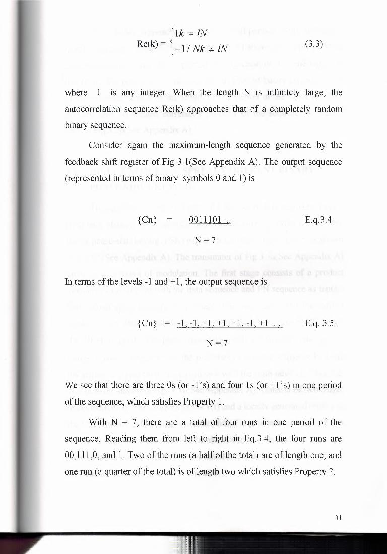
{Ik = IN
Rc(k) = -1 / Nk -:t:- IN (3.3)
where 1 is any integer. When the length N is infinitely large, the
autocorrelation sequence Rc(k) approaches that of a completely random
binary sequence.
Consider again the maximum-length sequence generated by the
feedback shift register of Fig 3. l(See Appendix A). The output sequence
(represented in terms of binary symbols O and 1) is
{Cn} = 0011101 ... E.q.3.4.
N=7
In terms of the levels -1 and + 1, the output sequence is
{ Cn} = -1 -1 + 1 + 1 + 1 -1 + 1. ..... E.q. 3.5.
N=7
We see that there are three Os ( or -1 's) and four 1 s ( or +l's) in one period
of the sequence, which satisfies Property 1.
With N = 7, there are a total of four runs in one period of the
sequence. Reading them from left to right in Eq.3.4, the four runs are '
00, 111, 0, and 1. Two of the nms (a half of the total) are of length one, and
one run (a quarter of the total) is of length two which satisfies Property 2.
31

Fig. 3.2a(See Appendix A) shows two full periods of the maximum
length sequence. Figure 3 .2b(See Appendix A) shows the corresponding
autocorrelation function Re( r) plotted as a function of the time lag r. In
this figure, the parameter Tc denotes the duration of binary symbol I or 0
in the sequence, and N is the length of one period of the sequence. The
periodic and two-valued correlation property of the sequence is clearly
seen in Fig.3.2b(See Appendix A).
3.4. DIRECT-SEQUENCE SPREAD COHERENT BINARY
PHASE-SHIFT KEYING
The spread-spectrum technique for the use of this technique over a
band-pass channel (e.g., satellite channel), we may incorporate coherent
binary phase-shift keying (PSK) into the transmitter and receiver, as shown
in Fig.3.5(See Appendix A). The transmitter of Fig.3.5a(See Appendix A)
involves two stages of modulation. The first stage consists of a product
modulator of multiplier with the data sequence and PN sequence as inputs.
The second stage consists of a binary PSK modulator. The transmitted
signal x(t) is thus a direct-sequence spread binary phase-shift-keyed
(DS/BPSK) signal. The phase modulation 8(t) of x(t) has one of two
values, 0 and n, depending of the polarities of the data sequence b(t) and
PN sequence c(t) at time tin accordance with the truth table of Table 3.2.
The receiver shown in Fig. 3.5b(See Appendix A), consists of two stages ' of demodulation. The received signal y(t) and a locally generated replica of
the PN sequence are applied to a multiplier. This multiplication represents
the first stage of demodulation in the receiver. The second stage of
demodulation consists of a coherent detector, the output of which provides
an estimate of the original data sequence.
32

Fig.3.4(See Appendix A). illustrates the waveforms for the first
stage of modulation. Part of the modulated waveform shown in
fig.3.4c(See Appendix A) is reproduced in fig.3.6a(See Appendix A), the
waveform shown here corresponds to one period of the PN sequence.
Fig.3.6b(See Appendix A) shows the waveform of a sinusoidal carrier, and
fig 3.6c(See Appendix A) shows the DS/BPSK waveform that results from
the second stage of modulation.
Table 3.2. Truth Table for Phase Modulation 8 (t), Radians
Polarity of Data Sequence b(t) at Time t
+ - Polarity of PN sequence + 0 7t
c(t) at time t - 7t 0
3.5. MODEL FOR ANALYSIS
In the normal form the transmitter, shown in Fig. 3.5a(See Appendix
A), the spectnun spreading is performed prior to phase modulation. For the
purpose of analysis, however, we find it more convenient to interchange
the other of these two operations, as in the model of Fig. 3.7(See
Appendix A). We are permitted to do this because the spectnun spreading
and the binary phase-shift keying are both linear operations. The model of
Fig.3.7(See Appendix A) also includes representations of the channel and
the receiver. In this model, it is assumed that the interference j(t) limits
performance, so that the effect of channel noise may be ignored.
Accordingly, the channel output is given by
33

y (t) = X (t) + j (t)
= C (t) S (t) + j (t)
where s(t) is the binary PSK signal, and c(t) is the PN sequence. In the
receiver, the received signal y(t) is first multiplied by the PN sequence c(t)
yielding an output that equals the coherent detector input u(t). Thus,
U (t) = C (t) y (t)
= C2 (t) S (t) + C (t) j (t)
= S (t) + C (t) j (t),
in the last line ofEq. 3.12, we have noted that, by design, the PN sequence
c(t) satisfies the property described in Eq. 3.9, reproduced here for
convemence:
for all t
Equation 3. 12 shows that the coherent detector input u( t) consist of a
binary PSK signal s(t) imbedded in additive code-modulated interference
denoted by c(t)j(t). The modulated nature of the latter component force the
interference signal (jammer) to spread is spectnun, such that the detection
of information bits at the receiver output is afforded increased reliability.
34

3.6. BIPHASE MODULATION
A phase-modulated carrier can be expressed in general as
s(t) = A sin [Wot+ 0(t)]
where A is the constant carrier amplitude and 0( t) represent the phase
modulation. In the case of biphase modulation, 0(t) will be either zero or
re. The values of 0(t) for various combinations of the binary message,
m(t), and the PN sequence, b(t) are shown in Table 3.3.
Table 3.3. Truth Table for 0(t)
m (t) 1 -1
b(t) 1 0 re -1 re 0
A block diagram of a system accomplishing biphase modulation is shown
in Fig.3.8(See Appendix A). This system employs a balanced modulator
that ideally produces the desired phase shift keying without any residual
carrier at the output. It is necessary that the message bit duration lm be an
integral multiple of the chip duration tl as shown in Fig.3.9(See Appendix
A).
35

3.7. QUADRIPHASE MODULATION
A block diagram of a system producing quadriphase modulation is
shown in Fig.3.lO(See Appendix A). In this case two balanced modulators
are used and the carriers to these two modulators are 90 degrees apart in
phase. There are also two modulo-2 adders that at the message binary
sequence to do so. This means that each chip of the PN code is stretched
to a duration of 2tl before being added to the binary message. The
quadriphase signal can again be represented as
s (t) = A sin [Wot+ 0(t)]
in which A is the carrier amplitude and 0(t) is the phase modulation. The
relation of 0(t) to the state of the message and the states of the PN code
sequence is shown in Table 3.4.
Table 3.4. Truth table for 0(t)
ill (t) bl(t) b2(t) 1 -1
1 1 rc/4 5rc/4 1 -1 7rc/4 3rc/4 -1 1 3rc/4 7rc/4 -1 -1 5rc/4 rc/4
It may be noted that the message modulation is still binary.
36

3.8. A NOTION OF SPREAD SPECTRUM
An important attribute of spread spectnun modulation is that it can
provide protection against externally generated interfering (jamming)
signals with finite power. The jamming signal may consist of a fairly
powerful broadband noise or multitone waveform. That is directed at the .:t!,Sr Af)f;4J ·-(J ~-&JZ
receiver for the purpose of disrupting conoo.tt'nication. Protection against
jamming waveforms is provided by purposely making the information
bearing signal occupy a bandwidth far the excess of the minimum
bandwidth necessary to transmit it. This has the effect of making the
transmitted signal assume a noise-like appearance so as to bland into the
background. The transmitted signal is thus enable to propagate through the
channel undetected by anyone who may b~~\:lli~;3 'f e !~~~~k~a,_ think of spread spectrum as a method of "camouiawg.'~he information-
bearing signal.
One method of widening the bandwidth of an information-bearing
( data) sequence involves the use of modulation. Specifically, a data
sequence b(t) is used to modulate a wide-band pseudo-noise (PN)
sequence c( t) by applying these two sequences to a product modulator or
multiplier, as in Fig.3.3a(See Appendix A). For this operation to work both
sequences are represented in there polar forms that is, in terms of two
levels equal in amplitude and opposite polarity (e.g., -1 and+ 1). We know
from fourier transform theory that multiplication of two unrelated signals
produces as a signal whose spectrum equals the convolution of a spectnun
of the two component signal. Thus, if the data sequence b( t) is narrowband
and the PN sequence c(t) is wideband the product signal m(t) will have
spectnnn that is nearly the saine as the PN sequence. In other words, in the
37

context of our present application, the PN sequence performs the role of a
spreading code.
By multiplying the information-bearing signal b(t) by the spreading
code c(t) each information bit is "chopped" up into a number of small time
increments as illustrated in the waveforms of Fig.3.4(See Appendix A).
The small time increment are commonly referred to as chips.
For baseband transmission, the product signal m(t) represents the
transmitted signal. We may thus express the transmitted signal as
m(t) = c(t) b(t)
the received signal r(t) consist of the transmitted signal m(t) plus and
additive interference denoted by i( t) as shown in the channel model of
Fig.3.3.b(See Appendix A). Hence
r(t) = m(t) + i(t)
= c(t) b(t) + i(t)
to recover the original data sequence b(t) the received signal r(t) is applied
to a demodulator that consist of a multiplier followed by a low-pass filter
as in Fig.3.3c(See Appendix A) the multiplier is supplied with a locally
generated PN sequence that is an exact replica of that used in the
transmitter. Moreover, we assume that the receive operates in perfect
synchronism with the transmitter which means that the PN sequence in the
receiver is lined up exactly with that in the transmitter. The resulting
demodulated signal is therefore given by
38

z(t) = c(t) r(t)
= c2(t) b(t) + c(t) i(t)
equation 3.8 shows that the desired signal b(t) is multiplied twice by the
spreading code c(t) where as the unwanted signal i(t) is multiplied only
once. The spreading code c(t) alternates between the levels -1 and + 1, and
the alternation is destroyed when is squared: Hence
for all t
accordingly, we may simplify Eq. 3.8.as
z(t) = b(t) + c(t) i(t)
we thus see form e. q., 3 .10. that the data sequence b( t) is reproduce at the
multiplier output in the receiver except for the effect of the interference
represented by the additive term c(t) i(t). Multiplication of the interference
i(t) by the locally generated PN sequence c(t) means that the spreading
code will affect the interference just as it did the original signal at the
transmitted. We now observe that the data component b(t) is narrowband,
whereas the spurious component c(t) i(t) is wideband. Hence, by applying
the multiplier output to a baseband (low-pass) filter with a bandwidth just
large enough to accommodate the recovery of the data signal b( t) the
spurious component c(t) i(t) is made narrowband, thereby removing most
39

of its power. The effect of the interference i(t) is thus significantly reduce
at the receiver output.
In summary, the use of spreading code (with pseudo-random
properties) in the transmitter produces a wideband transmitted signal that
appears noise-like to a receiver that has no knowledge of a spreading code
we note that ( for a prescribed data rate) the longer we made the period of
the spreading code, the closer will the transmitted signal be to a truly
random binary wave, and the harder it is to detect.
40

CHAPTER4
4.1. FREQUENCY-HOP SPREAD SPECTRUM
In the type of spread spectrum systems discussed previously, the use
of a PN sequence to modulate a phase-shift-keyed signal achieves
instantaneous spreading of the transmission bandwidth. The ability of such
a system to combat the effects of jammers is determined by the processing
gain can be which is a function of the PN sequence length. The processing
gain can be made larger by employing a PN sequence with narrow chip
duration, which, in, turn, permits a great transmission bandwidth and more
chips per bit. However the capabilities of physical devices used to
generate the PN spread-spectrum signals impose a practical limit on the
attainable processing gain. Indeed, it may turn out that the processing gain
so attained is still not large enough to overcome the effects of some
jammers of concern, in which case we have to resort to other methods.
One such alternative method is to force the jammer to cover a wider
spectrum by randomly hopping the data-modulated carrier for one
frequency to the next. In effect the spectrum of the transmitted signal is
spread sequentially rather that instantaneously; the term " sequentially"
refers to the pseudo-random-ordered sequence of frequency hops.
The type of spread spectrum in which the carrier hops randomly
from one frequency to another is called frequency-hop (FH) spread
spectrum. A common modulation format for FH systems is that of M-ary
frequency-shift keying (MFSK). The combination is referred to simply as
FH/MFSK.
41

Two basic (technology-independent) characterizations of frequency
hopping are:
1. Slow-frequency hopping, in which the symbol rate Rs of the MFSK
signal is and integer multiple of the hop rate Rh. That is several symbols
are transmitted on each frequency hop.
2. Fast-frequency hopping, in which the hop rate Rh is an integer multiple
of the MFSK symbol rate Rs. That is, the carrier frequency will change to
hope several times during the transmission of one symbol.
4.2. SLOW - FREQUENCY HOPPING
TRANSMITTER
Figure 4. la(See Appendix A) shows the block diagram of an
FH/MFSK transmitter, which involves frequency modulation followed by
mixing. First the incoming binary data are applied to an M-ary FSK
modulator. The resulting modulated wave and the output from a digital
frequency synthesizer are then applied to a mixer that consists of a
multiplier followed by a filter. The filter is designed to select the sum
frequency component resulting from the multiplication process the
transmitted signal. In particular, successive (not necessarily disjoint) k-bit
segments of a PN sequence drive the frequency synthesizer, which enables
the carrier frequency hop over 2k distinct values. One a single hop the
bandwidth of the transmitted signal is the same as that resulting from the
use of a conventional M-ary frequency-shift-keying (MFSK) format with
an alphabet of M = 2k orthogonal signals. However, for a complete range
of 2k-frequency hops, the transmitted FH/MFSK signal occupies a much
larger bandwidth. Indeed , with present-day technology, FH bandwidth of
the order of several GHz are attainable which is an order of magnitude
42

larger than that achievable with direct-sequence spread spectra. An
implication of these large FH bandwidths is that coherent detection is
possible only within each hop, because frequency synthesizers are unable
to maintain phase coherence over successive hops. Accordingly, most
frequency-hop spread- spectrum communication systems use noncoherent
M-ary modulation schemes.
4.3. RECEIVER
In the receiver depicted in Fig.4.1 b(See Appendix A), the frequency
hopping is first removed by mixing ( down-converting) the received signal
with the output of a local frequency synthesizer that is synchronously
controlled in the same manner as that in the transmitter. The resulting
output is then band-pass filtered, and subsequently processed by a
noncoherent M-ary FSK detector. To implement this M-ary detector, we
may use a bank of M noncoherent matched filters, each of which is
matched to one of the JvIFSK tones. An estimate of the original symbol
transmitted is obtained by selecting the largest filter output.
An individual FH/MFSK tone the shortest duration is referred to as
a chip;
The chip rate, Re, for an FH/MFSK is defined by
Re = max (Rh,Rs)
where Rh is the hope rate, and Rs is the symbol rate.
A slow FH/MFSK signal is characterized by having multiple
symbols transmitted per hop. Hence , each symbol a slow FH/MFSK
signal is a chip. Correspondingly, in a slow FH/MFSK system the bit rate
43

Rb of the incoming binary data, the symbol rate Rs of the MFSK symbol
the chip rate Re, and the hop rate Rh are related by
Re = Rs = Rb I K :2: Rh
where K = logz U.
Figure 4.2a(See Appendix A) illustrates the variation of the frequency of a
slow FH/MFSK signal with time for one complete period of the PN
sequence. The period of the Pn sequence is (22)2 - 1 = 15. The FH/MFSK
has following parameters:
Number of bits per MFSK symbol
Number of MFSK tones
Length of PN segment per hop
Total number of frequency hops
K=2
M=2k=4
k=3
2k= 8
In this example, the carrier is hopped to a frequency after transmitting two
symbols or equivalently, four information bits. Fig.4.2a(See Appendix A)
also includes the input binary data, and the PN sequence controlling the
selection of FH carrier frequency. It is noteworthy that although there are
eight district frequencies available for hopping, only three of them are
utilized by the Pn sequence.
Figure 4.2b(See Appendix A) shows the variation of the developed
frequency with time. This variation is recognized to be the same as that of
a conventional MFSK signal produced by the given input data.
At each hop, the MFSK tones are separated in frequency by an
integer multiple of the chip rate Re = Rs, ensuring their orthogonality. The
44

implication of this condition is that any transmitted symbol will not
produce any crosstalk in the other M - 1 noncoherent matched filters
constituting the MFSK detector of the receiver in Fig.4.1 b(See Appendix
A); By " crosstalk" we mean the spillover from one filter output into and
adjacent one. The resulting performance of the slow FH/MFSK system is
the same as that for the noncoherent detection of conventional (unhopped)
MFSK signals in additive white Gaussian noise (A WGN). Thus the
interfering (jamming) signal has an effect on the FH/MFSK receiver, in
terms of average probability of symbol error, equivalent to that of additive
white Gaussian noise on a conventional noncoherent M-ary FSK receiver
experiencing no interference.
Assuming that the jammer decides to spread its average power J
over the entire frequency-hopped spectrum, the jammer' s effect is
equivalent to an A WGN with power spectral density No/2, where
No= J /We and We is the FH bandwidth. The spread-spectnun system is
thus characterised by the symbol energy-to-noise density ratio:
E/No = (P/J) I (We I Rs)
where the ratio P/J is the reciprocal of the jamming margin. The other ratio
is the processing gain of the slow FH/MFSK system defined by
PG =We /Rs
=2k
That is, the processing gain ( expressed in decibels) is equal to
45

IO logiozk = 3k, where k is the length of the PN segment employed to
select a frequency hop.
This result assumes that the jammer spreads its power over the entire FH
spectrum. However, if the jammer decides to concentrate on just a few of
the hopped frequencies, then the processing gain realized by the receiver
would be less than 3k decibels.
4.4. FAST FREQUENCY HOPPING
A fast FH!MFSK system differs from a slow FH!MFSK system in
that there are multiple hops per M-ary symbol. Hence, in a fast FH!MFSK
system, each hop is a chip. In general fast-frequency hopping is used to
defeat a smart jammer' s tactic that involves two functions: measurement of
the spectral content of the transmitted signal, and retuning of the
interfering signal to that portion of the frequency band. Clearly, to
overcome the jammer, the transmitted signal must be hopped to a new
carrier frequency before the jammer is able to complete the processing of
these two functions.
Figure.4.3a(See Appendix A) illustrates the variation of the
transmitted frequency of a fast FH!MFSK signal with time. The signal has
the following parameters:
Number of bits per MFSK symbol
Number of MFSK tones
Length of PN segment per hop
Total number of frequency hops
K=2
M=2k=4
k=3
2k= 8
In this example, each MFSK symbol has the same number of bits and
chips; that is the chip rate Re is the same as the bit rate Rb. After each
46

chip, the carrier frequency of the transmitted MFSK signal is hopped two
different value, except for few occasions when the k-chip segment of the
PN sequence repeats itself.
Figure 4.3b(See Appendix A) depicts the time variation of the
frequency of the dehopped MFSK signal.
For data recovery at the receiver, noncoherent detection is used.
However the detection procedure is quite different from that used in a slow
FH/MFSK receiver. In particular, two procedures may be considered:
1. For each FH/MFSK separate decisions are made on the K frequency
hop chips received, and a simple rule based on majority vote is used to
make an estimate of the dehopped MFSK symbol.
2. For each FH/MFSK symbol, likelihood functions are computed as
fimctions of the total signal received over chips, and the larger one is
selected.
A receiver based on the second procedure is optimum in the sense
that it minimizes the average probability of symbol error for a given
Eb/No.
47

CHAPTERS
5.1. TIME HOPPING
A time-hopping waveform is illustrated in Fig 5. l(See Appendix A).
The time axis is divided into intervals known as a frames, and each frame
is subdivided into M time slots. During each frame one and only one time
slot will be modulated with a message by any reasonable modulation
method. The particular time slot that is chosen for a given frame is selected
means of a PN code generator. All of the message bits accumulated in the
previous frame are transmitted in a burst during the selected time slot. To
quantify this concept, let
T f = frame duration
K = number of message bits in one frame
Tf = ktm
The width of each time slot in frame is T f 1M and the width of each
bit in the time slot is T f lkM, which is simply tm/M. This indicates that the
transmitted signal bandwidth is 2M times the message bandwidth, and
hence the processing gain of a time-hopping system is simply twice the
number of time slots in each frame when biphase modulation is used, and
half this when quadriphase modulation is used.
A typical time-hopping receiver is shown in Fig. 5.2(See Appendix
A). It consists of an on-off switch that is driven by a PN code generator in
order to do the switching at the proper time in each frame. The output of
this switch is then demodulated by either a two-phase or four-phase
demodulator, depending on the nature of the transmitted signal. Bit
48

synchronization is also required and the output of the bit synchronizer is
used to control the clock that drives the PN code generator to maintain
synchronization. Since the message bits are coming out a much greater rate
than that at which the were originally produced, each burst must be stored
and then retimed to the normal message rate. Time hopping is most often
used in conjunction with other spread-spectrum techniques.
Interference among simultaneous users in a time-hopping system
can be minimized by coordinating the times at which each user can
transmit a signal. This also avoids the near-far problem. In a
noncoordinated system, overlapping transmission bursts will result m
message errors , and this will normally require the use of error- correction
coding to restore the proper message bits. The acquisition time is similar to
that of direct-sequence system for a given bandwidth. Implementation is
simpler than that of a frequency-hop system.
5.2. THE TIME-HOPPED SIGNAL
A typical time-hopped signal is represented in Fig. 5.3(See
Appendix A). The duration of each frame is Tf seconds and each frame
there is one transmission burst that will contain k message bits. If there are
M such burst periods in each frame, then the width of each burst is T f 1M
and the frame duration must be
Tf = ktm
Since these are transmitted in T f 1M seconds, the duration of each chip
within a burst must be
49

tl = Tf I kM
=2Tf lkM
biphase modulation
quadriphase modulation
Note that this result depends upon whether bi phase modulation or
quadriphase modulation is used.
Sine the bandwidth of the transmitted signal is equal to
Bs = 2 I ti
this becomes, Bs = 2kM I Tf
= kM I Tf
bi phase
quadriphase
Again this depends upon whether biphase or quadriphase modulation is
used.
The processing gain of the time-hopped signal is the ratio of the signal
band-width to the message bandwidth and becomes
PG = Bs I Bm = (2kM I T f) I (1 I tm) = 2M
= (kM I Tf) I (1 I tm) = M
bi phase
quadriphase
For a given processing gain, the interference rejection and the
jamming margin are not be same for direct-sequence systems. Also the
evaluation of intercept energy may be quite different, because the energy is
concentrated in such a small time interval. Because of this small time
interval, the transmitted power is large during this time and hence signals
may be detected on a single-hop basis that could not be detected if they
used the same energy as a direct-sequence system.
50

5.3. CHIRP SPREAD SPECTRUM
A chirp spread- spectnun system utilized linear frequency
modulation of the carrier to spread the bandwidth. This is a technique that
is very common in radar systems, but is also used in communication
systems. The relationships between frequency and time are shown in Fig
5 .4(See Appendix A), in which T is the duration of a given signal
waveform and B bandwidth over which the frequency is varied. In this
case the processing gain is simply BT. It is also possible to use nonlinear
frequency modulation, and in some cases this may be desirable.
5.4. COMPARISON OF MODULATION METHODS
It is desirable at this point to include a list of the advantages and
disadvantages of the three types of spread-spectnun systems that have
been discussed so far. The purpose of this comparison is to illustrate that
each method has its advantages and disadvantages, and that it may be
possible to overcome some of these this advantages by the use of a
combination of techniques. The advantages and disadvantages of the
various systems are outlined below.
5.5. DIRECT-SEQUENCE (PN) SYSTEMS
Advantages
* Best noise and antijam performance.
* Most difficult to detect.
* Best discrimination against multipath.
51

Disadvantages
* Requires wide-band channel with little phase distortion.
* Long acquisition time.
* Fast code generator needed.
* Near-far problem.
5.6. FREQUENCY-HOPPING (FH) SYSTEMS
Advantages
* Greatest amount of spreading.
* Can be programmed to avoid portions of the spectrum.
* Relatively short acquisition time.
* Less affected by near-far problem.
Disadvantages
* Complex frequency synthesizer.
* Not useful for range and range-rate measurement.
* Error correction required.
5. 7. TIME-HOPPING (TH) SYSTEMS
Advantages
* High bandwidth efficiency.
* Implementation simpler than FH.
52

,., . .-_,~ I;~.., ,. " i' .':;· t.l' i. i' '\i', .~"', \ I f,_j ••.•• ,. t
f·_ • ..,.. 1 •,·, r~y -< \ - . . ,-.. * Useful when transmitter is average power limited but notl;peak
'~·"·, -~
\./.;;"' - .ioC:J., ""-~-- lEf P , ..... ..___ .. power limited.
* Near-far problem avoided in a coordinated system.
Disadvantages
* Long acquisition time.
* Error correction needed.
5.8. HYBRID SPREAD-SPECTRUM SYSTEMS
The use of the hybrid system attempts to capitalize upon the
advantage of a particular method while avoiding the disadvantages. Many
different hybrid combinations are possible. Some of these are
PN/FH
PN/TH
FH/TH
PN/FH/TH
To illustrate how a hybrid system might operate, consider of the
case of a PN /FH hybrid system. This system might use a PN code spread
the signal to an extent limited by either code generator speed or acquisition
time. When frequency hopping would be used to increase the frequency
spread. The difference between the frequencies in the frequency-hopping
portion of the system would normally be equal to the bandwidth of the PN
code modulation. Usually some from of noncoherent message modulation
is used because of the frequency hopping, and differential phase shift
keying is a typical example. Since there are fewer frequencies to be
implemented, the frequency synthesizer is similar for a given overall band-
53

width. Thus this system gains some of the advantages of direct sequence
systems and of frequency-hop systems, and avoids some of the
disadvantages of both. A typical example of a PN !FH system is shown in
the following.
5.9. EXAMPLE OF PN/FH SYSTEM
* PN rate of 250,000 chips per second.
* FH spreading to 2.048 Ghz (8192 frequencies separated by 250 KHz).
* Error correction from the third rate convolutional coding.
* Message rate: 7 5 b/s or 2400 b/s.
*PG= 74.3 dB at 75b/s = 59.2 dB at 2400 b/s.
54

CHAPTER6
6.1. APPLICATION OF SPREAD SPECTRUM
TO COMMUNICATIONS
There are many possible applications and only a few are presented
here. One of the most important applications is usually referred to as
multiple access arises when a number of independent users are required to
convey their messages through a common facility. An outstanding example
of this is the satellite communication system in which all messages from
ground stations mast pass through a common satellite repeater. Another
such application is ground-based mobile communications in which mobile
vehicles must communicate with a central base station.
The classical method of providing multiple-access capability is
frequency division(FDMA). In frequency division each user is assigned a
particular frequency channels are occupied the system has reached its
capacity and a further users may be accommodate.
A more recent technique for providing multiple access is time
division multiple access (TDMA). In time-division multiple access, each
user is assigned particular time slot within a time frame, and during this
time slot, transmits a portion of a message by any standard digital
technique. Time division multiple access is an important application for
satellite communications as well as ground-based digital communication
systems. Again, however, when all time slots are occupied the system is
operating at capacity and no additional users can be accommodate.
55

This third general class of multiple-access communication systems
is usually referred to as code-division multiple access (CDMA). Code
division multiple access is always accomplished by means of spread
spectrum. In this system each user is assigned a particular code, that is ,
either a particular PN sequence or a particular frequency-hopping pattern.
It is the fact that each user has a unique code that enable the messages to
be separated at the receiving point.
An additional advantage of CDMA is that the messages intended for
one user are not readily decodable by other users, because they may not
know the proper codes or have the equipment for the generating the
appropriate 'reference signals. Thus there is a privacy feature that is not
available in other multiple access techniques. An important consideration
in CDMA is the number of users that can be accommodated
simultaneously.
A second application of spread spectrum is usually referred to as
selective calling. In a sense selective calling is the inverse of multiple
access, that is, there is a central station that must communicate with a
number of different receiving points and it wishes to do so on a selective
basis. The message is intended for one receiving point and should not be
received points. This is accomplished by having distinct codes assigned to
each receiving point. An example of such a system might be ground-based
radio system in which there is a central station that this communicating
with a number of mobile receivers.
Another application of spread spectrmn arises from its ability to
resist the effects of intemational jamming. This antijam capability was in
fact the primary reason for early consideration of spread spectrum
communications by the military.
56

An application of spread spectrum that is also of interests to the
military is that of covert communication or low probability of intercept. In
this case it is desired to maintain in signal spectral density that is
sufficiently small that its presence is not readily detected or that it cannot
be detected on a chip-by-chip basis.
A characteristic of spread spectrum that is particular interest in
mobile communications is the ability of a wide-band signal to resist the
effect of multipath fading. A property of multipath fading is that
frequencies separated by only a few hundred KHz. may fade essentially
independently. Thus at any given time when the signal has a large
bandwidth, only a small potion of the bandwidth will be in a fade. The
average received signal power thus can be made more nearly constant than
it would be for a narrow-band signal. This resistance to fading is a
important-consideration in the potential application of spread spectnun to
mobile communication situations.
A sixth reason for using spread spectnun lies in it is ability to
accommodate a secure communication system. If code are made
sufficiently complex, it becomes very difficult to break them, and for
unauthorised listeners to determined what the message actually is. This
secrecy capability is important not only to the military, but 111 many
commercial applications.
A fmal application of spread spectnun lies in it is ability to yield
accurate distance information. It is well known that a broadband signal can
be result in time much more precisely than a narrow-band signal. Thus by
transmitting a signal with a large bandwidth, it is possible to measure delay
times much more accurately and obtain more accurate range information.
This is of importance rub only in radar system, but also in navigation
system. Thus there are many spread spectnun radars that are intended for

high-resolution target detection, and there are several electronic navigation
system in coorporating spread spectrum signals.
6.2. EXAMPLES OF SPREAD - SPECTRUM SYSTEMS
The purpose of this section is provide a very brief description of
certain spread-spectnun systems that are either in operation or in the
planning phase at the present time.
One example of the direct-sequence system is the satellite
navigation system known as the Global Positioning System (GPS). This
system employs spread spectrum for the purposes: One purpose is to
accommodate the multiple-access capability, since each user of the system
must receive signals from four different satellites in order to make proper
measurements of the user's position. These signals arriving constantly, so
it is necessary that the user be able to distinguish among them. Therefore,
distinct codes are assigned to the various satellites so that users can tell
which signals they are receiving. The second reason is to increase the
resolution capability so that the accuracy of the system is improved. For
this purpose there is a PN sequence running at a chip rate of 10.23
megachips per second and modulated with data at a rate of 50 bis. This leads to a processing gain of about 56 dB an enables the system to operate
with input signal-to-noise rations of the order of -34 dB.
Another direct-sequence system is the Telecommunication Data
Relay Satellite System (TDRSS), which relays data to and from the space
shuttle. In this case spread spectrum is used primarily to reduce the energy
density of the radiation at the surface of the earth in order to meet CCIR
requirements. The S-band portion of the system utilizes a PN code running
at 11.232 megachips per second with a code period of 204 7 chips. This is
58

modulated by data either at 32kb/s. or 2 l 6kb/s. Thus the processing gain is
not extremely high, but this was not the original objective of using spread
spectrum.
An example of a frequency-hopping system that is being developed
is SINCGRAS. This system operates in the 30-to 88- MHz band and
utilizes a very long hopping sequence with hop frequencies separated by
25 kHz. The hop rate is quite low and each hop is modulated with binary
FM. Special features are incorporated to make it possible to reduce the
acquisition time to a small enough value that push-to-talk operation is
possible.
6.3. CODE-DIVISION MULTIPLE ACCESS
Code-division multiple Access is explained here as an example of
application of SS-System. The two most common multiple access
techniques for satellite communication are frequency-division multiple
access (FDMA) and time-division multiple access (TDMA). In FDMA, all
users access the satellite channel by transmitting simultaneously but using
this joint frequency bands. In TDMA, all users occupy the same RF
bandwidth of the satellite channel by the transmit sequentially in time.
When, however, all users are permitted to transmit simultaneously and also
occupy the same RF bandwidth of the satellite channel, then some other
method must be provided for separating the individual signals at the
receiver. Code division multiple access (CDMA) is the method that makes
it possible to perform this separation.
To accomplish CDMA, spread spectrum is always used. In
particular, each user is assigned a code of its own, which performs the
59

direct-sequence or frequency-hop spread-spectrum modulation. The design
of the codes has to cater for two provisions:
1. Each codes approximately orthogonal (i.e., has low cross-correlation)
with all the other codes.
2. The CDMA system operates asynchronously, which means that the
transition times of a user's data symbols do not have to coincide with
those of the other users.
The second requirement complicates the design of good codes for
CDMA. The use of CDMA offers three attractive features over TDMA.
1. CDMA does not require an external synchronization network, which is
an essential feature of TDMA.
2. CDMA offers gradual degradation in performance as the number of
users increased. It is therefore relatively easy to add new users to the
system.
3. CDMA offers an external interference rejection capability (e.g.,
multipath rejection or resistance to deliberate jamming).
6.4. SUMMARY AND DISCUSSION
Direct-sequence M-ary phase shift keying (DS/MPSK) and
frequency-hop M-ary frequency shift keying (FH/MPSK) represent to
principle categories of spread spectrum communication. Both of them rely
on the use of a pseudo-noise (PN) sequence, which is applied differently in
the two categories.
In a DS/MPSK system, the PN sequence makes the transmitted
signal assume a noise-like appearance by spreading its spectrum over a
60

board range of frequencies simultaneously. For the phase-shift keying, we
may use binary PSK (i.e., M = 2) with a single carrier. Alternatively, we
may use QPSK (i.e.,M = 4),in which case the data are transmitted using a
pair of carriers in phase quadrature. In spread spectrum system, bandwidth
efficiency is usually note of prime concern.
In an FH/MFSK system, the PN sequence makes the carrier hop
over a number of frequencies in a pseudo-random manner, with the
measure that the spectrum of the transmitted signal is spread in a
sequential manner.
Naturally, the direct-sequence and frequency-hop spectrum
spreading techniques may be employed in a single system. The resolution
system is the referred to as a hybrid DS/FH spread-spectrum system. The
reason for seeking a hybrid approach is that advantage of both the directs
sequence and frequency-hop spectrum-spreading techniques are realized in
the same system. Indeed the hybrid approach is the only practical way of
realising extremely wide-spectrum spreading.
For its proper operation, spread-spectrum communication requires
that the locally generated PN sequence use in the receiver to despread the
received signal be synchronized to the PN sequence use to the transmitted
signal in the transmitter. A solution to the synchronized problem consists
of two parts: acquisition and tracking. In acquisition or coarse
synchronization, the two PN codes are aligned to within a fraction of a
chip in as short a time as possible. Once the incoming PN code has been
acquired, tracking, or fine synchronization, takes place. Typically, PN
acquisition proceeds in two steps. First, the received signal is multiplied by
a locally generated PN code produce a measure of correlation between it
and the PN code used in the transmitter. Next, an appropriate decision-rule
and search strategy is used to process the measures of correlation so
61
obtains to determine whether the two codes are in synchronism and what
to do if they are not. As for tracking, it is accomplished using phase-lock
techniques very similar to those used for the local generation of coherent
carrier references. The principle difference between them lies in the way in
which phase discrimination is implemented.
A discussion of spread-spectrum communications would be
incomplete without some reference to jammer waveforms, The jammers
encountered in practice include the following types.
1. The barrage jammer, which consists of band-limited white
Gaussian noise of high average power. The barrage noise j ammer is a
brute-force jammer that does not exploit any knowledge of the antijam
communication system except for its spread bandwidth.
2. The partial-band noise jammer, which consists of noise whose
total power is evenly spread over some frequency band that is a subset of
the total spread bandwidth. Owing to the smaller bandwidth, the partial
band noise jammer is easier to generate than the barrage noise jummer.
3. The pulsed noise jammer which involves transmitting wideband
noise of power
Jpeak = J/p
for a fraction p of the time, and nothing for the remaining fraction 1-p of
the time. The average noise power equals J.
4. The single-tone jammer, which consists of a sinusoidal wave
whose frequency lies inside the spread bandwidth. A such, it is the easiest
of all jamming signals to generate.
62

5. The multitone jamrner, which is the tone equivalent of the partial
band noise jammer.
The pulsed-noised jamrner is particularly effective against DS/BPSK
systems. Correspondingly partial-band noise and multitone jammers a most
effective against FH/MFSK system. Those jamming strategies are effective
because they are able to concentrate jamming resources on some fraction
of the transmitted symbols, thereby resulting bursts of errors at the receiver
output. To deal with this problem, a spread-spectnun system will rely on
very powerful error-correcting codes combined with interleaving.
Specifically in the transmitter, the incoming data are first encoded,
interleaved, and than applied to a spread-spectnun modulator. In the
receiver, the received signal is despread, demodulated, deinterleaved, and
then detected. Indeed, than error correcting codes and interleaving are
combined with hybrid DS/FH spread spectnun (i.e., pseudo-random
chipping and pseudo-random frequency hopping), the result is a digital
communication system that can provide very significant projection against
external noise, unintentional interference, and intentional jamming.
63

REALIZATION
OF
PROJECT

J// lJ / I tiL I U I VL l I UI V CJCI V C r\111-Ll
I • ,-,: 7c, ~ ~ ,~- ~ "!" %, F [(;J .Ji.\ ~ ·- 'k J \0 - h,.. ct . -z~ 11,,t
~ Q r- " ~- -i.. ~ rs r'1 .fl lt9 N'l "- I r V,
<:i I '
~ 4~ " '7- o-/- ~
' re ~ C> '
~ cn,J\~ I. I ;:. <'l "" ~ 1. i;n 'Z(!J cl
~ I
" I)_. Cl oz. ' ._r, ·.JI 119 ~ "I - l lA
I - ~
<::i if ~~ ~} I ~ ~ '- ~ -z:
f"IJ) -c' C l<t' ,<' <'l .J)~ Q;)~ J' -- {. ' <S" _1 't/s) ~
~ ~ ~ ~ .':i '° L <:("
J\. I .J) . L- t .- l'-. <.!) " I~ ~
I'-, \ e- I ~
vj ~ i:::i Q
•... _ _J ~ s;\-
' ,.._
~ a-/~
~~
•..•. tt\ ?-.
C, L---
'° z
~ C ~ U) t(\ - f(SJ ~~ l"-- -.!'~ '-- 01 ~
I .ls- ~ <!r ~
I ~ ~ ~ '-,() "' ~ ~ lY) ..n "J', - ~ {/J -
<)I ~ <'<) I I
"ls _p, I
Q ~ Y, • I I
~ __::_ '7.-0 ' ~ ~r J : I ~ -z: i- I i ~ ~ 0 J- <I)
~ ~ .•.. (:ff l<S ' _).
"' ~ ~· ~ '° "::i. ~- I"- -Z(!J ,- ~ ~ I ~ Q ._r, <zj
I '& " " - ,() I
~ f'-- "l _,. v1 c\[
I;) - ('\ L -l - ~~ '7-
s;t- ~ ' -t: 0 U1 < 0
£"- ~ 'E,~ < J")> . -
2'.1 <./'I vj
~ > "'.) d 't?J .!s: ~ <O' 'O ~-:2-- Q:) ~ --~ "' JI <) ,j\
I~ ~ N-.. ~ ' ~
~~~ )- ~ '1- ~1 ~r ,< 0 ' i~ <.p .fl> i
{- ). '° ~ c'4 4
't~ + <t ~ ~ ~ i ~ G ~ C5 lei - ~ r- Q) <t
I !Y I.\\
~ '° ~ f--- - .. "') " Ln " ~ _l -~ L ~ 1.-i ~
·~ ~ (,j <:t- -...;.1,-~ -
o..,n r- Q ~l9 ,C .... ") z •. "'> ,._ ~
'7,& ~ is:<' c-1 v- "' ~
(/)
[11,~ 'VJ' - .•... ~ ' c<)
<l ~ ~ ~- ~ ~
.••.... Jl:l,\,.
I I
(!)
a
0 --1 u

YJULE?LIT 0£FL1EFIJJBS I I I I
I I I
I I
I I I I
I
I I
I--- I : I I I I I
'-- I I I i
i I [
~ ,._..
I \
\ I I
I
~ - I I I I j I I
I
~ I : '
I I j
I
i
[ - I .___
I I ! i I I
r I
I I I ' i
I I
I I I
I '---
I I
I 1 I
I I
I '----' ,___ I
I l l
\ I I I
I I
' I '--- I I
I I I I I I l
I I I
' !
I I
i
I I
- '---- '--- I
I
I I
I i
! I I I
'--
I : I I I ' ' '
I
I j
-
~ \) ~ \~ ~
I cl ~ l(::f "" 1'8 ~ ~ 'V\
0 ~ ~ 1& t~ ~ --I I~ ,.j "1 I~ lg <".I
l 'I "i ~ 0 ~ I Ii I~
1<8 - I<& l(S ' ~ <& I -
(:j
- ~d/o ao z -1az z3 s do 1~- c1n_:1 _ ..:1 a _ SNQL.Lt(/J/Jg_Wf1J I. N3 Y 3 ..:I _f LO

t Q
I
: I

~National ~ Semiconductor MM54HC30/MM74HC30 a-tnput NANO Gate
I General Description This NANO gate utilires acvarcec ~:s C~AOS tech nology to achieve ope,-aor..g ~ ~ ::.o LS. TTL gates with the !ow power consump.JOn Of stan.C:cid CYOS inte- ,;rated circuits. This device has h19h noese WiVIU"!!ty and the
I ,o,llty to drive 1 O LS- TTI. toads. The 54HC/7 4-iC 'og>c fami ly is functionally as well as pin-out compauble wn.-ii the stan
j dard 54LS/74LS logic family. All inputs are protected from ,1 damage due to static discharge by internal diode damps to Vee and ground.
Features • Typical prnpagana, oeay: 20 ns • Wide power suwt, range: 2-SV • Lew quiescent currant: 20 uA maximum (7 4.HC Senss) • Low input current l µA mamnum • Fanoot of 10 LS-TTI. loads
j Connection and Logic Diagrams
'V I I L- I ! 1
Oual•ln-Une Packago Yee NC H a NC MC
,. 1 ,, I 12 j,, I ,o .•. .,,,.._--
, , Top..-
Order Number MM54ttC30" or MM74HC-.>O· 'Ptease k::ok mto Section 3, Appendix O h?f" a .•. ;1J!ab4ityof Yanot.:~ p~ rypes.
Y-ABCDEFQH
TliF!SrN-1
-.,..

1 ~ National . \~Semiconductor MM54HCOO/MM74HCOO Quad 2-lnput NANO Gate General Description These NANO gates utilize advanced silicon-gate CMOS technology to achieve operating speeds similar to LS- TTL gates with the low power consumption of standard CMOS integrated circuits. All gates have buffered outputs. All de vices have high noise immunity and the ability to drive 10 LS-TTL loads. The 54HC/74HC logic family is functionally as well as pin-out compatible with the standard 54LS/74LS logic family. All inputs are protected from damage due to static discharge by internal diode clamps to Vee and ground.
Features • Typical propagation delay: 8 ns • Wide power supply range: 2-6V • Low quiescent current: 20 µA maximum (7rtHC Series) a Low input current: 1 µA maxrmum • Fanout of 10 LS-TTL loads
Connection and Logic Diagrams
Dual-In-Line Package
vce 14
83 AJ Y3
Y1 A2 TUF/52'?2-1 Al 81 Top View
Order Number MM54HCOO' or MM74HCOO' 'Please look into Secucn 8. Aooenoix D tor avauabrhtv or various packaqe types.
: y TL, F S292-2
I I Li~~~~-'----~~~~~~~~~~~~~

j
MM54HC11/MM74HC11 Triple 3-lnput AND Gate
/.
~National ~ Semiconductor
General Description These AND gates utilize advanced silicon-gate CMOS tech nology to achieve operating speeds similar to LS-TTL gates with Iha low power consumption of standard CMOS inte graled circuits. All gates have buffered outputs, pro~ing nigh noise immunity and the ability to drive 10 LS- TTL loads. The 54HC/74HC logic family is !unctionaliy as wsuas pin out compatible with the standard 54LSl74LS logic family. All inputs are protected from damage due to static dis charge by internal diode clamps to Vee and ground.
Features • Typical propagation delay: 12 ns • Wide power supply range: 2-6V • Low quiescent current 20 ,,A maximum (7 4HC Series) • Low input current l JJ-A maximum ..__ ----.. • Fanout of 10 LS-TIL roads
Connection and Logic Diagrams
Dual-ln-liPa Package
TLJF/~298-1
Top View
Order Number MM54HC11• or MM74HC11• 'Please look into Section 8. AppendlJ.: 0 to- ava1iat!lliry ot venous pecxaqe types.
11.JFl'SZ<JB-2
(1 OF 3 GATES)

MM54HC08/MM74HC08 Quad 2-lnput AND Gate
~National ~ Semiconductor
General Description These AND gates utilize advanced silicon-gate CMOS tech nology to achieve operating speeds similar to LS- TIL gates with the low power consumption of standard CMOS inte grated circuits. The HCOB has buffered outputs. providing high noise immunity and the ability to drive to LS- TIL loads. The 54HC/7 4HC logic family is functionally as well as pin out compatible with the standard 54LS174LS logic family. All inputs are protected from damage due to static dis charge by internal diode clamps to Vee and ground.
Features • Typical propagation delay: 7 ns (tPHL), 12 ns (tPLHl • Fanout of 10 LS-TTL loads • Quiescent power consumption: 2 J..tA maximum at room 1
temperature • Low input current: 1 µA maximum
Connection Diagram Dual-In-Line Package
Vee B4 A4 Y4 B3 A3 Y3 14 113 112 111 110 19 la
2 3 4 5 6 7
GND Tl/F/5291-t A1 B1 Y1 A2 B2 Y2
Top View
Order Number MM54HC08 or MM74HC08 'Please look into Section 8. Appendi,c O tor a11ailability of vanous package types

II 111 IV
V
_.,_.
THUMAL eAllllllll
""
Fig.1.1 INTELSAT Satellite VI
IVA

, g Satellite
User
Earth station
Fig.1.2 A Basic Satellite Syste1n
Earth station
Terrestrial network User
Earth station
Terrestrial network
User
., ·. ~=-

I 1 Encoder t---1 Modulator ~ Upconverter Terrestrial I E I
network QI
fl r (, 'i· u c co
.0 QI L Cl) co
Down- m Decoder . Demodulator converter
·:1,.
High power
amplifier
Antenna
Low-noise amplifier
Fig. I. 3 Functional Block Diagram of a Digital Earth Station

..
. .
Fig.2.1 Satellite-Earth Coordinates

. '•.,. •.> ~-, __ ----~ Auxllary e
circle defining E.
b
' r ------ e
Directrix
~·- .....
Fig.2.2 Satellite Orbit

-; ~., .. --
Station longitude O.. . ·
I Satellite
., longitude /Js.
·-·
M
.. ,, .. T ·.
/. 61;
··s/ .. + 1. r
(a) '
•. ·- , -- .
-· - '··.· ., ... · ..... ,. (b)
Fig.2.3 (a} Azimutte and Elevation I
· (b) Triangle to Calculate Elevation

Inclined orbit (/=angle of lncllnatlon)
N - ~.(,;·.
Equatorial orbit
· Fig.2.4 Inclined Orbit

Synchronous orblt ·
V =- 3.07 km/s
J
VP,,., 10.15 km/s (a)
ACTtVI NUTATION• COHT,.0\.
STA.Ill OYPIIOIT'AT t---------CON •.. IOUfllATION .
0109YNCH"0HOV9 OfllWIT IA.PITH .
~INTIM(I ., MODI .;-~
···-:-····
OfllllT TOVCHVII ANO 0,.1,T IT Oft
tiJJACIC"Aj.T · ., ANO PAM . ~···.~-- Sl'INNINQ ANO HJ'A,.ATID ,11110 •• IT'I ,,._"' l110 ""'" A1.11TUDI
/ ITAILI !WINNI,.
AND · T"ACCIO
j.
'(b)
Fig.2.5 Place1nent of a Satellite in a Geostationary Orbit (a) Concept (b) Actual Launch (Courtesy of Huges Air Craft Co.) 'I ' /,
. ··1 ...
f

Flip flop
1 • .,.. Output sequence
Modulo-2 adder
Fig. 3. 1 Maximum Length Sequence Generator

ILJ l I LJ I -1
1 ~ t, ll>j ~ NT~
(a)
Rr(r)
1.0
-7~ ,. C
T
Fig.3.2 (a) Waveform of Maximum-Length Sequence (b) Autocorrelation of Maximum-Length Sequence-Both parts refer
to the output of the feedback shift recister of Fig.3.1
h(t) ••. { X > .._ m(t)
c(r)
(a)
m(t) ~r •• r(t)
i(t)
(h)
r(t) •< X z (t) Baseband (low-pass)
filter I ., Output
c(r)
Fig.3.3 Idealized Model of Baseband Spread-Spectrum System. (a) Transmitter (b) Channel (c) Receiver

+1 (a) Data 01 I
b(t) -1i- - rh >I
(b) Spreading code c(t)
(c) Product signal ,,, (t)
+1 o! ·1 I I I I I I _, __
+ 11,- .- o! I I I I I I
-11----
Fig.3.4 Illustrating the Waveforms in the Transmitter of Fig.3.3(a).

Data sequence ·y Ill ( t)
·1 Binary PSK
x(t) b(t) modulator
c(r)
I Carrier PN code generator
I (a)
Received signal y(t)
Coherent detector Output
Local PN code generator
Local carrier
(b)
ig.3.5 Direct-Sequence Spread Coherent Phase-Shift Keying (a) Transmitter (b) Receiver

111 (t)
+1 f-
-1 t-------' L_ 'i, ~
(11)
Carrier
(/,)
(c)
Fig.3.6 (a) Product Signal m(t) = c(t) b(t). (b) Sinusoidal Carrier (c) DS/BPSK
..

Data sequence b(t)
Transmitter
Binary PSK modutetor
s(t)
Channel
x(tl I y(t)
Receiver
u(t) I .,,_< X ) I ~ ( I: ) I ( X > • I I I I I I I I I I I
Fig.3.7 Model of Direct-Sequence Spread Binary PSK System
Carrier PN code generator
c(t)
j(t) c(r)
Local PN code generator
Coherent detector
Estimate of b(t)
Local carrier

Balanced modulator
s(t) m(t) Mod 2 adder
.. t
Carrier fo
Fig.3.8 Block Diagram for Biphase Modulation
Message
1 bit • I tm -T
0 -1-1
PN sequence 1
0
-1
--it~lp __ ..........._ Fig.3.9 Relation Between the Code Sequence and the binary message

Mod 2 Balanced adder modulator
b,(t) fo
m(t) I Alternate I PN code I 6 I Linear I s(t)
chips generator adder
Mod 2 adder
Balanced modulator
Fig.3.10 Block Diagram for Quadriphase Modulation

Binary ----...i data
M-ary FSK modulator
Mixer ,----~ I Band- I FH/MFSK
pass signal filter I
-- - _J
Frequency synthesizer
• • •
PN code generator
(a)
,--------------, Received I Band-pass 1 signal filter
1 ~
-------- _J ~---L--~ Mixer
M-ary FSK detector
Estimate 1 ~ of binary
data
Frequency synthesizer
!
• • •
Local PN code generator
(/,)
g.4.1 Frequency Hop Spread M-ary Frequency-Shift Keying (a) Transmitter (b) Receiver

> u C Cl) <, 5- :x Cl) •... LL
F H carrier
Time-
Input binary data 0
PN sequence I 0 0 0 0 0 1 0 1 0
001 110 011 001 001
(a)
Time-----
(/,)
Fig.4.2 Illustrating Slow-frequency Hopping

- - - - --- -- t I
FH carrier
C (1) ::J CT (1) •.... u,
I· - - - - - L _ J J__J-1..
Time-
MFSK symbol r:-1
Input binary data ~ _ 1_J 0001001 1 0 1 0
PN sequence 001110011001001001110011001001001110011001001001110011001001
(a)
> u C (1) ::J CT ~ u,
Time---
(h)
Illustrating fast-frequency hopping.

..
M = 2111 time slots in each frame
One frame (k f m)
Transmitted bursts ( k message bits)
Fig.5.1 Tilne-Hopping Wavefonn
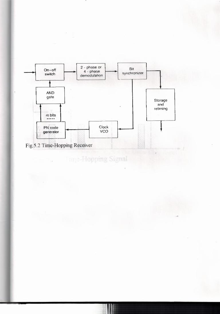
2 - phase or Bit On-off 4 - phase - synchronizer - switch demodulation
L..
t ~ AND gate
Storage and
' ' re timing
m bits ..... i Clock PN code
generator vco
Fig.5.2 Time-Hopping Receiver

'"" T, •. ~ I I
T, -~- I M~ I
I
Fig. 5. 3 A Time-Hopping Signal

Frequency
T--------- 8
l_ t,
'---___JL.__ ..___ Time Fig. 5. 4 The Linear Chirp Signal ,, 12

CONCLUSION
1- In chapter 1, is described elements of satellite communication system.
2- Chapter 2, is devoted to present satellite orbits and its description.
3- Chapter 3, presents the fundamental knowledge about spread
spectrum modulation.
4- Chapter 4, gives information about slow FH spread-spectnun '·
system.
5- Chapter 5, presents PH spread-spectrum system.
6- Chapter 6, includes method of multiple access of satellite
communication system, which in particular is considered as CDMA.
In the plan of realization was implemented digital generator
(generates 12 8 binary signals) and phase shift keying modulator using
modern integrated circuits.
I hope this project will be useful for students and engmeers,
specialized in spread-spectrum communication system.
The whole plan was realized on breadboard and can be used in the
laboratory of telecommunication and data communication.
64

1- George R. Cooper (1986), Clare D. McGillem, "Modem
communications and Spread-Spectrum", McGraw-Hill, Inc.
2- John G. Proakis (1995), "Digital Communication", 3rd Edition,
McGraw-Hill, Inc.
3- Louis E. Frenzel (1994 ), " Communication Electronics", 2nd Edition,
McGraw-Hill, Inc.
4- Masoud Salehi, Jhon G. Proakis (1994 ), "Communication Systems
Engineering", Prentice-Hall, Inc.
5- Simon Haykin (1988), "Digital Communications", John Wiley & Sons,
Inc.
6- Tri T. Ha. "Digital Satellite Communications" , 2nd Edition, McGraw
Hill, Inc.

AWGIN: Additive White Gaussian Noise
BSS: Broadcasting Satellite Service
b/s: Bit per Second
CCIR: International Radio Counsultative Committee
CDMA: Code Division Multiple-Access
dB: Decibel
DS: Direct Sequence
DS/BPSK: Direct-Sequence spread Binary Phase-Shift Keying
EHF:
ESA:
FDMA:
FH:
Extreme High Frequency
European Space Agency
Frequency Division Multiple-Access
Frequency-Hopping
FH/MFSK: Frequency-Hop Spread M-ary Frequency-Shift Keying
FSK: Frequency-Shift Keying
GPS: Global Positioning System
HF: High Frequency
HZ: Hertz
IF: Intermediate Frequency
INTELSAT:Intemational Telecommunications Satellite Organization.

ITU: International Telecommunication Union
LF: Low Frequency
LNA: Low-Noise Amplifier
LPF: Low Pass Filter
MF: Medium Frequency
NASA: National Aeronautics and Space Administration
PG: Processing Gain
PN: Pseudonoise
PSK: Phase-ShiftKeying
RF: Radio Frequency
SHF: Super High Frequency
STS: Space Transport System
TOMA: Time Division Multiple-Access
TDRSS: Telecommunication Data Relay Satellite System
TH: Time-Hopping
UHF: Ultrahigh Frequency
VHF: Very High Frequency - VLF: Very Low Frequency
WARC: World Administrative Radio Frequency


••