
CR Wideband Spectrum Sensing Baseband Progress Report 05/29/2009

ELEC-E7220 Radio Resource andSpectrum Management 5 cr
Prof. Riku JänttiDepartment of Communications and Networking
E-mail: [email protected]
Spring 2016

2
Radio Resource Management• Radio spectrum is a scarce resource that should be
utilized as efficiently as possible. Consequently, thespectrum must be shard among many users.
• In practice, all sharing (multiple access) techniquescauses interference among the users.
• The objective of Radio Resource Management is tocontrol the division of resources (power, time slots,frequency channels, spreading codes etc.) among theusers such that– The quality of service demands of the users are
satisfied (according to SLA)– The spectral and energy efficiency is maximized– Interference is mitigated– Operator revenue is maximized

Spectrum Management• Spectrum is allocated to different use based on licenses
controlled by national regulators
• When spectrum is shared among multiple systems theirmutual interference need to be controlled.
23.2.2016 3

Coure overview• Learning Outcomes
The student should understand the principles of sharingthe spectrum among the users and how to mitigate themulti-user interference via resource control such thatquality of service constraints are met while thespectrum efficiency is maximized.
23.2.2016 4
Spring 2016 OutlineLectures & exercisesPart I: MAC1. Contention based MAC & Random access2. Fairness & scheduling, energy efficiencyPart II: System aspects3. 5G (Ultra dense networks, multiuser MIMO)4. C-RANPart III: Spectrum sharing between systems5. Spectrum sharingGroup workLearning diary
Homework and learning diary are to be done individually,group work is done in a group of two to three persons.
2/23/2016 5

Grading• Grading rule:
HW Home work grade (rounded average)GW Group work gradeLD Learning diary grade
23.2.2016 6
( )1
2 4roundGrade HW GW LDæ ö
= × ×ç ÷è ø

Lecture 1. Multiple access /Randomaccess
8
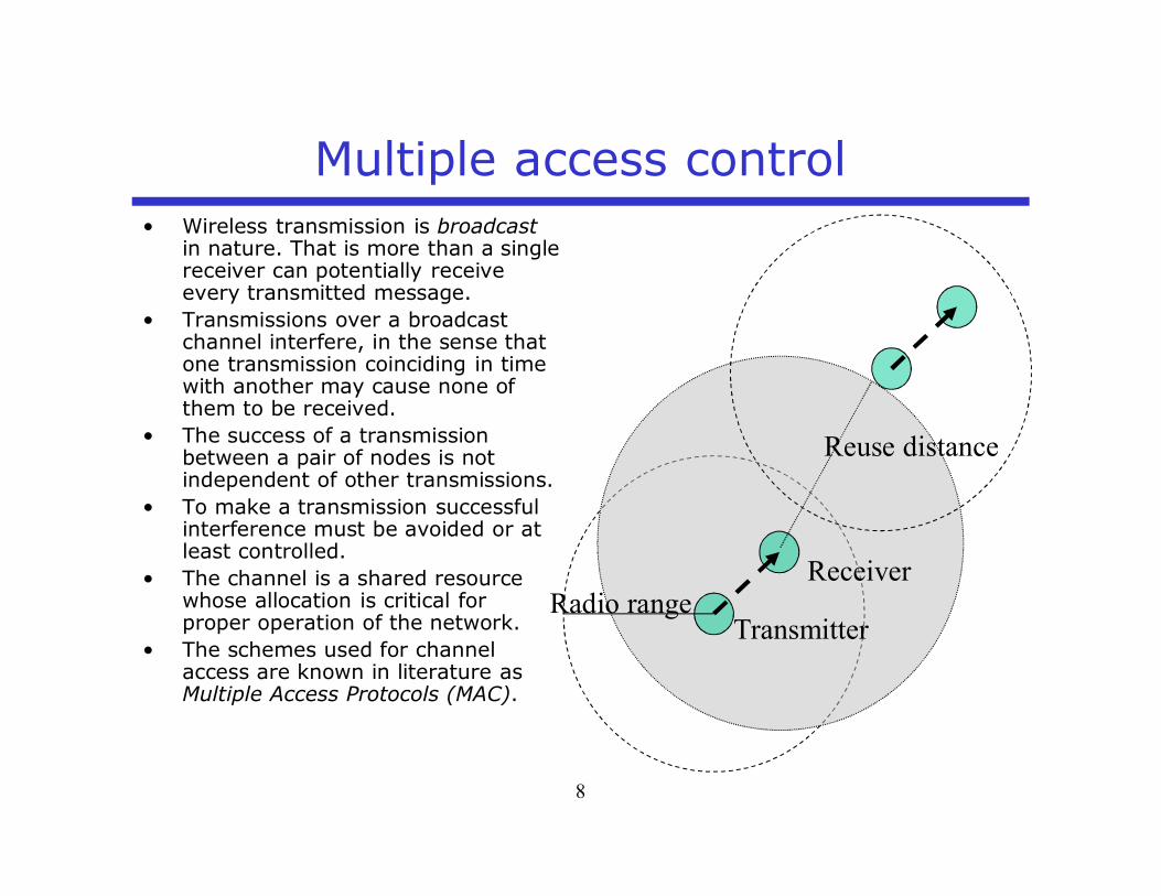
Transmitter
ReceiverRadio range
Multiple access control• Wireless transmission is broadcast
in nature. That is more than a singlereceiver can potentially receiveevery transmitted message.
• Transmissions over a broadcastchannel interfere, in the sense thatone transmission coinciding in timewith another may cause none ofthem to be received.
• The success of a transmissionbetween a pair of nodes is notindependent of other transmissions.
• To make a transmission successfulinterference must be avoided or atleast controlled.
• The channel is a shared resourcewhose allocation is critical forproper operation of the network.
• The schemes used for channelaccess are known in literature asMultiple Access Protocols (MAC).
Reuse distance

S-72.3235 NetworkAccess
9
Medium access control protocols• The task of the Medium/Multiple Access Control (MAC)
protocol is to divide the resources between the radiolinks such that– Interference is avoided or kept at controlled level– Utilization of the radio resources is maximized– Quality of service QoS differentiation among the flow
classes is achieved– Fairness inside a QoS class is maintained

S-72.3235 NetworkAccess
10
Medium access control protocols• The operation of the MAC protocol can be
– Centralized such that single entity controls theresource division among the radio links leading toconflict free access
– Decentralized such that each link makestransmission decisions independently leading tocontention based access
• Contention schemes differ in principle from conflict-freeschemes– A transmitting user is not guaranteed to be
successful.– The protocol must prescribe a way to resolve
conflicts once they occur so that all messages areeventually transmitted successfully.

S-72.3235 NetworkAccess
11
Conflict free access• In conflict free protocols, the resource allocation can be
– Static - not dependent on the traffic or channelconditions (TDMA, FDMA, F/TDMA, OFDMA, CDMA,OFCDMA,…)
– Dynamic – based on demand and/or channelconditions• Token passing (Wireless HART)• Channel reservation (satellite systems,
IEEE802.15.4 Beacon mode,…)• Dynamic scheduling (GPRS, WCDMA, WiMAX,
LTE…)• Channel dependent “opportunistic” scheduling
(e.g. CDMA2000 1xEV-DO/DV, HSDPA, LTE)

S-72.3235 NetworkAccess
12
Contention based access• In contention based protocols, the conflicts caused by colliding
packets (interference) must be resolved. Conflict resolutionmethods can be divided into– Static - the actual behavior is not influenced by the
dynamics of the system. The transmission schedule for theinterfering users can be
• Fixed: based on node IDs or priorities• Probabilistic: schedule is chosen from a fixed
distribution (p-persistent CSMA)– Dynamic – the actual behavior of the system depends
system dynamics.• Transmission schedule could be determined by the time
of the arrival• Probabilistic: Transmission schedule depends on the
number of colliding packets (BEB in IEEE802.3 andIEEE802.11)

S-72.3235 NetworkAccess
13
Classification of MAC protocolsMedium Access
Protocols
Contention Conflict free
DynamicResolution
StaticResolution
DynamicResolution
StaticResolution
Time ofArrival
Proba-bilistic
NodeID/
priorities
Proba-bilistic
Reser-Vation
&Schedu-
ling
Tokenpassing
Fixedresource
allocation
Oppor-tunistic

S-72.3235 NetworkAccess
14
Medium access control protocols• The issues affecting the performance of the channel access
– Connectivity• Can all the nodes hear each other or are there hidden terminals?• What is the network topology? Single hop, multi-hop (mesh/ad hoc)
– Channel type• What is the required Signal-to-Interference ratio for correct reception? Is there
possibility for capture in case of collisions?• Do protocol messages get lost due to fading?
– Synchronism• Is the network synchronized, i.e. slotted or can transmissions start and end at
arbitrary time instances.– Feedback information
• Can collisions be detected? Can the colliding nodes be identified?• How much information can be shared among the nodes?• Is correct reception acknowledged by the receiver?
– Traffic• Is the message size fixed or does it vary? Is packets generated randomly or with
steady rate? Can transmission buffers assumed to be saturated (TCP tends tosaturate buffers) or are they likely to be empty at times?
– User population• Is the number of users fixed or random? Can it be known by the system?
– Buffering capability• How many packets can the nodes buffer? Will packets be lost due to buffer
overflow?

Contention based methods• Wireless personal and local area networks
– No centralized control.– MAC protocol is needed to enable co-existence and
sufficient reusedistance– MAC protocols utilize carrier sensing
• Random access channels in cellular systems– A random-access channel (RACH) is a shared
channel used by user equipment to access themobile for call set-up or sometimes also for burstydata transmission.
– Carrier sensing is not possible. Hence, the terminalsattempt transmission when they need to. This leadsto ALOHA
2/23/2016 15

ALOHA
23.2.2016 17
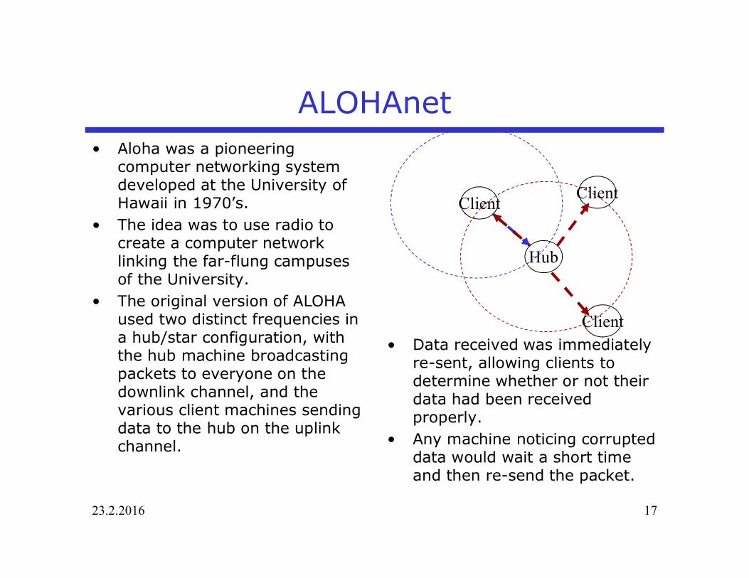
• Data received was immediatelyre-sent, allowing clients todetermine whether or not theirdata had been receivedproperly.
• Any machine noticing corrupteddata would wait a short timeand then re-send the packet.
ALOHAnet• Aloha was a pioneering
computer networking systemdeveloped at the University ofHawaii in 1970’s.
• The idea was to use radio tocreate a computer networklinking the far-flung campusesof the University.
• The original version of ALOHAused two distinct frequencies ina hub/star configuration, withthe hub machine broadcastingpackets to everyone on thedownlink channel, and thevarious client machines sendingdata to the hub on the uplinkchannel.
Hub
ClientClient
Client

23.2.2016 18
Infinite user population• Users will generate packets according to Poisson
process• The aggregate packet arrival rate generated by the
users is l

23.2.2016 19
Pure Aloha
Station A
Station B
0t T+0t 0 3t T+0 2t T+
The packet generated by station B collides ifany station generates a packet on the time intervalt0<t<t0+2T
If station has a packet it will immediately try to transmit it
Packet length is T

23.2.2016 20
Pure Aloha• Packets arrive to the system with intensity• Packets collide with probability p• In case of collision, the packet will be retransmitted
after random back-off time• Aggregate of new packets and failed packets returning
to the transmitter buffer is still a Poisson process withintensity
ål ( ) 11g p l= -
2l
1 2l l l= +
l
m 2 1pl l=
( ) 11g p l l= - =

23.2.2016 21
Pure Aloha• Packets arrival process is Poisson with intensity g
packets per second.• Transmission time of the packet is T• Probability that k packets arrive in time window Dt
• Probability that there is no collision is equal to theprobability that no other packets arrive during the timeinterval :
• Normalized load, average number of arrivals in time TG=gT
• Throughput per time T
{ } ( )Pr arrivals in!
kg t g t
k t ek
- D DD =
0 0 2t t t T< £ +{ } { } 2Pr no collision Pr 0 arrivals in 2 g TT e-= =
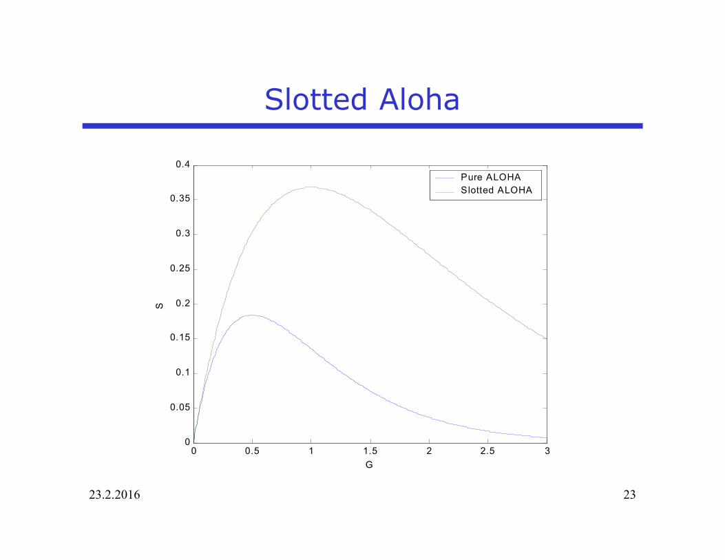
2GS Ge-=

23.2.2016 22
Slotted Aloha• Time is slotted. Transmissions in a given slot can collide
only if more than one packet arrived during theprevious slot.
GS Ge-=
23.2.2016 23
Slotted Aloha
0 0.5 1 1.5 2 2.5 30
0.05
0.1
0.15
0.2
0.25
0.3
0.35
0.4
G
S
Pure ALOHASlotted ALOHA

23.2.2016 24
Effect of bursty traffic• Bursty arrival in Aloha increases the throughput, since
occasionally the arrival rate is decreased leading to lowcollision probability
10-2 10-1 100 101 102 1030
0.1
0.2
0.3
0.4
0.5
0.6
0.7
Thro
ughp
ut
Offered traffic
MMPP-aMMPP-bPP
lT
a=0.9b=0.1MMPP-a: l2=10l1MMPP-b: l2=0,1l1
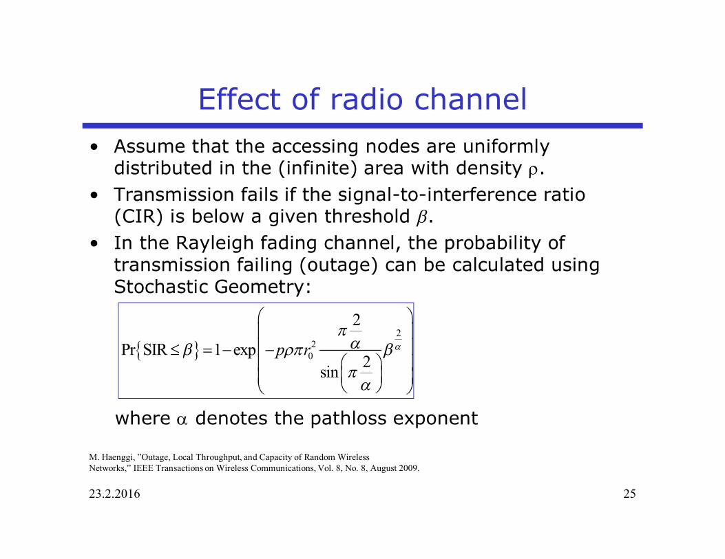
Effect of radio channel• Assume that the accessing nodes are uniformly
distributed in the (infinite) area with density r.• Transmission fails if the signal-to-interference ratio
(CIR) is below a given threshold b.• In the Rayleigh fading channel, the probability of
transmission failing (outage) can be calculated usingStochastic Geometry:
where a denotes the pathloss exponent
23.2.2016 25
{ }2
20
2
Pr SIR 1 exp2sin
p r ap
ab rp bp
a
æ öç ÷ç ÷£ = - -
æ öç ÷ç ÷ç ÷è øè ø
M. Haenggi, ”Outage, Local Throughput, and Capacity of Random WirelessNetworks,” IEEE Transactions on Wireless Communications, Vol. 8, No. 8, August 2009.

Outage probability• Mean number of interferes in a disc of radius r0 around
23.2.2016 26
20K p rrp=

Effect of radio channel• If the physical layer tolerate low SIR (e.g. use spreading
codes), the ALOHA system performance can beincreased.
23.2.2016 27

Contention based Random Access in LTE• In LTE Contention based random
Access Procedure is utilized for initialaccess to the network
• The actual Physical Random AccessChannel (PRACH) transmission is anOFDM-based reconstruction of aZadoff-Chu sequence in the timedomain. The OFDM modulator is usedto position the Zadoff-Chu sequence inthe frequency domain (i.e. to place the6RBs of PRACH transmission in the 6consecutive RBs starting from someparticular physical resource.
• If more than one user pick the samesequence, collision will happen.Otherwise, the eNodeB will provideRandom Access Response message.
• The Preamble transmission resemblesmulti-channel ALOHA MAC protocol.
23.2.2016 28

Contention based Random Access in LTE
• Cellular systems not well suited for short messages– RACH capacity– Large protocol overhead (signaling)
• New protocols are needed to support future massiveMachine Type Communications
23.2.2016
29
Poisson traffic. Packet interarrival time 30 s, 256 and 1024 bit packet sizes
5000 devices / km2
M. Gerasimenko, V. Petrov, O. Galina, S. Andreev and Y. Koucheryavy, ”Impact of machine-type communications onEnergy and delay performance of random access channel in LTE-advanced,” Transactions on emerging telecommunicationTechnologies, April 2013.

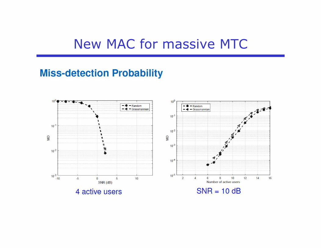
New MAC for massive MTC
• MTC traffic– Large number of devices– Low activity– Small message size
• Proposed RACH scheme:– Device register using
normal LTE RACHprocedure.
– Maintain synchronicityand timing advance.
– Certain LTE RB reservedfor MTC contention basedaccess
– Reduced latency: Jointdevice activityrecognition, channelestimation and datareception.
– Multi-user detection
Y. Beyene, C. Boyd, K. Ruttik, C. Bockelmann, O. Tirkkonen and R. Jäntti, “Compressive Sensing for MTC in New LTE Uplink Multi-User Random Access Channel,” In Proc. IEEEAfricon 2015, Addis Ababa, Ethiopia, 14-17 September 2015.

New MAC for massive MTC

New MAC for massive MTC

New MAC for massive MTC
New MAC for massive MTC

New MAC for massive MTC
Y. Beyene, N. Malm, J. Kertula, L. Zhou, K. Ruttik, R. Jäntti, O. Tirkkonen and C. Bockelmann, ” Spectrum Sharing for MTC Devices in LTE”, Demo, In Proc.IEEE DySPAN 2015, Stockholm, Sweden, September 29 – October 2, 2015.

CSMA/CA& IEEE802.11 DCF Performance

23.2.2016 37
IEEE802.11 DCF Basic Access Mechanism
• A station with a new packet to transmit monitors the channelactivity.– If the channel is idle for a period of time equal to a
distributed interframe space (DIFS), the station transmits.– If the channel is sensed busy (either immediately or during
the DIFS),• the station persists to monitor the channel until it is
measured idle for a DIFS.• The station generates a random backoff interval before
transmitting to minimize the probability of collision withpackets being transmitted by other stations. (CA = CollisionAvoidance)
• In addition, to avoid channel capture, a station must wait arandom backoff time between two consecutive new packettransmissions, even if the medium is sensed idle in the DIFStime

23.2.2016 38
IEEE802.11 DCF Basic Access Mechanism
• For efficiency reasons, DCF employs a discrete-time backoffscale.– The time immediately following an idle DIFS is slotted, and
a station is allowed to transmit only at the beginning ofeach slot time.
– The slot time size, s, is set equal to the time needed atany station to detect the transmission of a packet fromany other station.
• DCF adopts an exponential backoff scheme. At each packettransmission, the backoff time CW is uniformly chosen in therange (CWmin,CWmax).
• The value CW is called contention window, and depends onthe number of transmissions failed for the packet. At the firsttransmission attempt, is set equal to a value CWmin calledminimum contention window. After each unsuccessfultransmission, is doubled, up to a maximum value CWmax.

23.2.2016 39
IEEE802.11 DCF Basic Access Mechanism
• The backoff time counter is decremented as long as thechannel is sensed idle, “frozen” when a transmission isdetected on the channel, and reactivated when the channel issensed idle again for more than a DIFS.
• The station transmits when the backoff time reaches zero.• Since the CSMA/CA does not rely on the capability of the
stations to detect a collision by hearing their owntransmission, an ACK is transmitted by the destination stationto signal the successful packet reception.
• The ACK is immediately transmitted at the end of the packet,after a period of time called short interframe space (SIFS).
• The SIFS (plus the propagation delay) is shorter than a DIFS,no other station is able to detect the channel idle for a DIFSuntil the end of the ACK.

23.2.2016 40
IEEE802.11 DCF Basic Access Mechanism
• If the transmitting station does not receive the ACK within aspecified ACKTimeout, or it detects the transmission of adifferent packet on the channel, it reschedules the packettransmission according to the given backoff rules.
Station A
Station BACK
DIFSACK
DIFS
0123456
Medium busy
w w-1 w-2
s
Packet A
Packet BPacket B
DIFS
DIFSSIFS
SIFS
Slot time: Slot time:frozen backoff time

23.2.2016 41
IEEE802.11 DCF RTS-CTS Access Mechanism
• A station that wants to transmit a packet, waits until the channel is sensedidle for a DIFS, follows the backoff rules explained above, and then,instead of the packet, preliminarily transmits a special short frame calledrequest to send (RTS).
• When the receiving station detects an RTS frame, it responds, after aSIFS, with a clear to send (CTS) frame.
• The transmitting station is allowed to transmit its packet only if the CTSframe is correctly received.
• The frames RTS and CTS carry the information of the length of the packetto be transmitted. This information can be read by any listening station,which is then able to update a network allocation vector (NAV) containingthe information of the period of time in which the channel will remainbusy.
n A and C want to send to Bn A sends RTS to Bn B sends CTS to An C “overhears” CTS from Bn C waits for duration of A’s
transmissionA B CRTS
CTSCTS
CBA
23.2.2016 42
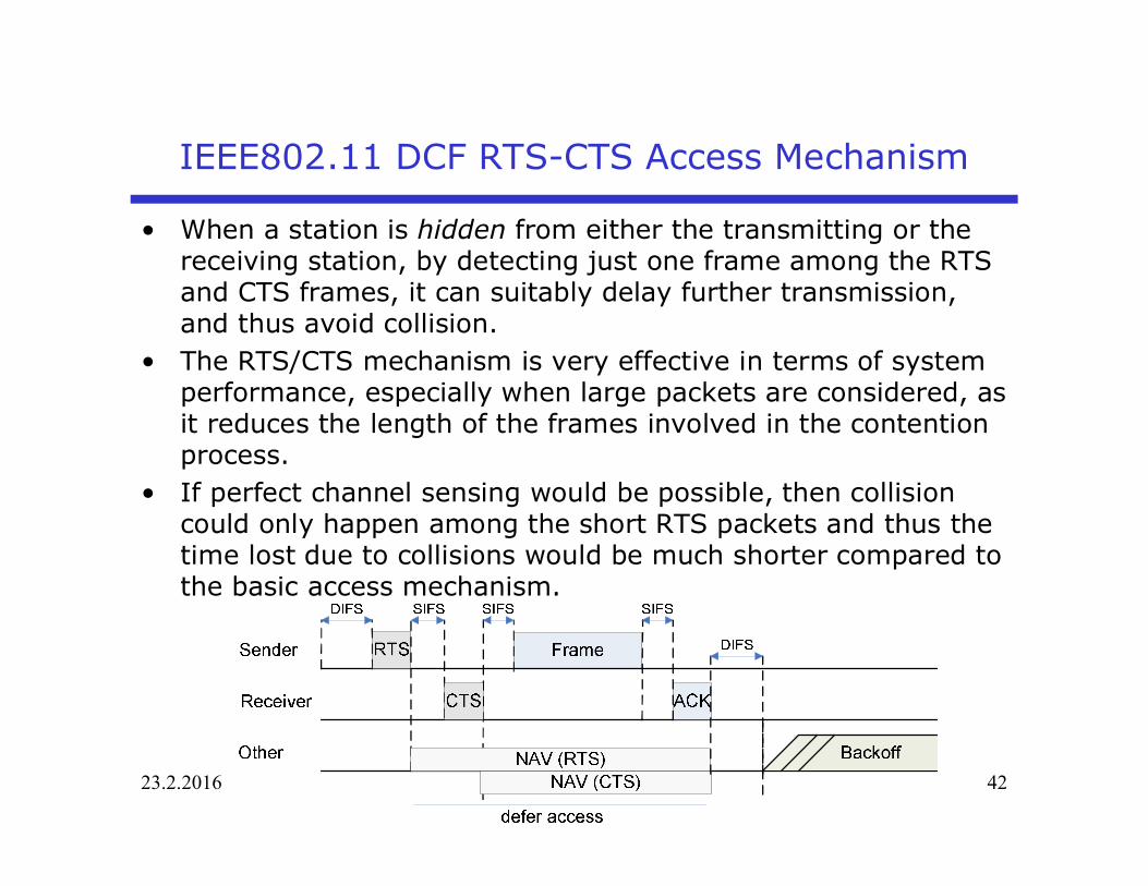
IEEE802.11 DCF RTS-CTS Access Mechanism
• When a station is hidden from either the transmitting or thereceiving station, by detecting just one frame among the RTSand CTS frames, it can suitably delay further transmission,and thus avoid collision.
• The RTS/CTS mechanism is very effective in terms of systemperformance, especially when large packets are considered, asit reduces the length of the frames involved in the contentionprocess.
• If perfect channel sensing would be possible, then collisioncould only happen among the short RTS packets and thus thetime lost due to collisions would be much shorter compared tothe basic access mechanism.

23.2.2016 43
IEEE802.11 DCF Performance• Consider saturated traffic conditions, in which all the n
users always have packet ready for transmission.• The channel is assumed to be perfect (no packet drop,
no capture)• Let t denote the probability that a given station
transmits a packet in randomly chosen slot time.• A collision happens with probability p.• In order to make the analysis tractable, we make the
approximation that the collision probability is constantand the same for all stations regardless of thetransmissions already suffered.

23.2.2016 44
IEEE802.11 DCF Performance• Let b(t) denote the backoff time counter for a given
station at discrete slot time t. The slot time correspondsto the time instances when the backoff counter value ischanged.
Station A
Station BACK
DIFSACK
DIFS
0123456
Medium busy
w w-1 w-2
s
Packet A
Packet BPacket B
DIFS
DIFSSIFS
SIFS
Slot time: Slot time:frozen backoff time
Station A
Station BACK
DIFSACK
DIFS
0123456
Medium busy
w w-1 w-2
s
Packet A
Packet BPacket B
DIFS
DIFSSIFS
SIFS
Slot time: Slot time:frozen backoff time
t t+1 t+2 t+3 t+4 …

23.2.2016 45
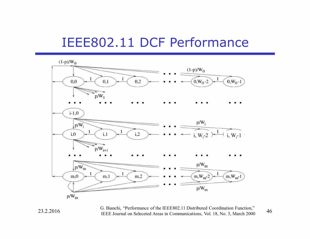
IEEE802.11 DCF Performance• Let us define
– W=CWmin
– CWmax=2m CWmin
– Wi=2iW, i=0,1,2,…m• Let s(t) denote the backoff stage i of the station at slot
time t.• Since the collision probability p is assumed to be
independent of the number of retransmission attempt,we can now model the behavior of the MAC protocol astwo dimensional Markov chain.
23.2.2016 46
IEEE802.11 DCF Performance
G. Bianchi, “Performance of the IEEE802.11 Distributed Coordination Function,”IEEE Journal on Seleceted Areas in Communications, Vol. 18, No. 3, March 2000
i, Wi-2 i, Wi-1

23.2.2016 47
IEEE802.11 DCF Performance• Let P{i,k|j,l}=Pr{s(t+1)=i,b(t+1)=k|s(t)=j,b(t)=l}• The state transition probabilities in the Markov chain
can thus be written as{ }
{ } ( )
{ }
{ }
00
Pr , , 1 1, (0, 2), (0, )
1Pr 0, ,0 1 , (0, 1), (0, )
1Pr , 1,0 , (0, 1), (1, )
1Pr , ,0 , (0, 1)
i
ii
mm
i k i k k W i m
k i p k W i mW
i k i p k W i mW
m k m p k WW
+ = Î - Î
= - Î - Î
- = Î - Î
= Î -

23.2.2016 48
IEEE802.11 DCF Performance• Let
be the stationary state distribution of the Markov chain.• Consider stage 0<i<m
• It follows from (1) that
{ }, lim Pr ( ) , ( ) , (0, 1), (1, )i k t ib s t i b t k k W i m®¥= = = Î - Î
i-1,0
i,1i,0 i,Wi-11
p
1-pp/Wi
Flow out = Flow in
, 1 1,0
, 2 1,0 , 1 1,0
, 1,0
1
1 2
i
i i
i W ii
i W i i W ii i
ii k i
i
b p bW
b p b b p bW W
W kb p bW
- -
- - - -
-
=
= + =
-=
M
,0 1,0 ,0 0,0 , 1,2,..., 1ii i ib pb b p b i m-= Þ = = -
(1)
(2)

23.2.2016 49
IEEE802.11 DCF Performance• For the last stage we have
• It follows from (2) and (3) that
m-1,0
m,1m,0 m,Wm-111-pp/Wm
p/Wm
Flow out = Flow in
( )
( )
( )
, 1 1,0 ,0 1,0 ,0
, 2 1,0 ,0 , 1 1,0 ,0
, 1,0 ,0
1 1 1
1 1 2
m
m m
m W m m m mm m m
m W m m m W m mm m m
mm k m m
m
b p b p b p b bW W W
b p b p b b p b bW W W
W kb p b bW
- - -
- - - -
-
= + = +
= + + = +
-= +
M
( ) 1,0 1,0 ,0 ,0 1,0 0,0 0,01 1 1
mm
m m m m mp p pb p b b b b p b b
p p p-
- -= + Þ = = =- - -
(3)
(4)
23.2.2016 50
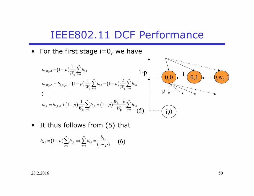
IEEE802.11 DCF Performance• For the first stage i=0, we have
• It thus follows from (5) that
0,10,0 0,W0-11
p
1-p
i,0
( )
( ) ( )
( ) ( )
0
0 0
0, 1 ,000
0, 2 0, 1 ,0 ,00 00 0
00, 0, 1 ,0 ,0
0 00 0
11
1 21 1
11 1
m
W ii
m m
W W i ii i
m m
k k i ii i
b p bW
b b p b p bW W
W kb b p b p bW W
-=
- -= =
+= =
= -
= + - = -
-= + - = -
å
å å
å å
M
( ) ( )0,0
0,0 ,0 ,00 0
11
m m
i ii i
bb p b b
p= =
= - Þ =-å å
(5)
(6)

23.2.2016 51
IEEE802.11 DCF Performance• The state probabilities must sum to 1
• The probabilities must sum to 1
, 1,0, ,0 0,0
,0 0,0
ii k i ii i
i i k ii i i
i
W kb p b W k W kW b b p bW Wb p b
-
-ì = - -ï Þ = =íï =î
( ) ( )
( )( )
1 1 1
, ,0 ,0 ,00 0 0 0 0 0 0
10,0
,00 0
0,0
12
22 1 12 12 2 1 1
2(1 2 )(1 )(1 2 )( 1) 1 2
i i iW W Wm m m mi i i
i k i i ii k i k i k ii i
mim mi
ii i
m
W k W k Wb b b bW W
b pWb p Wp p
p pbp W pW p
- - -
= = = = = = =
-
= =
- - += = =
æ öæ ö+= = + + =ç ÷ç ÷ ç ÷- -è ø è ø
- -Þ =
- + + -
åå åå å å å
å å
1
( 1)2
K
k
K Kk=
+=å
1
0
11
NNn
n
xxx
-
=
-=
-å

23.2.2016 52
IEEE802.11 DCF Performance• We can now express the probability t that a station
transmits during a randomly chosen slot time. Thetransmission occurs when the backoff time counter isequal to zero, regardless of the backoff state, hence
• The probability that there is collision is that more thanone user tries transmission at the same slot time:
( )( )0,0
,00
2(1 2 )1 (1 2 )( 1) 1 2
m
i mi
b pbp p W pW p
t=
-= = =
- - + + -å
( ) 11 1 np t -= - -

23.2.2016 53
IEEE802.11 DCF Performance• Probability that at least one user transmits
• Probability of successful transmission conditioned thattransmission takes place
( )1 1 ntrP t= - -
{ }{ }{ }
( )( )
1
Pr exactly one user transmit at least one user transmit
Pr exactly one user transmit 1Pr at least one user transmit 1 1
s
n
n
P
nt t
t
-
=
-= =
- -

23.2.2016 54
IEEE802.11 DCF Performance• The throughput is
where– d is the slot length (propagation delay)– Ps is the probability of successful transmission in a busy
period– Ptr is the probability that there is transmission at given slot– E{P} is the expected length of the packet– Ts is the average time the channel is busy in case of
successful transmission– Tc is the is the time the channel is busy in case of collision
{ }( ) ( )
E1 1
tr s
tr tr s s tr s c
P P PS
P P PT P P Ts=
- + + -

23.2.2016 55
IEEE802.11 DCF Performance• Basic access method:
where H denotes the totallength of PHY and MACheaders
• RTS-CTS handshake
E{ }
E{ }
s
c
T H P SIFSACK DIFS
T H P DIFS
ss
s
= + + ++ + += + + +
E{ }s
c
T RTS SIFS CTS SIFSH P SIFS
ACK DIFST RTS DIFS
ss
ss
= + + + + ++ + +
+ + += + +
G. Bianchi, “Performance of the IEEE802.11 Distributed Coordination Function,”IEEE Journal on Seleceted Areas in Communications, Vol. 18, No. 3, March 2000

23.2.2016 56
IEEE802.11 DCF Performance• The throughput can be written as
Hence, the throughput is maximized if
is maximized.Maximum occurs when
{ }( ) ( )
E1 1tr tr s c
ss
PS
P P P TT
Ps
=- + -
+
( ) ( )( )
( )
11
1 1 1 1
ns
nc c ctr tr s
nPT T TP P P
t t
td d d
--=
æ ö- + - - - -ç ÷è ø
( ) ( )( )( )1 1 1 0n ncT nt t td
- - - - - =

23.2.2016 57
IEEE802.11 DCF Performance• For low load
• The transmit probability that maximizes throughput isgiven by
• Hence, the throughput depends only on the networksize n and on the system parameters m and W.
( )
( )*
2 1 11 1
1 12
c
c c
Tn n
nT Tn n
d
t
d d
æ ö+ - -ç ÷è ø -
= »æ ö- -ç ÷è ø
1t <<
( ) 2( 1)1 12
n n nnt t t-- » - +

23.2.2016 58
IEEE802.11 DCF Performance• The transmission probability depends on the parameters
m and W which should be tuned such that
• For m=0, we have
Hence, the window size should be selected as
That is, the optimal performance is obtained when thewindow size depends on the number of users and theaverage transmission time of the packets.
( )( )2(1 2 ) 1
(1 2 )( 1) 1 22
mc
pTp W pW p n
t
d
-= »
- + + -
2( 1)W
t =+
2 cTW nd
»

Impact of contention window length• A simple simulation of
DCF– 802.11a and fixed CW for
an increasing number ofSTAs,
– Under saturation
– For a given number ofSTAs,too small CW yieldsmany collisionstoo large CW yields manyidle slots
– Cost for a collision is highsince the whole packet istransmitted
– ARQ is needed to detectthe collisions
– Capacity is wasted
23.2.2016 59
0 50 100 1500.5
0.55
0.6
0.65
0.7
0.75
0.8
0.85
0.9
0.95
1
Number of users
Cha
nnel
Util
izat
ion
CW = 127CW = 255CW = 511CW = 1023
contributed by Thomas Nilsson, Umeå University

23.2.2016 60
IEEE802.11 DCF Performance• In practice, it is very difficult to estimate n.• BEB can be viewed as an attempt to estimate the
optimal window size, but it does not do a very good jobfor large n.
0 50 100 150 200 250 300 350 400 450 5000.4
0.5
0.6
0.7
0.8
0.9
1
number of users
chan
nelu
tiliz
atio
n 802.11 BEB
802.11 CWopt
• A comparison between– 802.11 BEB (normal)– 802.11 CWopt, uses
the optimal CW– BEB used in 802.11 is
far from optimal,– especially for large
number of users– for few stations the
result is satisfactory
IEEE802.11a
contributed by Thomas Nilsson, Umeå University

References• G. Bianchi, “Performance of the IEEE802.11 Distributed
Coordination Function,” IEEE Journal on Selected Areasin Communications, Vol. 18, No. 3, March 2000
More elaborated model with retry limit can be found from
• Y. Xiao, “Performance Analysis of Priority Schemes forIEEE 802.11 and IEEE 802.11e Wireless LANs,” IEEETransactions on Wireless Communications, Vol. 4, No.4, July 2005
23.2.2016 61

IEEE802.11 DCF in Radio Channel• BEP reduces the density of active transmitters even
further compared to basic CSMA
23.2.2016 62
Effectivedensity
Thick blue line = CSMAhttp://arxiv.org/abs/1211.7139


![Predicting Spectra: [Cr(NH3 6)]Cl3huntresearchgroup.org.uk/teaching/teaching_spectroscopy...2 Figure 1 Tanabe-Sugano diagram for d3. • Sketch a possible UV-vis spectrum. o [Cr(NH](https://static.fdocuments.net/doc/165x107/5e23b08063eaf24ccc482f8c/predicting-spectra-crnh3-6-2-figure-1-tanabe-sugano-diagram-for-d3-a.jpg)


