Effect of tempering temperatures on the mechanical ... · Effect of tempering temperatures on the...
14
Materials Science and Engineering A318 (2001) 197 – 210 Effect of tempering temperatures on the mechanical properties and microstructures of HSLA-100 type copper-bearing steels S.K. Dhua a *, Amitava Ray a , D.S. Sarma b a Research and Deelopment Centre for Iron and Steel, Steel Authority of India Ltd., Ranchi 834002, India b Department of Metallurgical Engineering, Banaras Hindu Uniersity, Varanasi 221005, India Received 14 June 2000; received in revised form 23 February 2001 Abstract Two copper-bearing high-strength low-alloy (HSLA) steels with chemistry similar to HSLA-100, were made on a laboratory scale, one in an air induction (100 kg) furnace and the other in a vacuum induction (50 kg) furnace. The ingots cast were hot-rolled to 25 mm thick plates which were subsequently austenitized and tempered at different temperatures (400 – 700°C) for 1 h. Evaluation of mechanical properties and microstructure of as-quenched and tempered plates revealed that substantial improvement in strength (YS-1024 and 1025 MPa; UTS-1079 and 1111 MPa for steels 1 and 2) occurred at the expense of impact toughness on tempering at 500°C owing to profuse Cu precipitation in the matrix. With increase in tempering temperature however, the notch toughness improved considerably, reaching peak values of 53 and 123 Joules (J) at −85°C for steels 1 and 2 at 650 and 700°C tempering temperatures, respectively. The partially recovered matrix and the coarsened Cu precipitates in this temperature range presumably enhanced dislocation movement and notch toughness. © 2001 Elsevier Science B.V. All rights reserved. Keywords: HSLA-100; Copper-bearing steels; Cu precipitation www.elsevier.com/locate/msea 1. Introduction Quenched and tempered medium-carbon low-alloy steels are traditionally used for engineering structures demanding high strength and toughness. Although car- bon is the prime element used for enhancing strength in these steels, it nonetheless is known to reduce weldabil- ity and impact toughness if present above a certain quantity [1]. Owing to the presence of 0.18–0.20 weight (wt.)% carbon and a high carbon equivalent of 0.8–0.9, the commonly used HY-80 and HY-100 grades of steels present difficulties in welding [1–5]. In order to over- come this problem, a new generation of low-carbon, copper-bearing HSLA steels have been developed [2 – 5]. In general, copper is perceived to be an undesirable element in steel owing to its associated hot-shortness problem. However, its judicious usage can improve the hardenability and atmoshpheric corrosion resistance of structural steels. Copper, by virtue of -copper precipi- tation, improves the strength in the HSLA class of steels without adversely affecting weldability. In the evolution of a new series of such alloys, the ASTM A 710 steel, with a composition (in wt.%) of 0.07 C, 1 Cu, 0.8 Ni, 0.7 Cr, 0.2 Mo and 0.04 Nb was the first to be developed [6–10]. Based on this composition, the HSLA-80 steel with a minimum yield strength (YS) of 552 MPa was developed in the 1980s for construction of hulls for naval ships and submarines [2,11]. The carbon level in this steel was kept below 0.08 wt.% as it was established that weldability was not adversely af- fected even at a higher carbon equivalent if the carbon content was restricted to 0.1 wt.% [1]. Although the HSLA-80 steel was certified by U.S. Navy for naval applications, its limitation of YS (552 MPa, maximum) made it unsuitable for use in struc- tures subjected to complex dynamic loading, as com- monly encountered in many important components of naval ships and submarines [2]. Moreover, because of its limited hardenability, the HSLA-80 steel is not * Corresponding author. Fax: +91-651-501327. E-mail addresses: [email protected] (A. Ray), [email protected] (D.S. Sarma). 0921-5093/01/$ - see front matter © 2001 Elsevier Science B.V. All rights reserved. PII:S0921-5093(01)01259-X
Transcript of Effect of tempering temperatures on the mechanical ... · Effect of tempering temperatures on the...

Materials Science and Engineering A318 (2001) 197–210
Effect of tempering temperatures on the mechanical properties andmicrostructures of HSLA-100 type copper-bearing steels
S.K. Dhua a *, Amitava Ray a, D.S. Sarma b
a Research and De�elopment Centre for Iron and Steel, Steel Authority of India Ltd., Ranchi 834002, Indiab Department of Metallurgical Engineering, Banaras Hindu Uni�ersity, Varanasi 221005, India
Received 14 June 2000; received in revised form 23 February 2001
Abstract
Two copper-bearing high-strength low-alloy (HSLA) steels with chemistry similar to HSLA-100, were made on a laboratoryscale, one in an air induction (100 kg) furnace and the other in a vacuum induction (50 kg) furnace. The ingots cast werehot-rolled to 25 mm thick plates which were subsequently austenitized and tempered at different temperatures (400–700°C) for1 h. Evaluation of mechanical properties and microstructure of as-quenched and tempered plates revealed that substantialimprovement in strength (YS-1024 and 1025 MPa; UTS-1079 and 1111 MPa for steels 1 and 2) occurred at the expense of impacttoughness on tempering at 500°C owing to profuse Cu precipitation in the matrix. With increase in tempering temperaturehowever, the notch toughness improved considerably, reaching peak values of 53 and 123 Joules (J) at −85°C for steels 1 and2 at 650 and 700°C tempering temperatures, respectively. The partially recovered matrix and the coarsened Cu precipitates in thistemperature range presumably enhanced dislocation movement and notch toughness. © 2001 Elsevier Science B.V. All rightsreserved.
Keywords: HSLA-100; Copper-bearing steels; Cu precipitation
www.elsevier.com/locate/msea
1. Introduction
Quenched and tempered medium-carbon low-alloysteels are traditionally used for engineering structuresdemanding high strength and toughness. Although car-bon is the prime element used for enhancing strength inthese steels, it nonetheless is known to reduce weldabil-ity and impact toughness if present above a certainquantity [1]. Owing to the presence of 0.18–0.20 weight(wt.)% carbon and a high carbon equivalent of 0.8–0.9,the commonly used HY-80 and HY-100 grades of steelspresent difficulties in welding [1–5]. In order to over-come this problem, a new generation of low-carbon,copper-bearing HSLA steels have been developed [2–5].In general, copper is perceived to be an undesirableelement in steel owing to its associated hot-shortnessproblem. However, its judicious usage can improve thehardenability and atmoshpheric corrosion resistance of
structural steels. Copper, by virtue of �-copper precipi-tation, improves the strength in the HSLA class ofsteels without adversely affecting weldability. In theevolution of a new series of such alloys, the ASTM A710 steel, with a composition (in wt.%) of 0.07 C, 1Cu, 0.8 Ni, 0.7 Cr, 0.2 Mo and 0.04 Nb was the first tobe developed [6–10]. Based on this composition, theHSLA-80 steel with a minimum yield strength (YS) of552 MPa was developed in the 1980s for constructionof hulls for naval ships and submarines [2,11]. Thecarbon level in this steel was kept below 0.08 wt.% as itwas established that weldability was not adversely af-fected even at a higher carbon equivalent if the carboncontent was restricted to �0.1 wt.% [1].
Although the HSLA-80 steel was certified by U.S.Navy for naval applications, its limitation of YS (552MPa, maximum) made it unsuitable for use in struc-tures subjected to complex dynamic loading, as com-monly encountered in many important components ofnaval ships and submarines [2]. Moreover, because ofits limited hardenability, the HSLA-80 steel is not
* Corresponding author. Fax: +91-651-501327.E-mail addresses: [email protected] (A. Ray),
[email protected] (D.S. Sarma).
0921-5093/01/$ - see front matter © 2001 Elsevier Science B.V. All rights reserved.PII: S0 9 21 -5093 (01 )01259 -X

S.K. Dhua et al. / Materials Science and Engineering A318 (2001) 197–210198
Table 1Chemical analysis of the experimental steels (wt.%)
Steel MnC Si P S Cu Cr Mo Ni Nb Al
0.62 0.111 0.0140.026 0.013 1.73 0.58 0.68 3.37 0.03 0.0040.73 0.29 0.017 0.016 1.52 0.75 0.70 3.120.03 0.032 0.038
considered suitable for making higher thickness plates[4]. The limitations of the HSLA-80 steel led to thedevelopment of HSLA-100 steel with higher strength(YS: 690 MPa), superior toughness and weldability.This steel contains higher amounts of Ni, Cu, Mn andMo than those of earlier grades [12–18].
We had earlier investigated the structure–propertyrelationships of an industrially made HSLA-100 steelwhich was processed through vacuum degassing routeand hot-rolled to 51 mm thick plates [19]. In the presentwork, two experimental Cu-bearing HSLA steels withsimilar chemistry, but processed through air and vac-uum induction furnace routes, were investigated. Whilethe different steel making routes governed the charac-teristics of non-metallic inclusions (NMI), the mi-crostructure of plates was influenced by down-streamrolling and heat-treatment regimes. The paper eluci-dates the effect of NMI characteristics and temperingtemperatures on the microstructure and mechanicalproperties of heat-treated steel plates.
2. Experimental
Two experimental heats were made, one in a 100 kgcapacity air– induction furnace and another in a 50 kgcapacity vacuum-induction furnace. The air-inductionfurnace heat (steel�1) was cast into 300×100×100mm size ingots, whereas the vacuum-induction furnaceheat (steel�2) was cast into ingots of 100 mm diameterand 400 mm length. The chemical analyses of the twosteels are shown in Table 1.
The ingots were soaked at 1250°C for 2 h andhot-rolled into 25 mm thick plates in a 2-high experi-mental rolling mill. After hot-rolling, the plates werecooled in air. The as-rolled plates were cut in thelongitudinal-through thickness (LT) orientation into 14mm thick Charpy and tensile test blocks of suitabledimensions. For ensuring uniformity of sample loca-tion, test blocks were cut from a distance of 2–3 mmfrom the top/bottom surfaces. These test blocks wereaustenitized at 950°C for 40 min, quenched in waterand subsequently tempered at different temperaturesranging from 400–700°C for 1 h, followed by quench-ing in water. All the aforesaid heat treatments werecarried out in a salt bath furnace.
Microstructural examination of water-quenched aswell as tempered steel plates were conducted in a
‘NEOPHOT-30’ model metallurgical microscope. Forcharacterizing non-metallic inclusions, polished and un-etched specimens were used, while microstructural stud-ies were carried out on 2% nital-etched specimens.Quantitative image analysis of polished specimens wascarried out in a LEICA make, ‘Q-600’ model imageanalysis system to quantify inclusion contents. Thevolume fractions of NMI present in each specimen weredetermined by scanning around 300 fields and theaverage value was reported (Table 2). Qualitative elec-tron-probe microanalysis was carried out in a JEOLmake, ‘JCXA-733’ model electron-probe microanalyser(EPMA) to ascertain inclusion chemistry. For preciseidentification of phases, X-ray diffractometric studieswere also carried out on specimens using Mo target ina SIEMENS make, ‘D-500’ model X-raydiffractometer.
Thin foils for transmission electron microscopy wereprepared in a twin-jet electropolisher using an elec-trolytic solution of 95% glacial acetic acid and 5%perchloric acid. These foils were examined in a JEOL‘JEM-4000 EX’ transmission electron microscope(TEM) at 200 keV to observe the microstructuraldetails.
Hardness measurements were conducted in a Vicker’shardness tester under 30 kg applied load and the aver-age hardness of a particular sample was reported frommeasurements over 10 locations. Tensile testing wascarried out on 6.25 mm diameter specimens in a 10 toncapacity ‘INSTRON-1195’ model universal testing ma-chine, using a 25 mm gauge length (GL) extensometer.The tests were conducted in accordance with ASTM A370 specification. Three specimens were tested for eachheat-treatment condition and the average values werereported. Charpy impact tests were conducted usingstandard V-notch (2 mm deep notch) specimens (10×10×55 mm size) as per ASTM E 23 specification. Thetests were conducted both at ambient (25°C) and sub-zero (−20 and −85°C) temperatures. The Charpy test
Table 2Volume fraction of non-metallic inclusions in the experimental steels
Inclusion volume fraction (%)Steel
Maximum AverageMinimum
0.166 0.200.23510.090.1030.0842

S.K. Dhua et al. / Materials Science and Engineering A318 (2001) 197–210 199
Fig. 1. Variation of Yield strength, ultimate tensile strength and hardness of steels 1 and 2 with tempering temperature.
specimens for the aforesaid tests were prepared in L–Torientation and notched transverse to the plate thick-ness. The broken Charpy specimens were examined in aJEOL make, ‘JSM-840A’ model scanning electron mi-croscope (SEM) at an accelerating voltage of 20 keV tostudy fracture topography.
3. Results
3.1. Mechanical properties
3.1.1. HardnessThe average Vickers hardness values (VHN) of wa-
ter-quenched plates of steels 1 and 2 were found to be297 and 316 VHN, respectively. The correspondinghardness values decreased to 263 and 246 VHN upontempering at 700°C. For both the steels, peak hardnessvalue of 347 VHN was achieved after tempering at500°C. The hardness versus tempering temperatureplots of steels 1 and 2 are shown in Fig. 1.
3.1.2. Yield and tensile strengthIn water-quenched and tempered condition, the YS
was found to vary between 734–1024 and 670–1025MPa for steels 1 and 2, respectively. The YS was found
to be maximum at 500°C and minimum at 700°Cwithin the experimental tempering range. The variationof YS and hardness with tempering temperature in boththe steels are graphically shown in Fig. 1.
The ultimate tensile strength (UTS) of water-quenched and tempered plates varied between 872–1079 and 803–1111 MPa in steels 1 and 2, respectively.In both steels 1 and 2, peak UTS, similar to peak YS,was achieved after tempering at 500°C, while the mini-mum UTS was obtained at 700°C. Fig. 1 also depictsthe variation of UTS with tempering temperature ofsteels 1 and 2 along with hardness and YS plots.
3.1.3. Elongation and reduction-in-areaThe elongation (EL) percent of water-quenched and
tempered plates varied between 15–22 and 16–25% forsteels 1 and 2, respectively. The elongation was maxi-mum for both the steels after tempering at 650°C andminimum in the water-quenched state. Fig. 2 showstypical elongation versus tempering temperature plotsof both the steels.
The reduction-in-area (RA) percent of water-quenched and tempered plates varied between 60–69and 65–75%, respectively for steels 1 and 2. The % RAwas found to be maximum after tempering at 650°C forsteel 1, whereas for steel 2, it was maximum after 700°C

S.K. Dhua et al. / Materials Science and Engineering A318 (2001) 197–210200
tempering. The minimum values of % RA were attainedin both the steels after tempering at 450°C. The varia-tion of % RA with tempering temperature in steels 1and 2 are shown in Fig. 2.
3.1.4. Charpy impact toughnessThe Charpy V-notch (CVN) impact energy values of
the water-quenched and tempered plates of steel 1varied between 35–98 J at 25°C, 22–93 J at −20°C,and 7–53 J at −85°C. In case of steel 2 plates, theCVN energy values at the corresponding temperaturesvaried between 31–136, 26–130 and 9–123 J, respec-tively. In case of steel 1, the CVN energy was maximumafter tempering at 650°C, whereas for steel 2, it washighest after 700°C tempering. Interestingly, the mini-mum CVN energy values were obtained for both thesteels after 450°C tempering. The CVN energy versustempering temperature plots of steels 1 and 2 tested atvarious test temperatures are shown in Fig. 3(a, b),respectively.
3.2. Microstructures
3.2.1. Optical microscopyIn unetched condition, NMI in water-quenched steel
1 were found to be mostly oxysulphide stringers (Fig.4a). EPMA analysis confirmed that these stringers wereessentially complexes of MnS and Al2O3–SiO2. Fewsmall size globular oxides and lenticular sulphides werealso observed in this steel. Steel 2 on the other hand,mostly revealed small globular oxide inclusions (Fig.4b) whose EPMA analysis confirmed presence of Feand Si. In this steel, few stringers of oxysulphide inclu-sions were also observed.
The microstructures of steel 1 in water-quenchedcondition as well as after tempering at 700°C are shownin Fig. 5(a, b), respectively. The microstructure appearsto be of lath martensite in the as-quenched conditionand shows no significant difference after tempering at700°C.
3.2.2. Transmission electron microscopyTEM studies of the as-quenched steels revealed
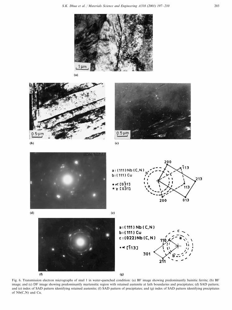
mixed microstructure of lath martensite and bainiticferrite. A typical bainitic ferrite microstructure ob-served in steel 1 is shown in Fig. 6(a). Fig. 6 (b–c) showbright-field (BF) and dark-field (DF) micrographs ofthe same steel from different martensitic regions. Themartensite laths were found to be associated with tracesof retained austenite at lath boundaries, while very fineprecipitates (approximately 10–25 nm diameter) of Cuand Nb(C,N) were also observed within the laths. Thepresence of retained austenite and the precipitates wereconfirmed by indexed selected area diffraction (SAD)patterns and are shown in Fig. 6(d–g), respectively.
The BF micrograph in Fig. 7 (a) shows typical unre-covered lath martensite structures observed in the steelstempered at 500°C. Profuse precipitation of Cu withinthe laths could be noticed in the BF and DF micro-graphs shown in Fig. 7 (b–c) which pertain to the samearea. The SAD pattern of the precipitates and thecorresponding index photograph are shown in Fig. 7(d–e), respectively. The Cu precipitates observed werearound 15–30 nm in diameter and were almost spheri-cal in shape at this tempering temperature.
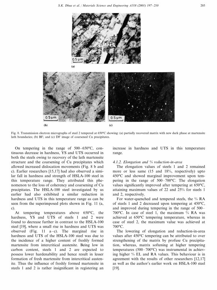
Transmission electron microscopy of the steels aftertempering at 650°C showed partially recovered matrixwith uniformly distributed Cu precipitates. Fig. 8 (a)
Fig. 2. Variation of elongation and reduction -in-area% of steels 1 and 2 with tempering temperature.

S.K. Dhua et al. / Materials Science and Engineering A318 (2001) 197–210 201
Fig. 3. (a) Variation of CVN energy of steel 1 at 25, −20 and −85°C with tempering temperature; (b) Variation of CVN energy of steel 2 at25, −20 and −85°C with tempering temperature.
shows the BF micrograph of partially recoveredmartensite laths observed in steel 2. A new dark phasewas found to appear at the lath boundaries which wasidentified by diffraction analysis to be martensite,freshly formed from intercritical austenite. The Cu pre-cipitates were observed to have coarsened to a maxi-mum size of 50 nm and appeared slightly elongated atthis temperature. The BF and DF micrographs shownin Fig. 8 (b–c) clearly indicated the presence of numer-ous Cu precipitates.
Transmission electron microscopy of the steels tem-pered at 700°C exhibited partially recovered lathmartensite (Fig. 9a) with coarse and elongated rod-
shaped (maximum length: 80 nm) Cu precipitates. Thevolume fraction of the freshly formed martensite ap-peared to be more at this temperature, as can be seenfrom Fig. 9(b).
3.3. Fractography
Typical SEM fractographs of broken Charpy speci-mens tested at −85°C of as-quenched as well as tem-pered (at 500 and 650°C) plates of steel 2 are shown inFig. 10 (a–c). Whereas the fracture topography ofspecimens pertaining to steel plates tempered at 650°Cexhibited microvoids, the fracture surfaces of as-

S.K. Dhua et al. / Materials Science and Engineering A318 (2001) 197–210202
quenched steel plates and plates tempered at 500°Cessentially showed cleavage, which corresponded withpoor notch toughness in these conditions.
3.4. X-ray diffractometry
X-ray diffraction studies of water-quenched and tem-pered plates did not reveal the presence of any retainedaustenite peak in either of the two steels.
4. Discussion
4.1. Mechanical properties
4.1.1. Hardness, YS and UTSThe hardness, YS and UTS values of water-quenched
plates pertaining to steels 1 and 2 were much lowerthan that expected of a fully transformed martensiticstructure and were also less than that obtained in theHSLA-100 steel investigated by us earlier [19]. This isclearly evident from the superimposed plots of hard-ness, YS and UTS shown in Fig. 11 (a–c). The lowerhardness and strength of 14 mm thick plates in thepresently investigated steels 1 and 2 can be attributed to
Fig. 5. Optical micrographs of steel 1 showing: (a) water quenchedcondition; (b) structure after tempering at 700°C.
Fig. 4. Optical micrographs showing: (a) inclusion stringers in steel 1;(b) globular inclusions in steel 2.
their lower carbon contents (0.026 and 0.03 wt.%,respectively) vis-a-vis the HSLA-100 steel (C: 0.04wt.%) investigated earlier [19]. However, the dominantreason for such behaviour seems to be the mixed mi-crostructure of bainitic ferrite and lath martensite insteels 1 and 2 as compared to the predominantlymartensitic microstructure in the earlier investigatedHSLA-100 steel plates of the same section thickness.
Mujahid et al. [17] in their study on the effect ofcarbon content on the mechanical properties of HSLA-100 steel observed that a steel with 0.057 wt.% Cyielded a hardness of 368 VHN as compared to 348VHN in a steel with 0.036 wt.% C. The YS and UTSvalues were also similarly higher by 138 and 104 Mpa,respectively in the higher carbon steel. They attributedthis rise in hardness and strength to enhanced marten-site strengthening. Wilson et al. [4] in their studies on0.04 and 0.06 wt.% carbon HSLA-100 steel have alsoobserved similar strength improvement with increase incarbon content. While the YS of a 0.04 wt.% carbonsteel in water-quenched condition was found to be 704MPa, an improvement of 179 MPa was observed forthe 0.06 wt.% carbon steel. According to them, thepredominantly martensitic structure in the 0.06 wt.%
S.K. Dhua et al. / Materials Science and Engineering A318 (2001) 197–210 203
Fig. 6. Transmission electron micrographs of steel 1 in water-quenched condition: (a) BF image showing predominantly bainitic ferrite; (b) BFimage; and (c) DF image showing predominantly martensitic region with retained austenite at lath boundaries and precipitates; (d) SAD pattern;and (e) index of SAD pattern identifying retained austenite; (f) SAD pattern of precipitates; and (g) index of SAD pattern identifying precipitatesof Nb(C,N) and Cu.

S.K. Dhua et al. / Materials Science and Engineering A318 (2001) 197–210204
carbon steel as compared to the mixed bainite–marten-site microstructure present in the 0.04 wt.% carbonsteel, was responsible for the difference in strengthlevels. They further reported that at these low levels ofcarbon, a small increase in carbon content could inducea large effect on the hardenability of HSLA-100 steel.The present study supports this conclusion.
During tempering in the range of 25–500°C, thehardness, YS and UTS of steels 1 and 2 were found toincrease and reached maximum values (Fig. 1) aftertempering at 500°C. The profuse precipitation of Cu at500°C contributed towards significant increase in thestrength and hardness by pinning the dislocations and
restricting their movements. Similar rise in hard-ness and strength were also observed by earlier re-searchers at this stage of tempering [15,17]. Mujahid etal. [17] and Fox et al. [15] have both attributedthis rise in strength to the formation of coherent Cuprecipitates at this tempering temperature. Similar tothe views of earlier workers [20,21], Fox et al. [15] hadalso considered the possible role of incoherent Cuprecipitates towards strength increment which is inagreement with the present work. Incidentally, thehardness, YS and UTS of the HSLA-100 steel investi-gated by us earlier had registered similar rise at thistemperature [19].
Fig. 7. Transmission electron micrographs of steel 1 tempered at 500°C: (a) BF image depicting unrecovered martensite laths in a martensiteregion; (b) BF image; and (c) DF image showing profuse precipitation of Cu throughout the matrix; (d) SAD pattern; and (e) index of SADpattern identifying Cu and Nb(C,N) precipitates.
S.K. Dhua et al. / Materials Science and Engineering A318 (2001) 197–210 205
Fig. 8. Transmission electron micrographs of steel 2 tempered at 650°C showing: (a) partially recovered matrix with new dark phase at martensitelath boundaries; (b) BF; and (c) DF image of coarsened Cu precipitates.
On tempering in the range of 500–650°C, con-tinuous decrease in hardness, YS and UTS occurred inboth the steels owing to recovery of the lath martensitestructure and the coarsening of Cu precipitates whichallowed increased dislocation movements (Fig. 8 b andc). Earlier researchers [15,17] had also observed a simi-lar fall in hardness and strength of HSLA-100 steel inthis temperature range. They attributed this phe-nomenon to the loss of coherency and coarsening of Cuprecipitates. The HSLA-100 steel investigated by usearlier had also exhibited a similar reduction inhardness and UTS in this temperature range as can beseen from the superimposed plots shown in Fig. 11 (a,c).
At tempering temperatures above 650°C, thehardness, YS and UTS of steels 1 and 2 werefound to decrease further in contrast to the HSLA-100steel [19], where a small rise in hardness and UTS wasobserved (Fig. 11 a–c). The marginal rise inhardness and UTS of the HSLA-100 steel was due tothe incidence of a higher content of freshly formedmartensite from intercritical austenite. Being low incarbon content, steels 1 and 2 are expected topossess lower hardenability and hence result in lesserformation of fresh martensite from intercritical austen-ite. Thus the influence of freshly formed martensite insteels 1 and 2 is rather insignificant in registering an
increase in hardness and UTS in this temperaturerange.
4.1.2. Elongation and % reduction-in-areaThe elongation values of steels 1 and 2 remained
more or less same (15 and 18%, respectively) upto450°C and showed marginal improvement upon tem-pering in the range of 500–700°C. The elongationvalues significantly improved after tempering at 650°C,attaining maximum values of 22 and 25% for steels 1and 2, respectively.
For water-quenched and tempered steels, the % RAof steels 1 and 2 decreased upon tempering at 450°C,and improved during tempering in the range of 500–700°C. In case of steel 1, the maximum % RA wasachieved at 650°C tempering temperature, whereas incase of steel 2, the maximum value was achieved at700°C.
The lowering of elongation and reduction-in-areavalues after 450°C tempering can be attributed to overstrengthening of the matrix by profuse Cu precipita-tion, whereas, matrix softening at higher temperingtemperatures (500–700°C) was instrumental in achiev-ing higher % EL and RA values. This behaviour is inagreement with the results of other researchers [12,17]as well as the author’s earlier work on HSLA-100 steel[19].

S.K. Dhua et al. / Materials Science and Engineering A318 (2001) 197–210206
4.1.3. Charpy impact toughnessThe Charpy impact toughness values of as-quenched
plates of steels 1 and 2 were very good even at −85°C.This, however, decreased considerably upon temperingnear 500°C, which incidentally coincided with the peakhardening temperature associated with profuse precipi-tation of copper. The HSLA-100 steel investigated byus earlier [19] also showed a substantial drop in CVNimpact energy (Fig. 11d) after 450°C tempering. It isexpedient to mention that earlier researchers [4,12,17]had also reported similar drop in CVN energy in thistempering temperature range.
The continuous enhancement in CVN energy forsteels 1 and 2 upon tempering beyond 500°C (peakvalues obtained at 650 and 700°C tempering, respec-tively) can be attributed to partially recovered lathmartensite matrix and coarsening of Cu precipitatesthat could arrest the propagation of cleavage cracks.The increase in % EL and RA values at this stage, asdiscussed earlier, matched the rise in CVN impactenergy. Although the significant improvement in CVNenergy upon tempering near 650°C has been attributedto the formation of highly alloyed, thermally stableaustenite at lath boundaries by Mujahid et al. [16,17],only traces of retained austenite at lath boundaries were
Fig. 10. SEM fractographs of Charpy impact tested sample of steel 2at −85°C showing: (a) cleavage facets in as-quenched condition; (b)cleavage facets after 500°C tempering; (c) microvoids after 650°Ctempering.
Fig. 9. Transmission electron micrographs of steel 2 tempered at700°C showing: (a) partially recovered matrix with elongated Cuprecipitates; (b) more dark phase at martensite lath boundaries.
detected in our present study in the as-quenched steelswhich might continue to exist in tempered conditions aswell. The detection of retained austenite through X-raydiffraction was not possible in this study owing to itsextremely low content. Hence, the explanation offeredby earlier investigators on the presence of retainedaustenite and its influence on impact toughness is notconvincing.

S.K. Dhua et al. / Materials Science and Engineering A318 (2001) 197–210 207
Comparing the CVN energies of steels 1 and 2 withthat of the HSLA-100 steel investigated earlier [19], itwas found that CVN energy of steel 1 was lowest at allconditions and test temperatures. The elongated silicateand sulphide inclusions found in steel 1 (Fig. 1a) areconsidered to be responsible for its lower CVN energyas compared to steel 2 where inclusions (Fig. 1b) weremostly globular and their volume percent (Table 2) waslower. The CVN energy of the HSLA-100 steel studiedearlier was however, higher than that of steels 1 and 2owing to slightly higher carbon content (�0.04 wt.%)
in the former steel than that (0.026–0.03wt.%) in thelatter steels. Earlier researchers [4,17] had shown that inthis lower carbon level, a small increase in carboncontent could have favourable effect in enhancing theCVN energy of the steel through increase in amount ofmartensite and decrease in the ferrite volume percent.
It is thus obvious that martensite, tempered or un-tempered, is better from toughness point of view ascompared to a mixture of tempered martensite andbainitic ferrite which is usually observed in lower car-bon HSLA-100 steels similar to those presently studied.
Fig. 11. Superimposed plots depicting variation of: (a) hardness; (b) YS; (c) UTS; and (d) CVN energy with tempering temperature of steels 1 and2 along with data of author’s earlier work on HSLA-100 steel.

S.K. Dhua et al. / Materials Science and Engineering A318 (2001) 197–210208
Fig. 11. (Continued)
4.2. Microstructure
4.2.1. As-quenched steelsIn water-quenched condition, both steels 1 and 2
revealed a mixed microstructure of lath martensite andbainitic ferrite (Fig. 6 a–b). This indicates that an alloycontent of upto 7 wt.% was not adequate to developsufficient hardenability for producing a fully martensiticmicrostructure in 14 mm thick plates containing 0.025–0.03wt.% C. Fox et al. [15] in their studies on HSLA-100 steel plates of 19 and 31 mm section thickness andcarbon content in the level of 0.048 wt.% had alsoobserved the existence of bainitic ferrite along withmartensite in water quenched condition. Wilson et al.
[4] in their studies on 51 mm thick plates of HSLA-100steel reported that whereas the microstructure in a 0.06wt.% C steel was martensitic, it was bainitic in 0.04wt.% C steels. Although the incidence of low volumefractions of retained austenite at lath boundaries ofquenched HSLA-100 steel was reported by many re-searchers, this was not supported by diffraction. Practi-cally, it was very difficult to obtain a SAD pattern forretained austenite in the quenched steel since its volumefraction was very small and appeared (Fig. 6c) in tracesat lath boundaries. The approximate MS temperaturefor HSLA-100 steel is 450°C and hence the probabilityof austenite to be retained at room temperature is verylow.

S.K. Dhua et al. / Materials Science and Engineering A318 (2001) 197–210 209
The existence of Nb(C,N) precipitates in thequenched structure is not unexpected because thesemight have formed during the hot-rolling process andwould not have gone into solution at the austenitisingtemperature of 950°C. Although the precipitation ofNb(C,N) during hot-rolling of HSLA steel was re-ported earlier [22], the occurrence of Cu precipitates inthe quenched steel, as observed in the present investiga-tion, was unusual and not reported by previous work-ers. This has possibly occurred as a result of highercopper content (�1.73 and 1.52 wt.% in steels 1 and 2,respectively) in the present steels causing partial segre-gation of Cu.
4.2.2. Tempered steelsThe steels tempered at 500°C showed profuse Cu
precipitation in the supersaturated � matrix along withthe pre-existing Nb(C,N) precipitates. The Cu precipi-tates did not coarsen much as compared to that inas-quenched steel (Fig. 7c). Mujahid et al. [17] observedthe presence of fine copper clusters manifested byMoire patterns when the steel was tempered at 450°C.Spherical Nb (C,N) precipitates of diameter rangingbetween 10 and 30 nm were also observed by them andthe present work confirms these findings. Few attemptswere made in the past to reveal the coherent nature ofthese copper precipitates in peak-aged condition. Ear-lier workers like Hornbogen et al. [23], Osamura et al.[24] and Pande et al. [25] in their study of Fe–Cu alloysclearly indicated that bcc copper rich clusters precipi-tated first from supersaturated �-iron, which subse-quently transformed to fcc phase when they grewbeyond a critical size. None of the earlier investigators,however, observed bcc Cu clusters by transmissionelectron microscopy. While Osamura et al. [24] andPande et al. [25] used small angle neutron scatteringmethod of characterization of the coherent Cu precipi-tates which had bcc structure in their early stage ofnucleation and precipitation, Goodman et al. usingfield-ion-microscopy observed particles (10–12 A� size)of a highly supersaturated Fe–Cu solid solution formedafter ageing for 1 h at 500°C. Owing to the complexityof the alloy system and the presence of large numbersof dislocations and other precipitates in the temperedsteels, it was not possible to opine on the coherentnature of the copper precipitates in the present study.
The steels tempered at 650°C showed Cu precipitatesin partially recovered lath martensite matrix (Fig. 7b);the precipitates were found to be coarse and slightlyelongated as shown in Fig. 8(b, c). A new dark phase,that has been established to be martensite (by diffrac-tion analysis), could be observed (Fig. 8a) along thelaths in small amounts. Although some earlier workers[14,17] had presumed this phase to be austenite, newlyformed at intercritical temperature and retained atroom temperature owing to its rich alloy content, there
was no adequate diffraction evidence to corroboratethis effect.
Steels tempered at 700°C exhibited greater volumefraction of this new dark phase (martensite) in partiallyrecovered matrix. This is expected since the temperaturerange was above AC1 and hence form more amountaustenite which would subsequently get transformed tofresh martensite (Fig. 9a–b) on cooling. The Cu precip-itates (Fig. 9a) were found to have coarsened andelongated substantially to become rod shaped.
Thus in summary, it can be mentioned that the mixedmicrostructure of bainitic ferrite and martensite inquenched steels 1 and 2 led to lower hardness andstrength compared to the predominantly martensiticmicrostructure of the HSLA-100 steel studied earlier[19]. In addition to lower C content, higher inclusionvolume fraction and the incidence of elongated silicateand sulphide inclusion stringers (particularly in steel 1),resulted in lower impact toughness of these steels com-pared to the HSLA-100 steel investigated earlier [19].On tempering, profuse precipitation of Cu occurred insteels 1 and 2 in the range of 450–500°C leading to theattainment of peak hardness and the accompanying lossof toughness. In the temperature range between 650and 700°C, partial recovery of the matrix and thecoarsening of Cu precipitates led to considerable en-hancement of impact toughness with deterioration ofhardness and strength. The retained austenite contenthowever, was found to be very small in quenchedcondition and indicated that it virtually did not affectthe mechanical properties of quenched and temperedHSLA-100 steels. Similarly, the Nb(C,N) precipitatescommonly observed in both as-quenched and temperedconditions, were not expected to exert any significantinfluence on the tempering behaviour of the steels.
5. Conclusions
(1) In water-quenched condition, the steels exhibiteda mixed microstructure of martensite and bainitic fer-rite with traces of retained austenite at martensite lathboundaries. Incidence of Cu precipitates along withNb(C,N) particles could be observed in the matrix ofthe as-quenched steels. At 500°C tempering tempera-ture, a large number of fine Cu precipitates were foundin the matrix, while partial recovery of the matrix andcoarsening of Cu precipitates occurred on tempering ator above 650°C.
(2) The hardness, YS and UTS attained peak values(347 VHN, 1024 MPa, 1079 MPa for steel 1 and 347VHN, 1025 MPa and 1111 MPa for steel 2) aftertempering at 500°C. Thereafter, the hardness andstrength values dropped continuously, reaching mini-mum at 700°C. The hardness and strength of thepresent steels were slightly lower than that of the
S.K. Dhua et al. / Materials Science and Engineering A318 (2001) 197–210210
HSLA-100 steels investigated earlier [19]. In the steelsinvestigated, this was possibly due to their lower carboncontents (0.02–0.03wt.%) which resulted in lower hard-enabilities and more amount of bainitic ferrite in thestructure.
The Charpy impact toughness values of both thesteels were lower in the 450–500°C range of temperingtemperature. Beyond this, there was a gradual improve-ment in toughness, reaching maximum values of 53 and123 J at −85°C for steels 1 (tempered at 650°C) and 2(tempered at 700°C), respectively. Higher volume frac-tion and elongated morphology of non-metallic inclu-sions in air- melted steel (steel 1) was found to beprimarily responsible for its lower CVN energy value.The CVN energy of both steels 1 and 2 were lower thanthe earlier investigated HSLA-100 steels [19] owing toboth higher NMI content and lower hardenability i.e.presence of more acicular ferrite.
Acknowledgements
The authors thank the management of the R&DCentre for Iron and steel, Steel Authority of IndiaLimited, Ranchi and the Head of the department ofMetallurgical Engineering, Banaras Hindu University,Varanasi, India for providing necessary experimentalfacilities and encouragement in pursuing this work.
References
[1] B.A. Graville, Proceedings on the International Conference onWelding of HSLA (microalloyed) structural Steels, ASM Inter-national, Metals Park, Ohio, USA, 1978, p. 85.
[2] E.J. Czyryca, Key Engineering Materials, vols. 84–85, TranstechPublications, Switzerland, 1993, p. 491.
[3] M.R. Krishnadev, Proceedings on the International Conferenceon HSLA Steels: Technology and Applications, ASM Interna-tional, Metals Park, Ohio, USA, 1984, p. 77.
[4] A.D. Wilson, E.G. Hamburg, D.J. Colvin, S.W. Thompson, G.Krauss, Proceedings on the International Conference on Mi-croalloyed HSLA Steel, Microalloying’88, ASM International,Metals Park, Ohio, USA, 1988, p. 259.
[5] R.H. Philips, J.G. Williams, J.E. Croll, Proceedings on theInternational Conference on Microalloyed HSLA Steels, Mi-croalloying, ASM Interrnational, Metals Park, Ohio, USA,1988, p. 235.
[6] M.T. Miglin, J.P. Hirth, A.R. Rosenfield, W.A.T. Clark, Metall.Trans. 17A (1986) 791.
[7] S.S. Banadkouki Ghasemi, D. Yu, D.P. Dunne, ISIJ Int. 36(1996) 61.
[8] G.E Hicho, C.H. Brady, L.C. Smith, R.J. Fields, J. Heat Treat-ing 5 (1987) 7.
[9] G.E. Hicho, S. Singhal, L.C. Smith, R.J. Fields, Proceedings onthe International Conference on HSLA Steels, Technology andApplications, ASM International, Metals Park, Ohio, USA,1984, p. 705.
[10] Abe Takashi, Kurihara Masayoshi, Tagawa Histoshi, Trans.ISIJ 27 (1987) 478.
[11] A.D. Wilson, J. Metals 29 (1987) 39.[12] S.J. Mikalac, M.G. Vassilaros, Proceedings on the International
Conference on Processing, Microstructure and Properties ofMicroalloyed and other Modern HSLA Steels, ISS, Warrendale,PA, 1991, p. 331.
[13] R.P. Foley, M.E. Fine, Proceedings on International Conferenceon Processing, Microstructure and Properties of Microalloyedand other Modern HSLA Steels, ISS, Warrendale, PA, USA,1991, p. 315.
[14] R.P. Foley, M.E. Fine, Speich Symposium Proceedings, ISS,Warrendale, PA, USA 1992, p. 139.
[15] A.G. Fox, S. Mikalac, M.G. Vassilaros, Speich SymposiumProceedings, ISS, Warrendale, PA, USA 1992, p. 155.
[16] M. Mujahid, A.K. Lis, C.I. Garcia, A.J. DeArdo, Key Engineer-ing Materials, vol. 84-85, Transtech Publications, Switzerland,1993, p. 209.
[17] M. Mujahid, A.K. Lis, C.I. Garcia, A.J. DeArdo, J. Mater. Eng.Perform. 7 (1998) 247.
[18] G.C. Hwang, S. Lee, J.Y. Yoo, W.Y. Choo, Mater. Sci. Eng.A252 (1998) 256.
[19] S.K. Dhua1, D. Mukerjee1, D.S. Sarma2, 1R&D Centre for Ironand Steel, Steel Authority of India Limited, Ranchi, India and2Department of Metallurgical Eng., Banaras Hindu University,Varanasi, India, Unpublished research, 2000.
[20] S.R. Goodman, S.S. Brenner, J.R. Low, Metall. Trans. A4(1973) 2363.
[21] P.J. Othen, M.L. Jenkins, G.D.W. Smith, W.J. Phythian, Phil.Mag. Letts. 64 (1991) 383.
[22] M.A. Cooke, B.H. Chapman, S.W. Thomson, Scripta Metallur-gica 26 (1992) 1553.
[23] E. Hornbogen, R.C. Glenn, Trans. AIME 218 (1960) 1064.[24] K. Osamura, H. Okuda, S. Ochiai, M. Takashima, K. Asano, M.
Furusaka, K. Kishida, F. Kurosawa, ISIJ Int. 4 (1994) 359.[25] C.S. Pande, M.A. Imam, C.L. Vold, E. Dantsker, B.B. Rath,
Key Engineering Materials, vols. 84–85, Transtech Publications,Switzerland, 1993, p. 145.