Effect of metal coating in all-fiber acousto-optic tunable filter...
9
Effect of metal coating in all-fiber acousto-optic tunable filter using torsional wave Du-Ri Song, 1,* Chang Su Jun, 2 Sun Do Lim, 3 and Byoung Yoon Kim 1 1 Department of Physics, Korea Advanced Institute of Science and Technology, 373-1 Guseong-dong, Yuseong-gu, Daejeon, 305-701, South Korea 2 Wellman Center for Photomedicine, Massachusetts General Hospital and Harvard Medical School, 40 Blossom Street, Bartlett 822, Boston, MA, 02114, USA 3 Center for Photometry and Radiometry, Division of Physical Metrology, Korea Research Institute of Standards and Science, Kajeong Lo, Yuseong-gu, Daejeon, 305-340, South Korea * [email protected] Abstract: Torsional mode acousto-optic tunable filter (AOTF) is demonstrated using a metal-coated birefringent optical fiber for an improved robustness. The changes in acoustic and optical properties of a metal-coated birefringent optical fiber induced by the thin metal coating were analyzed experimentally and theoretically. The filter wavelength shift is successfully explained as a result of combined effect of acoustic wavelength change and optical birefringence change. We also demonstrated a small form-factor configuration by coiling the fiber with 6 cm diameter without performance degradation. The center wavelength of the filter can be tuned >35 nm by changing the applied frequency, and the coupling efficiency is higher than 92% with <5 nm 3-dB bandwidth. ©2014 Optical Society of America OCIS codes: (060.2310) Fiber optics; (230.1040) Acousto-optical devices; (230.7048) Wavelength filtering devices. References and links 1. B. E. A. Saleh and M. C. Teich, Fundamentals of Photonics (Wiley, 1991), Chap. 20. 2. B. Y. Kim, J. N. Blake, H. E. Engan, and H. J. Shaw, “All-fiber acousto-optic frequency shifter,” Opt. Lett. 11(6), 389–391 (1986). 3. H. S. Kim, S. H. Yun, I. K. Kwang, and B. Y. Kim, “All-fiber acousto-optic tunable notch filter with electronically controllable spectral profile,” Opt. Lett. 22(19), 1476–1478 (1997). 4. S. H. Chang, I. K. Hwang, B. Y. Kim, and H. G. Park, “Widely tunable single-frequency Er-doped fiber laser with long linear cavity,” IEEE Photon. Technol. Lett. 13(4), 287–289 (2001). 5. K. J. Lee, H. C. Park, and B. Y. Kim, “Highly efficient all-fiber tunable polarization filter using torsional acoustic wave,” Opt. Express 15(19), 12362–12367 (2007). 6. H. E. Engan, “Analysis of polarization mode coupling by acoustic torsional waves in optical fibers,” J. Opt. Soc. Am. A 13(1), 112–118 (1996). 7. R. Ulrich, S. C. Rashleigh, and W. Eickhoff, “Bending-induced birefringence in single-mode fibers,” Opt. Lett. 5(6), 273–275 (1980). 8. K. J. Lee, I. K. Hwang, H. C. Park, and B. Y. Kim, “Polarization-coupling all-fiber acousto-optic tunable filter insensitive to fiber bend and physical contact,” Opt. Express 17(8), 6096–6100 (2009). 9. C. R. Kurkjian, J. T. Krause, and M. J. Matthewson, “Strength and fatigue of silica optical fibers,” J. Lightwave Technol. 7(9), 1360–1370 (1989). 10. C. R. Kurkjian, P. G. Simpkins, and D. Inniss, “Strength, degradation, and coating of silica lightguides,” J. Am. Ceram. Soc. 76(5), 1106–1112 (1993). 11. R. W. Filas, “Metallization of silica optical fibers,” in Proceedings of Materials Research Society, Cambridge University 531, 263 (1998). 12. G. M. Bubel, J. Krause, B. J. Bickta, and R. T. Ku, “Mechanical reliability of metallized optical fiber for hermetic termination,” J. Lightwave Technol. 7(10), 1488–1493 (1989). 13. D. R. Song, C. S. Jun, S. D. Lim, and B. Y. Kim, “Acousto-optic tunable filter using torsional acoustic wave and metal coated birefringent optical fiber,” in Proceedings of Optical Fibre Technology, 2014 OptoElectronics and Communication Conference and Australian Conference on, (IEEE, 2014), p. 714–715. 14. K. S. Chiang, H. L. W. Chan, and J. L. Gardner, “Detection of high-frequency ultrasound with a polarization- maintaining fiber,” J. Lightwave Technol. 8(8), 1221–1227 (1990). #224817 - $15.00 USD Received 13 Oct 2014; revised 20 Nov 2014; accepted 24 Nov 2014; published 4 Dec 2014 (C) 2014 OSA 15 Dec 2014 | Vol. 22, No. 25 | DOI:10.1364/OE.22.030873 | OPTICS EXPRESS 30873
Transcript of Effect of metal coating in all-fiber acousto-optic tunable filter...
Effect of metal coating in all-fiber acousto-optic tunable filter using torsional wave
Du-Ri Song,1,* Chang Su Jun,2 Sun Do Lim,3 and Byoung Yoon Kim1 1Department of Physics, Korea Advanced Institute of Science and Technology, 373-1 Guseong-dong, Yuseong-gu,
Daejeon, 305-701, South Korea 2Wellman Center for Photomedicine, Massachusetts General Hospital and Harvard Medical School, 40 Blossom
Street, Bartlett 822, Boston, MA, 02114, USA 3Center for Photometry and Radiometry, Division of Physical Metrology, Korea Research Institute of Standards and
Science, Kajeong Lo, Yuseong-gu, Daejeon, 305-340, South Korea *[email protected]
Abstract: Torsional mode acousto-optic tunable filter (AOTF) is demonstrated using a metal-coated birefringent optical fiber for an improved robustness. The changes in acoustic and optical properties of a metal-coated birefringent optical fiber induced by the thin metal coating were analyzed experimentally and theoretically. The filter wavelength shift is successfully explained as a result of combined effect of acoustic wavelength change and optical birefringence change. We also demonstrated a small form-factor configuration by coiling the fiber with 6 cm diameter without performance degradation. The center wavelength of the filter can be tuned >35 nm by changing the applied frequency, and the coupling efficiency is higher than 92% with <5 nm 3-dB bandwidth.
©2014 Optical Society of America
OCIS codes: (060.2310) Fiber optics; (230.1040) Acousto-optical devices; (230.7048) Wavelength filtering devices.
References and links
1. B. E. A. Saleh and M. C. Teich, Fundamentals of Photonics (Wiley, 1991), Chap. 20. 2. B. Y. Kim, J. N. Blake, H. E. Engan, and H. J. Shaw, “All-fiber acousto-optic frequency shifter,” Opt. Lett.
11(6), 389–391 (1986). 3. H. S. Kim, S. H. Yun, I. K. Kwang, and B. Y. Kim, “All-fiber acousto-optic tunable notch filter with
electronically controllable spectral profile,” Opt. Lett. 22(19), 1476–1478 (1997). 4. S. H. Chang, I. K. Hwang, B. Y. Kim, and H. G. Park, “Widely tunable single-frequency Er-doped fiber laser
with long linear cavity,” IEEE Photon. Technol. Lett. 13(4), 287–289 (2001). 5. K. J. Lee, H. C. Park, and B. Y. Kim, “Highly efficient all-fiber tunable polarization filter using torsional
acoustic wave,” Opt. Express 15(19), 12362–12367 (2007). 6. H. E. Engan, “Analysis of polarization mode coupling by acoustic torsional waves in optical fibers,” J. Opt. Soc.
Am. A 13(1), 112–118 (1996). 7. R. Ulrich, S. C. Rashleigh, and W. Eickhoff, “Bending-induced birefringence in single-mode fibers,” Opt. Lett.
5(6), 273–275 (1980). 8. K. J. Lee, I. K. Hwang, H. C. Park, and B. Y. Kim, “Polarization-coupling all-fiber acousto-optic tunable filter
insensitive to fiber bend and physical contact,” Opt. Express 17(8), 6096–6100 (2009). 9. C. R. Kurkjian, J. T. Krause, and M. J. Matthewson, “Strength and fatigue of silica optical fibers,” J. Lightwave
Technol. 7(9), 1360–1370 (1989). 10. C. R. Kurkjian, P. G. Simpkins, and D. Inniss, “Strength, degradation, and coating of silica lightguides,” J. Am.
Ceram. Soc. 76(5), 1106–1112 (1993). 11. R. W. Filas, “Metallization of silica optical fibers,” in Proceedings of Materials Research Society, Cambridge
University 531, 263 (1998). 12. G. M. Bubel, J. Krause, B. J. Bickta, and R. T. Ku, “Mechanical reliability of metallized optical fiber for
hermetic termination,” J. Lightwave Technol. 7(10), 1488–1493 (1989). 13. D. R. Song, C. S. Jun, S. D. Lim, and B. Y. Kim, “Acousto-optic tunable filter using torsional acoustic wave and
metal coated birefringent optical fiber,” in Proceedings of Optical Fibre Technology, 2014 OptoElectronics and Communication Conference and Australian Conference on, (IEEE, 2014), p. 714–715.
14. K. S. Chiang, H. L. W. Chan, and J. L. Gardner, “Detection of high-frequency ultrasound with a polarization-maintaining fiber,” J. Lightwave Technol. 8(8), 1221–1227 (1990).
#224817 - $15.00 USD Received 13 Oct 2014; revised 20 Nov 2014; accepted 24 Nov 2014; published 4 Dec 2014 (C) 2014 OSA 15 Dec 2014 | Vol. 22, No. 25 | DOI:10.1364/OE.22.030873 | OPTICS EXPRESS 30873
15. J. Gilbert and S. Martin, Experimental Organic Chemistry: A Miniscale and Microscale Approach (Cengage Learning 2010), Chap. 25.
16. D. Ostling and H. E. Engan, “Narrow-band acousto-optic tunable filtering in a two-mode fiber,” Opt. Lett. 20(11), 1247–1249 (1995).
17. J. N. Blake, B. Y. Kim, and H. J. Shaw, “Fiber-optic modal coupler using periodic microbending,” Opt. Lett. 11(3), 177–179 (1986).
18. K. F. Graff, Wave Motion in Elastic Solids (Ohio State University, 1975), Chap. 2. 19. A. Ozturk and S. D. Akbarov, “Torsional wave dispersion relations in a pre-stressed bi-material compounded
cylinder,” J. Appl. Math. Mech. 89(9), 754–766 (2009). 20. S. H. Lim, I. K. Oh, and J. R. Lee, “Ultrasonic active fiber sensor based on pulse-echo method,” J. Intell. Mater.
Syst. Struct. 20(9), 1035–1043 (2009). 21. M. Ratassepp, S. Fletcher, and M. J. S. Lowe, “Scattering of the fundamental torsional mode at an axial crack in
a pipe,” J. Acoust. Soc. Am. 127(2), 730–740 (2010). 22. H. E. Engan, B. Y. Kim, J. N. Blake, and H. J. Shaw, “Propagation and optical interaction of guided acoustic
waves in two-mode optical fibers,” J. Lightwave Technol. 6(3), 428–436 (1988). 23. K. S. Chang, “Pressure-induced birefringence in coated highly birefringent optical fiber,” J. Lightwave Technol.
8(12), 1850–1855 (1990). 24. K. S. Chiang, “Acousto-optical modulation method for measuring the beat length of a linearly birefringent
optical fiber,” Opt. Lett. 14(18), 1029–1031 (1989). 25. K. Takada, J. Noda, and R. Ulrich, “Precision measurement of modal birefringence of highly birefringent fibers
by periodic lateral force,” Appl. Opt. 24(24), 4387–4397 (1985). 26. K. J. Lee, I.-K. Hwang, H. C. Park, K. H. Nam, and B. Y. Kim, “Analyses of unintentional intensity modulation
in all-fiber acousto-optic tunable filters,” Opt. Express 18(5), 3985–3992 (2010).
1. Introduction
Acoustic wave is widely used to manipulate the properties of propagating light [1]. In particular, the capability of coupling between spatial modes or orthogonal polarization modes in optical fiber has been utilized to demonstrate novel optical filters and lasers [2–5]. For the application as a band-rejection (notch) filter or a band-pass filter, flexural and torsional acoustic waves have been extensively studied. While flexural acoustic wave can couple symmetric and anti-symmetric spatial modes by applying transversal vibration on the fiber [2], torsional acoustic wave can couple two orthogonal polarization modes by twisting azimuthally a highly birefringent fiber [5]. The wavelength tunable filter based on torsional acoustic wave has unique advantages. For example, depending on the analyzer setting at device output, both notch and band-pass filter types are possible [5]. The output filter spectrum is not affected by the axial non-uniformity of the mechanical dimension of the optical fiber because the acoustic velocity of the fundamental torsional wave is not a function of the fiber diameter [6]. Moreover, the use of highly birefringent, polarization maintaining fiber (PMF) makes this device insensitive to macro-bending because the optical birefringence induced by macro-bending is smaller than that of PMF by two to three orders of magnitude [7]. Exploiting these advantages, coiled version of torsional mode acousto-optic tunable filter (AOTF) was demonstrated to realize a small form factor [8]. However, the device with a coiled fiber cannot be practical because the protective polymer coating had to be removed to avoid the significant attenuation of the acoustic wave. If a bare fiber is scratched by dust particles or dirt, micro-cracks will grow on the surface of the optical fiber by the tension or stress corrosion. Moreover, water molecules in the air accelerate the growth of the cracks, resulting in the fatigue [9]. Metallic or carbon coating is known to significantly improve the mechanical reliability by avoiding the exposure of optical fiber to moisture and stress corrosion [10–12]. It should be noted that the thin metal coating would not be a sufficient protection against rough handling of the fiber compared to the conventional polymer coating. A simple enclosure can be used to protect the device. Therefore, we recently proposed and demonstrated the use of thin protective metal coating on the fiber that provides low attenuation of acoustic wave and protection of the fiber at the same time [13]. Even though the acousto-optic effect in a highly birefringent fiber is well studied [14], the acousto-optic interaction in a metal coated highly birefringent fiber has not been intensively investigated.
#224817 - $15.00 USD Received 13 Oct 2014; revised 20 Nov 2014; accepted 24 Nov 2014; published 4 Dec 2014 (C) 2014 OSA 15 Dec 2014 | Vol. 22, No. 25 | DOI:10.1364/OE.22.030873 | OPTICS EXPRESS 30874
In this paper, we present detailed experimental and theoretical analysis of the effect of silver coating in all-fiber acousto-optic tunable filter using torsional acoustic wave. The key parameters that influence the filter spectrum are the acoustic velocity and the change in optical birefringence caused by the silver coating. Theoretical and experimental results showed good agreement. The successful demonstration of a small form factor AOTF by coiling the silver coated fiber is also described as a potentially practical form of the device.
2. Torsional mode AOTF using a metal-coated birefringent optical fiber
2.1 Metal coating and torsional mode AOTF
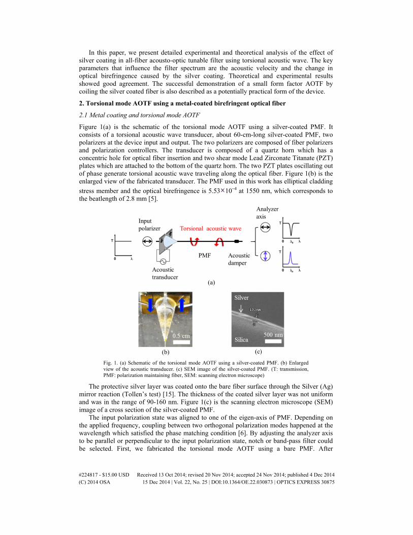
Figure 1(a) is the schematic of the torsional mode AOTF using a silver-coated PMF. It consists of a torsional acoustic wave transducer, about 60-cm-long silver-coated PMF, two polarizers at the device input and output. The two polarizers are composed of fiber polarizers and polarization controllers. The transducer is composed of a quartz horn which has a concentric hole for optical fiber insertion and two shear mode Lead Zirconate Titanate (PZT) plates which are attached to the bottom of the quartz horn. The two PZT plates oscillating out of phase generate torsional acoustic wave traveling along the optical fiber. Figure 1(b) is the enlarged view of the fabricated transducer. The PMF used in this work has elliptical cladding
stress member and the optical birefringence is 5.53 10−4 at 1550 nm, which corresponds to the beatlength of 2.8 mm [5].
Fig. 1. (a) Schematic of the torsional mode AOTF using a silver-coated PMF. (b) Enlarged view of the acoustic transducer. (c) SEM image of the silver-coated PMF. (T: transmission, PMF: polarization maintaining fiber, SEM: scanning electron microscope)
The protective silver layer was coated onto the bare fiber surface through the Silver (Ag) mirror reaction (Tollen’s test) [15]. The thickness of the coated silver layer was not uniform and was in the range of 90-160 nm. Figure 1(c) is the scanning electron microscope (SEM) image of a cross section of the silver-coated PMF.
The input polarization state was aligned to one of the eigen-axis of PMF. Depending on the applied frequency, coupling between two orthogonal polarization modes happened at the wavelength which satisfied the phase matching condition [6]. By adjusting the analyzer axis to be parallel or perpendicular to the input polarization state, notch or band-pass filter could be selected. First, we fabricated the torsional mode AOTF using a bare PMF. After
#224817 - $15.00 USD Received 13 Oct 2014; revised 20 Nov 2014; accepted 24 Nov 2014; published 4 Dec 2014 (C) 2014 OSA 15 Dec 2014 | Vol. 22, No. 25 | DOI:10.1364/OE.22.030873 | OPTICS EXPRESS 30875
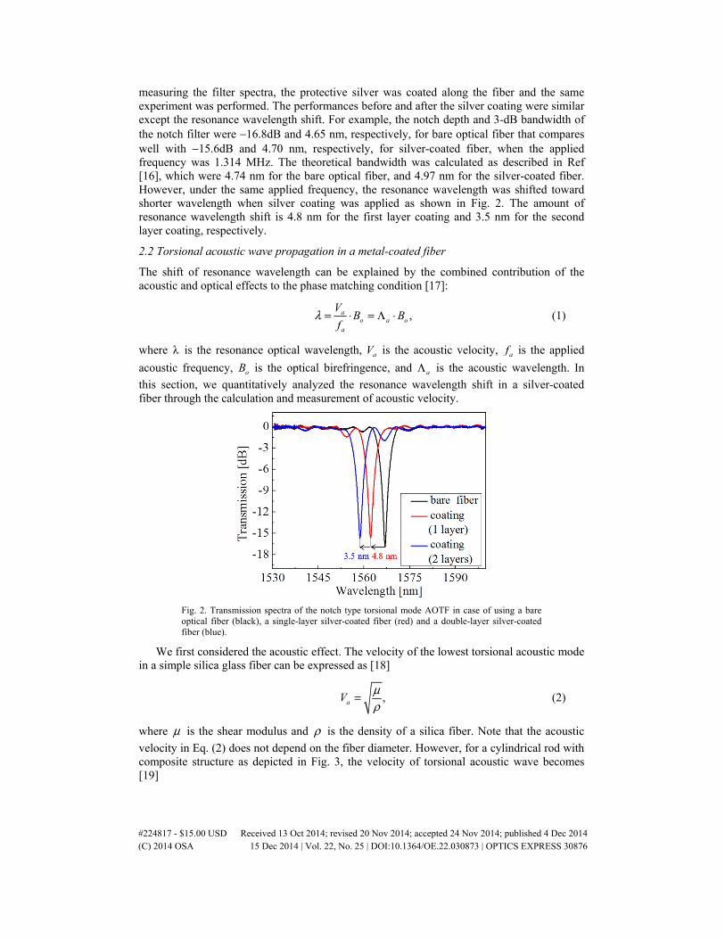
measuring the filter spectra, the protective silver was coated along the fiber and the same experiment was performed. The performances before and after the silver coating were similar except the resonance wavelength shift. For example, the notch depth and 3-dB bandwidth of the notch filter were −16.8dB and 4.65 nm, respectively, for bare optical fiber that compares well with −15.6dB and 4.70 nm, respectively, for silver-coated fiber, when the applied frequency was 1.314 MHz. The theoretical bandwidth was calculated as described in Ref [16], which were 4.74 nm for the bare optical fiber, and 4.97 nm for the silver-coated fiber. However, under the same applied frequency, the resonance wavelength was shifted toward shorter wavelength when silver coating was applied as shown in Fig. 2. The amount of resonance wavelength shift is 4.8 nm for the first layer coating and 3.5 nm for the second layer coating, respectively.
2.2 Torsional acoustic wave propagation in a metal-coated fiber
The shift of resonance wavelength can be explained by the combined contribution of the acoustic and optical effects to the phase matching condition [17]:
,ao a o
a
VB B
fλ = ⋅ = Λ ⋅ (1)
where λ is the resonance optical wavelength, aV is the acoustic velocity, af is the applied
acoustic frequency, oB is the optical birefringence, and aΛ is the acoustic wavelength. In
this section, we quantitatively analyzed the resonance wavelength shift in a silver-coated fiber through the calculation and measurement of acoustic velocity.
Fig. 2. Transmission spectra of the notch type torsional mode AOTF in case of using a bare optical fiber (black), a single-layer silver-coated fiber (red) and a double-layer silver-coated fiber (blue).
We first considered the acoustic effect. The velocity of the lowest torsional acoustic mode in a simple silica glass fiber can be expressed as [18]
,aVμρ
= (2)
where μ is the shear modulus and ρ is the density of a silica fiber. Note that the acoustic
velocity in Eq. (2) does not depend on the fiber diameter. However, for a cylindrical rod with composite structure as depicted in Fig. 3, the velocity of torsional acoustic wave becomes [19]
#224817 - $15.00 USD Received 13 Oct 2014; revised 20 Nov 2014; accepted 24 Nov 2014; published 4 Dec 2014 (C) 2014 OSA 15 Dec 2014 | Vol. 22, No. 25 | DOI:10.1364/OE.22.030873 | OPTICS EXPRESS 30876

14 2
1 24
1 2
( 1), 1 .
( 1)a
hV
R
μ μ ξ ξρ ρ ξ
+ −= = + + −
(3)
Fig. 3. Schematic of a cylindrical structure composed of two different materials used for the analysis of a silver-coated optical fiber.
Table 1. The parameters for the cylindrical rod with composite structure.
Fused silica (R = 62.5μm)
Silver
Shear modulus (GPa) 1μ = 30.93 2μ = 30
Density (kg/m3) 1ρ = 2200 2ρ = 10490
Table 1 shows the parameters for the cylindrical rod with composite structure. Here, 1μ
and 2μ are the shear moduli of the inner and outer layer, respectively, 1ρ and 2ρ are the
densities of the inner and outer layer, respectively, h is the thickness of the outer layer and R is the radius of the inner layer. Equation (3) should be applied to the silver coated fiber because the silica glass and silver have very different acoustic properties. One can see that the torsional wave velocity in the sliver-coated optical fiber decreases as the coating thickness h increases when 1μ > 2μ and 1ρ < 2ρ which are the conditions that apply to this
experiment. This will shift the resonance wavelength toward shorter wavelength based on Eq. (1) although the optical effect should be included that will be discussed later. However, Eq. (3) assumes a perfect coaxial cylindrical structure while the actual silver coating used in our experiments has a thickness variation in the azimuthal and longitudinal dimensions. Therefore, for the calculation of the resonance wavelength shift, an effective coating thickness was estimated from the measurement of acoustic velocity. While a few methods have been reported to measure the longitudinal and the flexural acoustic wave velocities in sensors or waveguide systems [20–22], the direct velocity measurement of torsional acoustic wave in an optical fiber has not been reported, to the best of our knowledge.
2.3 Velocity measurement of torsional acoustic wave in a metal-coated fiber
As shown in Fig. 4(a), pulse-echo method in pitch-catch configuration [20] was used to measure the velocity of torsional acoustic wave. The “pitcher” is the torsional acoustic wave transducer of Fig. 1, and the “catcher” is another transducer setup without function generator (FG) which converts the received torsional acoustic wave and its echoes into electrical signal. The FG generates the tone burst signals of 1 ms period and each burst is composed of 5 cycles of 1.2 MHz sinusoidal tone with 10 Vpp. After propagating along the fiber under test, the transmitted acoustic signal as well as the echo signals are displayed on an oscilloscope via the receiver transducer. Figure 4(b) is the detected waveforms within 1 ms period in a bare optical fiber. The periodic echoes are due to the multiple reflections between the two horns, which show gradual decrease of acoustic intensity due to reflection coefficients and
#224817 - $15.00 USD Received 13 Oct 2014; revised 20 Nov 2014; accepted 24 Nov 2014; published 4 Dec 2014 (C) 2014 OSA 15 Dec 2014 | Vol. 22, No. 25 | DOI:10.1364/OE.22.030873 | OPTICS EXPRESS 30877
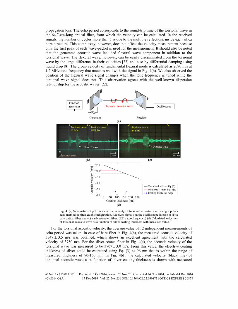
propagation loss. The echo period corresponds to the round-trip time of the torsional wave in the 64.7-cm-long optical fiber, from which the velocity can be calculated. In the received signals, the number of cycles more than 5 is due to the multiple reflections inside each silica horn structure. This complexity, however, does not affect the velocity measurement because only the first peak of each wave-packet is used for the measurement. It should also be noted that the generated acoustic wave included flexural wave component in addition to the torsional wave. The flexural wave, however, can be easily discriminated from the torsional wave by the large difference in their velocities [22] and also by differential damping using liquid drop [8]. The group velocity of fundamental flexural mode is calculated as 2090 m/s at 1.2 MHz tone frequency that matches well with the signal in Fig. 4(b). We also observed the position of the flexural wave signal changes when the tone frequency is tuned while the torsional wave signal does not. This observation agrees with the well-known dispersion relationship for the acoustic waves [22].
Fig. 4. (a) Schematic setup to measure the velocity of torsional acoustic wave using a pulse-echo method in pitch-catch configuration. Received signals on the oscilloscope in case of (b) a bare optical fiber and (c) a silver-coated fiber. (RF: radio frequency) (d) Calculated velocities of torsional acoustic wave as a function of silver coating thickness with measured value.
For the torsional acoustic velocity, the average value of 12 independent measurements of echo period was taken. In case of bare fiber in Fig. 4(b), the measured acoustic velocity of 3747 ± 3.5 m/s was obtained, which shows an excellent agreement with the calculated velocity of 3750 m/s. For the silver-coated fiber in Fig. 4(c), the acoustic velocity of the torsional wave was measured to be 3707 ± 3.0 m/s. From this value, the effective coating thickness of silver could be estimated using Eq. (3) as 96 nm that is within the range of measured thickness of 90-160 nm. In Fig. 4(d), the calculated velocity (black line) of torsional acoustic wave as a function of silver coating thickness is shown with measured
#224817 - $15.00 USD Received 13 Oct 2014; revised 20 Nov 2014; accepted 24 Nov 2014; published 4 Dec 2014 (C) 2014 OSA 15 Dec 2014 | Vol. 22, No. 25 | DOI:10.1364/OE.22.030873 | OPTICS EXPRESS 30878
acoustic velocity (red circle). Red arrow represents the effective coating thickness which corresponds to the measured acoustic velocity in Fig. 4(c). The range of coating thickness (blue arrow) estimated from actual measurement is also shown in the figure.
The resonance optical wavelength shift caused by metal coating can be expressed as
( )1( ) ( ) ,a a
a
V B V Bf
λ λ λΔ = Δ ⋅ + ⋅ Δ (4)
where λΔ is the amount of resonance wavelength shift, af is the applied acoustic frequency,
and aVΔ and BΔ are the amounts of acoustic velocity and optical birefringence changes,
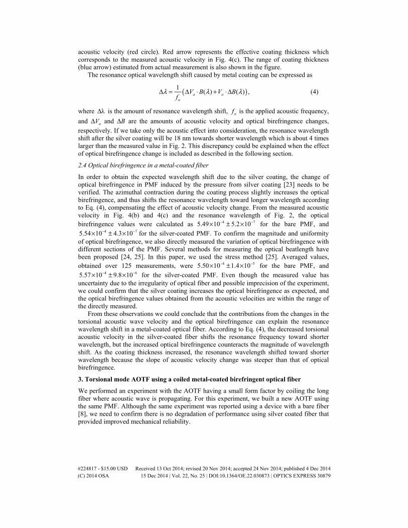
respectively. If we take only the acoustic effect into consideration, the resonance wavelength shift after the silver coating will be 18 nm towards shorter wavelength which is about 4 times larger than the measured value in Fig. 2. This discrepancy could be explained when the effect of optical birefringence change is included as described in the following section.
2.4 Optical birefringence in a metal-coated fiber
In order to obtain the expected wavelength shift due to the silver coating, the change of optical birefringence in PMF induced by the pressure from silver coating [23] needs to be verified. The azimuthal contraction during the coating process slightly increases the optical birefringence, and thus shifts the resonance wavelength toward longer wavelength according to Eq. (4), compensating the effect of acoustic velocity change. From the measured acoustic velocity in Fig. 4(b) and 4(c) and the resonance wavelength of Fig. 2, the optical birefringence values were calculated as 4 75.49 10 5.2 10− −× ± × for the bare PMF, and
4 75.54 10 4.3 10− −× ± × for the silver-coated PMF. To confirm the magnitude and uniformity of optical birefringence, we also directly measured the variation of optical birefringence with different sections of the PMF. Several methods for measuring the optical beatlength have been proposed [24, 25]. In this paper, we used the stress method [25]. Averaged values, obtained over 125 measurements, were 4 55.50 10 1.4 10− −× ± × for the bare PMF, and
4 65.57 10 9.8 10− −× ± × for the silver-coated PMF. Even though the measured value has uncertainty due to the irregularity of optical fiber and possible imprecision of the experiment, we could confirm that the silver coating increases the optical birefringence as expected, and the optical birefringence values obtained from the acoustic velocities are within the range of the directly measured.
From these observations we could conclude that the contributions from the changes in the torsional acoustic wave velocity and the optical birefringence can explain the resonance wavelength shift in a metal-coated optical fiber. According to Eq. (4), the decreased torsional acoustic velocity in the silver-coated fiber shifts the resonance frequency toward shorter wavelength, but the increased optical birefringence counteracts the magnitude of wavelength shift. As the coating thickness increased, the resonance wavelength shifted toward shorter wavelength because the slope of acoustic velocity change was steeper than that of optical birefringence.
3. Torsional mode AOTF using a coiled metal-coated birefringent optical fiber
We performed an experiment with the AOTF having a small form factor by coiling the long fiber where acoustic wave is propagating. For this experiment, we built a new AOTF using the same PMF. Although the same experiment was reported using a device with a bare fiber [8], we need to confirm there is no degradation of performance using silver coated fiber that provided improved mechanical reliability.
#224817 - $15.00 USD Received 13 Oct 2014; revised 20 Nov 2014; accepted 24 Nov 2014; published 4 Dec 2014 (C) 2014 OSA 15 Dec 2014 | Vol. 22, No. 25 | DOI:10.1364/OE.22.030873 | OPTICS EXPRESS 30879
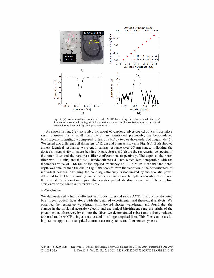
Fig. 5. (a) Volume-reduced torsional mode AOTF by coiling the silver-coated fiber. (b) Resonance wavelength tuning at different coiling diameters. Transmission spectra in case of (c) notch type filter and (d) band-pass type filter.
As shown in Fig. 5(a), we coiled the about 65-cm-long silver-coated optical fiber into a small diameter for a small form factor. As mentioned previously, the bend-induced birefringence is negligible compared to that of PMF by two or three orders of magnitude [7]. We tested two different coil diameters of 12 cm and 6 cm as shown in Fig. 5(b). Both showed almost identical resonance wavelength tuning response over 35 nm range, indicating the device’s insensitivity to macro-bending. Figure 5(c) and 5(d) are the representative spectra of the notch filter and the band-pass filter configuration, respectively. The depth of the notch filter was −11.5dB, and the 3-dB bandwidth was 4.9 nm which was comparable with the theoretical value of 4.66 nm at the applied frequency of 1.322 MHz. Note that the notch depth was smaller than the one in Fig. 2 that comes from the variation in the performances of individual devices. Assuming the coupling efficiency is not limited by the acoustic power delivered to the fiber, a limiting factor for the maximum notch depth is acoustic reflection at the end of the interaction region that creates partial standing wave [26]. The coupling efficiency of the bandpass filter was 92%.
4. Conclusion
We demonstrated a highly efficient and robust torsional mode AOTF using a metal-coated birefringent optical fiber along with the detailed experimental and theoretical analysis. We observed the resonance wavelength shift toward shorter wavelength and found that the change in the torsional acoustic velocity and the optical birefringence are the origin of the phenomenon. Moreover, by coiling the fiber, we demonstrated robust and volume-reduced torsional mode AOTF using a metal-coated birefringent optical fiber. This filter can be useful in practical application to optical communication systems and fiber sensor systems.
#224817 - $15.00 USD Received 13 Oct 2014; revised 20 Nov 2014; accepted 24 Nov 2014; published 4 Dec 2014 (C) 2014 OSA 15 Dec 2014 | Vol. 22, No. 25 | DOI:10.1364/OE.22.030873 | OPTICS EXPRESS 30880

Acknowledgments
This research was supported by Basic Science Research Program through the National Research Foundation of Korea (NRF) funded by the Ministry of Science, ICT & Future Planning (2013R1A1A2064061). The authors thank Dr. Sejeong Kim (KAIST) for the SEM image.
#224817 - $15.00 USD Received 13 Oct 2014; revised 20 Nov 2014; accepted 24 Nov 2014; published 4 Dec 2014 (C) 2014 OSA 15 Dec 2014 | Vol. 22, No. 25 | DOI:10.1364/OE.22.030873 | OPTICS EXPRESS 30881

![REVIEWARTICLE Hang GAO Researchprogressonultra ... · tive photoelastic coefficients, and acousto-optic figures. KDP crystal is the first choice for multi-dimensional acousto-opticaldevice[1,2]andcurrentlytheonlymaterial](https://static.fdocuments.net/doc/165x107/5fcae95a062b7d63f279a725/reviewarticle-hang-gao-researchprogressonultra-tive-photoelastic-coeficients.jpg)