Effect of cutting parameters on chip formation in ...jamme.acmsse.h2.pl/papers_vol50_1/5011.pdf ·...
11
© Copyright by International OCSCO World Press. All rights reserved. 2012 Research paper 7 VOLUME 50 ISSUE 1 January 2012 of Achievements in Materials and Manufacturing Engineering of Achievements in Materials and Manufacturing Engineering Effect of cutting parameters on chip formation in orthogonal cutting S. Ben Salem a , E. Bayraktar b, *, M. Boujelbene a,b , D. Katundi b a 1MA2I Laboratory, National Engineering School of Tunis, Tunisia b Supmeca/LISMMA-Paris, School of Mechanical and Manufacturing Engineering, France * Corresponding e-mail address: [email protected] Received 24.11.2011; published in revised form 01.01.2012 Manufacturing and processing ABSTRACT Purpose: of this paper is to study the chip formation to obtain the optimal cutting conditions and to observe the different chip formation mechanisms. Analysis of machining of a hardened alloy, X160CrMoV12-1 (cold work steel: AISI D2 with a ferritic and cementite matrix and coarse primary carbides), showed that there are relationships between the chip geometry, cutting conditions and the different micrographs under different metallurgical states. Design/methodology/approach: Machining of hardened alloys has some metallurgical and mechanical difficulties even if many successful processes have been increasingly developed. A lot of study has been carried out on this subject, however only with modest progress showing specific results concerning the real efficiency of chip formation. Hence, some crucial questions remain unanswered: the evolution of white layers produced during progressive tool flank wear in dry hard turning and to correlate this with the surface integrity of the machined surface. For the experimental study here, various cutting speeds and feed rates have been applied on the work material. Findings: The “saw-tooth type chips” geometry has been examined and a specific attention was given to the chip samples that were metallographically processed and observed under scanning electronic microscope (SEM) to determine if white layers are present. Research limitations/implications: This research will be followed by a detail modelling and need more experimental results for a given a good prediction of the results occurred on the damage related to the microstructure by using the cutting parameters. Practical implications: A special detail was given to the mechanism of chip formation resulting from hard machining process and behaviour of steel at different metallurgical states on the material during the case of annealing and or the case of quench operations. Originality/value: For the sake of simplicity, ANOVA (Analysis of Variance) was used to determine the influence of cutting parameters. It gives a practical and useful tool for the machining in the industrial operations. Keywords: Damage analyse; Hard machining; Cutting parameters; Chip formation; ANOVA Reference to this paper should be given in the following way: S. Ben Salem, E. Bayraktar, M. Boujelbene, D. Katundi, Effect of cutting parameters on chip formation in orthogonal cutting, Journal of Achievements in Materials and Manufacturing Engineering 50/1 (2012) 7-17.
Transcript of Effect of cutting parameters on chip formation in ...jamme.acmsse.h2.pl/papers_vol50_1/5011.pdf ·...

© Copyright by International OCSCO World Press. All rights reserved. 2012 Research paper 7
VOLUME 50
ISSUE 1
January
2012of Achievements in Materialsand Manufacturing Engineeringof Achievements in Materialsand Manufacturing Engineering
Effect of cutting parameters on chip formation in orthogonal cutting
S. Ben Salem a, E. Bayraktar b,*, M. Boujelbene a,b, D. Katundi ba 1MA2I Laboratory, National Engineering School of Tunis, Tunisiab Supmeca/LISMMA-Paris, School of Mechanical and Manufacturing Engineering, France* Corresponding e-mail address: [email protected]
Received 24.11.2011; published in revised form 01.01.2012
Manufacturing and processing
AbstrActPurpose: of this paper is to study the chip formation to obtain the optimal cutting conditions and to observe the different chip formation mechanisms. Analysis of machining of a hardened alloy, X160CrMoV12-1 (cold work steel: AISI D2 with a ferritic and cementite matrix and coarse primary carbides), showed that there are relationships between the chip geometry, cutting conditions and the different micrographs under different metallurgical states.Design/methodology/approach: Machining of hardened alloys has some metallurgical and mechanical difficulties even if many successful processes have been increasingly developed. A lot of study has been carried out on this subject, however only with modest progress showing specific results concerning the real efficiency of chip formation. Hence, some crucial questions remain unanswered: the evolution of white layers produced during progressive tool flank wear in dry hard turning and to correlate this with the surface integrity of the machined surface. For the experimental study here, various cutting speeds and feed rates have been applied on the work material.Findings: The “saw-tooth type chips” geometry has been examined and a specific attention was given to the chip samples that were metallographically processed and observed under scanning electronic microscope (SEM) to determine if white layers are present.Research limitations/implications: This research will be followed by a detail modelling and need more experimental results for a given a good prediction of the results occurred on the damage related to the microstructure by using the cutting parameters.Practical implications: A special detail was given to the mechanism of chip formation resulting from hard machining process and behaviour of steel at different metallurgical states on the material during the case of annealing and or the case of quench operations.Originality/value: For the sake of simplicity, ANOVA (Analysis of Variance) was used to determine the influence of cutting parameters. It gives a practical and useful tool for the machining in the industrial operations.Keywords: Damage analyse; Hard machining; Cutting parameters; Chip formation; ANOVA
Reference to this paper should be given in the following way: S. Ben Salem, E. Bayraktar, M. Boujelbene, D. Katundi, Effect of cutting parameters on chip formation in orthogonal cutting, Journal of Achievements in Materials and Manufacturing Engineering 50/1 (2012) 7-17.
Research paper8
Journal of Achievements in Materials and Manufacturing Engineering
S. Ben Salem, E. Bayraktar, M. Boujelbene, D. Katundi
Volume 50 Issue 1 January 2012
2.2. Machining test Orthogonal cutting tests and bar turning were conducted on a
Realmeca T400 lathe of the steel at various cutting speeds and various feed rate devoted to hard turning as presented in the Figure 2. The choice of the shape of the test specimen makes it possible to minimize the phenomenon of the vibrations in machining (Figure 2a).
However, we did not carry out a detail study here on the tool wear and only some important damage results were given here on the tool followed by breaking during the hard turning. This case endorses the welding of the chip to the tool tip very easily due to increasing of heat phenomenon on the tool, which likely occurs at the end of the cutting process. The joined chip causes very heavy damage on the all of the edge of the tool during the machining. Moreover, the carbides in the matrix of the materials can create grooves by wear on the tool. During the machining, the cutting forces were measured using a tool dynamometer type (Kastler, 9257A).
Table 2 gives detail on the tests conditions. In fact, the ceramics tools are generally used in the case of the finishing point in hard machining and also for the refractory materials because they are very compatible with these types of materials [6].
3. Mechanism of the chip formation
3.1 Morphology of the chip
As well known, all the materials do not show the same behaviour under the same cutting conditions. That is also true for the same material with various hardness that have undergone to
the different heat treatment [4]. In fact, Machining of X160CrMoV12 steel undergone to the heat treatment (quench) shows that the form and the morphology of chip are completely different from that of obtained when the material has undergone to the annealing treatment [3,4,8] for the range of cutting conditions (i.e. cutting speed, Vc varies from 50 to 250 m/min, and feed rate, f varies from 0.05 to 0.2 mm/rev) as shown in the Figures 3 and 4.
Slip band formation can be easily observed depending on the machining conditions (Figure 3).
The analysis of the chips formation shows that the contact of “tool-chip” in case of increased loading and a heavily deformed zone are formed following the applied load.
When the potential loading achieves a threshold value, a crack initiation appears easily in the zone where a considerable amount of chromium carbide is found in the matrix by forming an angle with the direction of the cutting speed. This crack appears at the point of the tool leading a short relaxation. The crack initiation will produce the slip of the matter where the formation of a segment (slice). This phenomenon is repeated again by giving a new segment. And accordingly, the chip is formed in saw-tooth type since the process is cyclic.
In macroscale however, the chips obtained by hard turning, are relatively in different forms and they can change according to the cutting speed (Figure 4). These forms are developed helicoidally, tangled up either in detached form or in the form of continuous arc in the colour of blue and gray.
Here typical chip morphology was identified to realize the effect of cutting speed, feed rate, and depth of cut, etc. during the orthogonal cutting. However, more detailed research on the chip morphology in hard machining should be carried out to help reveal the segmentation chip formation mechanisms as well as encourage hard machining to be a practical expertise.
Table 2. Test conditions; Observation of the samples
Cutting operations Orthogonal turning Notation
Cutting parameters Cutting speed
Feed rate Depth of cut
Vc = from 50 to 250m/min f = from 0.05 to 0.2mm/rev
ap = 2 mm
Cutting tool Ceramic tool CC 650
Cutting edge angle r = 90°, = 0°, = -6°
Work piece materials X160CrMoV12 Austenitisation at 1030°C, quench in oil
Macro -observation Forces :
Hardness chip
Fa, Ft (N) HRC forms
Micro-observation Microscope Chip geometry
SEM Microstructure Depth of white layer
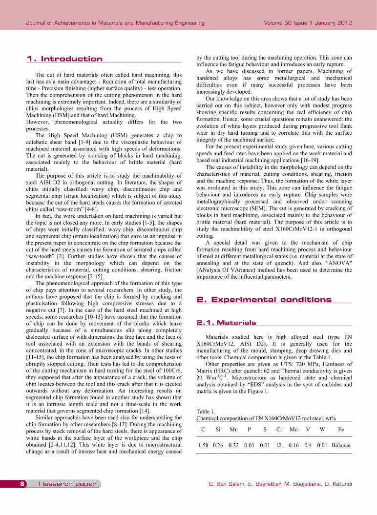
1. Introduction The cut of hard materials often called hard machining, this
last has as a main advantage: - Reduction of total manufacturing time - Precision finishing (higher surface quality) - less operation. Then the comprehension of the cutting phenomenon in the hard machining is extremely important. Indeed, there are a similarity of chips morphologies resulting from the process of High Speed Machining (HSM) and that of hard Machining. However, phenomenological actuality differs for the two processes.
The High Speed Machining (HSM) generates a chip to adiabatic shear band [1-9] due to the viscoplastic behaviour of machined material associated with high speeds of deformations. The cut is generated by cracking of blocks in hard machining, associated mainly to the behaviour of brittle material (hard material).
The purpose of this article is to study the machinability of steel AISI D2 in orthogonal cutting. In literature, the shapes of chips initially classified: wavy chip, discontinuous chip and segmental chip (strain localization) which is subject of this study because the cut of the hard steels causes the formation of serrated chips called “saw-tooth” [4-8].
In fact, the work undertaken on hard machining is varied but the topic is not closed any more. In early studies [1-5], the shapes of chips were initially classified: wavy chip, discontinuous chip and segmental chip (strain localization) that gave us an impulse in the present paper to concentrate on the chip formation because the cut of the hard steels causes the formation of serrated chips called “saw-tooth” [2]. Further studies have shown that the causes of instability in the morphology which can depend on the characteristics of material, cutting conditions, shearing, friction and the machine response [2-15].
The phenomenological approach of the formation of this type of chip pays attention to several researchers. In other study, the authors have proposed that the chip is formed by cracking and plasticisation following high compressive stresses due to a negative cut [7]. In the case of the hard steel machined at high speeds, some researches [10-13] have assumed that the formation of chip can be done by movement of the blocks which leave gradually because of a simultaneous slip along completely dislocated surface of with dimensions the free face and the face of tool associated with an extension with the bands of shearing concentrated, in the zone of microscopic cracks. In other studies [11-15], the chip formation has been analysed by using the tests of abruptly stopped cutting. Their tests has led to the comprehension of the cutting mechanism in hard turning for the steel of 100Cr6, they supposed that after the appearance of a crack, the volume of chip locates between the tool and this crack after that it is ejected outwards without any deformation. An interesting results on segmented chip formation found in another study has shown that it is an intrinsic length scale and not a time-scale in the work material that governs segmented chip formation [14].
Similar approaches have been used also for understanding the chip formation by other researchers [8-12]. During the machining process by stock removal of the hard steels, there is appearance of white bands at the surface layer of the workpiece and the chip obtained [2-4,11,12]. This white layer is due to microstructural change as a result of intense heat and mechanical energy caused
by the cutting tool during the machining operation. This zone can influence the fatigue behaviour and introduces an early rupture.
As we have discussed in former papers, Machining of hardened alloys has some metallurgical and mechanical difficulties even if many successful processes have been increasingly developed.
Our knowledge on this area shows that a lot of study has been carried out on this subject, however only with modest progress showing specific results concerning the real efficiency of chip formation. Hence, some crucial questions remain unanswered: the evolution of white layers produced during progressive tool flank wear in dry hard turning and to correlate this with the surface integrity of the machined surface.
For the present experimental study given here, various cutting speeds and feed rates have been applied on the work material and based real industrial machining applications [16-19].
The causes of instability in the morphology can depend on the characteristics of material, cutting conditions, shearing, friction and the machine response. Thus, the formation of the white layer was evaluated in this study. This zone can influence the fatigue behaviour and introduces an early rupture. Chip samples were metallographically processed and observed under scanning electronic microscope (SEM). The cut is generated by cracking of blocks in hard machining, associated mainly to the behaviour of brittle material (hard material). The purpose of this article is to study the machinability of steel X160CrMoV12-1 in orthogonal cutting.
A special detail was given to the mechanism of chip formation resulting from hard machining process and behaviour of steel at different metallurgical states (i.e. material at the state of annealing and at the state of quench). And also, “ANOVA" (ANalysis Of VAriance) method has been used to determine the importance of the influential parameters.
2. Experimental conditions
2.1. Materials Materials studied here is high alloyed steel (type EN
X160CrMoV12, AISI D2). It is generally used for the manufacturing of the mould, stamping, deep drawing dies and other tools. Chemical composition is given in the Table 1.
Other properties are given as UTS: 720 MPa, Hardness of Matrix (HRC) after quench: 62 and Thermal conductivity is given 20 Wm-1C-1. Microstructure as hardened state and chemical analysis obtained by “EDS” analysis in the spot of carbides and matrix is given in the Figure 1.
Table 1. Chemical composition of EN X160CrMoV12 tool steel, wt%
C Si Mn P S Cr Mo V W Fe
1.58 0.26 0.32 0.01 0.01 12. 0.16 0.4 0.01 Balance
1. Introduction
2. Experimental conditions
2.1. Materials

9
Manufacturing and processing
Effect of cutting parameters on chip formation in orthogonal cutting
2.2. Machining test Orthogonal cutting tests and bar turning were conducted on a
Realmeca T400 lathe of the steel at various cutting speeds and various feed rate devoted to hard turning as presented in the Figure 2. The choice of the shape of the test specimen makes it possible to minimize the phenomenon of the vibrations in machining (Figure 2a).
However, we did not carry out a detail study here on the tool wear and only some important damage results were given here on the tool followed by breaking during the hard turning. This case endorses the welding of the chip to the tool tip very easily due to increasing of heat phenomenon on the tool, which likely occurs at the end of the cutting process. The joined chip causes very heavy damage on the all of the edge of the tool during the machining. Moreover, the carbides in the matrix of the materials can create grooves by wear on the tool. During the machining, the cutting forces were measured using a tool dynamometer type (Kastler, 9257A).
Table 2 gives detail on the tests conditions. In fact, the ceramics tools are generally used in the case of the finishing point in hard machining and also for the refractory materials because they are very compatible with these types of materials [6].
3. Mechanism of the chip formation
3.1 Morphology of the chip
As well known, all the materials do not show the same behaviour under the same cutting conditions. That is also true for the same material with various hardness that have undergone to
the different heat treatment [4]. In fact, Machining of X160CrMoV12 steel undergone to the heat treatment (quench) shows that the form and the morphology of chip are completely different from that of obtained when the material has undergone to the annealing treatment [3,4,8] for the range of cutting conditions (i.e. cutting speed, Vc varies from 50 to 250 m/min, and feed rate, f varies from 0.05 to 0.2 mm/rev) as shown in the Figures 3 and 4.
Slip band formation can be easily observed depending on the machining conditions (Figure 3).
The analysis of the chips formation shows that the contact of “tool-chip” in case of increased loading and a heavily deformed zone are formed following the applied load.
When the potential loading achieves a threshold value, a crack initiation appears easily in the zone where a considerable amount of chromium carbide is found in the matrix by forming an angle with the direction of the cutting speed. This crack appears at the point of the tool leading a short relaxation. The crack initiation will produce the slip of the matter where the formation of a segment (slice). This phenomenon is repeated again by giving a new segment. And accordingly, the chip is formed in saw-tooth type since the process is cyclic.
In macroscale however, the chips obtained by hard turning, are relatively in different forms and they can change according to the cutting speed (Figure 4). These forms are developed helicoidally, tangled up either in detached form or in the form of continuous arc in the colour of blue and gray.
Here typical chip morphology was identified to realize the effect of cutting speed, feed rate, and depth of cut, etc. during the orthogonal cutting. However, more detailed research on the chip morphology in hard machining should be carried out to help reveal the segmentation chip formation mechanisms as well as encourage hard machining to be a practical expertise.
Table 2. Test conditions; Observation of the samples
Cutting operations Orthogonal turning Notation
Cutting parameters Cutting speed
Feed rate Depth of cut
Vc = from 50 to 250m/min f = from 0.05 to 0.2mm/rev
ap = 2 mm
Cutting tool Ceramic tool CC 650
Cutting edge angle r = 90°, = 0°, = -6°
Work piece materials X160CrMoV12 Austenitisation at 1030°C, quench in oil
Macro -observation Forces :
Hardness chip
Fa, Ft (N) HRC forms
Micro-observation Microscope Chip geometry
SEM Microstructure Depth of white layer
3. Mechanism of the chip formation
2.2. Machining test
3.1. Morphology of the chip
1. Introduction The cut of hard materials often called hard machining, this
last has as a main advantage: - Reduction of total manufacturing time - Precision finishing (higher surface quality) - less operation. Then the comprehension of the cutting phenomenon in the hard machining is extremely important. Indeed, there are a similarity of chips morphologies resulting from the process of High Speed Machining (HSM) and that of hard Machining. However, phenomenological actuality differs for the two processes.
The High Speed Machining (HSM) generates a chip to adiabatic shear band [1-9] due to the viscoplastic behaviour of machined material associated with high speeds of deformations. The cut is generated by cracking of blocks in hard machining, associated mainly to the behaviour of brittle material (hard material).
The purpose of this article is to study the machinability of steel AISI D2 in orthogonal cutting. In literature, the shapes of chips initially classified: wavy chip, discontinuous chip and segmental chip (strain localization) which is subject of this study because the cut of the hard steels causes the formation of serrated chips called “saw-tooth” [4-8].
In fact, the work undertaken on hard machining is varied but the topic is not closed any more. In early studies [1-5], the shapes of chips were initially classified: wavy chip, discontinuous chip and segmental chip (strain localization) that gave us an impulse in the present paper to concentrate on the chip formation because the cut of the hard steels causes the formation of serrated chips called “saw-tooth” [2]. Further studies have shown that the causes of instability in the morphology which can depend on the characteristics of material, cutting conditions, shearing, friction and the machine response [2-15].
The phenomenological approach of the formation of this type of chip pays attention to several researchers. In other study, the authors have proposed that the chip is formed by cracking and plasticisation following high compressive stresses due to a negative cut [7]. In the case of the hard steel machined at high speeds, some researches [10-13] have assumed that the formation of chip can be done by movement of the blocks which leave gradually because of a simultaneous slip along completely dislocated surface of with dimensions the free face and the face of tool associated with an extension with the bands of shearing concentrated, in the zone of microscopic cracks. In other studies [11-15], the chip formation has been analysed by using the tests of abruptly stopped cutting. Their tests has led to the comprehension of the cutting mechanism in hard turning for the steel of 100Cr6, they supposed that after the appearance of a crack, the volume of chip locates between the tool and this crack after that it is ejected outwards without any deformation. An interesting results on segmented chip formation found in another study has shown that it is an intrinsic length scale and not a time-scale in the work material that governs segmented chip formation [14].
Similar approaches have been used also for understanding the chip formation by other researchers [8-12]. During the machining process by stock removal of the hard steels, there is appearance of white bands at the surface layer of the workpiece and the chip obtained [2-4,11,12]. This white layer is due to microstructural change as a result of intense heat and mechanical energy caused
by the cutting tool during the machining operation. This zone can influence the fatigue behaviour and introduces an early rupture.
As we have discussed in former papers, Machining of hardened alloys has some metallurgical and mechanical difficulties even if many successful processes have been increasingly developed.
Our knowledge on this area shows that a lot of study has been carried out on this subject, however only with modest progress showing specific results concerning the real efficiency of chip formation. Hence, some crucial questions remain unanswered: the evolution of white layers produced during progressive tool flank wear in dry hard turning and to correlate this with the surface integrity of the machined surface.
For the present experimental study given here, various cutting speeds and feed rates have been applied on the work material and based real industrial machining applications [16-19].
The causes of instability in the morphology can depend on the characteristics of material, cutting conditions, shearing, friction and the machine response. Thus, the formation of the white layer was evaluated in this study. This zone can influence the fatigue behaviour and introduces an early rupture. Chip samples were metallographically processed and observed under scanning electronic microscope (SEM). The cut is generated by cracking of blocks in hard machining, associated mainly to the behaviour of brittle material (hard material). The purpose of this article is to study the machinability of steel X160CrMoV12-1 in orthogonal cutting.
A special detail was given to the mechanism of chip formation resulting from hard machining process and behaviour of steel at different metallurgical states (i.e. material at the state of annealing and at the state of quench). And also, “ANOVA" (ANalysis Of VAriance) method has been used to determine the importance of the influential parameters.
2. Experimental conditions
2.1. Materials Materials studied here is high alloyed steel (type EN
X160CrMoV12, AISI D2). It is generally used for the manufacturing of the mould, stamping, deep drawing dies and other tools. Chemical composition is given in the Table 1.
Other properties are given as UTS: 720 MPa, Hardness of Matrix (HRC) after quench: 62 and Thermal conductivity is given 20 Wm-1C-1. Microstructure as hardened state and chemical analysis obtained by “EDS” analysis in the spot of carbides and matrix is given in the Figure 1.
Table 1. Chemical composition of EN X160CrMoV12 tool steel, wt%
C Si Mn P S Cr Mo V W Fe
1.58 0.26 0.32 0.01 0.01 12. 0.16 0.4 0.01 Balance

Research paper10
Journal of Achievements in Materials and Manufacturing Engineering
S. Ben Salem, E. Bayraktar, M. Boujelbene, D. Katundi
Volume 50 Issue 1 January 2012
Continuous-wavy chip (f = 0.02 mm/rev) Wavy chip (f = 0.04 mm/rev)
Saw-tooth chip (f = 0.1 mm/rev) Saw-tooth chip (f = 0.15 mm/rev)
Detail of the form of Saw-tooth chip for a feed rate of f = 0.15 mm/rev
Fig. 5. Chip morphology at varying feed rate, f for a given cutting speed of Vc = 100 m/min
3.2. Influence of the feed on the form of chip
The analysis of the chips shows that the feed rate by turn influences considerably the morphology of the chips. Certainly, the machining of steel “X160 Cr MoV12” hardened (62 HRC) with small feed rates (f = 0.02 mm/rev) allows obtaining a continuous chip, this chip is due to a quasi-stationary plastic deformations in the zones of shearing (Figure 5).
It should be noted that, with the increase in the feed rate and at a constant cutting speed of Vc = 100 m/min, the chip is
increasingly scalloped. It means that it takes more and more the shape of the saw-tooth chip due to cyclic cracking by creating very intensive shear bands.
3.3. Influence of the cutting speed on the form of chip
With increase of the cutting speed, the shearing bands become more and more intense with a considerable reduction in the width of contact between the segments up to fragment (Figure 6).
Secondary carbide
Primary carbide
Fig. 1. Microstructure as hardened state of AISI D2 & chemical analysis obtained by EDS analysis a) b) c)
Fig. 2. a) Specimen form, (b) orthogonal cutting, and c) the carbides in the matrix of the materials create grooves by wear on the tool a) b)
Slip bands
40µm
Slip bands
40µm
Fig. 3. a) Chip formation at Vc=100 m/min, f =0.05 mm/rev, ap=2mm; b) Chip formation at Vc=250 m/min, f =0.2 mm/rev, ap=2mm
a) b) c)
Fig. 4. Macrographic observation of the chip; ap = 2 mm; f = 0.1mm/rev; (a) Vc = 50 m/min; (b) Vc = 150 m/min; (c) Vc = 250 m/min

11
Manufacturing and processing
Effect of cutting parameters on chip formation in orthogonal cutting
Continuous-wavy chip (f = 0.02 mm/rev) Wavy chip (f = 0.04 mm/rev)
Saw-tooth chip (f = 0.1 mm/rev) Saw-tooth chip (f = 0.15 mm/rev)
Detail of the form of Saw-tooth chip for a feed rate of f = 0.15 mm/rev
Fig. 5. Chip morphology at varying feed rate, f for a given cutting speed of Vc = 100 m/min
3.2. Influence of the feed on the form of chip
The analysis of the chips shows that the feed rate by turn influences considerably the morphology of the chips. Certainly, the machining of steel “X160 Cr MoV12” hardened (62 HRC) with small feed rates (f = 0.02 mm/rev) allows obtaining a continuous chip, this chip is due to a quasi-stationary plastic deformations in the zones of shearing (Figure 5).
It should be noted that, with the increase in the feed rate and at a constant cutting speed of Vc = 100 m/min, the chip is
increasingly scalloped. It means that it takes more and more the shape of the saw-tooth chip due to cyclic cracking by creating very intensive shear bands.
3.3. Influence of the cutting speed on the form of chip
With increase of the cutting speed, the shearing bands become more and more intense with a considerable reduction in the width of contact between the segments up to fragment (Figure 6).
3.2. Influence of the feed on the form of chip
3.3. Influence of the cutting speed on the form of chip
Secondary carbide
Primary carbide
Fig. 1. Microstructure as hardened state of AISI D2 & chemical analysis obtained by EDS analysis a) b) c)
Fig. 2. a) Specimen form, (b) orthogonal cutting, and c) the carbides in the matrix of the materials create grooves by wear on the tool a) b)
Slip bands
40µm
Slip bands
40µm
Fig. 3. a) Chip formation at Vc=100 m/min, f =0.05 mm/rev, ap=2mm; b) Chip formation at Vc=250 m/min, f =0.2 mm/rev, ap=2mm
a) b) c)
Fig. 4. Macrographic observation of the chip; ap = 2 mm; f = 0.1mm/rev; (a) Vc = 50 m/min; (b) Vc = 150 m/min; (c) Vc = 250 m/min

Research paper12
Journal of Achievements in Materials and Manufacturing Engineering
S. Ben Salem, E. Bayraktar, M. Boujelbene, D. Katundi
Volume 50 Issue 1 January 2012
As for white and dark layers, a large number of experimental investigations have been carried out in the literature in order to understand the formation mechanisms and properties of white and dark layers in many material removal processes, such as turning, reaming, grinding and electrical discharge machining [16-20]. Quasi these papers were carried out very similar results the evaluation of white layer. As far as the white layer is concerned, three different theories explaining the mechanism of white layer formation have emerged from the literature: I) rapid heating and quenching, which results in sudden phase transformation, II) severe plastic deformation, which produces a homogenous microstructure with a very fine grain size III) surface reaction with the environment, such as in nitriding processes [20-29].
However, some of the authors have indicated that the dark layer formation seems to be a result of microstructural changes in the heat-affected zone as a consequence of the rapid heating and quenching a)
White layerWhite layer
b)
Fig. 7 (a, b). SEM observation of white layer of a part of the chip obtained from steel X160CrMoV1, (Vc = 110 m/min, f = 0.1 mm/rev, ap = 2 mm)
In fact, this work represents an initial attempt to explain the white layer formation. We confirmed here that very defined and considerable thickness of the white layer occurs during the hard machining.
However, we did not detect here a dark layer formation under the experimental conditions. As formerly indicated, the formation of the white and dark layers depends on not only heat treatment due to the operational parameters (cutting force, cutting speed, etc.) but also the materials parameters and some other important metallurgical aspects, such as the grain size, grain elongation, etc.
5. Analyse of cutting forces
The cutting forces recorded by the dynamometric table shows that the tangential force Ft and the feed force Fa decrease when the cutting speed Vc increases (Figure 9) that is due to mainly to the reduction in friction between “tool & chip”. Here, the cutting force, Ft increases depending on the feed rate for a given cutting speed Vc (Figure 9). And also, the feed force, Fa is relatively weak with regard to the tangential cutting force, Ft.
Cutting forces should be considered as the most important technological parameters in machining processes. Essentially, cutting forces are the absolute conditions to evaluate the chip formation and metallurgical aspects and also formation of the total damage on the tool and work pieces. They influence the deformation of the workpiece machined, its dimensional accuracy and chip formation constancy of the total system. More clearly, the cutting force is one of the principal factors that should be known in the metal cutting operations; indeed, cutting forces are in relation with the mechanical properties of the material in the process of chip formation. Since tangential force is dominant in the orthogonal cutting of the hard materials, a statistical study has been carried out under the experimental conditions of the present paper according to the statistical method called “ANOVA” so that one can know the effect of the cutting parameters on the results obtained here. The tests of machining have been carried out for two factors, cutting speed Vc, and feed rate, f on two levels; Vc = 50 and 250 m/min and f = 0.05 and 0.2 mm/rev.
By keeping constant the depth of cut as ap=2mm, all of the tests have been carried out and each test has been repeated 3 times for using as the mean value (Table 3). The calculation of the average and total effects, the construction of the matrix and calculation of the squares totals, squares errors (SStotal, SSerror) can give us to build ANOVA table with A= f and B = Vc as indicated in Table 4.
Considering the experimental results given in the present work, an interesting work was presented in the literature that their results are agree with those of the present study [17-20]. The specific cutting forces are determined in order to understand the interference of chips that occur during the threading. With the increase in the cumulative radial feed, the corresponding specific
cutting forces become higher. They indicated that the difference in the specific cutting forces results from the alteration of the interference of the flowing chips. The specific cutting forces
decrease in the beginning of the threading and then increases with the cumulative radial feed. The results show that the interference of the chip flow influences the threading force components to a very large extent [17-18].
Carbide
White layer
This is attributed to the phenomenon of localized deformation in the primary shear zone that becomes more important with the increase in the temperature.
The mechanical properties of material thus decrease in the cutting zone by reducing resistance to the plastic deformation and thus cause an abrupt shearing of the chip by creating a plastic instability. It should be noted that for a feed rate of 0.1mm/rev, the appearance frequency of the chips is more often as the cutting speed Vc is higher.
40 µm
(a) Vc = 100 m/min
40 µm
(b) Vc = 200 m/min
40 µm
(c) Vc = 300 m/min
Fig. 6. Evolution of chip morphology with cutting speed Vc, f = 0.1 mm/rev
In fact, this morphology is often observed in the case of the machining of hard steels and of low thermal conductivity. The low thermal conductivity and the rapid dissipation of energy lead to consider the shear zone as an area of adiabatic shear. These chips are formed by a localization of deformation and catastrophic shear, thanks to the increase in hardness and brittleness of material. Thus the mechanism of generation of chip is based on the initiation of a crack followed by a slip.
4. Study of white layer The white layer is the result of the microstructural changement in the martensitic structure. A thicker white layer indicates a severe thermal damage. The formation of this white layer occurs because due the presence of concentrated mechanical and thermal energies localised very fast in a strict zone causing the metallurgical transformation and naturally gives the white area as shown in the SEM picture of Figure 7. White layer is regularly formed in hard machined surfaces when a high cutting speed, a worn tool, or a tool with low thermal conductivity is used during machining. General idea proposed in literature for decreasing the formation of white layer and decrease its thickness is that it should be used appropriate cooling, tool material with high thermal conductivity, and the reductions of feed rate, cutting speed, tool nose radius, tool flank wear, etc. A detail study of the mechanisms of chip formation can lead to the comprehension of cutting phenomenon and the control of the surface integrity of the machined parts. In the present paper, the micrographic analysis of the chips showed that they are generally in the shapes of wavy and saw-tooth types having white layers in variable thickness depending on the cutting speed used by always keeping the same feed rate, f, as indicated in the Figure 8a. However, as the cutting speed increases, the thickness of the white layer increases slightly under the experimental conditions of this study. As known well, this part has undergone a heavily plastic deformation. The formation of the white layer is essentially due to an intensive heat sources (i.e. very high thermal gradient at the beginning) localised in the field of cutting during the hard machining. In literature, Surface cooling rate in hard turning is given at the order of 104-105 °C/s and machined surface encounters an extremely short cycle thermo-mechanical process with very high heating rate > 106 °C/s [8]. Obviously, the quantity of the heat transferred towards the chip is more important than that of the workpiece.
Figure 8b indicates the evolution of the hardness of the chip structure depending on the cutting speed for a given feed rate of f = 0.1 mm/rev. These results are the mean values taken from the five measurements for each cutting speed. According to these results obtained here, it is suggested that there is a nearly total dissolution of carbides due to the high temperature generated by plastic deformation at very high cutting speeds. The more the amount of carbon in the matrix increases, the more the melting point of the steel decreases. Additionally, when the tool leaves after each cutting stage, the material undergoes abnormal cooling conditions through its microstructure. Large amount of austenite cannot find enough time to transform at high cutting speeds and a considerable amount of fresh martensite or remained austenite are found in the structure not only in white layer but also within the microstructure of the chip.
V
V
V V
40 µm
4. study of white layer

13
Manufacturing and processing
Effect of cutting parameters on chip formation in orthogonal cutting
As for white and dark layers, a large number of experimental investigations have been carried out in the literature in order to understand the formation mechanisms and properties of white and dark layers in many material removal processes, such as turning, reaming, grinding and electrical discharge machining [16-20]. Quasi these papers were carried out very similar results the evaluation of white layer. As far as the white layer is concerned, three different theories explaining the mechanism of white layer formation have emerged from the literature: I) rapid heating and quenching, which results in sudden phase transformation, II) severe plastic deformation, which produces a homogenous microstructure with a very fine grain size III) surface reaction with the environment, such as in nitriding processes [20-29].
However, some of the authors have indicated that the dark layer formation seems to be a result of microstructural changes in the heat-affected zone as a consequence of the rapid heating and quenching a)
White layerWhite layer
b)
Fig. 7 (a, b). SEM observation of white layer of a part of the chip obtained from steel X160CrMoV1, (Vc = 110 m/min, f = 0.1 mm/rev, ap = 2 mm)
In fact, this work represents an initial attempt to explain the white layer formation. We confirmed here that very defined and considerable thickness of the white layer occurs during the hard machining.
However, we did not detect here a dark layer formation under the experimental conditions. As formerly indicated, the formation of the white and dark layers depends on not only heat treatment due to the operational parameters (cutting force, cutting speed, etc.) but also the materials parameters and some other important metallurgical aspects, such as the grain size, grain elongation, etc.
5. Analyse of cutting forces
The cutting forces recorded by the dynamometric table shows that the tangential force Ft and the feed force Fa decrease when the cutting speed Vc increases (Figure 9) that is due to mainly to the reduction in friction between “tool & chip”. Here, the cutting force, Ft increases depending on the feed rate for a given cutting speed Vc (Figure 9). And also, the feed force, Fa is relatively weak with regard to the tangential cutting force, Ft.
Cutting forces should be considered as the most important technological parameters in machining processes. Essentially, cutting forces are the absolute conditions to evaluate the chip formation and metallurgical aspects and also formation of the total damage on the tool and work pieces. They influence the deformation of the workpiece machined, its dimensional accuracy and chip formation constancy of the total system. More clearly, the cutting force is one of the principal factors that should be known in the metal cutting operations; indeed, cutting forces are in relation with the mechanical properties of the material in the process of chip formation. Since tangential force is dominant in the orthogonal cutting of the hard materials, a statistical study has been carried out under the experimental conditions of the present paper according to the statistical method called “ANOVA” so that one can know the effect of the cutting parameters on the results obtained here. The tests of machining have been carried out for two factors, cutting speed Vc, and feed rate, f on two levels; Vc = 50 and 250 m/min and f = 0.05 and 0.2 mm/rev.
By keeping constant the depth of cut as ap=2mm, all of the tests have been carried out and each test has been repeated 3 times for using as the mean value (Table 3). The calculation of the average and total effects, the construction of the matrix and calculation of the squares totals, squares errors (SStotal, SSerror) can give us to build ANOVA table with A= f and B = Vc as indicated in Table 4.
Considering the experimental results given in the present work, an interesting work was presented in the literature that their results are agree with those of the present study [17-20]. The specific cutting forces are determined in order to understand the interference of chips that occur during the threading. With the increase in the cumulative radial feed, the corresponding specific
cutting forces become higher. They indicated that the difference in the specific cutting forces results from the alteration of the interference of the flowing chips. The specific cutting forces
decrease in the beginning of the threading and then increases with the cumulative radial feed. The results show that the interference of the chip flow influences the threading force components to a very large extent [17-18].
Carbide
White layer
5. Analyse of cutting forces
This is attributed to the phenomenon of localized deformation in the primary shear zone that becomes more important with the increase in the temperature.
The mechanical properties of material thus decrease in the cutting zone by reducing resistance to the plastic deformation and thus cause an abrupt shearing of the chip by creating a plastic instability. It should be noted that for a feed rate of 0.1mm/rev, the appearance frequency of the chips is more often as the cutting speed Vc is higher.
40 µm
(a) Vc = 100 m/min
40 µm
(b) Vc = 200 m/min
40 µm
(c) Vc = 300 m/min
Fig. 6. Evolution of chip morphology with cutting speed Vc, f = 0.1 mm/rev
In fact, this morphology is often observed in the case of the machining of hard steels and of low thermal conductivity. The low thermal conductivity and the rapid dissipation of energy lead to consider the shear zone as an area of adiabatic shear. These chips are formed by a localization of deformation and catastrophic shear, thanks to the increase in hardness and brittleness of material. Thus the mechanism of generation of chip is based on the initiation of a crack followed by a slip.
4. Study of white layer The white layer is the result of the microstructural changement in the martensitic structure. A thicker white layer indicates a severe thermal damage. The formation of this white layer occurs because due the presence of concentrated mechanical and thermal energies localised very fast in a strict zone causing the metallurgical transformation and naturally gives the white area as shown in the SEM picture of Figure 7. White layer is regularly formed in hard machined surfaces when a high cutting speed, a worn tool, or a tool with low thermal conductivity is used during machining. General idea proposed in literature for decreasing the formation of white layer and decrease its thickness is that it should be used appropriate cooling, tool material with high thermal conductivity, and the reductions of feed rate, cutting speed, tool nose radius, tool flank wear, etc. A detail study of the mechanisms of chip formation can lead to the comprehension of cutting phenomenon and the control of the surface integrity of the machined parts. In the present paper, the micrographic analysis of the chips showed that they are generally in the shapes of wavy and saw-tooth types having white layers in variable thickness depending on the cutting speed used by always keeping the same feed rate, f, as indicated in the Figure 8a. However, as the cutting speed increases, the thickness of the white layer increases slightly under the experimental conditions of this study. As known well, this part has undergone a heavily plastic deformation. The formation of the white layer is essentially due to an intensive heat sources (i.e. very high thermal gradient at the beginning) localised in the field of cutting during the hard machining. In literature, Surface cooling rate in hard turning is given at the order of 104-105 °C/s and machined surface encounters an extremely short cycle thermo-mechanical process with very high heating rate > 106 °C/s [8]. Obviously, the quantity of the heat transferred towards the chip is more important than that of the workpiece.
Figure 8b indicates the evolution of the hardness of the chip structure depending on the cutting speed for a given feed rate of f = 0.1 mm/rev. These results are the mean values taken from the five measurements for each cutting speed. According to these results obtained here, it is suggested that there is a nearly total dissolution of carbides due to the high temperature generated by plastic deformation at very high cutting speeds. The more the amount of carbon in the matrix increases, the more the melting point of the steel decreases. Additionally, when the tool leaves after each cutting stage, the material undergoes abnormal cooling conditions through its microstructure. Large amount of austenite cannot find enough time to transform at high cutting speeds and a considerable amount of fresh martensite or remained austenite are found in the structure not only in white layer but also within the microstructure of the chip.
V
V
V V
40 µm

Research paper14
Journal of Achievements in Materials and Manufacturing Engineering
S. Ben Salem, E. Bayraktar, M. Boujelbene, D. Katundi
Volume 50 Issue 1 January 2012
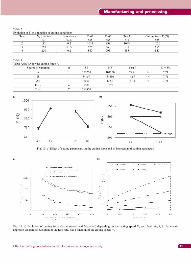
Table 3. Evolution of Ft as a function of cutting conditions
Test Vc (m/min) f (mm/rev) Test1 Test2 Test3 Cutting force Ft (N) 1 50 0.05 835 865 775 825 2 50 0.2 1014 998 1048 1020 3 250 0.05 675 660 630 655 4 250 0.2 840 795 885 840
Table 4. Table ANOVA for the cutting force Ft
Source of variation df SS MS Test F F = 5% A 1 101250 101250 79.41 > 7.71 B 1 54450 54450 42.7 > 7.71
AB 1 6050 6050 4.74 < 7.71 Error 4 5100 1275 Total 7 166850
a) b)
Fig. 10. a) Effect of cutting parameters on the cutting force and b) Interaction of cutting parameters a) b)
Fig. 11. a) Evolution of cutting force (Experimental and Modelled) depending on the cutting speed Vc and feed rate, f, b) Parametric approach diagram of evolution of the feed rate, f as a function of the cutting speed, Vc
a)
0
2
4
6
8
10
0 50 100 150 200 250 300
TWL
(µm
)
Cutting Speed, Vc(m/min)
Hardness of matrix (HRC)=62
AISI D2
b)
500
700
900
1100
0 50 100 150 200 250 300
Chi
p H
ardn
ess (
HV
0.05
)
Cutting Speed, Vc(m/min)
Hardness of matrix
AISI D2
Fig. 8 a) Evolution of white layer “TWL” and (b) the hardness of the chip structure depending on the cutting speed for a given feed rate of f = 0.1 mm/rev (Hardness of matrix HRC:62)
0
200
400
600
800
1000
1200
0 50 100 150 200 250 300
Cut
ting f
orce
Ft (
N)
Cutting speed Vc (m/min)
Ft for f = 0.05mm/revFt for f = 0.2 mm/rev
Fa for f = 0.2 mm/rev
Fig. 9. Evolution of cutting force depending on the cutting speed Vc and feed rate f
Table ANOVA and the test of Fisher show that on a significant level of 5%, the calculated value, Ftcalculated, for A, B are higher than the theoretical value, Fttheoretical.
However, for AB, the calculated value, FtAB-calculated, is lower than the theoretical, FtAB-theoretical. It can be concluded that the cutting speed and the feed rate influence considerably the cutting force, but their interaction does not have so much effect on the cutting force. For the parameter A, Ftest is higher than that of B, and is very high regarding to AB, from where A is more important than B.
The effects and the interaction of the cutting conditions on the cutting force have been presented graphically in the Figure 10. One can be seen that cutting force is compulsory to deform the material plastically though there is a dependency on certain factors. As we mentioned in the former section, the cutting forces are very sensitive to chemical composition, hardness, and microstructure, type of cutting tools used, machine stability, heat generation and operating parameters. [30-31].
Determination of a mathematical model for a tangential force has been made by the method of experimental design. A general equation of this model is given by:
...2110 iiiiiii XbXXbXbbY (1)
where, the values of Xi are calculated by logarithmic transformation curve of the values of the selected factors (Vc, f) according to the equation (2), with bi coefficients of this equation.
xxxX i
i0 (2)
with:
2min
0Maxx (3)
2minMaxx (4)
8175.36583.1 11 xx (5)
8614.52427.1 22 xx (6)
After all of the required calculations, a simple mathematical
model of tangential force, Ft has been proposed here as a function of the cutting speed and feed (equation (7)).
-0.14185.0 Vc42.2428 fFt (7)
The validation of the mathematical model given by equation
(7) is shown in Figure 11 a. According to the model (7), a parametric approach diagram (feed rate/cutting speed) (Figure 11 b) can be plotted which would be an indicative choice of the machining parameters in hard turning.
Indeed, this parametric diagram allows us to know the value of the feed by turn for a given cutting speed and a given the cutting force; by fixing two parameters and to provide for the point on the curve to choose the third one. This parametric approach diagram will be useful for the manufacturers working on the steel X160 CrMoV12 as received or quenched conditions.
15
Manufacturing and processing
Effect of cutting parameters on chip formation in orthogonal cutting
Table 3. Evolution of Ft as a function of cutting conditions
Test Vc (m/min) f (mm/rev) Test1 Test2 Test3 Cutting force Ft (N) 1 50 0.05 835 865 775 825 2 50 0.2 1014 998 1048 1020 3 250 0.05 675 660 630 655 4 250 0.2 840 795 885 840
Table 4. Table ANOVA for the cutting force Ft
Source of variation df SS MS Test F F = 5% A 1 101250 101250 79.41 > 7.71 B 1 54450 54450 42.7 > 7.71
AB 1 6050 6050 4.74 < 7.71 Error 4 5100 1275 Total 7 166850
a) b)
Fig. 10. a) Effect of cutting parameters on the cutting force and b) Interaction of cutting parameters a) b)
Fig. 11. a) Evolution of cutting force (Experimental and Modelled) depending on the cutting speed Vc and feed rate, f, b) Parametric approach diagram of evolution of the feed rate, f as a function of the cutting speed, Vc
a)
0
2
4
6
8
10
0 50 100 150 200 250 300
TWL
(µm
)
Cutting Speed, Vc(m/min)
Hardness of matrix (HRC)=62
AISI D2
b)
500
700
900
1100
0 50 100 150 200 250 300
Chi
p H
ardn
ess (
HV
0.05
)
Cutting Speed, Vc(m/min)
Hardness of matrix
AISI D2
Fig. 8 a) Evolution of white layer “TWL” and (b) the hardness of the chip structure depending on the cutting speed for a given feed rate of f = 0.1 mm/rev (Hardness of matrix HRC:62)
0
200
400
600
800
1000
1200
0 50 100 150 200 250 300
Cut
ting f
orce
Ft (
N)
Cutting speed Vc (m/min)
Ft for f = 0.05mm/revFt for f = 0.2 mm/rev
Fa for f = 0.2 mm/rev
Fig. 9. Evolution of cutting force depending on the cutting speed Vc and feed rate f
Table ANOVA and the test of Fisher show that on a significant level of 5%, the calculated value, Ftcalculated, for A, B are higher than the theoretical value, Fttheoretical.
However, for AB, the calculated value, FtAB-calculated, is lower than the theoretical, FtAB-theoretical. It can be concluded that the cutting speed and the feed rate influence considerably the cutting force, but their interaction does not have so much effect on the cutting force. For the parameter A, Ftest is higher than that of B, and is very high regarding to AB, from where A is more important than B.
The effects and the interaction of the cutting conditions on the cutting force have been presented graphically in the Figure 10. One can be seen that cutting force is compulsory to deform the material plastically though there is a dependency on certain factors. As we mentioned in the former section, the cutting forces are very sensitive to chemical composition, hardness, and microstructure, type of cutting tools used, machine stability, heat generation and operating parameters. [30-31].
Determination of a mathematical model for a tangential force has been made by the method of experimental design. A general equation of this model is given by:
...2110 iiiiiii XbXXbXbbY (1)
where, the values of Xi are calculated by logarithmic transformation curve of the values of the selected factors (Vc, f) according to the equation (2), with bi coefficients of this equation.
xxxX i
i0 (2)
with:
2min
0Maxx (3)
2minMaxx (4)
8175.36583.1 11 xx (5)
8614.52427.1 22 xx (6)
After all of the required calculations, a simple mathematical
model of tangential force, Ft has been proposed here as a function of the cutting speed and feed (equation (7)).
-0.14185.0 Vc42.2428 fFt (7)
The validation of the mathematical model given by equation
(7) is shown in Figure 11 a. According to the model (7), a parametric approach diagram (feed rate/cutting speed) (Figure 11 b) can be plotted which would be an indicative choice of the machining parameters in hard turning.
Indeed, this parametric diagram allows us to know the value of the feed by turn for a given cutting speed and a given the cutting force; by fixing two parameters and to provide for the point on the curve to choose the third one. This parametric approach diagram will be useful for the manufacturers working on the steel X160 CrMoV12 as received or quenched conditions.

Research paper16
Journal of Achievements in Materials and Manufacturing Engineering
S. Ben Salem, E. Bayraktar, M. Boujelbene, D. Katundi
Volume 50 Issue 1 January 2012
[15] G. Sutter, Chip geometries during high-speed machining for orthogonal cutting conditions, International Journal of Machines Tools and Manufacture 45 (2005) 719-726.
[16] M-B. Mhamdi, M. Boujelbene, S. Ben Salem, E. Bayraktar, D. Katundi, Study of chip formation in orthogonal cutting: case of hard machining, Proceedings in CIRP 2nd International Conference Processing in Machine Interactions, Vancouver, 2010, 1-10.
[17] I. Al-Zkeri, J. Rech, T. Altan, H. Hamdi, F. Valiorgue, Optimization of the cutting edge geometry of coated carbide tools in dry turning of steels using a finite element analysis, Machining Science and Technology, An International Journal 13/1 (2009) 36-51.
[18] F. Kafkas, An experimental study on cutting forces in the threading and the side cut turning with coated and uncoated grades, ASME, Journal of Manufacturing Science Engineering 132/4 (2010) 7-14.
[19] M-B. Mhamdi, K. Dhurata, S. Ben salem, M. Boujelbène, E. Bayraktar, Effect of cutting parameters on the chip formation and damage in orthogonal cutting, Hard machining, Journal of Materials, Physics and Applications 2/1315 (2011) 1101-1107.
[20] J.Q. Xie,, A.E. Bayoumi, H.M. Zbib, A study on shear banding in chip formation of orthogonal machining, International Journal of Machine Tools and Manufacture 36/7 (1996) 835-847
[21] D. Umbrello, A.D. Jayal, S. Caruso, O.W. Dillon, I.S. Jawahir, Modelling of white and dark layer formation in hard machining of AISI 52100 Bearing Steel, International Journal of Machining Science and Technology 14/1 (2010) 128-147
[22] Y.B. Guo, J. Sahni, A comparative study of hard turned and cylindrically ground white layers, International Journal of Machine Tools and Manufacture 44/2 (2004) 135-145.
[23] A.W. Warren, Y.B. Guo, M.L. Weaver, The influence of machining induced residual stress and phase transformation on the measurement of subsurface mechanical behaviour using nano indentation, Surface and Coatings Technology 200/11 (2006) 3459-3467
[24] S. Ekinovic, S. Doninsek, I.S. Jawahir, Some observations of the chip formation process and the white layer formation in high speed milling of hardened steel, Machining Science And Technology 8/2 (2004) 327-340.
[25] J. Barry, G. Byrne, TEM study on the surface white layer in two turned hardened steels, Materials Science Engineering A 325/1-2 (2002) 356-364.
[26] Y.K. Chou, C.J. Evans, White layers and thermal modeling of hard turned surfaces, International Journal of Machine Tools and Manufacture 39/12 (1999) 1863.1881.
[27] N.S. Akcan, S. Shah, S.P. Moylan, P.N. Chhabra, S. Chandrasekar, T.N. Farris, Characteristics of white layers formed in steels by machining, Proceedings of the ASME Manufacturing Engineering Division 10 (1999) 789-795.
[28] T.I. Al-Wardany, H.A. Kishawy, M.A. Elbestawi, Surface integrity of die material in high speed hard machining, part 1: micrographical analysis, Journal of Manufacturing Science and Engineering 122/4 (2000) 620-631.
[29] K. Arimoto, G. Li, A. Arvind, W.T. Wu, The modeling of heat treating processes, Proceedings of the ASM 18th Heat Treating Conference, Chicago, 1998.
[30] I. Korkut, M. Kasap, I. Ciftci, U. Sekar, Determination of optimum cutting parameters during machining of AISI 303 austenitic stainless steel, Materials and Design 25 (2004) 303-305.
[31] S. Thamizhmanii, S. Hasan, Relationship between flank wear and cutting force on the machining of hard martensitic stainless steel by super hard tools, Proceedings of the 3rd World Congress on Engineering WCE’2010, London, 2010.
6. Conclusions
The cutting parameters influence the morphology of chip. This chip takes a form of saw tooth in case of hardened state during the hard machining of the AISI D2 steel. Observations of the microstructure reveal that the process of the chip formation gives a continuous form (shearing) in case of annealing and it occurs by crack propagation in case of quenched structure. Thus, the type and the shape of chip depend directly on the physical and mechanical properties of machined material.. White layer is very brittle: cracks can easily nucleate and propagate within. At high cutting speeds, a considerable amount of fresh martensite are found within the microstructure of the chip that results in lower micro hardness values.
As the cutting speed increases, the chips become relatively ductile. Thus, more the cutting speed increases more the chips are segmented microscopically. However, in a macroscopic state, the chips are increasingly in continuous form; this is probably, due to their ductility, and less effect of edge is observed. We have remarkably noticed that at a cutting speed of 50 m/min, there is a part of chip which is continuous, and the other part has relatively different forms.
The method ANOVA permitted us to conclude that the cutting speed and the feed influence significantly the cutting force, whereas, their interactions do not influence this, Ft effort significantly. For the same cutting speed, Vc, the cutting pressure increases considerably when the removal rate of chips increases.
The cutting force necessary to machining is decreased when machining is carried out with a higher cutting speed. This paper proposes some ideas for mathematical models for the cutting force and facilitates the choice of the cutting conditions in case of machining of the tool steel.
All the heat sources produce maximum temperature at the chip-tool interface which substantially influences the chip formation mode, cutting forces and tool life. The heat generated was carried away by the chips rather than maintenance by work pieces. Heat was kept by the tool tip. Increase in the feed rate increases the cutting force. The removal of material take place in a short time for a given length required high cutting forces. The removal of material increased the plastic deformation and also generated more heat generation.
In summary, some useful results was obtained in the present work, but more experiments are needed in order to develop the metallurgical aspects as a results understand the influence of various process parameters on surface and subsurface microstructural changes by using the detail operational parameters.
As mentioned in the present work, other important metallurgical aspects, such as the grain size, grain elongation, etc., should be considered. Moreover, the main reason of the thermal effect under the worn tool condition should be studied for higher regularity segmentation as observed, primary to continuous-like chips. The chip segmentation mechanism needs clear identification since the effect of cutting conditions on machining process information depends on the chip segmentation mechanism. The shear band spacing model should be improved such as considering the work hardening effect to increase its predictive qualifications.
Acknowledgement
The authors would like to thank “LISMMA research foundation” for the going-on research project and also grants for two invited researchers from Tunis for leaving in LISMMA-Paris.
References [1] C. Hortig, B. Svendsen, Simulation of chip formation during
high-speed cutting, Journal of Materials Processing Technology 186 (2007) 66-77.
[2] M. M’hamdi, M. Boujelbene, D., Katundi, E. Bayraktar, Proceedings in CIRP Int. Conference, Processing in Machine Interactions edited by Y. Altintas et al., Vancouver, Canada, 2010, 1-10.
[3] Y.K. Chou, H. Song, Tool nose radius effects on finish hard turning, Journal of Materials Processing Technology 148/2 (2004) 259-268.
[4] Y.K. Chou, Ch.J. Evans, White layers and thermal modeling of hard turned surfaces, International Journal of Machine Tools and Manufacture 39/12 (1999) 1863-1881.
[5] R. Komanduri, R.H. Brown, The mechanics of chip segmentation in machining, Journal of Engineering for Industry 103 (1981) 33-51.
[6] R. Komanduri, T. Schroeder, B.F. VonTurkovitch, O.G. Flom, On the catastrophic shear instability in high speed machining of an AISI 4340 steel, Trans. ASME, Journal of Engineering for Industry 104 (1982) 121-131.
[7] W. Konig, Machining hard materials with geometrically defined cutting edges - Filed of applications and limitations, Annals of CIRP 39/1 (1990) 413-425.
[8] Y. Matsumoto, M.M. Barash, C.R. Liu, Cutting mechanism during machining of hardened steel, Materials Science and Technology 13 (1987) 229-305.
[9] A. Molinari, C. Musquar, G. Sutter, Adiabatic shear banding in high speed machining of Ti-6Al-4V: experiments and modeling"; International journal of Plasticity 18 (2002) 443-459.
[10] K. Nakayama, The formation of saw-toothed chip in metal cutting, Proceedings of the International Conference on Production Engineering, Tokyo 1 (1974) 572-577.
[11] M. Bakkal, A.J. Shih, R.O. Scattergood, Chip formation, cutting forces, and tool wear in turning of Zr-based bulk metallic glass, International Journal of Machine Tools and Manufacture 44 (2004) 915-925.
[12] G. Poulachon, A. Albert, M. Schluraff, I.S. Jawahir, An experimental investigation of work material microstructure effects on white layer formation in PCBN hard turning, International Journal of Machine Tools and Manufacture 45 (2005) 211-218.
[13] M. Shaw, The mechanism of chip formation with hard turning steel, Annals of the CIRP 39/1 (1998) 77-82.
[14] R. Kountanyaa, I. Al-Zkeri, T. Altan, Effect of tool edge geometry and cutting conditions on experimental and simulated chip morphology in orthogonal hard turning of 100Cr6 steel, Journal of Materials Processing Technology 209 (2009) 5068-5076.
6. conclusions
references
Acknowledgements

17READING DIRECT: www.journalamme.org
Manufacturing and processing
[15] G. Sutter, Chip geometries during high-speed machining for orthogonal cutting conditions, International Journal of Machines Tools and Manufacture 45 (2005) 719-726.
[16] M-B. Mhamdi, M. Boujelbene, S. Ben Salem, E. Bayraktar, D. Katundi, Study of chip formation in orthogonal cutting: case of hard machining, Proceedings in CIRP 2nd International Conference Processing in Machine Interactions, Vancouver, 2010, 1-10.
[17] I. Al-Zkeri, J. Rech, T. Altan, H. Hamdi, F. Valiorgue, Optimization of the cutting edge geometry of coated carbide tools in dry turning of steels using a finite element analysis, Machining Science and Technology, An International Journal 13/1 (2009) 36-51.
[18] F. Kafkas, An experimental study on cutting forces in the threading and the side cut turning with coated and uncoated grades, ASME, Journal of Manufacturing Science Engineering 132/4 (2010) 7-14.
[19] M-B. Mhamdi, K. Dhurata, S. Ben salem, M. Boujelbène, E. Bayraktar, Effect of cutting parameters on the chip formation and damage in orthogonal cutting, Hard machining, Journal of Materials, Physics and Applications 2/1315 (2011) 1101-1107.
[20] J.Q. Xie,, A.E. Bayoumi, H.M. Zbib, A study on shear banding in chip formation of orthogonal machining, International Journal of Machine Tools and Manufacture 36/7 (1996) 835-847
[21] D. Umbrello, A.D. Jayal, S. Caruso, O.W. Dillon, I.S. Jawahir, Modelling of white and dark layer formation in hard machining of AISI 52100 Bearing Steel, International Journal of Machining Science and Technology 14/1 (2010) 128-147
[22] Y.B. Guo, J. Sahni, A comparative study of hard turned and cylindrically ground white layers, International Journal of Machine Tools and Manufacture 44/2 (2004) 135-145.
[23] A.W. Warren, Y.B. Guo, M.L. Weaver, The influence of machining induced residual stress and phase transformation on the measurement of subsurface mechanical behaviour using nano indentation, Surface and Coatings Technology 200/11 (2006) 3459-3467
[24] S. Ekinovic, S. Doninsek, I.S. Jawahir, Some observations of the chip formation process and the white layer formation in high speed milling of hardened steel, Machining Science And Technology 8/2 (2004) 327-340.
[25] J. Barry, G. Byrne, TEM study on the surface white layer in two turned hardened steels, Materials Science Engineering A 325/1-2 (2002) 356-364.
[26] Y.K. Chou, C.J. Evans, White layers and thermal modeling of hard turned surfaces, International Journal of Machine Tools and Manufacture 39/12 (1999) 1863.1881.
[27] N.S. Akcan, S. Shah, S.P. Moylan, P.N. Chhabra, S. Chandrasekar, T.N. Farris, Characteristics of white layers formed in steels by machining, Proceedings of the ASME Manufacturing Engineering Division 10 (1999) 789-795.
[28] T.I. Al-Wardany, H.A. Kishawy, M.A. Elbestawi, Surface integrity of die material in high speed hard machining, part 1: micrographical analysis, Journal of Manufacturing Science and Engineering 122/4 (2000) 620-631.
[29] K. Arimoto, G. Li, A. Arvind, W.T. Wu, The modeling of heat treating processes, Proceedings of the ASM 18th Heat Treating Conference, Chicago, 1998.
[30] I. Korkut, M. Kasap, I. Ciftci, U. Sekar, Determination of optimum cutting parameters during machining of AISI 303 austenitic stainless steel, Materials and Design 25 (2004) 303-305.
[31] S. Thamizhmanii, S. Hasan, Relationship between flank wear and cutting force on the machining of hard martensitic stainless steel by super hard tools, Proceedings of the 3rd World Congress on Engineering WCE’2010, London, 2010.
6. Conclusions
The cutting parameters influence the morphology of chip. This chip takes a form of saw tooth in case of hardened state during the hard machining of the AISI D2 steel. Observations of the microstructure reveal that the process of the chip formation gives a continuous form (shearing) in case of annealing and it occurs by crack propagation in case of quenched structure. Thus, the type and the shape of chip depend directly on the physical and mechanical properties of machined material.. White layer is very brittle: cracks can easily nucleate and propagate within. At high cutting speeds, a considerable amount of fresh martensite are found within the microstructure of the chip that results in lower micro hardness values.
As the cutting speed increases, the chips become relatively ductile. Thus, more the cutting speed increases more the chips are segmented microscopically. However, in a macroscopic state, the chips are increasingly in continuous form; this is probably, due to their ductility, and less effect of edge is observed. We have remarkably noticed that at a cutting speed of 50 m/min, there is a part of chip which is continuous, and the other part has relatively different forms.
The method ANOVA permitted us to conclude that the cutting speed and the feed influence significantly the cutting force, whereas, their interactions do not influence this, Ft effort significantly. For the same cutting speed, Vc, the cutting pressure increases considerably when the removal rate of chips increases.
The cutting force necessary to machining is decreased when machining is carried out with a higher cutting speed. This paper proposes some ideas for mathematical models for the cutting force and facilitates the choice of the cutting conditions in case of machining of the tool steel.
All the heat sources produce maximum temperature at the chip-tool interface which substantially influences the chip formation mode, cutting forces and tool life. The heat generated was carried away by the chips rather than maintenance by work pieces. Heat was kept by the tool tip. Increase in the feed rate increases the cutting force. The removal of material take place in a short time for a given length required high cutting forces. The removal of material increased the plastic deformation and also generated more heat generation.
In summary, some useful results was obtained in the present work, but more experiments are needed in order to develop the metallurgical aspects as a results understand the influence of various process parameters on surface and subsurface microstructural changes by using the detail operational parameters.
As mentioned in the present work, other important metallurgical aspects, such as the grain size, grain elongation, etc., should be considered. Moreover, the main reason of the thermal effect under the worn tool condition should be studied for higher regularity segmentation as observed, primary to continuous-like chips. The chip segmentation mechanism needs clear identification since the effect of cutting conditions on machining process information depends on the chip segmentation mechanism. The shear band spacing model should be improved such as considering the work hardening effect to increase its predictive qualifications.
Acknowledgement
The authors would like to thank “LISMMA research foundation” for the going-on research project and also grants for two invited researchers from Tunis for leaving in LISMMA-Paris.
References [1] C. Hortig, B. Svendsen, Simulation of chip formation during
high-speed cutting, Journal of Materials Processing Technology 186 (2007) 66-77.
[2] M. M’hamdi, M. Boujelbene, D., Katundi, E. Bayraktar, Proceedings in CIRP Int. Conference, Processing in Machine Interactions edited by Y. Altintas et al., Vancouver, Canada, 2010, 1-10.
[3] Y.K. Chou, H. Song, Tool nose radius effects on finish hard turning, Journal of Materials Processing Technology 148/2 (2004) 259-268.
[4] Y.K. Chou, Ch.J. Evans, White layers and thermal modeling of hard turned surfaces, International Journal of Machine Tools and Manufacture 39/12 (1999) 1863-1881.
[5] R. Komanduri, R.H. Brown, The mechanics of chip segmentation in machining, Journal of Engineering for Industry 103 (1981) 33-51.
[6] R. Komanduri, T. Schroeder, B.F. VonTurkovitch, O.G. Flom, On the catastrophic shear instability in high speed machining of an AISI 4340 steel, Trans. ASME, Journal of Engineering for Industry 104 (1982) 121-131.
[7] W. Konig, Machining hard materials with geometrically defined cutting edges - Filed of applications and limitations, Annals of CIRP 39/1 (1990) 413-425.
[8] Y. Matsumoto, M.M. Barash, C.R. Liu, Cutting mechanism during machining of hardened steel, Materials Science and Technology 13 (1987) 229-305.
[9] A. Molinari, C. Musquar, G. Sutter, Adiabatic shear banding in high speed machining of Ti-6Al-4V: experiments and modeling"; International journal of Plasticity 18 (2002) 443-459.
[10] K. Nakayama, The formation of saw-toothed chip in metal cutting, Proceedings of the International Conference on Production Engineering, Tokyo 1 (1974) 572-577.
[11] M. Bakkal, A.J. Shih, R.O. Scattergood, Chip formation, cutting forces, and tool wear in turning of Zr-based bulk metallic glass, International Journal of Machine Tools and Manufacture 44 (2004) 915-925.
[12] G. Poulachon, A. Albert, M. Schluraff, I.S. Jawahir, An experimental investigation of work material microstructure effects on white layer formation in PCBN hard turning, International Journal of Machine Tools and Manufacture 45 (2005) 211-218.
[13] M. Shaw, The mechanism of chip formation with hard turning steel, Annals of the CIRP 39/1 (1998) 77-82.
[14] R. Kountanyaa, I. Al-Zkeri, T. Altan, Effect of tool edge geometry and cutting conditions on experimental and simulated chip morphology in orthogonal hard turning of 100Cr6 steel, Journal of Materials Processing Technology 209 (2009) 5068-5076.