EE2003 Circuit Theory - Tom Reboldtomrebold.com/engr12/Spring15/week7/Lec7.pdf · 150 t 2.5 10...
87
1 ENGR12 Circuit Theory Chapter 6 Capacitors and Inductors
Transcript of EE2003 Circuit Theory - Tom Reboldtomrebold.com/engr12/Spring15/week7/Lec7.pdf · 150 t 2.5 10...

1
ENGR12 Circuit Theory
Chapter 6
Capacitors and Inductors

2
Capacitors and Inductors Chapter 6
6.1 Capacitors
6.2 Series and Parallel Capacitors
6.3 Inductors
6.4 Series and Parallel Inductors

The Capacitor
Capacitors are one of the fundamental passive
components. In its most basic form, it is composed
of two plates separated by a dielectric.
The ability to store charge is the definition of
capacitance.
Dielectric Conductors
Capacitance The Capacitor
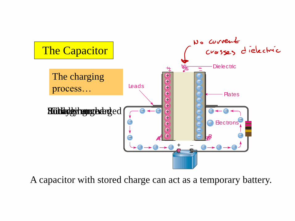
The Capacitor
Dielectric
Plates
Leads
Electrons
BA
+
+
+
+
+
+
+
+
Initially uncharged
+
BA
+
+
+
+
+
+
+
Charging
+
BA
VS
+
+
+++++++++
Fully charged
BA
VS
+
+
+++++++++
Source removed
The charging
process…
A capacitor with stored charge can act as a temporary battery.

Capacitance is the ratio of charge to voltage
QC
V
Rearranging, the amount of charge on a
capacitor is determined by the size of the
capacitor (C) and the voltage (V).
Q CV
If a 22 mF capacitor is connected to
a 10 V source, the charge is 220 mC
Capacitance The Capacitor
Capacitance
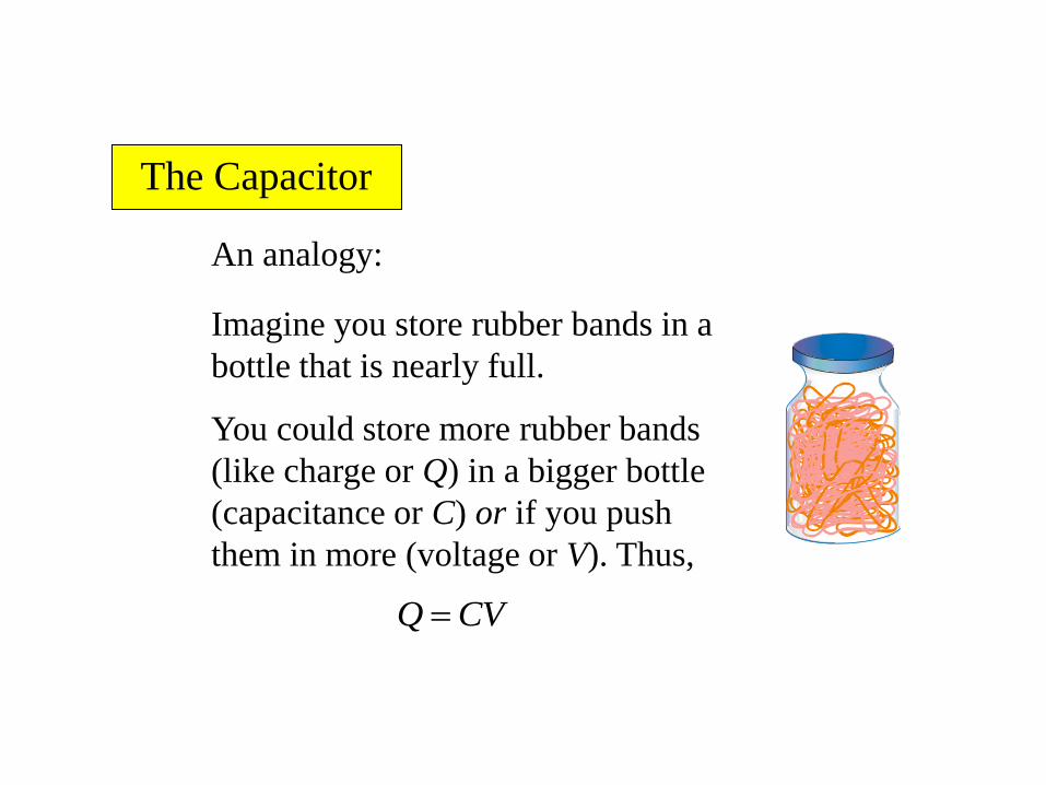
An analogy:
Imagine you store rubber bands in a
bottle that is nearly full.
You could store more rubber bands
(like charge or Q) in a bigger bottle
(capacitance or C) or if you push
them in more (voltage or V). Thus,
Q CV
Capacitance The Capacitor

A capacitor stores energy in the form of an electric field
that is established by the opposite charges on the two
plates. The energy of a charged capacitor is given by the
equation
Capacitance
2
2
1CVW
where
W = the energy in joules
C = the capacitance in farads
V = the voltage in volts
Capacitance The Capacitor
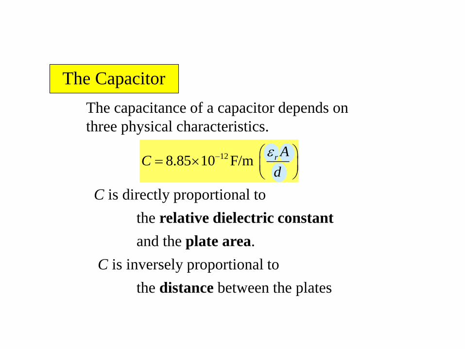
The capacitance of a capacitor depends on
three physical characteristics.
128.85 10 F/m r AC
d
C is directly proportional to
and the plate area.
the relative dielectric constant
C is inversely proportional to
the distance between the plates
Capacitance Capacitance The Capacitor

128.85 10 F/m r AC
d
Find the capacitance of a 4.0 cm diameter
sensor immersed in oil if the plates are
separated by 0.25 mm.
The plate area is
The distance between the plates is
Capacitance
4.0 for oilr
3 2
12
3
4.0 1.26 10 m 8.85 10 F/m
0.25 10 mC
30.25 10 m
178 pF
2 2 3 2π 0.02 m 1.26 10 mA r

Capacitor types
Mica
Mica
Foil
Foil
Mica
Foil
Foil
Mica
Foil
Mica capacitors are small with high working voltage.
The working voltage is the voltage limit that cannot
be exceeded.

Capacitor types
Ceramic disk
Solder
Lead wire solderedto silver elec trode
Ceramicdielectric
Dipped phenolic coating
Silv er elec trodes deposited ontop and bottom of ceramic disk
Ceramic disks are small nonpolarized capacitors They
have relatively high capacitance due to high r.
Capacitor types
Capacitor types
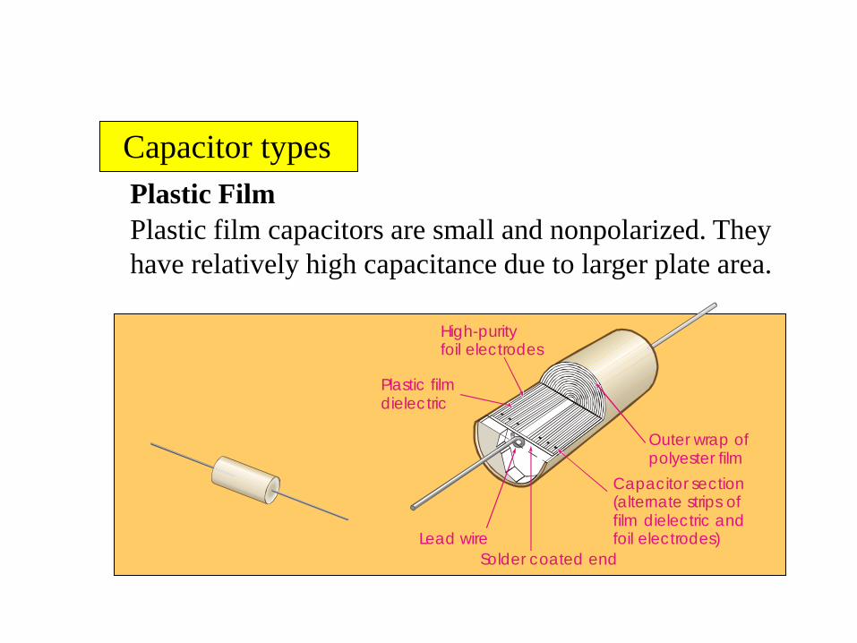
Plastic Film
Lead wire
High-purityfoil electrodes
Plastic filmdielec tric
Outer wrap ofpolyester film
Capacitor section(alternate strips offilm dielectric andfoil electrodes)
Solder coated end
Plastic film capacitors are small and nonpolarized. They
have relatively high capacitance due to larger plate area.
Capacitor types Capacitor types

Capacitor types
Electrolytic (two types)
Symbol for any electrolytic capacitor
Al electrolytic
+
_
Ta electrolytic
Electrolytic capacitors have very high capacitance but
they are not as precise as other types and tend to have
more leakage current. Electrolytic types are polarized.
Capacitor types Capacitor types

Capacitor types
Variable
Variable capacitors typically have small capacitance
values and are usually adjusted manually.
A solid-state device that is used as a variable
capacitor is the varactor diode; it is adjusted with an
electrical signal.
Capacitor types Capacitor types

Capacitor labeling
Capacitors use several labeling methods. Small
capacitors values are frequently stamped on them such
as .001 or .01, which have units of microfarads.
+++
+
VT
TV
TT
47
MF
.022
Electrolytic capacitors have larger
values, so are read as mF. The unit is usually
stamped as mF, but some older ones may be
shown as MF or MMF).
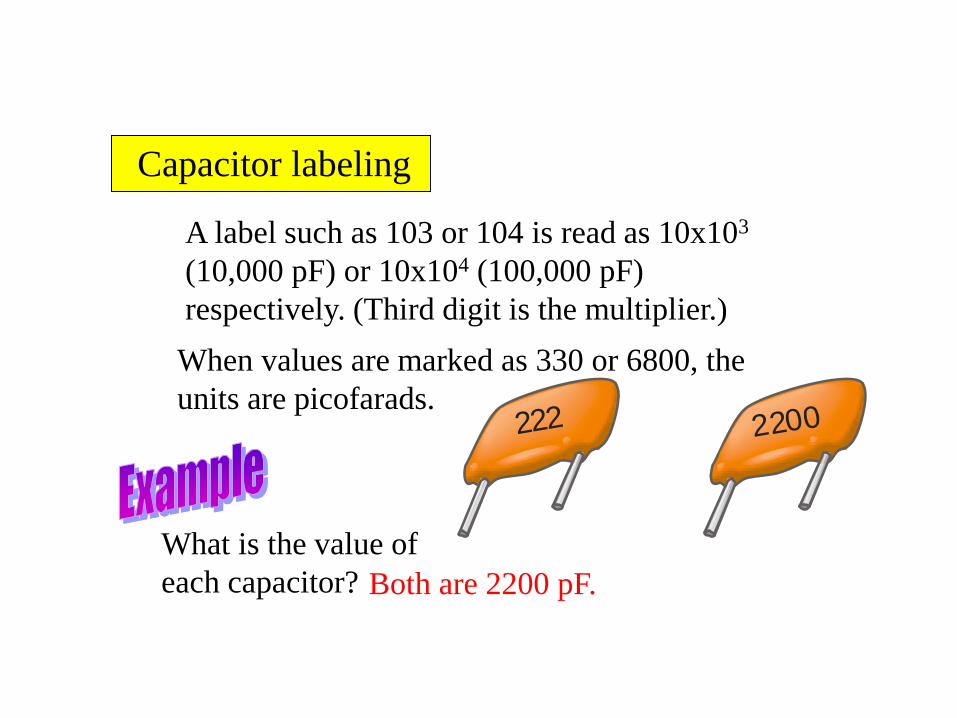
A label such as 103 or 104 is read as 10x103
(10,000 pF) or 10x104 (100,000 pF)
respectively. (Third digit is the multiplier.)
Capacitor labeling
When values are marked as 330 or 6800, the
units are picofarads.
What is the value of
each capacitor? Both are 2200 pF.
222 2200
Capacitor labeling

17
Capacitance, a Recap
• Capacitance occurs whenever electrical
conductors are separated by a dielectric,
or insulating material.
• Applying a voltage to the conductors
displaces the charge within the dielectric.
• Current does not actually flow through the
dielectric.
18
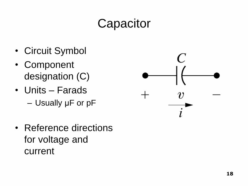
Capacitor
• Circuit Symbol
• Component
designation (C)
• Units – Farads
– Usually μF or pF
• Reference directions
for voltage and
current

19
Voltage-Current Relationship
dvi C
dt

20
Observations
dvi C
dt
The voltage across a capacitor cannot change
instantaneously (the current would be infinite).
If the voltage across the terminals is constant, the
current will be zero.
(looks like an open circuit at DC).
Only a time-varying voltage can produce a
displacement current.
21
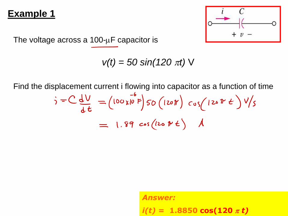
Example 1
The voltage across a 100-mF capacitor is
v(t) = 50 sin(120 t) V
Find the displacement current i flowing into capacitor as a function of time
Answer:
i(t) = 1.8850 cos(120 t)

22
Express the voltage across the capacitor as
a function of the current
0 0
0
( )
( )
0
0
1
1
1( ) ( )
1( ) (0)
v t t
v t t
t
t
t
dvi C
dt
idt Cdv dv idtC
dx idC
v t id v tC
v t id vC
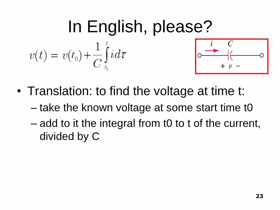
In English, please?
• Translation: to find the voltage at time t:
– take the known voltage at some start time t0
– add to it the integral from t0 to t of the current,
divided by C
23

What this looks like graphically
• At time 0 we measure
capacitor v = 5 V.
• A time varying current is then
applied to the capacitor
• Voltage at any time t is then
found as
v(t) =v(0)+ [area under i from 0 to t]/C
24

25
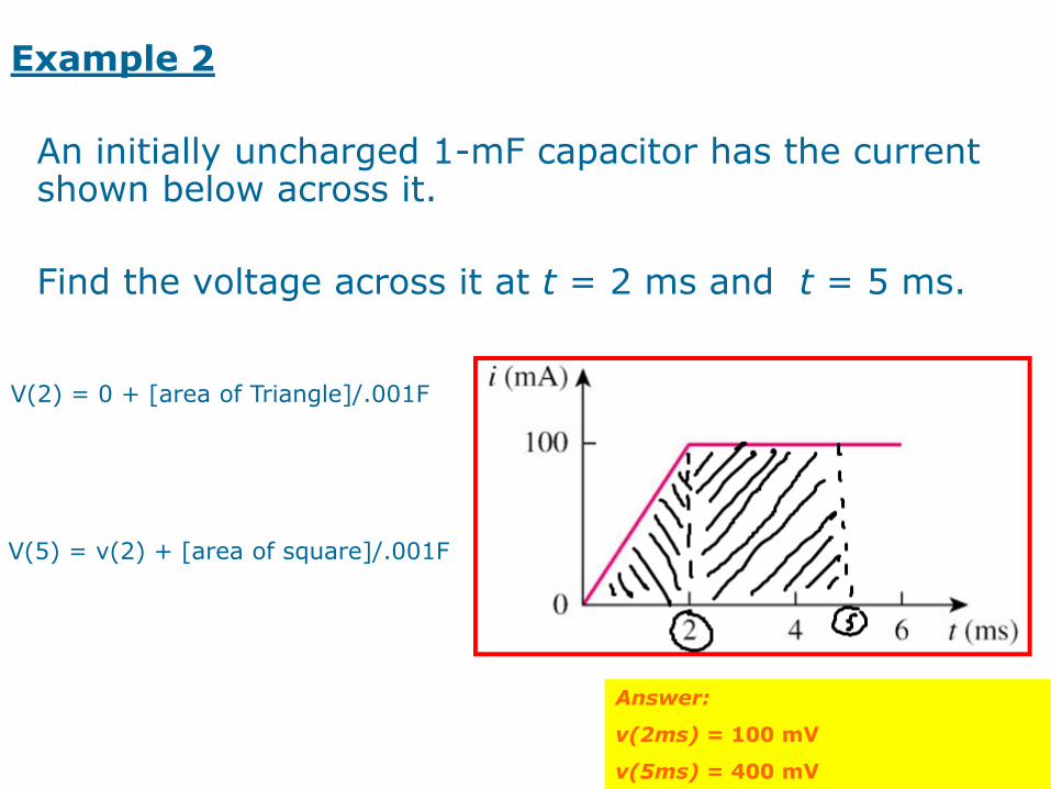
Example 2
An initially uncharged 1-mF capacitor has the current shown below across it.
Calculate the voltage across it at t = 2 ms and t = 5 ms.
Answer:
v(2ms) = 100 mV
v(5ms) = 400 mV
V(2) = 0 + [area of Triangle]/.001F
V(5) = v(2) + [area of square]/.001F

26
Power and Energy for the Capacitor
0
0 0
2
1( )
1
2
t
t
w v
dvp vi Cv
dt
p i id v tC
dw dvCv
dt dt
dw Cvdv
dx C ydy
w Cv

27
Example 6.4
• A voltage pulse described as follows is applied across
the terminals of a 0.5μF capacitor:
• Derive the expressions for the capacitor a) current,
b) power, and c) energy.

28
A) Derive the expressions for the capacitor current

29
B) Derive the expressions for the capacitor power

30
C) Derive the expressions for the capacitor energy

31
Energy is being stored whenever the
power is positive.
Energy is being delivered by the
capacitor whenever the power is
negative.

32
6.2 Series and Parallel Capacitors (1)
• The equivalent capacitance of N parallel-connected capacitors is the sum of the individual capacitances.
Neq CCCC ...21

33
6.2 Series and Parallel Capacitors (2)
• The equivalent capacitance of N series-connected capacitors is the reciprocal of the sum of the reciprocals of the individual capacitances.
Neq CCCC
1...
111
21

34
Example 3
Find the equivalent capacitance seen at the terminals of the circuit in the circuit shown below:
Answer:
Ceq = 40mF
35
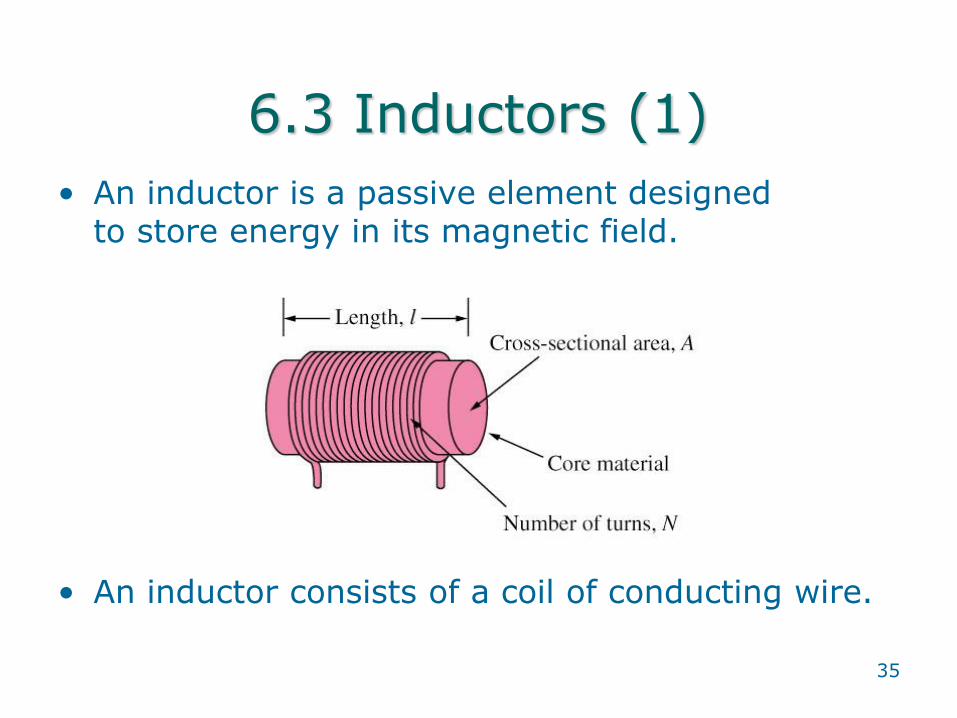
6.3 Inductors (1)
• An inductor is a passive element designed to store energy in its magnetic field.
• An inductor consists of a coil of conducting wire.

Inductance is the property of a conductor to oppose
a change in current. The effect of inductance is
greatly magnified by winding a coil on a magnetic
material.
Inductance
Common symbols for inductors (coils) are
Air core Iron core Ferrite core Variable

Self Inductance
Self-inductance is usually just called inductance,
symbolized by L. Self-inductance is a measure of a coil’s
ability to establish an induced voltage as a result of a
change in its current. The induced voltage always opposes
the change in current, which is basically a statement of
Lenz’s law.
The unit of inductance is the henry (H). One henry is the
inductance of a coil when a current, changing at a rate of
one ampere per second, induces one volt across the coil.
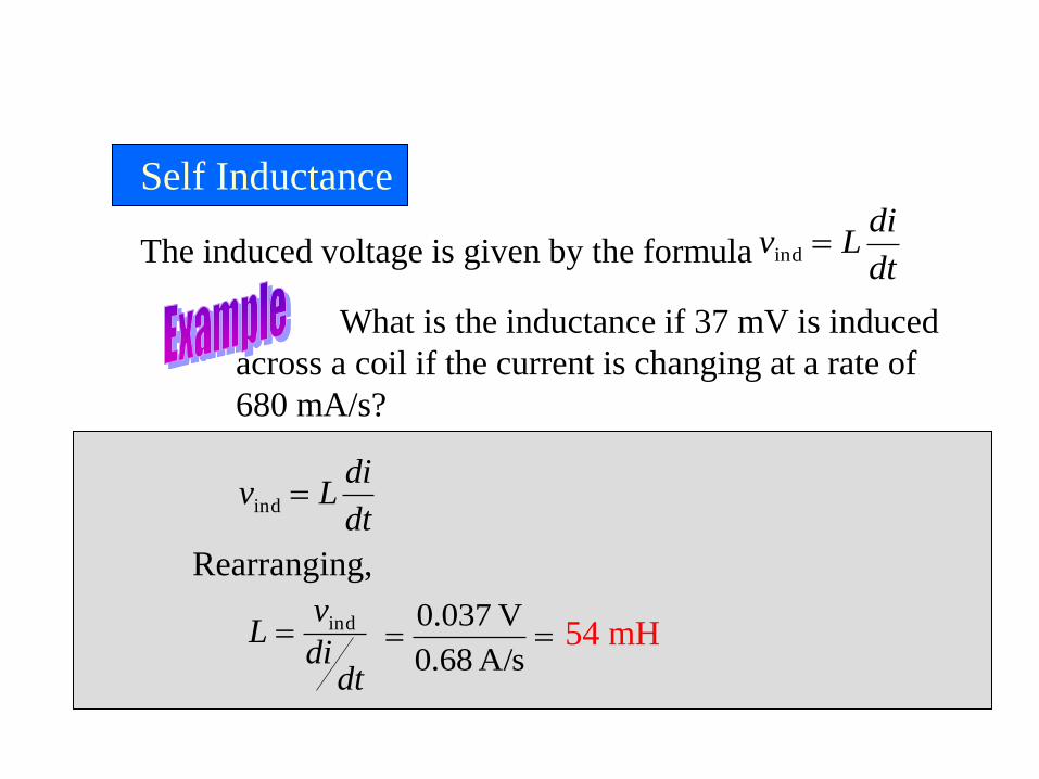
Self Inductance
The induced voltage is given by the formula dt
diLv ind
What is the inductance if 37 mV is induced
across a coil if the current is changing at a rate of
680 mA/s?
54 mH ind
dtdi
vL
dt
diLv ind
Rearranging,
A/s 68.0
V 037.0

Factors affecting inductance
Four factors affect the amount of inductance for a
coil. The equation for the inductance of a coil is 2N A
Ll
m
where
L = inductance in henries
N = number of turns of wire
m = permeability in H/m (same as Wb/At-m)
l = coil length on meters
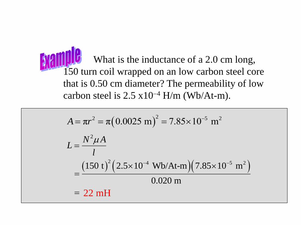
What is the inductance of a 2.0 cm long,
150 turn coil wrapped on an low carbon steel core
that is 0.50 cm diameter? The permeability of low
carbon steel is 2.5 x10⁴ H/m (Wb/At-m).
22 5 2π π 0.0025 m 7.85 10 mA r
2N AL
l
m
22 mH
2 4 5 2150 t 2.5 10 Wb/At-m 7.85 10 m
0.020 m
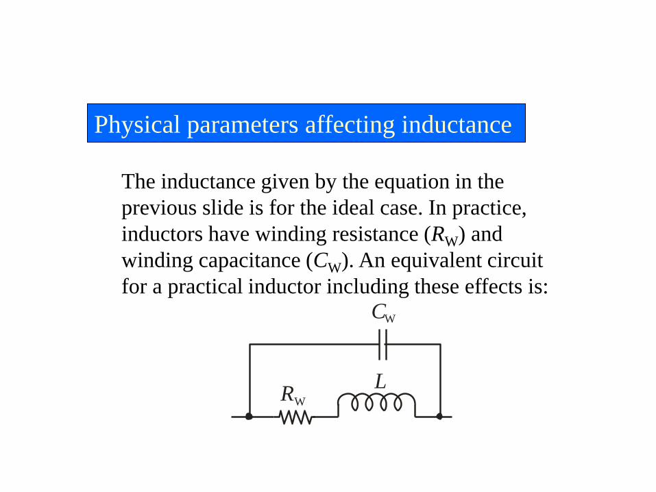
Physical parameters affecting inductance
The inductance given by the equation in the
previous slide is for the ideal case. In practice,
inductors have winding resistance (RW) and
winding capacitance (CW). An equivalent circuit
for a practical inductor including these effects is:
LRW
CW

Recall Lenz’s law states,
When the current through a coil changes, an
induced voltage is created across the coil that
always opposes the change in current.
In a practical circuit, the current can change
because of a change in the load as shown in
the following circuit example...
Lenz’s law

Lenz’s law
A basic circuit to demonstrate Lenz’s law is shown.
Initially, the SW is open and there is a small
current in the circuit through L and R1.
R1
SW
R2VS
L
+
+

SW closes and immediately a voltage appears
across L that tends to oppose any change in current.
R1
SW
R2VS
L
+
+
+Initially, the meter
reads same current
as before the switch
was closed.
Lenz’s law

After a time, the current stabilizes at a higher level
(due to R2) as the voltage decays across the coil.
+
R1
SW
R2VS
L
+
Lenz’s law
Later, the meter
reads a higher
current because of
the load change.

Practical inductors
Inductors come in a variety of sizes. A few
common ones are shown here.
Encapsulated Torroid coil Variable
47
Inductance
• Inductor
– A coil of wire wrapped around a supporting
core (magnetic or non-magnetic)
– The time-varying current in the wire produces
a time-varying magnetic field around the wire
– A voltage is induced in any conductor linked
by the magnetic field
– Inductance relates the induced voltage to the
current

48
Inductor
• Circuit Symbol
• Component
designation (L)
• Units -- Henry(s)
– Usually mH or μH
• Reference directions
for voltage and
current

49
Voltage-Current Relationship
div L
dt
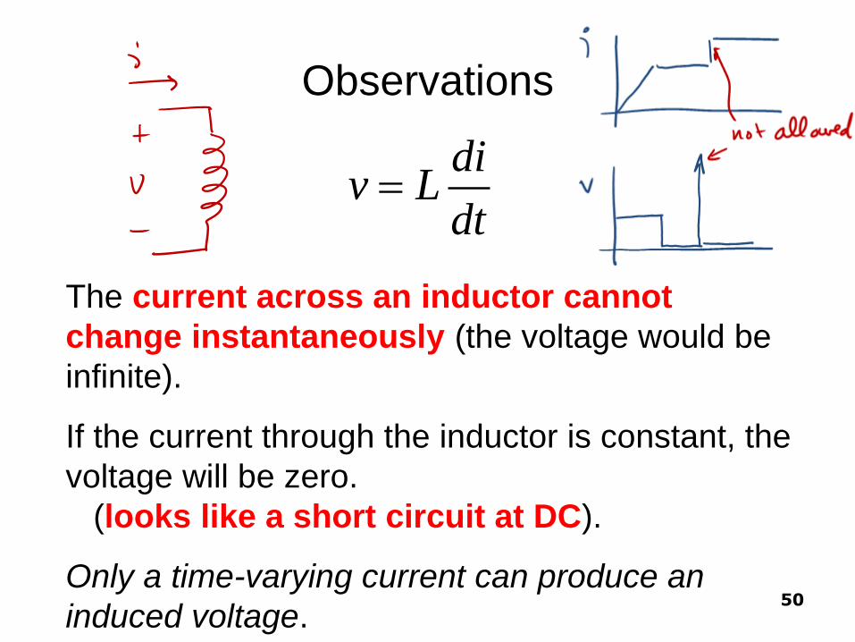
The current across an inductor cannot
change instantaneously (the voltage would be
infinite).
If the current through the inductor is constant, the
voltage will be zero.
(looks like a short circuit at DC).
Only a time-varying current can produce an
induced voltage. 50
Observations
div L
dt

51
Current in an inductor in terms of the
Voltage across the inductor
0 0
0 0
( )
( )
0
1 1( ) ( ) (0)
i tt
t i t
t t
t t
div L
dt
divdt Ldi L dt
dt
vdt Ldi
vd L dx
i t vd i t vd iL L

Again, in English
• Translation: to find the current at time t:
– take the known current at some start time t0
– add to it the integral from t0 to t of the voltage,
divided by L
52

What this looks like graphically
• At time 0 we measure
inductor i = 5 A.
• A time varying voltage is then
applied to the inductor
• Current at any time t is then
found as
i(t) =i(0)+ [area under v from 0 to t]/L
53

54
Power and Energy in an Inductor
0
0
0 0
2
1( )
1
2
t
t
w i
dip vi Li
dt
p vi v vd i tL
dw dip Li
dt dt
dw Lidi
dx L ydy
w Li
55
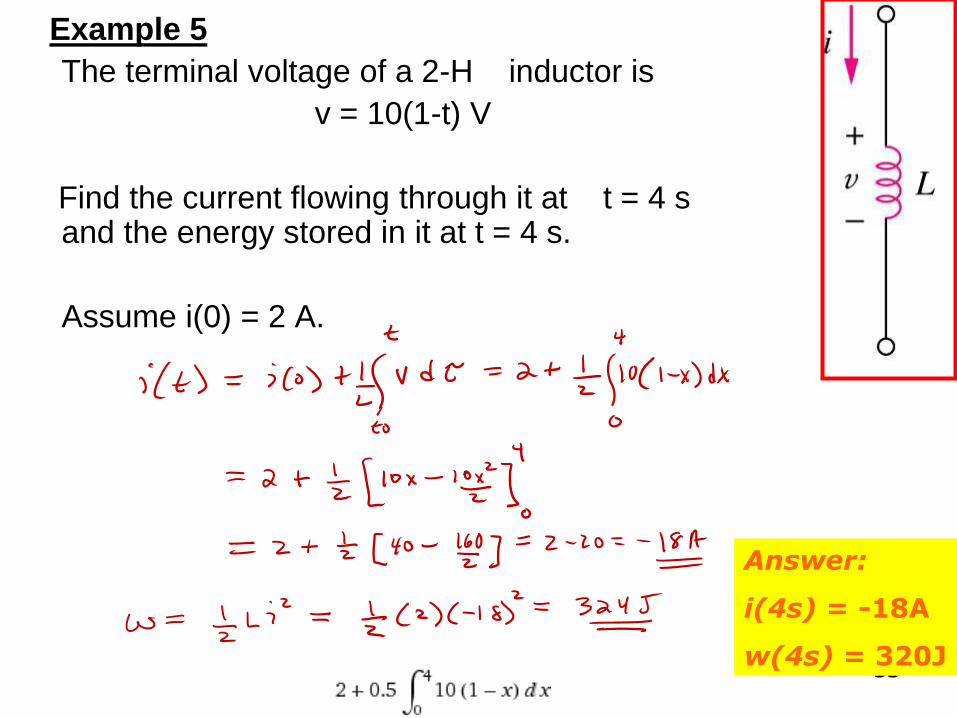
Example 5
The terminal voltage of a 2-H inductor is
v = 10(1-t) V
Find the current flowing through it at t = 4 s and the energy stored in it at t = 4 s.
Assume i(0) = 2 A.
Answer:
i(4s) = -18A
w(4s) = 320J
56
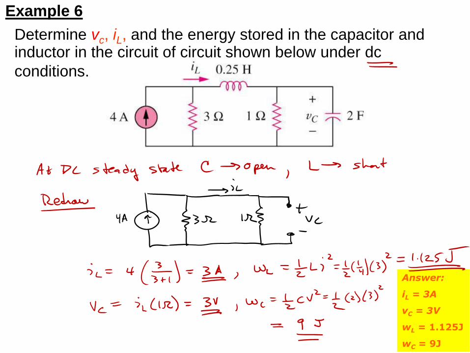
Example 6
Determine vc, iL, and the energy stored in the capacitor and inductor in the circuit of circuit shown below under dc
conditions.
Answer:
iL = 3A
vC = 3V
wL = 1.125J
wC = 9J

57
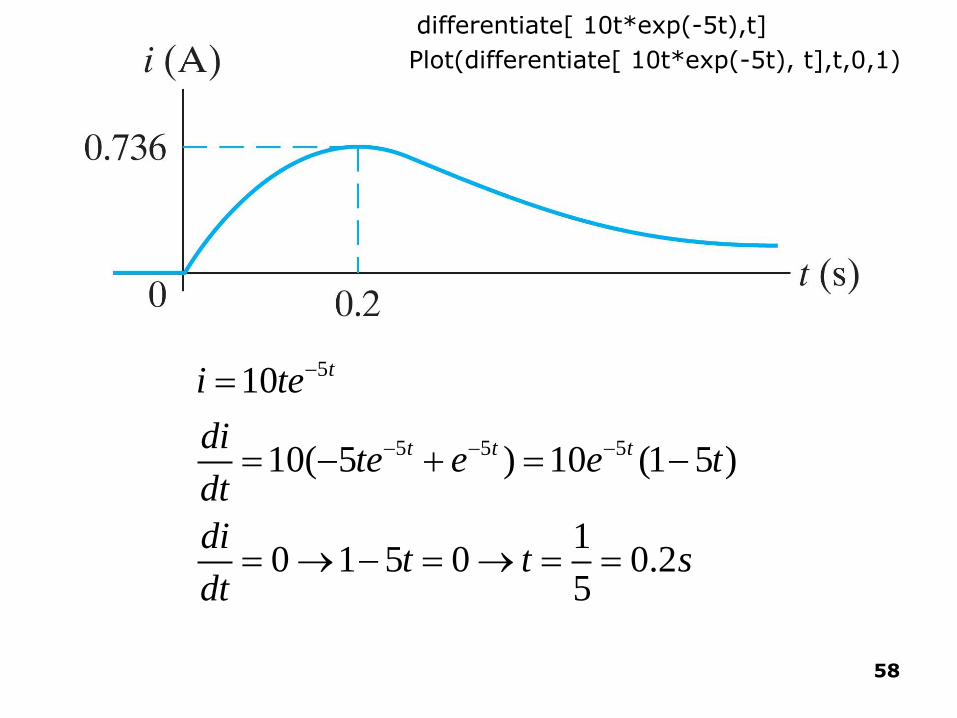
Example 6.1 – Sketch current, find max
using Wolfram Alpha
• First, sketch the current waveform.
• At what instant of time is the current maximum?
• Wolfram Alpha: Plot[ 10t*exp(-5t), t, 0, 1]
58
5
5 5 5
10
10( 5 ) 10 (1 5 )
10 1 5 0 0.2
5
t
t t t
i te
dite e e t
dt
dit t s
dt
Plot(differentiate[ 10t*exp(-5t), t],t,0,1)
differentiate[ 10t*exp(-5t),t]

59
Example 6.2 Using Derivative formula Given: current thru inductor
Find: voltage across inductor
5
5 5
10
(0.1)10 (1 5 ) (1 5 )
t
t t
i te
div L e t e t
dt

60
Are the voltage and current at maximum at
the same time?

61
At what instant of time does the voltage
change polarity?
The voltage changes polarity
when the current passes
through its maximum value
and the slope changes sign.

62
Is there ever an instantaneous change in
voltage across the inductor? If so, when?
Yes.
The voltage across the inductor changes
instantaneously at t=0.

Using wolframalpha.com to
differentiate • diff[ f(x), x ] takes derivative of some f(x) wrt x
• diff[10t*exp(-5t),t]
– Use * when needed to clarify
– Use exp( ) to raise e to some exponent
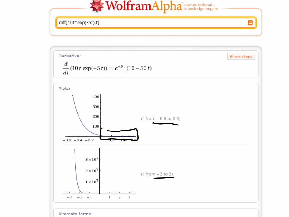

If you don’t like the plot range, hover mouse over letter A below plot,
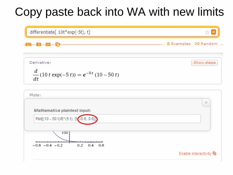
Copy paste back into WA with new limits
67
Example 6.3
• Plot i, v, p, and w for Example 6.3. Line
up the plots vertically to allow easy
assessment of each variable’s behavior.
• In what time interval is energy being
stored in the inductor?
• In what time interval is energy being
extracted from the inductor?

68
Energy is being stored
when power is >0.
An increasing energy
curve indicates that
energy is being stored in
the inductor.
Energy is being extracted
when power is <0.
A decreasing energy curve
indicates that energy is
being extracted from the
inductor
69
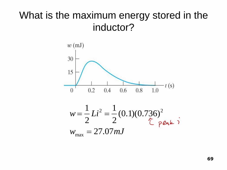
What is the maximum energy stored in the
inductor?
2 2
max
1 1(0.1)(0.736)
2 2
27.07
w Li
w mJ

70
Example 6.4 Using the integral formula Given: voltage across inductor
Find: current through inductor
• Sketch the voltage as a function of time.
• Find the inductor current as a function of time.
• Sketch the current as a function of time.

Integrating with Wolfram Alpha
• Basic indefinite integral:
– Integrate[x^2, {x}]
• Basic definite integral
– Integrate[x^2,{x,0,5}]
Integrating with Wolfram Alpha
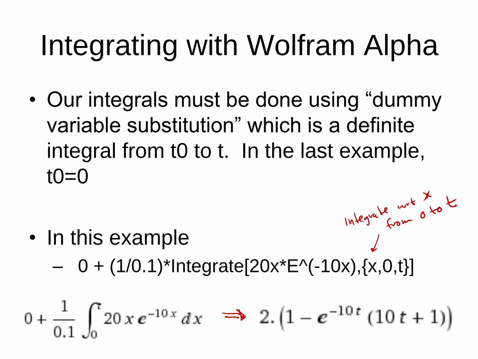
• Our integrals must be done using “dummy
variable substitution” which is a definite
integral from t0 to t. In the last example,
t0=0
• In this example
– 0 + (1/0.1)*Integrate[20x*E^(-10x),{x,0,t}]
=

73
0
10
0
10
0
10 10
1( ) (0)
1( ) 20 0
0.1
( ) 200 (10 1)100
( ) 2(1 10 )
t
t
t
t t
i t vd iL
i t e d
ei t
i t te e

74
10 10( ) 2(1 10 )t ti t te e
Current approaches 2A as t ∞

75
6.4 Series and Parallel Inductors (1)
• The equivalent inductance of series-connected inductors is the sum of the individual inductances.
Neq LLLL ...21

76
6.4 Series and Parallel Inductors (2)
• The equivalent capacitance of parallel inductors is the reciprocal of the sum of the reciprocals of the individual inductances.
Neq LLLL
1...
111
21
77
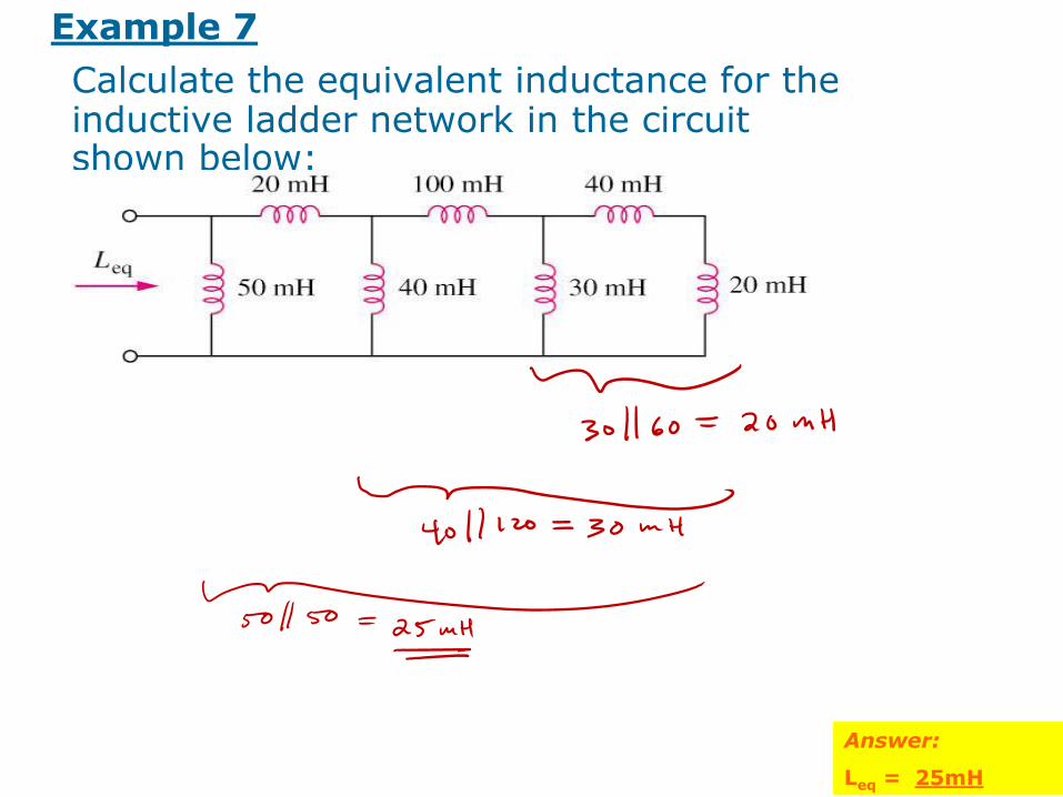
Example 7
Calculate the equivalent inductance for the inductive ladder network in the circuit shown below:
Answer:
Leq = 25mH

78
6.4 Series and Parallel Capacitors (4)
• Current and voltage relationship for R, L, C
+
+
+

Analog Integration http://ecee.colorado.edu/~mathys/ecen1400/labs/lab06/index.html
79
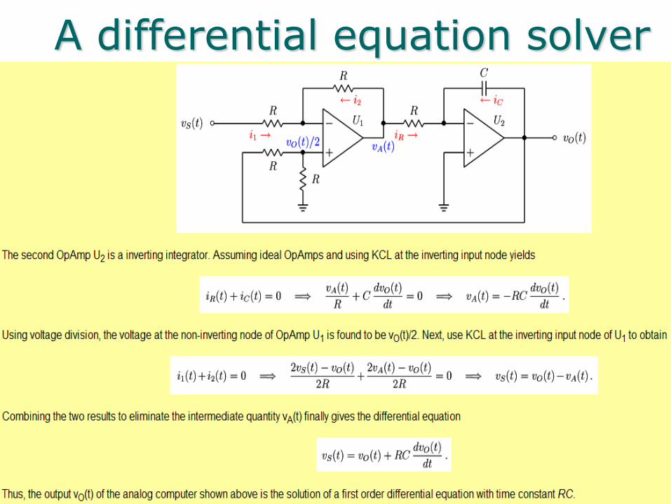
A differential equation solver
80

HANDOUTS
81

82
Example 1
The voltage across a 100-mF capacitor is
v(t) = 50 sin(120 t) V
Find the displacement current i flowing into capacitor as a function
of time
Answer:
i(t) = 1.8850 cos(120 t)
83
Example 2
An initially uncharged 1-mF capacitor has the current shown below across it.
Find the voltage across it at t = 2 ms and t = 5 ms.
Answer:
v(2ms) = 100 mV
v(5ms) = 400 mV
V(2) = 0 + [area of Triangle]/.001F
V(5) = v(2) + [area of square]/.001F

84
Example 3
Find the equivalent capacitance seen at the terminals of the circuit in the circuit shown below:
Answer:
Ceq = 40mF

85
Example 5
The terminal voltage of a 2-H inductor is
v = 10(1-t) V
Find the current flowing through it at t = 4 s and the energy stored in it at t = 4 s.
Assume i(0) = 2 A.
Answer:
i(4s) = -18A
w(4s) = 320J

86
Example 6
Determine vc, iL, and the energy stored in the capacitor and inductor in the circuit of circuit shown
below under dc conditions.
Answer:
iL = 3A
vC = 3V
wL = 1.125J
wC = 9J

87
Example 7
Calculate the equivalent inductance for the inductive ladder network in the circuit shown below:
Answer:
Leq = 25mH