
EDU CAD Instructor Guide 2015 ENG SV
39
Engineering Design and Technology Series CAD Instructor Guide Dassault Systèmes SolidWorks Corporation, 175 Wyman Street, Waltham, Massachusetts 02451 USA Phone: +1-800-693-9000 Outside the U.S.: +1-781-810-5011 Fax: +1-781-810-3951 Email: [email protected] Web: http://www.solidworks.com/education
-
Upload
jaganathanbe -
Category
Documents
-
view
17 -
download
4
description
cad instruction
Transcript of EDU CAD Instructor Guide 2015 ENG SV

Engineering Designand Technology Series
CAD Instructor Guide
Dassault Systèmes SolidWorks Corporation,175 Wyman Street,Waltham, Massachusetts 02451 USAPhone: +1-800-693-9000
Outside the U.S.: +1-781-810-5011Fax: +1-781-810-3951
Email: [email protected]: http://www.solidworks.com/education

© 1995-2013, Dassault Systèmes SolidWorks Corporation, a Dassault Systèmes S.A. company, 175 Wyman Street, Waltham, Mass. 02451 USA. All Rights Reserved.
The information and the software discussed in this document are subject to change without notice and are not commitments by Dassault Systèmes SolidWorks Corporation (DS SolidWorks).
No material may be reproduced or transmitted in any form or by any means, electronically or manually, for any purpose without the express written permission of DS SolidWorks.
The software discussed in this document is furnished under a license and may be used or copied only in accordance with the terms of the license. All warranties given by DS SolidWorks as to the software and documentation are set forth in the license agreement, and nothing stated in, or implied by, this document or its contents shall be considered or deemed a modification or amendment of any terms, including warranties, in the license agreement.
Patent Notices
SolidWorks® 3D mechanical CAD software is protected by U.S. Patents 5,815,154; 6,219,049; 6,219,055; 6,611,725; 6,844,877; 6,898,560; 6,906,712; 7,079,990; 7,477,262; 7,558,705; 7,571,079; 7,590,497; 7,643,027; 7,672,822; 7,688,318; 7,694,238; 7,853,940, 8,305,376, and foreign patents, (e.g., EP 1,116,190 B1 and JP 3,517,643).
eDrawings® software is protected by U.S. Patent 7,184,044; U.S. Patent 7,502,027; and Canadian Patent 2,318,706.
U.S. and foreign patents pending.
Trademarks and Product Names for SolidWorks Products and ServicesSolidWorks, 3D ContentCentral, 3D PartStream.NET, eDrawings, and the eDrawings logo are registered trademarks and FeatureManager is a jointly owned registered trademark of DS SolidWorks.
CircuitWorks, FloXpress, PhotoView 360, and TolAnalyst, are trademarks of DS SolidWorks.
FeatureWorks is a registered trademark of Geometric Ltd.
SolidWorks 2015, SolidWorks Enterprise PDM, SolidWorks Workgroup PDM, SolidWorks Simulation, SolidWorks Flow Simulation, eDrawings, eDrawings Professional, SolidWorks Sustainability, SolidWorks Plastics, SolidWorks Electrical, and SolidWorks Composer are product names of DS SolidWorks.
Other brand or product names are trademarks or registered trademarks of their respective holders.
COMMERCIAL COMPUTER SOFTWARE - PROPRIETARYThe Software is a "commercial item" as that term is defined at 48 C.F.R. 2.101 (OCT 1995), consisting of "commercial computer software" and "commercial software documentation" as such terms are used in 48 C.F.R. 12.212 (SEPT 1995) and is provided to the U.S. Government (a) for acquisition by or on behalf of civilian agencies, consistent with the policy set forth in 48 C.F.R. 12.212; or (b) for acquisition by or on behalf of units of the department of Defense, consistent with the policies set forth in 48 C.F.R. 227.7202-1 (JUN 1995) and 227.7202-4 (JUN 1995).
In the event that you receive a request from any agency of the U.S. government to provide Software with rights beyond those set forth above, you will notify DS SolidWorks of the scope of the request and DS SolidWorks will have five (5) business days to, in its sole discretion, accept or reject such request. Contractor/Manufacturer: Dassault Systèmes SolidWorks Corporation, 175 Wyman Street, Waltham, Massachusetts 02451 USA.
Copyright Notices for SolidWorks Standard, Premium, Professional, and Education ProductsPortions of this software © 1986-2013 Siemens Product Lifecycle Management Software Inc. All rights reserved.
This work contains the following software owned by Siemens Industry Software Limited:
D-Cubed™ 2D DCM © 2013. Siemens Industry Software Limited. All Rights Reserved.
D-Cubed™ 3D DCM © 2013. Siemens Industry Software Limited. All Rights Reserved.
D-Cubed™ PGM © 2013. Siemens Industry Software Limited. All Rights Reserved.
D-Cubed™ CDM © 2013. Siemens Industry Software Limited. All Rights Reserved.
D-Cubed™ AEM © 2013. Siemens Industry Software Limited. All Rights Reserved.
Portions of this software © 1998-2013 Geometric Ltd.
Portions of this software incorporate PhysX™ by NVIDIA 2006-2010.
Portions of this software © 2001-2013 Luxology, LLC. All rights reserved, patents pending.
Portions of this software © 2007-2013 DriveWorks Ltd.
Copyright 1984-2010 Adobe Systems Inc. and its licensors. All rights reserved. Protected by U.S. Patents 5,929,866; 5,943,063; 6,289,364; 6,563,502; 6,639,593; 6,754,382; Patents Pending.
Adobe, the Adobe logo, Acrobat, the Adobe PDF logo, Distiller and Reader are registered trademarks or trademarks of Adobe Systems Inc. in the U.S. and other countries.
For more DS SolidWorks copyright information, see Help > About SolidWorks.
Copyright Notices for SolidWorks Simulation ProductsPortions of this software © 2008 Solversoft Corporation.
PCGLSS © 1992-2013 Computational Applications and System Integration, Inc. All rights reserved.
Copyright Notices for SolidWorks Enterprise PDM Product
Outside In® Viewer Technology, © 1992-2012 Oracle © 2011, Microsoft Corporation. All rights reserved.
Copyright Notices for eDrawings ProductsPortions of this software © 2000-2013 Tech Soft 3D.
Portions of this software © 1995-1998 Jean-Loup Gailly and Mark Adler.
Portions of this software © 1998-2001 3Dconnexion.
Portions of this software © 1998-2013 Open Design Alliance. All rights reserved.
Portions of this software © 1995-2012 Spatial Corporation.
The eDrawings® for Windows® software is based in part on the work of the Independent JPEG Group.
Portions of eDrawings® for iPad® copyright © 1996-1999 Silicon Graphics Systems, Inc.
Portions of eDrawings® for iPad® copyright © 2003-2005 Apple Computer Inc.
Document Number:

Contents
Introduction v
Lesson 1: Using the Interface 1
Lesson 2: Basic Functionality 17
Lesson 3: The 40-Minute Running Start 47
Lesson 4: Assembly Basics 67
Lesson 5: SolidWorks Toolbox Basics 99
Lesson 6: Drawing Basics 121
Lesson 7: SolidWorks eDrawings Basics 149
Lesson 8: Design Tables 171
Lesson 9: Revolve and Sweep Features 197
Lesson 10: Loft Features 221
Lesson 11: Visualization 241
Lesson 12: SolidWorks Sustainability 261
Lesson 13: SolidWorks SimulationXpress 279
Glossary 297
Appendix A: SolidWorks Certification 303
Appendix B: Certified SolidWorks Associate Sample Exam 307
Appendix C: STEM Course Outline 317
Appendix D: NGSS and CCSS Standards 323
Appendix E: Curriculum Layout Options 325
CAD Instructor Guide iii

Contents
iv CAD Instructor Guide

i
Introduction
To the Teacher
The CAD Instructor Guide and its supporting materials are designed to assist you in teaching SolidWorks in an academic setting. This guide offers a competency-based approach to teaching 3D design concepts and techniques.
Each lesson in the CAD Instructor Guide has corresponding pages in the CAD Student Guide (available as PDFs from the Design Library tab on the Task Pane. Expand SolidWorks Content, SolidWorks Educator Curriculum, Curriculum, SolidWorks Student Guide). The CAD Instructor Guide is annotated with discussion points, suggestions for class demonstrations, and explanatory information related to the exercises and projects. Also in this guide are answer keys for assessments, worksheets, and quizzes.
SolidWorks Tutorials
The CAD Instructor Guide is a companion resource and supplement for the SolidWorks Tutorials. Many of the exercises in the CAD Student Guide use material from the SolidWorks Tutorials.
Accessing the SolidWorks Tutorials
To start the SolidWorks Tutorials, click Help, SolidWorks Tutorials. The SolidWorks window is resized and a second window appears next to it with a list of the available tutorials. There are over 40 lessons in the SolidWorks Tutorials. As you move the pointer over the links, an illustration of the tutorial will appear at the bottom of the window. Click the desired link to start that tutorial.
TIP: When you use SolidWorks Simulation to perform static engineering analysis, click Help, SolidWorks Simulation, Tutorials to access over 50 lessons and over 80 verification problems. Click Tools, Add-ins to activate SolidWorks Simulation.
CAD Instructor Guide v
Introduction
Conventions
Set your screen resolution to at least 1280x1024 for optimal viewing of the tutorials.
The following icons appear in the tutorials:
Click the link below “Next Topic:” to move to the next screen in the tutorial.
Represents a note or tip. It is not a link; the information is next to the icon. Notes and tips provide time-saving steps and helpful hints.
You can click most buttons that appear in the lessons to flash the corresponding SolidWorks button.
Open File automatically opens the file.
A closer look at... links to more information about a topic. Although not required to complete the tutorial, it offers more detail on the subject.
Why did I... links to more information about a procedure, and the reasons for the method given. This information is not required to complete the tutorial.
Video: ... demonstrates with a video.
Printing the SolidWorks Tutorials
If you like, you can print the SolidWorks Tutorials by following this procedure:
1 On the tutorial navigation toolbar, click Show.
This displays the table of contents for the SolidWorks Tutorials.
2 Right-click the book representing the lesson you wish to print and select Print... from the shortcut menu.
The Print Topics dialog box appears.
3 Select Print the selected heading and all subtopics, and click OK.
4 Repeat this process for each lesson that you want to print.
Educator Resources link
The Instructors Curriculum link on the SolidWorks Resources tab of the Task Pane includes substantial supporting materials to aid in your course presentation. Accessing this page requires a login account for the SolidWorks Customer Portal. You can use this course as is or you can select the pieces of it that meet your class needs. These supporting materials afford you flexibility in scope, depth, and presentation.
vi CAD Instructor Guide

Introduction
Before You Begin
If you have not done so already, copy the companion files for the lessons onto your computer before you begin this project.
1 Start SolidWorks.
Using the Start menu, start the SolidWorks application.
2 SolidWorks Content.
Click SolidWorks Resources to open the SolidWorks Resources Task Pane.
Click on the Instructors Curriculum link which will take you to the SolidWorks Customer Portal web page.
Click Educator Resources, under Download. Accessing this page requires a login account for the SolidWorks Customer Portal.
Here you will find the zip file containing the teacher companion files: Teacher Lesson/Model Files.
3 Download the zip file.
4 Open the zip file.
Browse to the folder where you saved the zip file in step 3 and double-click the zip file.
5 Click Extract.
Browse to the location where you want to save the files. The system automatically creates folders for the sample files in whatever location you specify. For example, you might want to save it in My Documents.
Using This Course
This course is not just this book. The CAD Instructor Guide is the focal point of the SolidWorks course — the road map for it. The supporting materials that are on the Educator Resources link and the SolidWorks Tutorials give you a lot of flexibility in how you present the course.
Learning 3D design is an interactive process. Students learn best when they can explore the practical applications of the concepts that they learn. This course has many activities and exercises that enable students to put design concepts into practice. Using the provided files, they can do so quickly.
The lesson plans for this course are designed to balance lecture and hands-on learning. There are also assessments and quizzes that give you additional measures of student progress.
TIP: Remember the location of these files.
CAD Instructor Guide vii

Introduction
Before Presenting the Lectures
Verify that the SolidWorks software is loaded and running on your classroom/lab computers in accordance with your SolidWorks license.
Download and unzip the files from the Educator Resources link.
Print copies of CAD Student Guide for each student.
Work through each of the labs yourself. This is not only to verify that you understand how they work, but to explore. Often there are different ways to accomplish a task.
Lesson Plans
Each lesson plan contains the following components:
Goals of the Lesson — Clear objectives for the lesson.
Before Beginning the Lesson — Prerequisites, if any, for the current lesson.
Resources for This Lesson — Tutorials that correspond to the lesson.
Review of Previous Lesson — Students reflect back on the material and models described in the previous lesson with questions and examples. Ask these questions of your students to reinforce concepts.
Lesson Outline — Describes the major concepts explored in each lesson.
Competencies — Lists the competencies that students develop as they learn the material presented in the lesson.
In Class Discussion — Topics for discussion to explain some concepts in the lesson.
Active Learning Exercises — Students create models. Some of these exercises are from CAD Student Guide. Most are from the SolidWorks Tutorials.
5-minute Assessments — These review the concepts developed in the outline of the lesson and the active learning exercises. Questions are presented in the CAD Student Guide and they may be answered in class or for homework. You can use the 5-minute assessment questions as verbal or written exercises. Space is provided in the CAD Student Guide for answers. These are check points for students before they move on to the additional exercises and projects.
Additional Exercises and Projects — Additional exercises and projects are at the end of each lesson. These exercises and projects were developed from suggestions made by students and teachers.
More to Explore — Since students learn at different rates, some lessons also have advanced or related exercises that you can assign to all students or just students who have finished the other material of the lesson ahead of the class.
Note: Mathematics is also explored through a series of applied problems. For example: students design a coffee mug and determine how much liquid it holds. Does the answer make sense?
viii CAD Instructor Guide

Introduction
Lesson Quizzes — Fill in the blank, true/false and short answer questions compose the lesson quizzes. The lesson quiz master and answer key are only available in the CAD Instructor Guide.
Lesson Summary — Quick recap of the main points of the lesson.
Microsoft® PowerPoint® Slides — There are prepared Microsoft PowerPoint slides to explain each lesson. These slides are provided to you electronically on the Educator Resources link. These reproducible pages can also be used to create handouts.
Syllabus
Here is an overview of the material covered in each lesson:
Lesson Outcome for Students Assessments
Lesson 1: Using the Interface • Become familiar with Microsoft Windows
• Become familiar with the SolidWorks user interface
• 5 minute assessment• Vocabulary worksheet• Lesson Quiz
Lesson 2: Basic Functionality • Develop an understanding of 3D modeling and recognition of an object in 3D space
• Apply 2D sketch geometry, rectangle, circle, and dimensions
• Understand 3D features that add and remove geometry including Extruded Base, Extruded Cut, Fillet and Shell
• Create the Box part
• 5 minute assessment• Vocabulary worksheet• Lesson Quiz• Additional Exercises: Design a
Switch Plate• Optional materials for Switch
Plate: Cardboard, construction paper or foam board 120mmx80mm for each student, tape or glue, cutting tools, ruler
• Optional materials for Box: For milled wood 100mmx60mmx50mm for each box. (Note: Cardboard sheets and tape can also be used)
CAD Instructor Guide ix

Introduction
Lesson 3: The 40-Minute Running Start
• Reinforce the understanding of 3D features that add and remove geometry
• Apply 2D sketch geometry, rectangle, circle, and dimensions
• Create the Tutor1 part
• 5 minute assessment• Unit conversion worksheet• Material volume assessment• Lesson Quiz• Additional Exercises:
Modifying the Tutor1 part• Additional Exercises: CD Jewel
Case and Storage Box parts• Optional materials: cardboard
or foam board, tape, wood (mill or precut pieces required) 29mmx17mmx18mm for each storage box
Lesson 4: Assembly Basics • Develop an understanding of 3D assembly modeling by combining Tutor1 part with Tutor2 part
• Apply 2D sketch tools to offset geometry and project geometry to the sketch plane
• Create Tutor2 part and Tutor assembly
• 5 minute assessment• Vocabulary worksheet• Lesson Quiz• Review of fastener selection• Additional Exercises: Design a
Switchplate assembly, Storage Box assembly, and Claw Mechanism assembly
• Optional materials: screws for switchplate part, roughly 3.5mm diameter
• A variety of fasteners to discuss design and manufacturing parameters for a product
Lesson 5: SolidWorks Toolbox Basics
• Develop an understanding of SolidWorks Toolbox, a component library of standard parts
• Understand how library components are utilized in an assembly
• Modify SolidWorks Toolbox part definitions
• 5 minute assessment• Vocabulary worksheet• Lesson Quiz• Assemble a standard Toolbox
pan head screw to the switchplate
• Additional Exercises: Add fasteners to the bearing block assembly
• Optional materials: Variety of fasteners. For Switch Plate, #6-32 Pan Head
Lesson 6: Drawing Basics • Understand basic drawing concepts
• Apply drawing standards to part and assembly drawings
• Create a drawing template• Create Tutor1 drawing for part
and assembly
• 5 minute assessment• Lesson Quiz• Additional Exercises: Create a
drawing for Tutor2, the storage box, and the switchplate
Lesson Outcome for Students Assessments
x CAD Instructor Guide
Introduction
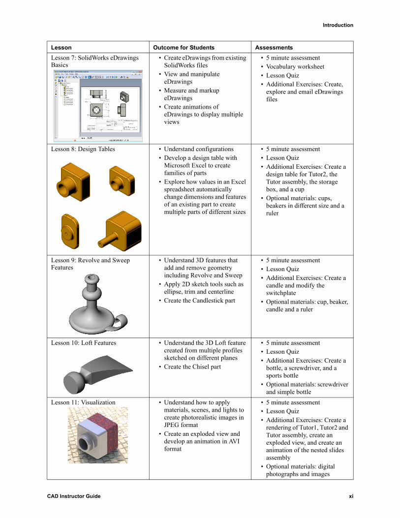
Lesson 7: SolidWorks eDrawings Basics
• Create eDrawings from existing SolidWorks files
• View and manipulate eDrawings
• Measure and markup eDrawings
• Create animations of eDrawings to display multiple views
• 5 minute assessment• Vocabulary worksheet• Lesson Quiz• Additional Exercises: Create,
explore and email eDrawings files
Lesson 8: Design Tables • Understand configurations• Develop a design table with
Microsoft Excel to create families of parts
• Explore how values in an Excel spreadsheet automatically change dimensions and features of an existing part to create multiple parts of different sizes
• 5 minute assessment• Lesson Quiz• Additional Exercises: Create a
design table for Tutor2, the Tutor assembly, the storage box, and a cup
• Optional materials: cups, beakers in different size and a ruler
Lesson 9: Revolve and Sweep Features
• Understand 3D features that add and remove geometry including Revolve and Sweep
• Apply 2D sketch tools such as ellipse, trim and centerline
• Create the Candlestick part
• 5 minute assessment• Lesson Quiz• Additional Exercises: Create a
candle and modify the switchplate
• Optional materials: cup, beaker, candle and a ruler
Lesson 10: Loft Features • Understand the 3D Loft feature created from multiple profiles sketched on different planes
• Create the Chisel part
• 5 minute assessment• Lesson Quiz• Additional Exercises: Create a
bottle, a screwdriver, and a sports bottle
• Optional materials: screwdriver and simple bottle
Lesson 11: Visualization • Understand how to apply materials, scenes, and lights to create photorealistic images in JPEG format
• Create an exploded view and develop an animation in AVI format
• 5 minute assessment• Lesson Quiz• Additional Exercises: Create a
rendering of Tutor1, Tutor2 and Tutor assembly, create an exploded view, and create an animation of the nested slides assembly
• Optional materials: digital photographs and images
Lesson Outcome for Students Assessments
CAD Instructor Guide xi

Introduction
Supporting Course Materials
The following supporting course materials are provided to you via the Educators Resources link of the SolidWorks Customer Portal. Click the Instructors Curriculum link on the SolidWorks Resources tab of the Task Pane to access:
Student Guide - An electronic version of the CAD Student Guide. It contains exercises, tutorials, projects, and worksheets. You can reproduce this book for use with your students.
Student Lesson/Model Files - Parts, assemblies, and drawings that correspond to the activities and exercises in the CAD Student Guide.
Teacher Lesson/Model Files - Parts, assemblies, and drawings that correspond to the activities and exercises in this guide.
CAD Instructor Guide - An electronic version of this guide.
Instructor Presentation - These slides compliment the CAD Instructor Guide. You can project these slides directly on a screen, reproduce these as student handouts, and modify them to suit your needs. These slides are available as .PPT files.
Certified SolidWorks Associate (CSWA) Certification Program
The lessons, exercises, and projects in this course provide much of the background required for the Certified SolidWorks Associate (CSWA) Certification Program. The CSWA Certification Program provides the skills students need to work in the design and engineering fields. Successfully passing the CSWA Exam assessment proves competency in 3D CAD modeling technology, application of engineering principles, and recognition of global industry practices. Appendix A and B provides more information and a sample exam.
Lesson 12: SolidWorks Sustainability
• Understand basic concepts of sustainable design
• Measure the environmental impacts of various design choices, including material, manufacture location, and more on the various parts and assemblies
• 5 minute assessment• Lesson Quiz• Additional Exercises: Analyze
the storagebox and determine the environmental impacts on various design choices
Lesson 13: SolidWorks SimulationXpress
• Understand basic concepts of stress analysis
• Analyze parts to calculate factor of safety and maximum stress and displacement
• 5 minute assessment• Lesson Quiz• Additional Exercises: Analyze
the storagebox and modify the storagebox to observe the effects on the maximum displacement
Lesson Outcome for Students Assessments
xii CAD Instructor Guide
Introduction
More Resources
The SolidWorks Education web site (http://www.solidworks.com/education) is a dynamic resource of information and updates for you. This site is focused on the needs of you — the instructor — and the resources that you need to modernize the way in which engineering design graphics is taught today.
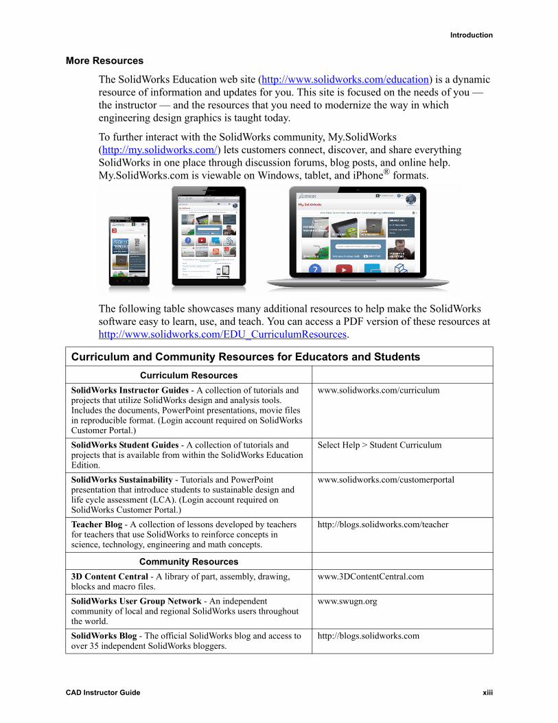
To further interact with the SolidWorks community, My.SolidWorks (http://my.solidworks.com/) lets customers connect, discover, and share everything SolidWorks in one place through discussion forums, blog posts, and online help. My.SolidWorks.com is viewable on Windows, tablet, and iPhone® formats.
The following table showcases many additional resources to help make the SolidWorks software easy to learn, use, and teach. You can access a PDF version of these resources at http://www.solidworks.com/EDU_CurriculumResources.
Curriculum and Community Resources for Educators and Students
Curriculum Resources
SolidWorks Instructor Guides - A collection of tutorials and projects that utilize SolidWorks design and analysis tools. Includes the documents, PowerPoint presentations, movie files in reproducible format. (Login account required on SolidWorks Customer Portal.)
www.solidworks.com/curriculum
SolidWorks Student Guides - A collection of tutorials and projects that is available from within the SolidWorks Education Edition.
Select Help > Student Curriculum
SolidWorks Sustainability - Tutorials and PowerPoint presentation that introduce students to sustainable design and life cycle assessment (LCA). (Login account required on SolidWorks Customer Portal.)
www.solidworks.com/customerportal
Teacher Blog - A collection of lessons developed by teachers for teachers that use SolidWorks to reinforce concepts in science, technology, engineering and math concepts.
http://blogs.solidworks.com/teacher
Community Resources
3D Content Central - A library of part, assembly, drawing, blocks and macro files.
www.3DContentCentral.com
SolidWorks User Group Network - An independent community of local and regional SolidWorks users throughout the world.
www.swugn.org
SolidWorks Blog - The official SolidWorks blog and access to over 35 independent SolidWorks bloggers.
http://blogs.solidworks.com
CAD Instructor Guide xiii
Introduction
Focused Product Development Applications
There are additional SolidWorks Education packages that can be purchased that offer students more focused product development applications. These include:
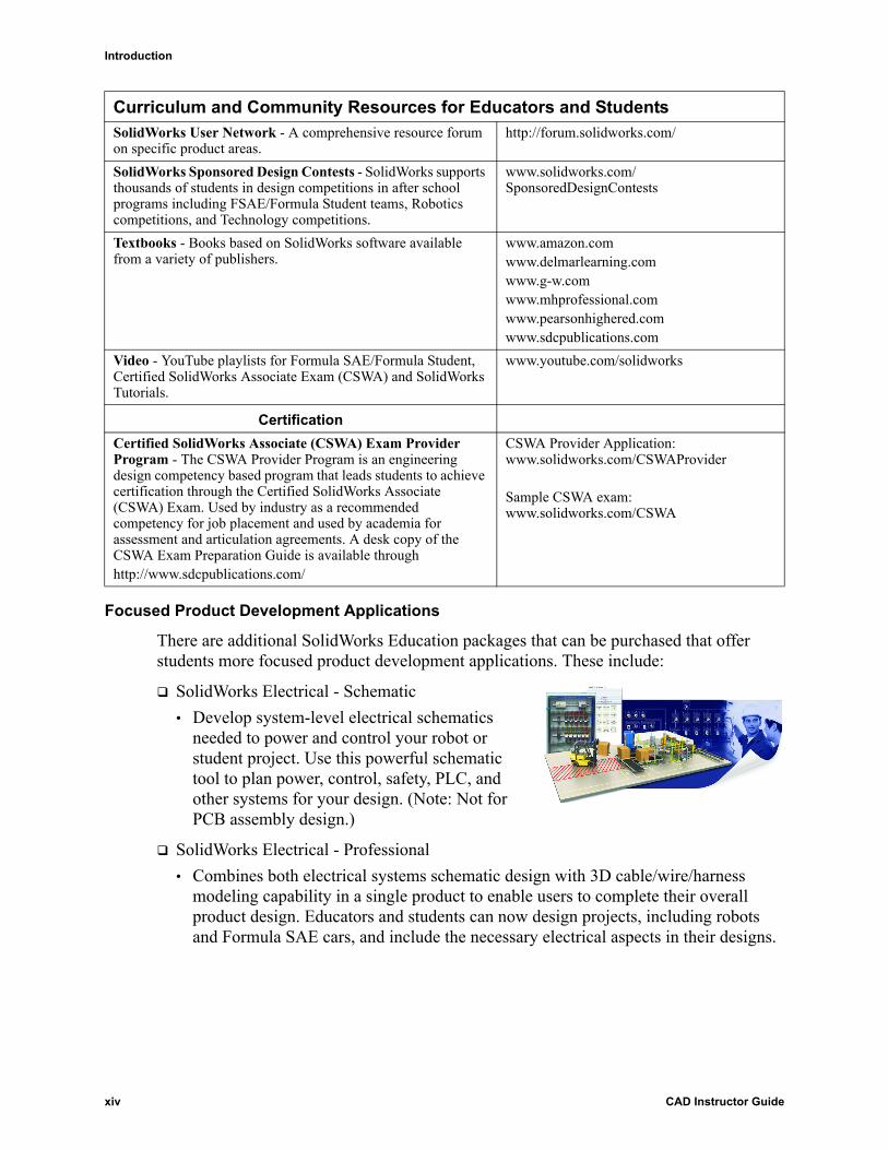
SolidWorks Electrical - Schematic
• Develop system-level electrical schematics needed to power and control your robot or student project. Use this powerful schematic tool to plan power, control, safety, PLC, and other systems for your design. (Note: Not for PCB assembly design.)
SolidWorks Electrical - Professional
• Combines both electrical systems schematic design with 3D cable/wire/harness modeling capability in a single product to enable users to complete their overall product design. Educators and students can now design projects, including robots and Formula SAE cars, and include the necessary electrical aspects in their designs.
SolidWorks User Network - A comprehensive resource forum on specific product areas.
http://forum.solidworks.com/
SolidWorks Sponsored Design Contests - SolidWorks supports thousands of students in design competitions in after school programs including FSAE/Formula Student teams, Robotics competitions, and Technology competitions.
www.solidworks.com/SponsoredDesignContests
Textbooks - Books based on SolidWorks software available from a variety of publishers.
www.amazon.comwww.delmarlearning.com www.g-w.com www.mhprofessional.comwww.pearsonhighered.comwww.sdcpublications.com
Video - YouTube playlists for Formula SAE/Formula Student, Certified SolidWorks Associate Exam (CSWA) and SolidWorks Tutorials.
www.youtube.com/solidworks
Certification
Certified SolidWorks Associate (CSWA) Exam Provider Program - The CSWA Provider Program is an engineering design competency based program that leads students to achieve certification through the Certified SolidWorks Associate (CSWA) Exam. Used by industry as a recommended competency for job placement and used by academia for assessment and articulation agreements. A desk copy of the CSWA Exam Preparation Guide is available through http://www.sdcpublications.com/
CSWA Provider Application: www.solidworks.com/CSWAProvider
Sample CSWA exam:www.solidworks.com/CSWA
Curriculum and Community Resources for Educators and Students
xiv CAD Instructor Guide
Introduction
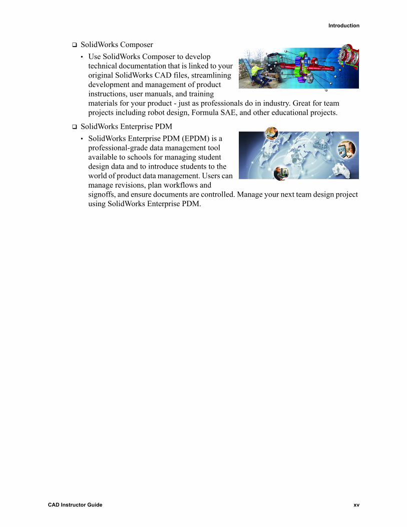
SolidWorks Composer
• Use SolidWorks Composer to develop technical documentation that is linked to your original SolidWorks CAD files, streamlining development and management of product instructions, user manuals, and training materials for your product - just as professionals do in industry. Great for team projects including robot design, Formula SAE, and other educational projects.
SolidWorks Enterprise PDM
• SolidWorks Enterprise PDM (EPDM) is a professional-grade data management tool available to schools for managing student design data and to introduce students to the world of product data management. Users can manage revisions, plan workflows and signoffs, and ensure documents are controlled. Manage your next team design project using SolidWorks Enterprise PDM.
CAD Instructor Guide xv

Introduction
xvi CAD Instructor Guide

1
Lesson 1: Using the Interface
Goals of This Lesson
Become familiar with the Microsoft Windows® interface.
Become familiar with the SolidWorks user interface.
Before Beginning This Lesson
Verify that Microsoft Windows is loaded and running on your classroom/lab computers.
Verify that the SolidWorks software is loaded and running on your classroom/lab computers in accordance with your SolidWorks license.
Load the lesson files from the Educator Resources link.
Outline of Lesson 1
Active Learning Exercise — Using the Interface
• Starting a Program
• Exiting a Program
• Opening an Existing File
• Saving a File
• Copying a File
• Resizing Windows
• SolidWorks Windows
• CommandManager
• Mouse Buttons
• Context-sensitive Shortcut Menus
• Getting Online Help
• Lesson Summary
Note: If your students are already experienced with the Microsoft Windows Graphical User Interface, you may wish to skip to the section of this lesson that familiarizes students with the SolidWorks user interface.
The CAD Instructor Guide provides additional examples, presentations, model files, and quizzes. Visit www.solidworks.com/customerportal for more.
CAD Instructor Guide 1
Lesson 1: Using the Interface
Competencies for Lesson 1
Students develop the following competencies in this lesson:
Engineering: Knowledge of an engineering design industry software application.
Technology: Understand file management, copy, save, starting and exiting programs.
Active Learning Exercise — Using the Interface
Start the SolidWorks application, open a file, save the file, save the file with a new name, and review the basic user interface.
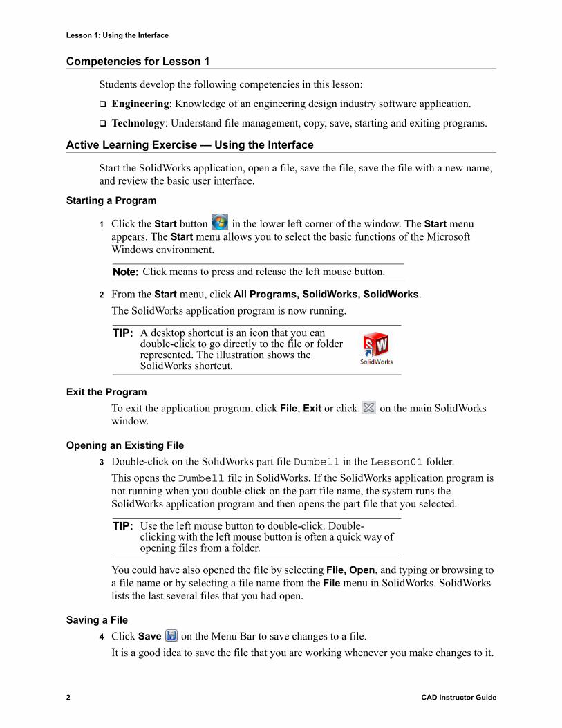
Starting a Program
1 Click the Start button in the lower left corner of the window. The Start menu appears. The Start menu allows you to select the basic functions of the Microsoft Windows environment.
2 From the Start menu, click All Programs, SolidWorks, SolidWorks.
The SolidWorks application program is now running.
Exit the Program
To exit the application program, click File, Exit or click on the main SolidWorks window.
Opening an Existing File
3 Double-click on the SolidWorks part file Dumbell in the Lesson01 folder.
This opens the Dumbell file in SolidWorks. If the SolidWorks application program is not running when you double-click on the part file name, the system runs the SolidWorks application program and then opens the part file that you selected.
You could have also opened the file by selecting File, Open, and typing or browsing to a file name or by selecting a file name from the File menu in SolidWorks. SolidWorks lists the last several files that you had open.
Saving a File
4 Click Save on the Menu Bar to save changes to a file.
It is a good idea to save the file that you are working whenever you make changes to it.
Note: Click means to press and release the left mouse button.
TIP: A desktop shortcut is an icon that you can double-click to go directly to the file or folder represented. The illustration shows the SolidWorks shortcut.
TIP: Use the left mouse button to double-click. Double-clicking with the left mouse button is often a quick way of opening files from a folder.
2 CAD Instructor Guide

Lesson 1: Using the Interface
Copying a File
Notice that Dumbell is not spelled correctly. It is supposed to have two “b’s”.
1 Click File, Save As to save a copy of the file with a new name.
The Save As window appears. This window shows you in which folder the file is currently located, the file name, and the file type.
2 In the File Name field change the name to Dumbbell and click Save.
A new file is created with the new name. The original file still exists. The new file is an exact copy of the file as it exists at the moment that it is copied.
Resizing Windows
SolidWorks, like many applications, uses windows to show your work. You can change the size of each window.
1 Move the cursor along the edge of a window until the shape of the cursor appears to be a two-headed arrow.
2 While the cursor still appears to be a two-headed arrow, hold down the left mouse button and drag the window to a different size.
3 When the window appears to be the size that you wish, release the mouse button.
Windows can have multiple panels. You can resize these panels relative to each other.
4 Move the cursor along the border between two panels until the cursor appears to be two parallel lines with perpendicular arrows.
5 While the cursor still appears to be two parallel lines with perpendicular arrows, hold down the left mouse button and drag the panel to a different size.
6 When the panel appears to be the size that you wish, release the mouse button.
SolidWorks Windows
SolidWorks windows have two panels. One panel provides non-graphic data. The other panel provides graphic representation of the part, assembly, or drawing.
The leftmost panel of the window contains the FeatureManager® design tree, PropertyManager and ConfigurationManager.
1 Click each of the tabs at the top of the left panel and see how the contents of the window changes.
CAD Instructor Guide 3

Lesson 1: Using the Interface
The rightmost panel is the graphics area, where you create and manipulate the part, assembly, or drawing.
2 Look at the graphics area. See how the dumbbell is represented. It appears shaded, in color and in an isometric view. These are some of the ways in which the model can be represented very realistically.
CommandManager
The CommandManager is a context-sensitive toolbar that dynamically updates based on the functions you want to access. By default, it displays tabs that are based on the document type. Use the CommandManager to access functions in a central location and to save space for the graphics area.
When you click a tab in the control area, the CommandManager updates to show those tools. For example, if you click Sketch in the control area, the sketch tools appear in the CommandManager. The convention for using the CommandManager is to write, “Click Sketch > Smart Dimension .” In this convention, Sketch is the CommandManager tab and Smart Dimension is the tooltip.
Mouse Buttons
Mouse buttons operate in the following ways:
Left – Selects menu items, entities in the graphics area, and objects in the FeatureManager design tree.
Right – Displays the context-sensitive shortcut menus.
Middle – Rotates, pans, and zooms the view of a part or an assembly, and pans in a drawing.
Model
Graphics area
Left panel displaying the FeatureManager design tree
control area
4 CAD Instructor Guide

Lesson 1: Using the Interface
Shortcut Menus
Shortcut menus give you access to a wide variety of tools and commands while you work in SolidWorks. When you move the pointer over geometry in the model, over items in the FeatureManager design tree, or over the SolidWorks window borders, right-clicking pops up a shortcut menu of commands that are appropriate for wherever you clicked.
You can access the "more commands menu" by selecting the double-down arrows in the menu. When you select the double-down arrows or pause the pointer over the double-down arrows, the shortcut menu expands to offer more menu items.
The shortcut menu provides an efficient way to work without continually moving the pointer to the main pull-down menus or the CommandManager.
Getting Online Help
If you have questions while you are using the SolidWorks software, you can find answers in several ways:
Click the flyout menu of Help options in the menu bar.
Click Help, SolidWorks Help.
While in a command, click Help in the dialog.
CAD Instructor Guide 5
Lesson 1: Using the Interface
Lesson 1 — 5 Minute Assessment — Answer Key
Name: _______________________________Class: _________ Date:_______________
Directions: Answer each question by writing the correct answer or answers in the space provided or circle the answer as directed.
1 How do you open the file from Windows Explorer?
Answer: Double-click on the file name.
2 How do you start the SolidWorks program?
Answer: Click , All Programs, SolidWorks, SolidWorks.
3 What is the quickest way to start the SolidWorks program?
Answer: Double-click the SolidWorks desktop shortcut (if one exists).
4 How do you copy a part within the SolidWorks program?
Answer: Click File, Save As and assign a new name.
6 CAD Instructor Guide

Lesson 1: Using the Interface
Lesson 1 — 5 Minute Assessment REPRODUCIBLE
Name: _______________________________Class: _________ Date:_______________
Directions: Answer each question by writing the correct answer or answers in the space provided or circle the answer as directed.
1 How do you open the file from Windows Explorer?
_____________________________________________________________________
2 How do you start the SolidWorks program?
_____________________________________________________________________
3 What is the quickest way to start the SolidWorks program?
_____________________________________________________________________
4 How do you copy a part within the SolidWorks program?
_____________________________________________________________________
CAD Instructor Guide 7
Lesson 1: Using the Interface
Lesson 1 Vocabulary Worksheet — Answer Key
Name: _______________________________Class: _________ Date:_______________
Fill in the blanks with the words that are defined by the clues.
1 Shortcuts for collections of frequently used commands: CommandManager tabs
2 Command to create a copy of a file with a new name: File, Save As
3 One of the areas that a window is divided into: panel
4 The graphic representation of a part, assembly, or drawing: model
5 Area of the screen that displays the work of a program: window
6 Icon that you can double-click to start a program: desktop shortcut
7 Action that quickly displays shortcut menus of frequently used or detailed commands: right-click
8 Command that updates your file with changes that you have made to it: File, Save
9 Action that quickly opens a part or program: double-click
10 The program that helps you create parts, assemblies, and drawings: SolidWorks
11 Panel of the SolidWorks window that displays a visual representation of your parts, assemblies, and drawings: graphics area
8 CAD Instructor Guide

Lesson 1: Using the Interface
Lesson 1 Vocabulary Worksheet REPRODUCIBLE
Name: _______________________________Class: _________ Date:_______________
Fill in the blanks with the words that are defined by the clues.
1 Shortcuts for collections of frequently used commands: ________________________
2 Command to create a copy of a file with a new name: __________________________
3 One of the areas that a window is divided into: _______________________________
4 The graphic representation of a part, assembly, or drawing: ______________________
5 Area of the screen that displays the work of a program: _________________________
6 Icon that you can double-click to start a program: _____________________________
7 Action that quickly displays shortcut menus of frequently used or detailed commands:
_____________________________________________________________________
8 Command that updates your file with changes that you have made to it: ____________
_____________________________________________________________________
9 Action that quickly opens a part or program: _________________________________
10 The program that helps you create parts, assemblies, and drawings: _______________
11 Panel of the SolidWorks window that displays a visual representation of your parts, assemblies, and drawings: ________________________________________________
CAD Instructor Guide 9
Lesson 1: Using the Interface
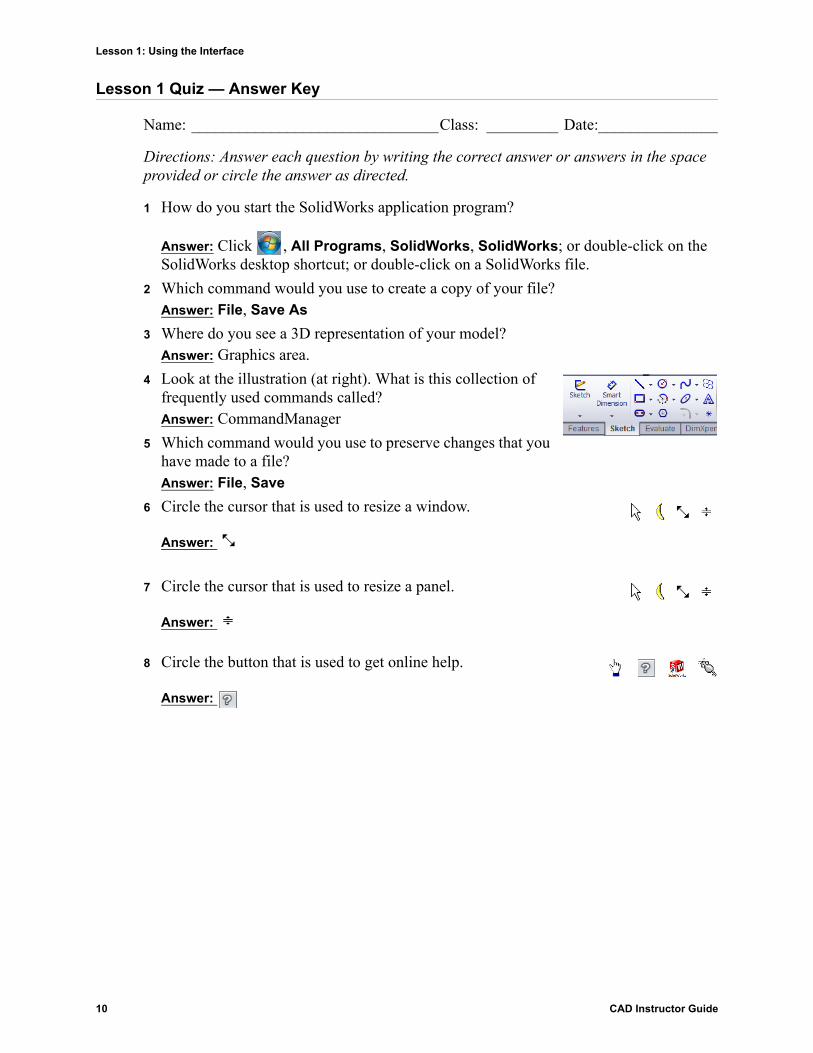
Lesson 1 Quiz — Answer Key
Name: _______________________________Class: _________ Date:_______________
Directions: Answer each question by writing the correct answer or answers in the space provided or circle the answer as directed.
1 How do you start the SolidWorks application program?
Answer: Click , All Programs, SolidWorks, SolidWorks; or double-click on the SolidWorks desktop shortcut; or double-click on a SolidWorks file.
2 Which command would you use to create a copy of your file?Answer: File, Save As
3 Where do you see a 3D representation of your model? Answer: Graphics area.
4 Look at the illustration (at right). What is this collection of frequently used commands called?Answer: CommandManager
5 Which command would you use to preserve changes that you have made to a file?Answer: File, Save
6 Circle the cursor that is used to resize a window.
Answer:
7 Circle the cursor that is used to resize a panel.
Answer:
8 Circle the button that is used to get online help.
Answer:
10 CAD Instructor Guide

Lesson 1: Using the Interface
Lesson 1 Quiz REPRODUCIBLE
Name: _______________________________Class: _________ Date:_______________
Directions: Answer each question by writing the correct answer or answers in the space provided or circle the answer as directed.
1 How do you start the SolidWorks application program?
_____________________________________________________________________
_____________________________________________________________________
2 Which command would you use to create a copy of your file? ____________________
3 Where do you see a 3D representation of your model? __________________________
4 Look at the illustration (at right). What is this collection of frequently used commands called?
5 Which command would you use to preserve changes that you have made to a file?
_____________________________________________________________________
6 Circle the cursor that is used to resize a window.
7 Circle the cursor that is used to resize a panel.
8 Circle the button that is used to get online help.
CAD Instructor Guide 11

Lesson 1: Using the Interface
Lesson Summary
The Start menu is where you go to start programs or find files.
There are shortcuts such as right-click and double-click that can save you work.
File, Save allows you to save updates to a file and File, Save As allows you to make a copy of a file.
You can change the size and location of windows as well as panels within windows.
The SolidWorks window has a graphics area that shows 3D representations of your models.
12 CAD Instructor Guide

Lesson 1: Using the Interface
Thumbnail Images of PowerPoint Slides
The following thumbnail images, arranged left to right, show the PowerPoint slides provided with this lesson.
1
3DS.
COM
© Da
ssau
lt Sy
stème
s | C
onfid
entia
l Info
rmati
on |
9/5/20
13 |
ref.:
3DS_
Docu
ment_
2012
3D
S.CO
M ©
Dass
ault
Systè
mes |
Con
fiden
tial I
nform
ation
| 9/5
/2013
| re
f.: 3D
S_Do
cume
nt_20
12 CAD Instructor Guide
Lesson 1 School’s Name
Teacher’s Name Date
3DS.
COM/
SOLI
DWOR
KS ©
Das
sault
Sys
tèmes
| Con
fiden
tial I
nform
ation
| 9/5
/2013
| re
f.: 3D
S_Do
cume
nt_20
12
2
Using the Interface
Use windows to view files. Use the mouse to select buttons, menus, and model elements. Run programs — like SolidWorks mechanical design software. Find, open, and work with files. Create, save, and copy files.
The interface is how you interact with the computer in the following ways:
3DS.
COM/
SOLI
DWOR
KS ©
Das
sault
Sys
tèmes
| Con
fiden
tial I
nform
ation
| 9/5
/2013
| re
f.: 3D
S_Do
cume
nt_20
12
3
Microsoft® Windows®
SolidWorks runs on the Microsoft Windows graphical user interface. Windows let you see the work of an application program. Panels are sub sections of windows. Illustration shows one window with two panels.
3DS.
COM/
SOLI
DWOR
KS ©
Das
sault
Sys
tèmes
| Con
fiden
tial I
nform
ation
| 9/5
/2013
| re
f.: 3D
S_Do
cume
nt_20
12
4
The mouse lets you move around the interface. The cursor is the pointer that shows you where the mouse is on the screen. Click the left mouse button to select commands, buttons, geometry, and other elements. Double-click the left mouse button to quickly open a file or folder. Click the right mouse button to access a shortcut menu of frequently used commands.
e
Using the Mouse
3DS.
COM/
SOLI
DWOR
KS ©
Das
sault
Sys
tèmes
| Con
fiden
tial I
nform
ation
| 9/5
/2013
| re
f.: 3D
S_Do
cume
nt_20
12
5
Running Programs
The quickest way to start a program is to double-click on a desktop shortcut. Some programs may not have desktop shortcuts. The Programs menu lists all of the application programs resident on the computer.
3DS.
COM/
SOLI
DWOR
KS ©
Das
sault
Sys
tèmes
| Con
fiden
tial I
nform
ation
| 9/5
/2013
| re
f.: 3D
S_Do
cume
nt_20
12
6
Exit a Program Select or click File, Exit to end a program. If the file has unsaved changes, you have the chance to save the them before exiting.
CAD Instructor Guide 13

Lesson 1: Using the Interface
3DS.
COM/
SOLI
DWOR
KS ©
Das
sault
Sys
tèmes
| Con
fiden
tial I
nform
ation
| 9/5
/2013
| re
f.: 3D
S_Do
cume
nt_20
12
7
Opening a File The quickest way to open a file is to double-click on it. The File menu displays your most recently used files.
3DS.
COM/
SOLI
DWOR
KS ©
Das
sault
Sys
tèmes
| Con
fiden
tial I
nform
ation
| 9/5
/2013
| re
f.: 3D
S_Do
cume
nt_20
12
8
Saving and Copying Files Saving a file preserves the changes that you have made to it. Use File, Save As to copy a file. File, Save As creates an exact duplicate of the file as it existed at the moment that you copied it.
3DS.
COM/
SOLI
DWOR
KS ©
Das
sault
Sys
tèmes
| Con
fiden
tial I
nform
ation
| 9/5
/2013
| re
f.: 3D
S_Do
cume
nt_20
12
9
Resizing Windows Allows you to customize the appearance of your screen. View multiple files at the same time. Use to change the size of a window. Use to change the size of panels within a window.
3DS.
COM/
SOLI
DWOR
KS ©
Das
sault
Sys
tèmes
| Con
fiden
tial I
nform
ation
| 9/5
/2013
| re
f.: 3D
S_Do
cume
nt_20
12
10
Using the SolidWorks Interface SolidWorks windows display graphic and non-graphic model data. CommandManager tabs display frequently used commands.
3DS.
COM/
SOLI
DWOR
KS ©
Das
sault
Sys
tèmes
| Con
fiden
tial I
nform
ation
| 9/5
/2013
| re
f.: 3D
S_Do
cume
nt_20
12
11
Left Side of SolidWorks Window FeatureManager® design tree
Property Manager
Configuration Manager
3DS.
COM/
SOLI
DWOR
KS ©
Das
sault
Sys
tèmes
| Con
fiden
tial I
nform
ation
| 9/5
/2013
| re
f.: 3D
S_Do
cume
nt_20
12
12
Right Side of SolidWorks Window
SolidWorks Resources The Task Pane
Design Library
14 CAD Instructor Guide

Lesson 1: Using the Interface
3DS.
COM/
SOLI
DWOR
KS ©
Das
sault
Sys
tèmes
| Con
fiden
tial I
nform
ation
| 9/5
/2013
| re
f.: 3D
S_Do
cume
nt_20
12
13
Right Side of SolidWorks Window
Toolbox The Task Pane
File Explorer
3DS.
COM/
SOLI
DWOR
KS ©
Das
sault
Sys
tèmes
| Con
fiden
tial I
nform
ation
| 9/5
/2013
| re
f.: 3D
S_Do
cume
nt_20
12
14
CommandManager
CommandManager tabs include buttons for frequently used commands. The visible tabs change based on the open document type: part, assembly, or drawing. The CommandManager is displayed at the top of the window.
3DS.
COM/
SOLI
DWOR
KS ©
Das
sault
Sys
tèmes
| Con
fiden
tial I
nform
ation
| 9/5
/2013
| re
f.: 3D
S_Do
cume
nt_20
12
15
To view comprehensive online help:
Getting Help
Click . Select Help, SolidWorks Help. Help displays in a separate window.
CAD Instructor Guide 15

Lesson 1: Using the Interface
16 CAD Instructor Guide

2
Lesson 2: Basic Functionality
Goals of This Lesson
Understand the basic functionality of the SolidWorks software.
Create the following part:
Before Beginning This Lesson
Complete Lesson 1: Using the Interface.
Access a wide range of free, informative resources - full video tutorials, PDF guides, project files, and demo clips - designed to help you become a top SolidWorks user. Visithttp://www.solidworks.com/tutorials.
CAD Instructor Guide 17

Lesson 2: Basic Functionality
Review of Lesson 1: Using the Interface
The interface is how you interact with the computer in the following ways:
Use windows to view files.
Use the mouse to select buttons, menus, and model elements.
Run programs — like SolidWorks mechanical design software.
Find, open, and work with files.
Create, save, and copy files.
SolidWorks runs on the Microsoft Windows graphical user interface.
The mouse lets you move around the interface.
The quickest way to open a file is to double-click on it.
Saving a file preserves the changes that you have made to it.
SolidWorks windows display graphic and non-graphic model data.
CommandManager tabs display frequently used commands.
18 CAD Instructor Guide

Lesson 2: Basic Functionality
Outline of Lesson 2
In Class Discussion — The SolidWorks Model
Active Learning Exercise — Creating a Basic Part
• Create a New Part Document
• Overview of the SolidWorks Window
• Sketch a Rectangle
• Add Dimensions
• Changing the Dimension Values
• Extrude the Base Feature
• View Display
• Save the Part
• Round the Corners of the Part
• Hollow Out the Part
• Extruded Cut Feature
• Open a Sketch
• Sketch the Circle
• Dimension the Circle
• Extrude the Sketch
• Rotate the View
• Save the Part
In Class Discussion — Describing the Base Feature
Exercises and Projects — Designing a Switch Plate
More to Explore — Modifying a Part
Lesson Summary
Competencies for Lesson 2
Students develop the following competencies in this lesson:
Engineering: Develop a 3D part based on a selected plane, dimensions, and features. Apply the design process to develop the box or switch plate out of cardboard or other material. Develop manual sketching techniques by drawing the switch plate.
Technology: Apply a windows based graphical user interface.
Math: Understand units of measurement, adding and subtracting material, perpendicularity, and the x-y-z coordinate system.
CAD Instructor Guide 19

Lesson 2: Basic Functionality
In Class Discussion — The SolidWorks Model
SolidWorks is design automation software. In SolidWorks, you sketch ideas and experiment with different designs to create 3D models. SolidWorks is used by students, designers, engineers, and other professionals to produce simple and complex parts, assemblies, and drawings.
The SolidWorks model is made up of:
Parts
Assemblies
Drawings
A part is a single 3D object made up of features. A part can become a component in an assembly, and it can be represented in 2D in a drawing. Examples of parts are bolt, pin, plate, and so on. The extension for a SolidWorks part file name is .SLDPRT. Features are the shapes and operations that construct the part. The Base feature is the first feature that is created.The Base feature is the foundation of the part.
An assembly is a document in which parts, features, and other assemblies (sub-assemblies) are mated together. The parts and sub-assemblies exist in documents separate from the assembly. For example, in an assembly, a piston can be mated to other parts, such as a connecting rod or cylinder. This new assembly can then be used as a sub-assembly in an assembly of an engine. The extension for a SolidWorks assembly file name is .SLDASM.
A drawing is a 2D representation of a 3D part or assembly. The extension for a SolidWorks drawing file name is .SLDDRW.
20 CAD Instructor Guide

Lesson 2: Basic Functionality
Active Learning Exercises — Creating a Basic Part
Use SolidWorks to create the box shown at the right.
The step-by-step instructions are given below.
Create a New Part Document
1 Create a new part. Click
New on the Menu Bar.
The New SolidWorks Document dialog box appears.
2 Click the Tutorial tab.
3 Select the Part icon.
4 Click OK.
A new part document window appears.
Setting Units
The units for a document can be set by clicking Tools, Options and then under the Document Properties tab, selecting units from the menu on the left. In the status bar, units can also be changed by clicking Unit System and then selecting the new unit system.
Base Feature
The Base feature requires:
Sketch plane – Front
Sketch profile – 2D Rectangle
Feature type – Extruded boss feature
Open a Sketch
1 Click to select the Front plane in the FeatureManager design tree.
2 Open a 2D sketch. Click Sketch > Sketch .
Confirmation Corner
When many SolidWorks commands are active, a symbol or a set of symbols appears in the upper right corner of the graphics area. This area is called the Confirmation Corner.
CAD Instructor Guide 21
Lesson 2: Basic Functionality
Sketch Indicator
When a sketch is active, or open, a symbol appears in the confirmation corner that looks like the Sketch tool. It provides a visual reminder that you are active in a sketch. Clicking this symbol exits the sketch saving your changes. Clicking the red X exits the sketch discarding your changes.
When other commands are active, the confirmation corner displays two symbols: a check mark and an X. The check mark executes the current command. The X cancels the command.
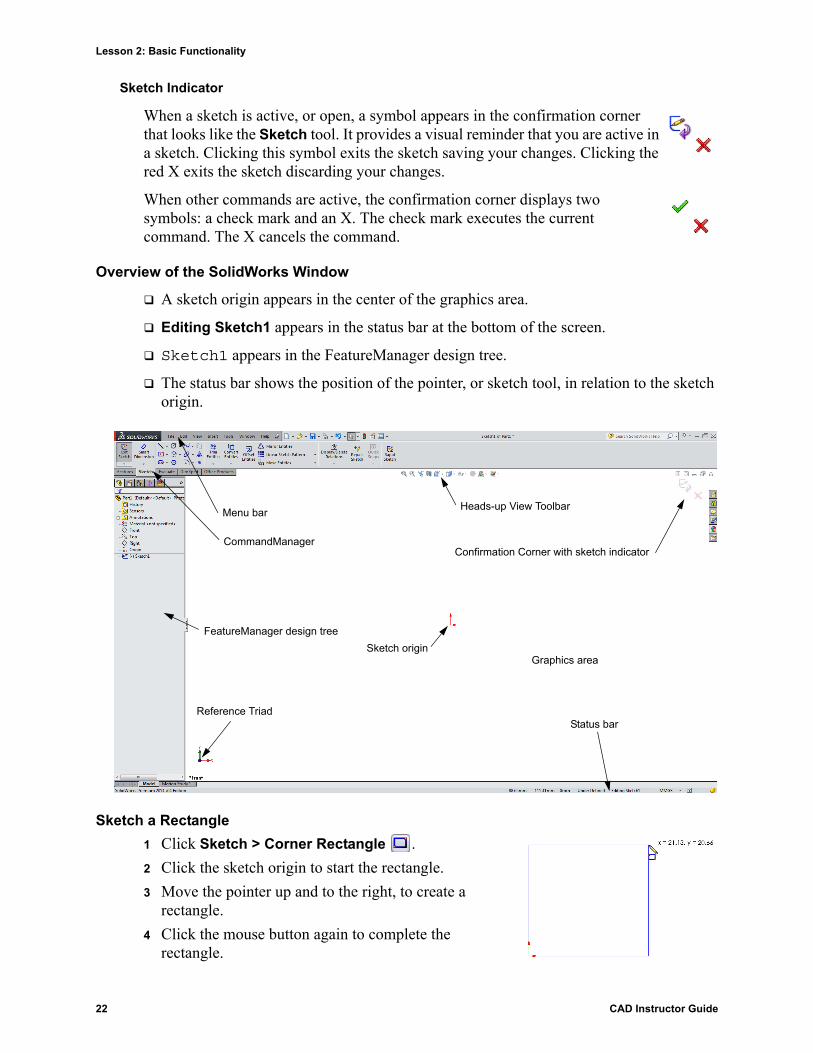
Overview of the SolidWorks Window
A sketch origin appears in the center of the graphics area.
Editing Sketch1 appears in the status bar at the bottom of the screen.
Sketch1 appears in the FeatureManager design tree.
The status bar shows the position of the pointer, or sketch tool, in relation to the sketch origin.
Sketch a Rectangle
1 Click Sketch > Corner Rectangle .
2 Click the sketch origin to start the rectangle.
3 Move the pointer up and to the right, to create a rectangle.
4 Click the mouse button again to complete the rectangle.
Status bar
Graphics areaSketch origin
Menu bar
FeatureManager design tree
Confirmation Corner with sketch indicator
Reference Triad
CommandManager
Heads-up View Toolbar
22 CAD Instructor Guide

Lesson 2: Basic Functionality
Add Dimensions
1 Click Sketch > Smart Dimension .
The pointer shape changes to .
2 Click the top line of the rectangle.
3 Click the dimension text location above the top line.
The Modify dialog box is displayed.
4 Enter 100. Click or press Enter.
5 Click the right edge of the rectangle.
6 Click the dimension text location. Enter 65. Click .
The top segment and the remaining vertices are displayed in black. The status bar in the lower-right corner of the window indicates that the sketch is fully defined.
Changing the Dimension Values
The new dimensions for the box are 100mm x 60mm. Change the dimensions.
1 Double-click 65.
The Modify dialog box appears.
2 Enter 60 in the Modify dialog box.
3 Click .
Extrude the Base Feature.
The first feature in any part is called the Base Feature. In this exercise, the base feature is created by extruding the sketched rectangle.
1 Click Features > Extruded Boss/Base
The Boss-Extrude PropertyManager appears. The view of the sketch changes to trimetric.
CAD Instructor Guide 23