Edition 2.0 2007-08 INTERNATIONAL STANDARD NORME ...
19
IEC 60364-4-44 Edition 2.0 2007-08 INTERNATIONAL STANDARD NORME INTERNATIONALE Low-voltage electrical installations – Part 4-44: Protection for safety – Protection against voltage disturbances and electromagnetic disturbances Installations électriques à basse tension – Partie 4-44: Protection pour assurer la sécurité – Protection contre les perturbations de tension et les perturbations électromagnétiques IEC 60364-4-44:2007 This preview is downloaded from www.sis.se. Buy the entire standard via https://www.sis.se/std-568981 Copyright © IEC, 2007, Geneva, Switzerland. All rights reserved. Sold by SIS under license from IEC and SEK. No part of this document may be copied, reproduced or distributed in any form without the prior written consent of the IEC.
Transcript of Edition 2.0 2007-08 INTERNATIONAL STANDARD NORME ...
IEC 60364-4-44Edition 2.0 2007-08
INTERNATIONAL STANDARD NORME INTERNATIONALE
Low-voltage electrical installations – Part 4-44: Protection for safety – Protection against voltage disturbances and electromagnetic disturbances Installations électriques à basse tension – Partie 4-44: Protection pour assurer la sécurité – Protection contre les perturbations de tension et les perturbations électromagnétiques
IEC
603
64-4
-44:
2007
This preview is downloaded from www.sis.se. Buy the entire standard via https://www.sis.se/std-568981
Copyright © IEC, 2007, Geneva, Switzerland. All rights reserved. Sold by SIS under license from IEC and SEK.No part of this document may be copied, reproduced or distributed in any form without the prior written consent of the IEC.

THIS PUBLICATION IS COPYRIGHT PROTECTED Copyright © 2007 IEC, Geneva, Switzerland All rights reserved. Unless otherwise specified, no part of this publication may be reproduced or utilized in any form or by any means, electronic or mechanical, including photocopying and microfilm, without permission in writing from either IEC or IEC's member National Committee in the country of the requester. If you have any questions about IEC copyright or have an enquiry about obtaining additional rights to this publication, please contact the address below or your local IEC member National Committee for further information. Droits de reproduction réservés. Sauf indication contraire, aucune partie de cette publication ne peut être reproduite ni utilisée sous quelque forme que ce soit et par aucun procédé, électronique ou mécanique, y compris la photocopie et les microfilms, sans l'accord écrit de la CEI ou du Comité national de la CEI du pays du demandeur. Si vous avez des questions sur le copyright de la CEI ou si vous désirez obtenir des droits supplémentaires sur cette publication, utilisez les coordonnées ci-après ou contactez le Comité national de la CEI de votre pays de résidence.
IEC Central Office 3, rue de Varembé CH-1211 Geneva 20 Switzerland Email: [email protected] Web: www.iec.ch
About the IEC The International Electrotechnical Commission (IEC) is the leading global organization that prepares and publishes International Standards for all electrical, electronic and related technologies.
About IEC publications The technical content of IEC publications is kept under constant review by the IEC. Please make sure that you have the latest edition, a corrigenda or an amendment might have been published. Catalogue of IEC publications: www.iec.ch/searchpub
The IEC on-line Catalogue enables you to search by a variety of criteria (reference number, text, technical committee,…). It also gives information on projects, withdrawn and replaced publications. IEC Just Published: www.iec.ch/online_news/justpub
Stay up to date on all new IEC publications. Just Published details twice a month all new publications released. Available on-line and also by email. Electropedia: www.electropedia.org
The world's leading online dictionary of electronic and electrical terms containing more than 20 000 terms and definitions in English and French, with equivalent terms in additional languages. Also known as the International Electrotechnical Vocabulary online. Customer Service Centre: www.iec.ch/webstore/custserv
If you wish to give us your feedback on this publication or need further assistance, please visit the Customer Service Centre FAQ or contact us: Email: [email protected] Tel.: +41 22 919 02 11 Fax: +41 22 919 03 00
A propos de la CEI La Commission Electrotechnique Internationale (CEI) est la première organisation mondiale qui élabore et publie des normes internationales pour tout ce qui a trait à l'électricité, à l'électronique et aux technologies apparentées.
A propos des publications CEI Le contenu technique des publications de la CEI est constamment revu. Veuillez vous assurer que vous possédez l’édition la plus récente, un corrigendum ou amendement peut avoir été publié. Catalogue des publications de la CEI: www.iec.ch/searchpub/cur_fut-f.htm
Le Catalogue en-ligne de la CEI vous permet d’effectuer des recherches en utilisant différents critères (numéro de référence, texte, comité d’études,…). Il donne aussi des informations sur les projets et les publications retirées ou remplacées. Just Published CEI: www.iec.ch/online_news/justpub
Restez informé sur les nouvelles publications de la CEI. Just Published détaille deux fois par mois les nouvelles publications parues. Disponible en-ligne et aussi par email. Electropedia: www.electropedia.org
Le premier dictionnaire en ligne au monde de termes électroniques et électriques. Il contient plus de 20 000 termes et définitions en anglais et en français, ainsi que les termes équivalents dans les langues additionnelles. Egalement appelé Vocabulaire Electrotechnique International en ligne. Service Clients: www.iec.ch/webstore/custserv/custserv_entry-f.htm
Si vous désirez nous donner des commentaires sur cette publication ou si vous avez des questions, visitez le FAQ du Service clients ou contactez-nous: Email: [email protected] Tél.: +41 22 919 02 11 Fax: +41 22 919 03 00
This preview is downloaded from www.sis.se. Buy the entire standard via https://www.sis.se/std-568981
Copyright © IEC, 2007, Geneva, Switzerland. All rights reserved. Sold by SIS under license from IEC and SEK.No part of this document may be copied, reproduced or distributed in any form without the prior written consent of the IEC.

IEC 60364-4-44Edition 2.0 2007-08
INTERNATIONAL STANDARD NORME INTERNATIONALE
Low-voltage electrical installations – Part 4-44: Protection for safety – Protection against voltage disturbances and electromagnetic disturbances Installations électriques à basse tension – Partie 4-44: Protection pour assurer la sécurité – Protection contre les perturbations de tension et les perturbations électromagnétiques
INTERNATIONAL ELECTROTECHNICAL COMMISSION
COMMISSION ELECTROTECHNIQUE INTERNATIONALE XAICS 91.140.50
PRICE CODECODE PRIX
ISBN 2-8318-9261-9
This preview is downloaded from www.sis.se. Buy the entire standard via https://www.sis.se/std-568981
Copyright © IEC, 2007, Geneva, Switzerland. All rights reserved. Sold by SIS under license from IEC and SEK.No part of this document may be copied, reproduced or distributed in any form without the prior written consent of the IEC.

– 2 – 60364-4-44 © IEC:2007
CONTENTS
FOREWORD...........................................................................................................................5 INTRODUCTION.....................................................................................................................7
440.1 Scope ...................................................................................................................8 440.2 Normative references............................................................................................8
441 (Vacant) .........................................................................................................................9 442 Protection of low-voltage installations against temporary overvoltages due to earth
faults in the high-voltage system and due to faults in the low-voltage system ..................9 442.1 Scope and object ..................................................................................................9
442.1.1 General ...................................................................................................9 442.1.2 Symbols ................................................................................................10
442.2 Overvoltages in LV-systems during a high-voltage earth fault .............................. 11 442.2.1 Magnitude and duration of power frequency fault-voltage ....................... 12 442.2.2 Magnitude and duration of power frequency stress-voltages................... 13 442.2.3 Requirements for calculation of limits .................................................... 14
442.3 Power frequency stress voltage in case of loss of the neutral conductor in a TN and TT system ..............................................................................................14
442.4 Power frequency stress voltage in the event of an earth fault in an IT system with distributed neutral ........................................................................................14
442.5 Power frequency stress voltage in the event of short-circuit between a line conductor and the neutral conductor ................................................................... 14
443 Protection against overvoltages of atmospheric origin or due to switching ..................... 14 443.1 General ..............................................................................................................14 443.2 Classification of impulse withstand voltages (overvoltage categories) .................. 15
443.2.1 Purpose of classification of impulse withstand voltages (overvoltage categories) ........................................................................15
443.2.2 Relationship between impulse withstand voltages of equipment and overvoltage categories ..........................................................................15
443.3 Arrangements for overvoltage control ..................................................................16 443.3.1 Inherent overvoltage control .................................................................. 16 443.3.2 Protective overvoltage control................................................................16
443.4 Required impulse withstand voltage of equipment................................................18 444 Measures against electromagnetic influences ............................................................... 18
444.1 General ..............................................................................................................18 444.2 (void) ..................................................................................................................19 444.3 Definitions ..........................................................................................................19 444.4 Mitigation of Electromagnetic Interference (EMI) ................................................. 20
444.4.1 Sources of EMI......................................................................................20 444.4.2 Measures to reduce EMI........................................................................21 444.4.3 TN-system ............................................................................................22 444.4.4 TT system .............................................................................................26 444.4.5 IT system ..............................................................................................27 444.4.6 Multiple-source supply...........................................................................28 444.4.7 Transfer of supply ................................................................................. 31 444.4.8 Services entering a building...................................................................33 444.4.9 Separate buildings.................................................................................34 444.4.10 Inside buildings .....................................................................................34 444.4.11 Protective devices ................................................................................. 36
This preview is downloaded from www.sis.se. Buy the entire standard via https://www.sis.se/std-568981
Copyright © IEC, 2007, Geneva, Switzerland. All rights reserved. Sold by SIS under license from IEC and SEK.No part of this document may be copied, reproduced or distributed in any form without the prior written consent of the IEC.

60364-4-44 © IEC:2007 – 3 –
444.4.12 Signal cables.........................................................................................36 444.5 Earthing and equipotential bonding...................................................................... 36
444.5.1 Interconnection of earth electrodes ........................................................36 444.5.2 Interconnection of incoming networks and earthing arrangements .......... 37 444.5.3 Different structures for the network of equipotential conductors and
earthing conductors ...............................................................................37 444.5.4 Equipotential bonding networks in buildings with several floors .............. 39 444.5.5 Functional earthing conductor................................................................ 40 444.5.6 Commercial or industrial buildings containing significant amounts
of information technology equipment......................................................41 444.5.7 Earthing arrangements and equipotential bonding of information
technology installations for functional purposes ..................................... 41 444.6 Segregation of circuits ........................................................................................42
444.6.1 General .................................................................................................42 444.6.2 Design guidelines ..................................................................................42 444.6.3 Installation guidelines ............................................................................43
444.7 Cable management systems ...............................................................................44 444.7.1 General .................................................................................................44 444.7.2 Design guidelines ..................................................................................44 444.7.3 Installation guidelines ............................................................................45
445 Protection against undervoltage ...................................................................................47 445.1 General requirements .........................................................................................47
Annex A (informative) Explanatory notes concerning 442.1 and 442.2................................... 48 Annex B (informative) Guidance for overvoltage control by SPDs applied to overhead lines...................................................................................................................................... 50 Annex C (normative) Determination of the conventional length, d ......................................... 52 Bibliography .......................................................................................................................... 54 Figure 44.A1 – Representative schematic sketch for possible connections to earth in substation and LV-Installation and occurring overvoltages in case of faults ............................ 11 Figure 44.A2 – Tolerable fault-voltage due to an earth-fault in the HV system ........................ 13 Figure 44.R1 − By-pass conductor for screen reinforcement to provide a common equipotential bonding system ................................................................................................21 Figure 44.R2 − Example of a substitute or by-pass equipotential bonding conductor in a TT-system............................................................................................................................. 22 Figure 44.R3A − Avoidance of neutral conductor currents in a bonded structure by using the TN-S system from the origin of the public supply up to and including the final circuit within a building .......................................................................................................... 23 Figure 44.R3B − Avoidance of neutral conductor currents in a bonded structure by using a TN-S system downstream of a consumer’s private supply transformer ................................ 24 Figure 44.R4 − TN-C-S system within an existing building installation .................................... 25 Figure 44.R5 – TT system within a building installation ..........................................................26 Figure 44.R6 – IT system within a building installation ...........................................................27 Figure 44.R7A – TN multiple-source power supply with a non-suitable multiple connection between PEN and earth .......................................................................................28 Figure 44.R7B – TN multiple source power supplies to an installation with connection to earth of the star points at one and the same point ................................................................. 29
This preview is downloaded from www.sis.se. Buy the entire standard via https://www.sis.se/std-568981
Copyright © IEC, 2007, Geneva, Switzerland. All rights reserved. Sold by SIS under license from IEC and SEK.No part of this document may be copied, reproduced or distributed in any form without the prior written consent of the IEC.

– 4 – 60364-4-44 © IEC:2007
Figure 44.R8 – TT multiple-source power supplies to an installation with connection to earth of the star points at one and the same point ................................................................. 30 Figure 44.R9A − Three-phase alternative power supply with a 4-pole switch .......................... 31 Figure 44.R9B – Neutral current flow in a three-phase alternative power supply with an unsuitable 3-pole switch ........................................................................................................ 32 Figure 44.R9C − Single-phase alternative power supply with 2-pole switch............................. 33 Figure 44.R10 − Armoured cables and metal pipes entering the buildings (examples) ............ 34 Figure 44.R11 − Illustration of measures in an existing building ............................................. 35 Figure 44.R12 – Interconnected earth electrodes...................................................................36 Figure 44.R13 – Examples of protective conductors in star network ....................................... 37 Figure 44.R14 – Example of multiple meshed bonding star network ....................................... 38 Figure 44.R15 – Example of a common meshed bonding star network ................................... 39 Figure 44.R16 – Example of equipotential bonding networks in structures without lightning protection systems ..................................................................................................40 Figure 44.R17A − Separation between power and information technology cables for cable route lengths ≤ 35 m ....................................................................................................43 Figure 44.R17B − Separation between power and information technology cables for cable route lengths > 35 m .................................................................................................... 43 Figure 44.R18 – Separation of cables in wiring systems......................................................... 44 Figure 44.R19 – Cable arrangements in metal cable-trays ..................................................... 45 Figure 44.R20 – Continuity of metallic system components ....................................................46 Figure 44.R21 – Location of cables inside metallic construction elements .............................. 46 Figure 44.R22 – Connection of metallic sections....................................................................47 Figure 44.Q – Examples of how to apply d1, d2 and d3 for the determination of d ................... 53 Table 44.A1 – Power frequency stress voltages and power frequency fault voltage in the low voltage system ................................................................................................................ 12 Table 44.A2 – Permissible power frequency stress-voltage ....................................................13 Table 44.B – Required rated impulse withstand voltage of equipment .................................... 18 Table B.1 – Different possibilities for IT systems....................................................................51
This preview is downloaded from www.sis.se. Buy the entire standard via https://www.sis.se/std-568981
Copyright © IEC, 2007, Geneva, Switzerland. All rights reserved. Sold by SIS under license from IEC and SEK.No part of this document may be copied, reproduced or distributed in any form without the prior written consent of the IEC.

60364-4-44 © IEC:2007 – 5 –
INTERNATIONAL ELECTROTECHNICAL COMMISSION _______________
LOW-VOLTAGE ELECTRICAL INSTALLATIONS –
Part 4-44: Protection for safety –
Protection against voltage disturbances and electromagnetic disturbances
FOREWORD
1) The International Electrotechnical Commission (IEC) is a worldwide organization for standardization comprising all national electrotechnical committees (IEC National Committees). The object of IEC is to promote international co-operation on all questions concerning standardization in the electrical and electronic fields. To this end and in addition to other activities, IEC publishes International Standards, Technical Specifications, Technical Reports, Publicly Available Specifications (PAS) and Guides (hereafter referred to as “IEC Publication(s)”). Their preparation is entrusted to technical committees; any IEC National Committee interested in the subject dealt with may participate in this preparatory work. International, governmental and non-governmental organizations liaising with the IEC also participate in this preparation. IEC collaborates closely with the International Organization for Standardization (ISO) in accordance with conditions determined by agreement between the two organizations.
2) The formal decisions or agreements of IEC on technical matters express, as nearly as possible, an international consensus of opinion on the relevant subjects since each technical committee has representation from all interested IEC National Committees.
3) IEC Publications have the form of recommendations for international use and are accepted by IEC National Committees in that sense. While all reasonable efforts are made to ensure that the technical content of IEC Publications is accurate, IEC cannot be held responsible for the way in which they are used or for any misinterpretation by any end user.
4) In order to promote international uniformity, IEC National Committees undertake to apply IEC Publications transparently to the maximum extent possible in their national and regional publications. Any divergence between any IEC Publication and the corresponding national or regional publication shall be clearly indicated in the latter.
5) IEC provides no marking procedure to indicate its approval and cannot be rendered responsible for any equipment declared to be in conformity with an IEC Publication.
6) All users should ensure that they have the latest edition of this publication.
7) No liability shall attach to IEC or its directors, employees, servants or agents including individual experts and members of its technical committees and IEC National Committees for any personal injury, property damage or other damage of any nature whatsoever, whether direct or indirect, or for costs (including legal fees) and expenses arising out of the publication, use of, or reliance upon, this IEC Publication or any other IEC Publications.
8) Attention is drawn to the Normative references cited in this publication. Use of the referenced publications is indispensable for the correct application of this publication.
9) Attention is drawn to the possibility that some of the elements of this IEC Publication may be the subject of patent rights. IEC shall not be held responsible for identifying any or all such patent rights.
International Standard IEC 60364-4-44 has been prepared by IEC technical committee 64: Electrical installations and protection against electric shock.
This second edition of IEC 60364-4-44 cancels and replaces the first edition published in 2001, amendment 1 (2003) and amendment 2 (2006).
The document 64/1600/FDIS, circulated to the National Committees as Amendment 3, led to the publication of the new edition.
This preview is downloaded from www.sis.se. Buy the entire standard via https://www.sis.se/std-568981
Copyright © IEC, 2007, Geneva, Switzerland. All rights reserved. Sold by SIS under license from IEC and SEK.No part of this document may be copied, reproduced or distributed in any form without the prior written consent of the IEC.
– 6 – 60364-4-44 © IEC:2007
The text of this standard is based on the first edition, its Amendment 1, Amendment 2 and the following documents:
FDIS Report on voting
64/1600/FDIS 64/1609/RVD
Full information on the voting for the approval of this standard can be found in the report on voting indicated in the above table.
This publication has been drafted in accordance with the ISO/IEC Directives, Part 2.
A list of all the parts in the IEC 60364 series, under the general title Low-voltage electrical installations, can be found on the IEC website.
Future standards in this series will carry the new general title as cited above. Titles of existing standards in this series will be updated at the time of the next edition.
The committee has decided that the contents of this publication will remain unchanged until the maintenance result date indicated on the IEC web site under "http://webstore.iec.ch" in the data related to the specific publication. At this date, the publication will be
• reconfirmed, • withdrawn, • replaced by a revised edition, or • amended.
This preview is downloaded from www.sis.se. Buy the entire standard via https://www.sis.se/std-568981
Copyright © IEC, 2007, Geneva, Switzerland. All rights reserved. Sold by SIS under license from IEC and SEK.No part of this document may be copied, reproduced or distributed in any form without the prior written consent of the IEC.

60364-4-44 © IEC:2007 – 7 –
INTRODUCTION
Part 4-44 of IEC 60364 covers the protection of electrical installations and measures against voltage disturbances and electromagnetic disturbances.
The requirements are arranged into four clauses as follows:
Clause 442 Protection of low-voltage installations against temporary overvoltages due to earth faults in the high-voltage system and due to faults in the low-voltage system
Clause 443 Protection against overvoltages of atmospheric origin or due to switching Clause 444 Measures against electromagnetic influences Clause 445 Protection against undervoltage
This preview is downloaded from www.sis.se. Buy the entire standard via https://www.sis.se/std-568981
Copyright © IEC, 2007, Geneva, Switzerland. All rights reserved. Sold by SIS under license from IEC and SEK.No part of this document may be copied, reproduced or distributed in any form without the prior written consent of the IEC.
– 8 – 60364-4-44 © IEC:2007
LOW-VOLTAGE ELECTRICAL INSTALLATIONS –
Part 4-44: Protection for safety – Protection against voltage disturbances and
electromagnetic disturbances
440.1 Scope
The rules of this Part of IEC 60364 are intended to provide requirements for the safety of electrical installations in the event of voltage disturbances and electromagnetic disturbances generated for different specified reasons.
The rules of this part are not intended to apply to systems for distribution of energy to the public, or power generation and transmission for such systems (see the scope of IEC 60364-1) although such disturbances may be conducted into or between electrical installations via these supply systems.
440.2 Normative references
The following referenced documents are indispensable for the application of this document. For dated references, only the edition cited applies. For undated references, the latest edition of the referenced document (including any amendments) applies.
IEC 60038:1983, IEC standard voltages
IEC 60050-604:1987, International Electrotechnical Vocabulary – Chapter 604: Generation, transmission and distribution of electricity – Operation
IEC 60364-1, Low-voltage electrical installations – Part 1: Fundamental principles, assessment of general characteristics, definitions
IEC 60364-4-41:2005, Electrical installations of buildings – Part 4-41: Protection for safety – Protection against electric shock
IEC 60364-5-54:2002, Electrical installations of buildings − Part 5-54: Selection and erection of electrical equipment – Earthing arrangements and protective bonding conductors 1
IEC 60479-1:2005, Effects of current on human beings and livestock – Part 1: General aspects
IEC 60664-1:2007, Insulation co-ordination for equipment within low-voltage systems – Part 1: Principles, requirements and tests
IEC 60950-1, Information technology equipment – Safety – Part 1: General requirements
IEC 61000-2-5:1995, Electromagnetic compatibility (EMC) − Part 2: Environment − Section 5: Classification of electromagnetic environments – Basic EMC publication
IEC 61000-6-1, Electromagnetic compatibility (EMC) – Part 6-1: Generic standards – Immunity for residential, commercial and light-industrial environments
IEC 61000-6-2, Electromagnetic compatibility (EMC) – Part 6-2: Generic standards – Immunity for industrial environments
___________ 1 A third edition is currently in preparation.
This preview is downloaded from www.sis.se. Buy the entire standard via https://www.sis.se/std-568981
Copyright © IEC, 2007, Geneva, Switzerland. All rights reserved. Sold by SIS under license from IEC and SEK.No part of this document may be copied, reproduced or distributed in any form without the prior written consent of the IEC.

60364-4-44 © IEC:2007 – 9 –
IEC 61000-6-3, Electromagnetic compatibility (EMC) – Part 6-3: Generic standards – Emission standard for residential, commercial and light-industrial environments
IEC 61000-6-4, Electromagnetic compatibility (EMC) – Part 6-4: Generic standards – Emission standard for industrial environments
IEC 61558-2-1, Safety of power transformers, power supplies, reactors and similar products – Part 2-1: Particular requirements for tests for separating transformers and power supplies incorporating separating transformers for general applications
IEC 61558-2-4, Safety of power transformers, power supply units and similar – Part 2-4: Particular requirements for isolating transformers for general use
IEC 61558-2-6, Safety of power transformers, power supply units and similar – Part 2-6: Particular requirements for safety isolating transformers for general use
IEC 61558-2-15, Safety of power transformers, power supply units and similar – Part 2-15: Particular requirements for isolating transformers for the supply of medical locations
IEC 61643 (all parts), Low-voltage surge protective devices
IEC 61936-1, Power installations exceeding 1 kV a.c. – Part 1: Common rules
IEC 62305-1, Protection against lightning – Part 1: General principles
IEC 62305-3, Protection against lightning – Part 3: Physical damage to structures and life hazard
IEC 62305-4, Protection against lightning – Part 4: Electrical and electronic systems within structures
441 (Vacant)
442 Protection of low-voltage installations against temporary overvoltages due to earth faults in the high-voltage system and due to faults in the low-voltage system
442.1 Field of application
The rules of this clause provide requirements for the safety of low-voltage installation in the event of
– a fault between the high-voltage system and earth in the transformer substation that supplies the low-voltage installation, – a loss of the supply neutral in the low-voltage system, – a short-circuit between a line conductor and neutral, – an accidental earthing of a line conductor of a low-voltage IT-system.
The requirements for the earthing arrangement at the transformer substation are given in IEC 61936-1.
442.1.1 General requirements
As Clause 442 covers faults between a high-voltage line and the earth in the HV/LV substation, it gives rules for the designer and installer of the substation. It is necessary to have the following information concerning the high-voltage system:
– quality of the system earthing;
This preview is downloaded from www.sis.se. Buy the entire standard via https://www.sis.se/std-568981
Copyright © IEC, 2007, Geneva, Switzerland. All rights reserved. Sold by SIS under license from IEC and SEK.No part of this document may be copied, reproduced or distributed in any form without the prior written consent of the IEC.
– 10 – 60364-4-44 © IEC:2007
– maximum level of earth fault current; – resistance of the earthing arrangement.
The following subclauses consider four situations as proposed in 442.1, which generally cause the most severe temporary overvoltages such as defined in IEC 60050-604:
– fault between the high-voltage system(s) and earth (see 442.2); – loss of the neutral in a low-voltage system (see 442.3); – accidental earthing of a low-voltage IT system (see 442.4); – short-circuit in the low-voltage installation (see 442.5).
442.1.2 Symbols
In Clause 442 the following symbols are used (see Figure 44.A1):
IE part of the earth fault current in the high-voltage system that flows through the earthing arrangement of the transformer substation.
RE resistance of the earthing arrangement of the transformer substation.
RA resistance of the earthing arrangement of the exposed-conductive-parts of the equipment of the low-voltage installation.
RB resistance of the earthing arrangement of the low-voltage system neutral, for low-voltage systems in which the earthing arrangements of the transformer substation and of the low-voltage system neutral are electrically independent.
Uo in TN- and TT-systems: nominal a.c. r.m.s. line voltage to earth in IT-systems: nominal a.c. voltage between line conductor and neutral conductor or
mid point conductor, as appropriate
Uf power-frequency fault voltage that appears in the low-voltage system between exposed-conductive-parts and earth for the duration of the fault.
U1 power-frequency stress voltage between the line conductor and the exposed-conductive-parts of the low-voltage equipment of the transformer substation during the fault.
U2 power-frequency stress voltage between the line conductor and the exposed-conductive-parts of the low-voltage equipment of the low-voltage installation during the fault.
NOTE 1 The power-frequency stress voltage (U1 and U2) is the voltage that appears across the insulation of low-voltage equipment and across surge protective devices connected to the low-voltage system.
The following additional symbols are used in respect of IT-systems in which the exposed-conductive-parts of the equipment of the low-voltage installation are connected to an earthing arrangement that is electrically independent of the earthing arrangement of the transformer substation.
Ih fault current that flows through the earthing arrangement of the exposed-conductive-parts of the equipment of the low-voltage installation during a period when there is a high-voltage fault and a first fault in the low-voltage installation (see Table 44.A1).
Id fault current, in accordance with 411.6.2, that flows through the earthing arrangement of the exposed-conductive-parts of the low-voltage installation during the first fault in a low-voltage system (see Table 44.A1).
This preview is downloaded from www.sis.se. Buy the entire standard via https://www.sis.se/std-568981
Copyright © IEC, 2007, Geneva, Switzerland. All rights reserved. Sold by SIS under license from IEC and SEK.No part of this document may be copied, reproduced or distributed in any form without the prior written consent of the IEC.

60364-4-44 © IEC:2007 – 11 –
Z impedance (e.g. IMD internal impedance, artificial neutral impedance) between the low-voltage system and an earthing arrangement.
NOTE 2 An earthing arrangement may be considered electrically independent of another earthing arrangement if a rise of potential with respect to earth in one earthing arrangement does not cause an unacceptable rise of potential with respect to earth in the other earthing arrangement. See IEC 61936-1.
442.2 Overvoltages in LV-systems during a high-voltage earth fault
In case of a fault to earth on the HV-side of the substation, the following types of overvoltage may affect the LV-installation:
• power frequency fault-voltage (Uf);
• power frequency stress-voltages (U1 and U2).
Table 44.A1 provides the relevant methods of calculation for the different types of overvoltages.
NOTE 1 Table 44.A1 deals with IT systems with a neutral point only. For IT systems with no neutral point, the formulae should be adjusted accordingly.
LV Installation Substation
U2 U1
HV LV L1
L2
L3
N or PEN or
IE RE RB RA Uf
Z
IEC 1379/07
Figure 44.A1 – Representative schematic sketch for possible connections to earth in substation and LV-installation and occurring overvoltages in case of faults
Where high- and low-voltage earthing systems exist in proximity to each other, two practices are presently used:
– interconnection of all high-voltage (RE) and low-voltage (RB) earthing systems; – separation of high-voltage (RE) from low-voltage (RB) earthing systems.
The general method used is interconnection. The high- and low-voltage earthing systems shall be interconnected if the low-voltage system is totally confined within the area covered by the high-voltage earthing system (see IEC 61936-1).
NOTE 2 Details of the different types of system earthing (TN, TT, IT) are shown in IEC 60364-1.
This preview is downloaded from www.sis.se. Buy the entire standard via https://www.sis.se/std-568981
Copyright © IEC, 2007, Geneva, Switzerland. All rights reserved. Sold by SIS under license from IEC and SEK.No part of this document may be copied, reproduced or distributed in any form without the prior written consent of the IEC.
– 12 – 60364-4-44 © IEC:2007
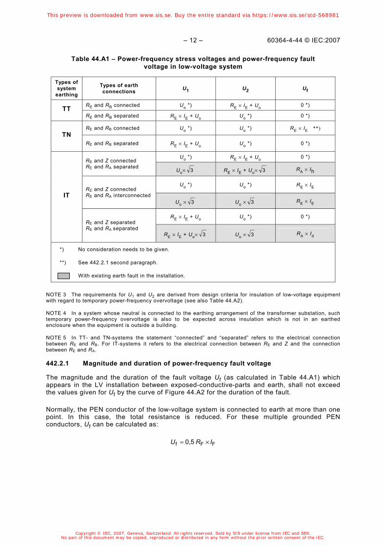
Table 44.A1 – Power-frequency stress voltages and power-frequency fault voltage in low-voltage system
Types of system
earthing
Types of earth connections U1 U2 Uf
RE and RB connected Uo *) RE × IE + Uo 0 *) TT RE and RB separated RE × IE + Uo Uo *) 0 *)
RE and RB connected Uo *) Uo *) RE × IE **) TN
RE and RB separated RE × IE + Uo Uo *) 0 *)
Uo *) RE × IE + Uo 0 *) RE and Z connected RE and RA separated
Uo× 3 RE × IE + Uo× 3 RA × Ih
Uo *) Uo *) RE × IE RE and Z connected RE and RA interconnected
Uo × 3 Uo × 3 RE × IE
RE × IE + Uo Uo *) 0 *)
IT
RE and Z separated RE and RA separated
RE × IE + Uo× 3 Uo × 3 RA × Id
*) No consideration needs to be given.
**) See 442.2.1 second paragraph.
With existing earth fault in the installation.
NOTE 3 The requirements for U1 and U2 are derived from design criteria for insulation of low-voltage equipment with regard to temporary power-frequency overvoltage (see also Table 44.A2).
NOTE 4 In a system whose neutral is connected to the earthing arrangement of the transformer substation, such temporary power-frequency overvoltage is also to be expected across insulation which is not in an earthed enclosure when the equipment is outside a building.
NOTE 5 In TT- and TN-systems the statement “connected” and “separated” refers to the electrical connection between RE and RB. For IT-systems it refers to the electrical connection between RE and Z and the connection between RE and RA.
442.2.1 Magnitude and duration of power-frequency fault voltage
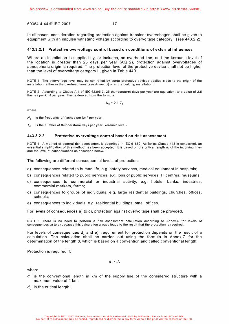
The magnitude and the duration of the fault voltage Uf (as calculated in Table 44.A1) which appears in the LV installation between exposed-conductive-parts and earth, shall not exceed the values given for Uf by the curve of Figure 44.A2 for the duration of the fault.
Normally, the PEN conductor of the low-voltage system is connected to earth at more than one point. In this case, the total resistance is reduced. For these multiple grounded PEN conductors, Uf can be calculated as:
FFf 0,5 IRU ×=
This preview is downloaded from www.sis.se. Buy the entire standard via https://www.sis.se/std-568981
Copyright © IEC, 2007, Geneva, Switzerland. All rights reserved. Sold by SIS under license from IEC and SEK.No part of this document may be copied, reproduced or distributed in any form without the prior written consent of the IEC.

60364-4-44 © IEC:2007 – 13 –
Fault voltage duration
0
100
200
300
400
500
600
700
800
900
1 000
1 100
1 200
10 100 1 000 10 000Time of duration t (ms)
Faul
t vol
tage
Uf
(V
)
IEC 1380/07
Figure 44.A2 – Tolerable fault voltage due to an earth-fault in the HV system
NOTE The curve shown in Figure 44.A2 is taken from IEC 61936-1. On the basis of probabilistic and statistical evidence this curve represents a low level of risk for the simple worst case where the low voltage system neutral conductor is earthed only at the transformer substation earthing arrangements. Guidance is provided in IEC 61936-1 concerning other situations.
442.2.2 Magnitude and duration of power-frequency stress voltages
The magnitude and the duration of the power-frequency stress voltage (U1 and U2) as calculated in Table 44.A1 of the low-voltage equipment in the low-voltage installation due to an earth fault in the high-voltage system shall not exceed the requirements given in Table 44.A2.
Table 44.A2 – Permissible power-frequency stress voltage
Duration of the earth fault in the high-voltage system
t
Permissible power-frequency stress voltage on equipment in low-voltage installations
U
>5 s
≤5 s
Uo + 250 V
Uo + 1 200 V
In systems without a neutral conductor, Uo shall be the line-to-line voltage.
NOTE 1 The first line of the table relates to high-voltage systems having long disconnection times, for example, isolated neutral and resonant earthed high-voltage systems. The second line relates to high-voltage systems having short disconnection times, for example low-impedance earthed high-voltage systems. Both lines together are relevant design criteria for insulation of low-voltage equipment with regard to temporary power frequency overvoltage, see IEC 60664-1.
NOTE 2 In a system whose neutral is connected to the earthing arrangement of the transformer substation, such temporary power-frequency overvoltage is also to be expected across insulation which is not in an earthed enclosure when the equipment is outside a building.
This preview is downloaded from www.sis.se. Buy the entire standard via https://www.sis.se/std-568981
Copyright © IEC, 2007, Geneva, Switzerland. All rights reserved. Sold by SIS under license from IEC and SEK.No part of this document may be copied, reproduced or distributed in any form without the prior written consent of the IEC.

– 14 – 60364-4-44 © IEC:2007
442.2.3 Requirements for calculation of limits
Where required by Table 44.A1, the permissible power-frequency stress voltage shall not exceed the value given in Table 44.A2.
Where required by Table 44.A1, the permissible power-frequency fault voltage shall not exceed the value given in Figure 44.A2.
The requirements of 442.2.1 and 442.2.2 are deemed to be fulfilled for installations receiving a supply at low-voltage from a public electricity distribution system.
To fulfil the above requirements, coordination between the HV-system operator and the LV-system installer is necessary. Compliance with the above requirements mainly falls into the responsibility of the substation installer/owner/operator who needs also to fulfil requirements provided by IEC 61936-1. Therefore the calculation for U1, U2 and Uf is normally not necessary for the LV system installer.
Possible measures to fulfil the above requirements are e.g.
• separation of earthing arrangement between HV and LV;
• change of LV system earthing;
• reduction of earth resistance RE.
442.3 Power-frequency stress voltage in case of loss of the neutral conductor in a TN and TT system
Consideration shall be given to the fact that, if the neutral conductor in a multi-phase system is interrupted, basic, double and reinforced insulation as well as components rated for the voltage between line and neutral conductors can be temporarily stressed with the line-to-Iine voltage. The stress voltage can reach up to U = √3 Uo.
442.4 Power-frequency stress voltage in the event of an earth fault in an IT system with distributed neutral
Consideration shall be given to the fact that, if a line conductor of an IT system is earthed accidentally, insulation or components rated for the voltage between line and neutral conductors can be temporarily stressed with the line-to-Iine voltage. The stress voltage can reach up to U = √3 Uo.
442.5 Power-frequency stress voltage in the event of a short-circuit between a line conductor and the neutral conductor
Consideration shall be given to the fact that if a short-circuit occurs in the low-voltage installation between a phase conductor and the neutral conductor, the voltage between the other line conductors and the neutral conductor can reach the value of 1,45 x Uo for a time up to 5 s.
443 Protection against overvoltages of atmospheric origin or due to switching
443.1 General
This clause of IEC 60364-4-44 deals with protection of electrical installations against transient overvoltages of atmospheric origin transmitted by the supply distribution system and against switching overvoltages.
In general, switching overvoltages are lower than overvoltages of atmospheric origin and therefore the requirements regarding protection against overvoltages of atmospheric origin normally cover protection against switching overvoltages.
This preview is downloaded from www.sis.se. Buy the entire standard via https://www.sis.se/std-568981
Copyright © IEC, 2007, Geneva, Switzerland. All rights reserved. Sold by SIS under license from IEC and SEK.No part of this document may be copied, reproduced or distributed in any form without the prior written consent of the IEC.

60364-4-44 © IEC:2007 – 15 –
NOTE 1 Statistical evaluations of measurements have shown that there is a low risk of switching overvoltages higher than the level of overvoltage category II. See 443.2.
Consideration shall be given to the overvoltages which can appear at the origin of an installation, to the expected keraunic level and to the location and characteristics of surge protective devices, so that the probability of incidents due to overvoltage stresses is reduced to an acceptable level for the safety of persons and property, as well as for the continuity of service desired.
The values of transient overvoltages depend on the nature of the supply distribution system (underground or overhead) and the possible existence of a surge protective device upstream of the origin of the installation and the voltage level of the supply system.
This clause provides guidance where protection against overvoltages is covered by inherent control or assured by protective control. If the protection according to this clause is not provided, insulation co-ordination is not assured and the risk due to overvoltages shall be evaluated.
This clause does not apply in case of overvoltages due to direct or nearby lightning. For protection against transient overvoltages due to direct lightning, IEC 62305-1, IEC 62305-3, IEC 62305-4 and the IEC 61643 series are applicable. This clause does not cover overvoltage through data-transmission systems.
NOTE 2 As regards transient atmospheric overvoltages, no distinction is made between earthed and unearthed systems.
NOTE 3 Switching overvoltages generated outside the installation and transmitted by the supply network are under consideration.
NOTE 4 The risk due to overvoltages is considered in IEC 61662 and its amendment 1.
443.2 Classification of impulse withstand voltages (overvoltage categories)
443.2.1 Purpose of classification of impulse withstand voltages (overvoltage categories)
NOTE 1 Overvoltage categories are defined within electrical installations for the purpose of insulation co-ordination and a related classification of equipment with impulse withstand voltages is provided, see Table 44B.
NOTE 2 The rated impulse withstand voltage is an impulse withstand voltage assigned by the manufacturer to the equipment or to a part of it, characterizing the specified withstand capability of its insulation against overvoltages (in accordance with 3.9.2 of IEC 60664-1).
The impulse withstand voltage (overvoltage category) is used to classify equipment energized directly from the mains.
Impulse withstand voltages for equipment selected according to the nominal voltage are provided to distinguish different levels of availability of equipment with regard to continuity of service and an acceptable risk of failure. By selection of equipment with a classified impulse withstand voltage, insulation co-ordination can be achieved in the whole installation, reducing the risk of failure to an acceptable level.
NOTE 3 Transient overvoltages transmitted by the supply distribution system are not significantly attenuated downstream in most installations.
443.2.2 Relationship between impulse withstand voltages of equipment and overvoltage categories
Equipment with an impulse withstand voltage corresponding to overvoltage category IV is suitable for use at, or in the proximity of, the origin of the installation, for example upstream of the main distribution board. Equipment of category IV has a very high impulse withstand capability providing the required high degree of reliability.
This preview is downloaded from www.sis.se. Buy the entire standard via https://www.sis.se/std-568981
Copyright © IEC, 2007, Geneva, Switzerland. All rights reserved. Sold by SIS under license from IEC and SEK.No part of this document may be copied, reproduced or distributed in any form without the prior written consent of the IEC.

– 16 – 60364-4-44 © IEC:2007
NOTE 1 Examples of such equipment are electricity meters, primary overcurrent protection devices and ripple control units.
Equipment with an impulse withstand voltage corresponding to overvoltage category III is for use in the fixed installation downstream of, and including the main distribution board, providing a high degree of availability.
NOTE 2 Examples of such equipment are distribution boards, circuit-breakers, wiring systems (see IEC 60050-826, definition 826-15-01), including cables, bus-bars, junction boxes, switches, socket-outlets) in the fixed installation, and equipment for industrial use and some other equipment, e.g. stationary motors with permanent connection to the fixed installation.
Equipment with an impulse withstand voltage corresponding to overvoltage category II is suitable for connection to the fixed electrical installation, providing a normal degree of availability normally required for current-using equipment.
NOTE 3 Examples of such equipment are household appliances and similar loads.
Equipment with an impulse withstand voltage corresponding to overvoltage category I is only suitable for use in the fixed installation of buildings where protective means are applied outside the equipment – to limit transient overvoltages to the specified level.
NOTE 4 Examples of such equipment are those containing electronic circuits like computers, appliances with electronic programmes, etc.
Equipment with an impulse withstand voltage corresponding to overvoltage category I shall not have direct connection to a public supply system.
443.3 Arrangements for overvoltage control
Overvoltage control is arranged in accordance with the following requirements.
443.3.1 Inherent overvoltage control
This subclause does not apply when a risk assessment according to 443.3.2.2 is used.
Where an installation is supplied by a completely buried low-voltage system and does not include overhead lines, the impulse withstand voltage of equipment in accordance with Table 44B is sufficient and no specific protection against overvoltages of atmospheric origin is necessary.
NOTE 1 A suspended cable having insulated conductors with earthed metallic screen is considered as equivalent to an underground cable.
Where an installation is supplied by or includes a low-voltage overhead line and the keraunic level is lower than or equal to 25 days per year (AQ 1), no specific protection against over-voltages of atmospheric origin is required.
NOTE 2 Irrespective of the AQ value, protection against overvoltages may be necessary in applications where a higher reliability or higher risks (e.g. fire) are expected.
In both cases, consideration regarding protection against transient overvoltages shall be given to equipment with an impulse withstand voltage according to overvoltage category I (see 443.2.2).
443.3.2 Protective overvoltage control
The decision as to which of the following methods are applied in a country with regard to the provision of surge protective devices (SPDs) is left to the national committee based on the local conditions.
This preview is downloaded from www.sis.se. Buy the entire standard via https://www.sis.se/std-568981
Copyright © IEC, 2007, Geneva, Switzerland. All rights reserved. Sold by SIS under license from IEC and SEK.No part of this document may be copied, reproduced or distributed in any form without the prior written consent of the IEC.
60364-4-44 © IEC:2007 – 17 –
In all cases, consideration regarding protection against transient overvoltages shall be given to equipment with an impulse withstand voltage according to overvoltage category I (see 443.2.2).
443.3.2.1 Protective overvoltage control based on conditions of external influences
Where an installation is supplied by, or includes, an overhead line, and the keraunic level of the location is greater than 25 days per year (AQ 2), protection against overvoltages of atmospheric origin is required. The protection level of the protective device shall not be higher than the level of overvoltage category II, given in Table 44B.
NOTE 1 The overvoltage level may be controlled by surge protective devices applied close to the origin of the installation, either in the overhead lines (see Annex B) or in the building installation.
NOTE 2 According to Clause A.1 of IEC 62305-3, 25 thunderstorm days per year are equivalent to a value of 2,5 flashes per km2 per year. This is derived from the formula
Ng = 0,1 Td
where
Ng is the frequency of flashes per km2 per year;
Td is the number of thunderstorm days per year (keraunic level).
443.3.2.2 Protective overvoltage control based on risk assessment
NOTE 1 A method of general risk assessment is described in IEC 61662. As far as Clause 443 is concerned, an essential simplification of this method has been accepted. It is based on the critical length dC of the incoming lines and the level of consequences as described below.
The following are different consequential levels of protection:
a) consequences related to human life, e.g. safety services, medical equipment in hospitals; b) consequences related to public services, e.g. loss of public services, IT centres, museums; c) consequences to commercial or industrial activity, e.g. hotels, banks, industries,
commercial markets, farms; d) consequences to groups of individuals, e.g. large residential buildings, churches, offices,
schools; e) consequences to individuals, e.g. residential buildings, small offices.
For levels of consequences a) to c), protection against overvoltage shall be provided.
NOTE 2 There is no need to perform a risk assessment calculation according to Annex C for levels of consequences a) to c) because this calculation always leads to the result that the protection is required.
For levels of consequences d) and e), requirement for protection depends on the result of a calculation. The calculation shall be carried out using the formula in Annex C for the determination of the length d, which is based on a convention and called conventional length.
Protection is required if:
d > dc
where d is the conventional length in km of the supply line of the considered structure with a
maximum value of 1 km; dc is the critical length;
This preview is downloaded from www.sis.se. Buy the entire standard via https://www.sis.se/std-568981
Copyright © IEC, 2007, Geneva, Switzerland. All rights reserved. Sold by SIS under license from IEC and SEK.No part of this document may be copied, reproduced or distributed in any form without the prior written consent of the IEC.