Edition 2.0 2016-01 INTERNATIONAL STANDARD NORME ...
19
IEC 60909-0 Edition 2.0 2016-01 INTERNATIONAL STANDARD NORME INTERNATIONALE Short-circuit currents in three-phase a.c. systems – Part 0: Calculation of currents Courants de court-circuit dans les réseaux triphasés à courant alternatif – Partie 0: Calcul des courants IEC 60909-0:2016-01(en-fr) ® This preview is downloaded from www.sis.se. Buy the entire standard via https://www.sis.se/std-8018642 Copyright © IEC, 2016, Geneva, Switzerland. All rights reserved. Sold by SIS under license from IEC and SEK. No part of this document may be copied, reproduced or distributed in any form without the prior written consent of the IEC.
Transcript of Edition 2.0 2016-01 INTERNATIONAL STANDARD NORME ...

IEC 60909-0 Edition 2.0 2016-01
INTERNATIONAL STANDARD NORME INTERNATIONALE
Short-circuit currents in three-phase a.c. systems – Part 0: Calculation of currents Courants de court-circuit dans les réseaux triphasés à courant alternatif – Partie 0: Calcul des courants
IEC
609
09-0
:201
6-01
(en-
fr)
®
This preview is downloaded from www.sis.se. Buy the entire standard via https://www.sis.se/std-8018642
Copyright © IEC, 2016, Geneva, Switzerland. All rights reserved. Sold by SIS under license from IEC and SEK.No part of this document may be copied, reproduced or distributed in any form without the prior written consent of the IEC.
THIS PUBLICATION IS COPYRIGHT PROTECTED Copyright © 2016 IEC, Geneva, Switzerland All rights reserved. Unless otherwise specified, no part of this publication may be reproduced or utilized in any form or by any means, electronic or mechanical, including photocopying and microfilm, without permission in writing from either IEC or IEC's member National Committee in the country of the requester. If you have any questions about IEC copyright or have an enquiry about obtaining additional rights to this publication, please contact the address below or your local IEC member National Committee for further information. Droits de reproduction réservés. Sauf indication contraire, aucune partie de cette publication ne peut être reproduite ni utilisée sous quelque forme que ce soit et par aucun procédé, électronique ou mécanique, y compris la photocopie et les microfilms, sans l'accord écrit de l'IEC ou du Comité national de l'IEC du pays du demandeur. Si vous avez des questions sur le copyright de l'IEC ou si vous désirez obtenir des droits supplémentaires sur cette publication, utilisez les coordonnées ci-après ou contactez le Comité national de l'IEC de votre pays de résidence.
IEC Central Office Tel.: +41 22 919 02 11 3, rue de Varembé Fax: +41 22 919 03 00 CH-1211 Geneva 20 [email protected] Switzerland www.iec.ch
About the IEC The International Electrotechnical Commission (IEC) is the leading global organization that prepares and publishes International Standards for all electrical, electronic and related technologies. About IEC publications The technical content of IEC publications is kept under constant review by the IEC. Please make sure that you have the latest edition, a corrigenda or an amendment might have been published. IEC Catalogue - webstore.iec.ch/catalogue The stand-alone application for consulting the entire bibliographical information on IEC International Standards, Technical Specifications, Technical Reports and other documents. Available for PC, Mac OS, Android Tablets and iPad. IEC publications search - www.iec.ch/searchpub The advanced search enables to find IEC publications by a variety of criteria (reference number, text, technical committee,…). It also gives information on projects, replaced and withdrawn publications. IEC Just Published - webstore.iec.ch/justpublished Stay up to date on all new IEC publications. Just Published details all new publications released. Available online and also once a month by email.
Electropedia - www.electropedia.org The world's leading online dictionary of electronic and electrical terms containing 20 000 terms and definitions in English and French, with equivalent terms in 15 additional languages. Also known as the International Electrotechnical Vocabulary (IEV) online. IEC Glossary - std.iec.ch/glossary 65 000 electrotechnical terminology entries in English and French extracted from the Terms and Definitions clause of IEC publications issued since 2002. Some entries have been collected from earlier publications of IEC TC 37, 77, 86 and CISPR. IEC Customer Service Centre - webstore.iec.ch/csc If you wish to give us your feedback on this publication or need further assistance, please contact the Customer Service Centre: [email protected].
A propos de l'IEC La Commission Electrotechnique Internationale (IEC) est la première organisation mondiale qui élabore et publie des Normes internationales pour tout ce qui a trait à l'électricité, à l'électronique et aux technologies apparentées. A propos des publications IEC Le contenu technique des publications IEC est constamment revu. Veuillez vous assurer que vous possédez l’édition la plus récente, un corrigendum ou amendement peut avoir été publié. Catalogue IEC - webstore.iec.ch/catalogue Application autonome pour consulter tous les renseignements bibliographiques sur les Normes internationales, Spécifications techniques, Rapports techniques et autres documents de l'IEC. Disponible pour PC, Mac OS, tablettes Android et iPad. Recherche de publications IEC - www.iec.ch/searchpub La recherche avancée permet de trouver des publications IEC en utilisant différents critères (numéro de référence, texte, comité d’études,…). Elle donne aussi des informations sur les projets et les publications remplacées ou retirées. IEC Just Published - webstore.iec.ch/justpublished Restez informé sur les nouvelles publications IEC. Just Published détaille les nouvelles publications parues. Disponible en ligne et aussi une fois par mois par email.
Electropedia - www.electropedia.org Le premier dictionnaire en ligne de termes électroniques et électriques. Il contient 20 000 termes et définitions en anglais et en français, ainsi que les termes équivalents dans 15 langues additionnelles. Egalement appelé Vocabulaire Electrotechnique International (IEV) en ligne. Glossaire IEC - std.iec.ch/glossary 65 000 entrées terminologiques électrotechniques, en anglais et en français, extraites des articles Termes et Définitions des publications IEC parues depuis 2002. Plus certaines entrées antérieures extraites des publications des CE 37, 77, 86 et CISPR de l'IEC. Service Clients - webstore.iec.ch/csc Si vous désirez nous donner des commentaires sur cette publication ou si vous avez des questions contactez-nous: [email protected].
This preview is downloaded from www.sis.se. Buy the entire standard via https://www.sis.se/std-8018642
Copyright © IEC, 2016, Geneva, Switzerland. All rights reserved. Sold by SIS under license from IEC and SEK.No part of this document may be copied, reproduced or distributed in any form without the prior written consent of the IEC.
IEC 60909-0 Edition 2.0 2016-01
INTERNATIONAL STANDARD NORME INTERNATIONALE
Short-circuit currents in three-phase a.c. systems – Part 0: Calculation of currents Courants de court-circuit dans les réseaux triphasés à courant alternatif – Partie 0: Calcul des courants
INTERNATIONAL ELECTROTECHNICAL COMMISSION
COMMISSION ELECTROTECHNIQUE INTERNATIONALE ICS 17.220.01; 29.240.20
ISBN 978-2-8322-3158-6
® Registered trademark of the International Electrotechnical Commission Marque déposée de la Commission Electrotechnique Internationale
®
Warning! Make sure that you obtained this publication from an authorized distributor. Attention! Veuillez vous assurer que vous avez obtenu cette publication via un distributeur agréé.
This preview is downloaded from www.sis.se. Buy the entire standard via https://www.sis.se/std-8018642
Copyright © IEC, 2016, Geneva, Switzerland. All rights reserved. Sold by SIS under license from IEC and SEK.No part of this document may be copied, reproduced or distributed in any form without the prior written consent of the IEC.

– 2 – IEC 60909-0:2016 © IEC 2016
CONTENTS
FOREWORD ......................................................................................................................... 5 1 Scope ............................................................................................................................ 7 2 Normative references..................................................................................................... 8 3 Terms and definitions .................................................................................................... 8 4 Symbols, subscripts and superscripts ........................................................................... 13
4.1 General ............................................................................................................... 13 4.2 Symbols .............................................................................................................. 13 4.3 Subscripts ........................................................................................................... 15 4.4 Superscripts ........................................................................................................ 16
5 Characteristics of short-circuit currents: calculating method .......................................... 16 5.1 General ............................................................................................................... 16 5.2 Calculation assumptions ...................................................................................... 19 5.3 Method of calculation .......................................................................................... 20
5.3.1 Equivalent voltage source at the short-circuit location ................................... 20 5.3.2 Symmetrical components ............................................................................. 22
6 Short-circuit impedances of electrical equipment .......................................................... 23 6.1 General ............................................................................................................... 23 6.2 Network feeders .................................................................................................. 23 6.3 Transformers ...................................................................................................... 25
6.3.1 Two-winding transformers ............................................................................ 25 6.3.2 Three-winding transformers .......................................................................... 25 6.3.3 Impedance correction factors for two- and three-winding network
transformers ................................................................................................ 27 6.4 Overhead lines and cables .................................................................................. 28 6.5 Short-circuit current-limiting reactors ................................................................... 29 6.6 Synchronous machines ....................................................................................... 29
6.6.1 Synchronous generators .............................................................................. 29 6.6.2 Synchronous compensators and motors........................................................ 31
6.7 Power station units .............................................................................................. 31 6.7.1 Power station units with on-load tap-changer ................................................ 31 6.7.2 Power station units without on-load tap-changer ........................................... 32
6.8 Wind power station units ..................................................................................... 33 6.8.1 General ....................................................................................................... 33 6.8.2 Wind power station units with asynchronous generator ................................. 33 6.8.3 Wind power station units with doubly fed asynchronous generator ................. 34
6.9 Power station units with full size converter ........................................................... 35 6.10 Asynchronous motors .......................................................................................... 35 6.11 Static converter fed drives ................................................................................... 36 6.12 Capacitors and non-rotating loads ....................................................................... 36
7 Calculation of initial short-circuit current ....................................................................... 36 7.1 General ............................................................................................................... 36
7.1.1 Overview ..................................................................................................... 36 7.1.2 Maximum and minimum short-circuit currents ............................................... 41 7.1.3 Contribution of asynchronous motors to the short-circuit current .................... 42
7.2 Three-phase initial short-circuit current ................................................................ 43 7.2.1 General ....................................................................................................... 43
This preview is downloaded from www.sis.se. Buy the entire standard via https://www.sis.se/std-8018642
Copyright © IEC, 2016, Geneva, Switzerland. All rights reserved. Sold by SIS under license from IEC and SEK.No part of this document may be copied, reproduced or distributed in any form without the prior written consent of the IEC.

IEC 60909-0:2016 © IEC 2016 – 3 –
7.2.2 Short-circuit currents inside a power station unit with on-load tap-changer ....................................................................................................... 44
7.2.3 Short-circuit currents inside a power station unit without on-load tap-changer ....................................................................................................... 46
7.3 Line-to-line short circuit ....................................................................................... 47 7.4 Line-to-line short circuit with earth connection ..................................................... 47 7.5 Line-to-earth short circuit .................................................................................... 49
8 Calculation of peak short-circuit current ....................................................................... 49 8.1 Three-phase short circuit ..................................................................................... 49
8.1.1 Single-fed and multiple single-fed short circuits ............................................ 49 8.1.2 Multiple-fed short circuit ............................................................................... 51
8.2 Line-to-line short circuit ....................................................................................... 52 8.3 Line-to-line short circuit with earth connection ..................................................... 52 8.4 Line-to-earth short circuit .................................................................................... 52
9 Calculation of symmetrical breaking current ................................................................. 53 9.1 Three-phase short circuit ..................................................................................... 53
9.1.1 Symmetrical breaking current of synchronous machines................................ 53 9.1.2 Symmetrical breaking current of asynchronous machines .............................. 54 9.1.3 Symmetrical breaking current of power station units with doubly fed
asynchronous generator ............................................................................... 55 9.1.4 Symmetrical breaking current of power station units with full size
converter ..................................................................................................... 55 9.1.5 Symmetrical breaking current of network feeder ............................................ 56 9.1.6 Symmetrical breaking current in case of multiple single-fed short-
circuits ......................................................................................................... 56 9.1.7 Symmetrical breaking current in case of multiple-fed short circuits ................ 56
9.2 Unbalanced short-circuits .................................................................................... 57 10 DC component of the short-circuit current .................................................................... 57 11 Calculation of steady-state short-circuit current ............................................................ 58
11.1 General ............................................................................................................... 58 11.2 Three-phase short circuit ..................................................................................... 58
11.2.1 Steady-state short-circuit current of one synchronous generator or one power station unit ......................................................................................... 58
11.2.2 Steady-state short-circuit current of asynchronous motor or generator........... 61 11.2.3 Steady-state short-circuit current of wind power station unit with doubly
fed asynchronous generator ......................................................................... 61 11.2.4 Steady-state short-circuit current of wind power station unit with full size
converter ..................................................................................................... 61 11.2.5 Steady-state short-circuit current of network feeder ...................................... 61 11.2.6 Steady-state short-circuit current in case of multiple single-fed short
circuits ......................................................................................................... 61 11.2.7 Steady-state short-circuit current in case of multiple-fed short circuits ........... 62
11.3 Unbalanced short circuits .................................................................................... 62 12 Short circuits at the low-voltage side of transformers, if one line conductor is
interrupted at the high-voltage side .............................................................................. 62 13 Terminal short circuit of asynchronous motors .............................................................. 64 14 Joule integral and thermal equivalent short-circuit current............................................. 65 Annex A (normative) Formulas for the calculation of the factors m and n ............................. 68 Annex B (informative) Nodal admittance and nodal impedance matrices .............................. 69 Bibliography ....................................................................................................................... 73
This preview is downloaded from www.sis.se. Buy the entire standard via https://www.sis.se/std-8018642
Copyright © IEC, 2016, Geneva, Switzerland. All rights reserved. Sold by SIS under license from IEC and SEK.No part of this document may be copied, reproduced or distributed in any form without the prior written consent of the IEC.

– 4 – IEC 60909-0:2016 © IEC 2016
Figure 1 – Short-circuit current of a far-from-generator short circuit with constant AC component (schematic diagram) .......................................................................................... 17 Figure 2 – Short-circuit current of a near-to-generator short-circuit with decaying AC component (schematic diagram) .......................................................................................... 18 Figure 3 – Characterization of short-circuits and their currents ............................................. 19
Figure 4 – Illustration for calculating the initial symmetrical short-circuit current "kI in
compliance with the procedure for the equivalent voltage source ......................................... 21 Figure 5 – System diagram and equivalent circuit diagram for network feeders .................... 24 Figure 6 – Three-winding transformer (example) .................................................................. 27 Figure 7 – Diagram to determine the short-circuit type (Figure 3) for the highest initial short-circuit current referred to the initial three-phase short-circuit current when the impedance angles of the sequence impedances Z(1), Z(2), Z(0) are identical ....................... 38 Figure 8 – Examples of single-fed short-circuits ................................................................... 40 Figure 9 – Example of a multiple single-fed short circuit ...................................................... 40 Figure 10 – Example of multiple-fed short circuit ................................................................. 41 Figure 11 – Short-circuit currents and partial short-circuit currents for three-phase short circuits between generator and unit transformer with or without on-load tap-changer, or at the connection to the auxiliary transformer of a power station unit and at the auxiliary busbar A ......................................................................................................... 45 Figure 12 – Factor κ for series circuit as a function of ratio R/X or X/R .................................. 50 Figure 13 – Factor µ for calculation of short-circuit breaking current Ib................................. 54 Figure 14 – Factor q for the calculation of the symmetrical short-circuit breaking current of asynchronous motors .......................................................................................... 55 Figure 15 – Factors λmin and λmax factors for cylindrical rotor generators ........................... 60 Figure 16 – Factors λmin and λmax for salient-pole generators ............................................ 60 Figure 17 – Transformer secondary short-circuits, if one line (fuse) is opened on the high-voltage side of a transformer Dyn5 .............................................................................. 63 Figure 18 – Factor m for the heat effect of the DC component of the short-circuit current (for programming, the formula to calculate m is given in Annex A) ............................ 66 Figure 19 – Factor n for the heat effect of the AC component of the short-circuit current (for programming, the formula to calculate n is given in Annex A) ......................................... 67 Figure B.1 – Formulation of the nodal admittance matrix ...................................................... 70 Figure B.2 – Example ......................................................................................................... 71 Table 1 – Voltage factor c ................................................................................................... 22 Table 2 – Importance of short-circuit currents ...................................................................... 37 Table 3 – Factors α and β for the calculation of short-circuit currents with Formula (96), rated transformation ratio tr = UrTHV/UrTLV ................................................................ 64 Table 4 – Calculation of short-circuit currents of asynchronous motors in the case of a short circuit at the terminals ................................................................................................ 65 Table B.1 – Impedances of electrical equipment referred to the 110 kV side ......................... 71
This preview is downloaded from www.sis.se. Buy the entire standard via https://www.sis.se/std-8018642
Copyright © IEC, 2016, Geneva, Switzerland. All rights reserved. Sold by SIS under license from IEC and SEK.No part of this document may be copied, reproduced or distributed in any form without the prior written consent of the IEC.
IEC 60909-0:2016 © IEC 2016 – 5 –
INTERNATIONAL ELECTROTECHNICAL COMMISSION
____________
SHORT-CIRCUIT CURRENTS IN THREE-PHASE AC SYSTEMS –
Part 0: Calculation of currents
FOREWORD
1) The International Electrotechnical Commission (IEC) is a worldwide organization for standardization comprising all national electrotechnical committees (IEC National Committees). The object of IEC is to promote international co-operation on all questions concerning standardization in the electrical and electronic fields. To this end and in addition to other activities, IEC publishes International Standards, Technical Specifications, Technical Reports, Publicly Available Specifications (PAS) and Guides (hereafter referred to as “IEC Publication(s)”). Their preparation is entrusted to technical committees; any IEC National Committee interested in the subject dealt with may participate in this preparatory work. International, governmental and non-governmental organizations liaising with the IEC also participate in this preparation. IEC collaborates closely with the International Organization for Standardization (ISO) in accordance with conditions determined by agreement between the two organizations.
2) The formal decisions or agreements of IEC on technical matters express, as nearly as possible, an international consensus of opinion on the relevant subjects since each technical committee has representation from all interested IEC National Committees.
3) IEC Publications have the form of recommendations for international use and are accepted by IEC National Committees in that sense. While all reasonable efforts are made to ensure that the technical content of IEC Publications is accurate, IEC cannot be held responsible for the way in which they are used or for any misinterpretation by any end user.
4) In order to promote international uniformity, IEC National Committees undertake to apply IEC Publications transparently to the maximum extent possible in their national and regional publications. Any divergence between any IEC Publication and the corresponding national or regional publication shall be clearly indicated in the latter.
5) IEC itself does not provide any attestation of conformity. Independent certification bodies provide conformity assessment services and, in some areas, access to IEC marks of conformity. IEC is not responsible for any services carried out by independent certification bodies.
6) All users should ensure that they have the latest edition of this publication.
7) No liability shall attach to IEC or its directors, employees, servants or agents including individual experts and members of its technical committees and IEC National Committees for any personal injury, property damage or other damage of any nature whatsoever, whether direct or indirect, or for costs (including legal fees) and expenses arising out of the publication, use of, or reliance upon, this IEC Publication or any other IEC Publications.
8) Attention is drawn to the Normative references cited in this publication. Use of the referenced publications is indispensable for the correct application of this publication.
9) Attention is drawn to the possibility that some of the elements of this IEC Publication may be the subject of patent rights. IEC shall not be held responsible for identifying any or all such patent rights.
International Standard IEC 60909-0 has been prepared by IEC technical committee 73: Short-circuit currents.
This second edition cancels and replaces the first edition published in 2001. This edition constitutes a technical revision.
This edition includes the following significant technical changes with respect to the previous edition:
a) contribution of windpower station units to the short-circuit current; b) contribution of power station units with ful size converters to the short-circuit current; c) new document structure.
This preview is downloaded from www.sis.se. Buy the entire standard via https://www.sis.se/std-8018642
Copyright © IEC, 2016, Geneva, Switzerland. All rights reserved. Sold by SIS under license from IEC and SEK.No part of this document may be copied, reproduced or distributed in any form without the prior written consent of the IEC.

– 6 – IEC 60909-0:2016 © IEC 2016
The text of this standard is based on the following documents:
CDV Report on voting
73/172/CDV 73/175A/RVC
Full information on the voting for the approval of this standard can be found in the report on voting indicated in the above table.
This publication has been drafted in accordance with the ISO/IEC Directives, Part 2.
A list of all parts in the IEC 60909 series, published under the general title Short-circuit currents in three-phase a.c. systems, can be found on the IEC website.
This part of IEC 60909 is to be read in conjunction with the following International Standards and Technical Reports:
– IEC TR 60909-1:2002, Short-circuit currents in three-phase a.c. systems – Part 1: Factors for the calculation of short-circuit currents according to IEC 60909-0
– IEC TR 60909-2:2008, Short-circuit currents in three-phase a.c. systems – Part 2: Data of electrical equipment for short-circuit current calculations
– IEC 60909-3:2009, Short-circuit currents in three-phase a.c. systems – Part 3: Currents during two separate simultaneous line-to-earth short circuits and partial short-circuit currents flowing through earth
– IEC TR 60909-4:2000, Short-circuit currents in three-phase a.c. systems – Part 4: Examples for the calculation of short-circuit currents
The committee has decided that the contents of this publication will remain unchanged until the stability date indicated on the IEC website under "http://webstore.iec.ch" in the data related to the specific publication. At this date, the publication will be
• reconfirmed,
• withdrawn,
• replaced by a revised edition, or
• amended.
This preview is downloaded from www.sis.se. Buy the entire standard via https://www.sis.se/std-8018642
Copyright © IEC, 2016, Geneva, Switzerland. All rights reserved. Sold by SIS under license from IEC and SEK.No part of this document may be copied, reproduced or distributed in any form without the prior written consent of the IEC.

IEC 60909-0:2016 © IEC 2016 – 7 –
SHORT-CIRCUIT CURRENTS IN THREE-PHASE AC SYSTEMS –
Part 0: Calculation of currents
1 Scope
This part of IEC 60909 is applicable to the calculation of short-circuit currents
• in low-voltage three-phase AC systems, and
• in high-voltage three-phase AC systems,
operating at a nominal frequency of 50 Hz or 60 Hz.
Systems at highest voltages of 550 kV and above with long transmission lines need special consideration.
This part of IEC 60909 establishes a general, practicable and concise procedure leading to results which are generally of acceptable accuracy. For this calculation method, an equivalent voltage source at the short-circuit location is introduced. This does not exclude the use of special methods, for example the superposition method, adjusted to particular circumstances, if they give at least the same precision. The superposition method gives the short-circuit current related to the one load flow presupposed. This method, therefore, does not necessarily lead to the maximum short-circuit current.
This part of IEC 60909 deals with the calculation of short-circuit currents in the case of balanced or unbalanced short circuits.
A single line-to-earth fault is beyond the scope of this part of IEC 60909.
For currents during two separate simultaneous single-phase line-to-earth short circuits in an isolated neutral system or a resonance earthed neutral system, see IEC 60909-3.
Short-circuit currents and short-circuit impedances may also be determined by system tests, by measurement on a network analyser, or with a digital computer. In existing low-voltage systems it is possible to determine the short-circuit impedance on the basis of measurements at the location of the prospective short circuit considered.
The calculation of the short-circuit impedance is in general based on the rated data of the electrical equipment and the topological arrangement of the system and has the advantage of being possible both for existing systems and for systems at the planning stage.
In general, two types short-circuit currents, which differ in their magnitude, are considered:
• the maximum short-circuit current which determines the capacity or rating of electrical equipment; and
• the minimum short-circuit current which can be a basis, for example, for the selection of fuses, for the setting of protective devices, and for checking the run-up of motors.
NOTE The current in a three-phase short circuit is assumed to be made simultaneously in all poles. Investigations of non-simultaneous short circuits, which may lead to higher aperiodic components of short-circuit current, are beyond the scope of this part of IEC 60909.
This part of IEC 60909 does not cover short-circuit currents deliberately created under controlled conditions (short-circuit testing stations).
This preview is downloaded from www.sis.se. Buy the entire standard via https://www.sis.se/std-8018642
Copyright © IEC, 2016, Geneva, Switzerland. All rights reserved. Sold by SIS under license from IEC and SEK.No part of this document may be copied, reproduced or distributed in any form without the prior written consent of the IEC.

– 8 – IEC 60909-0:2016 © IEC 2016
This part of IEC 60909 does not deal with the calculation of short-circuit currents in installations on board ships and aeroplanes.
2 Normative references
The following documents, in whole or in part, are normatively referenced in this document and are indispensable for its application. For dated references, only the edition cited applies. For undated references, the latest edition of the referenced document (including any amendments) applies.
IEC 60038:2009, IEC standard voltages
IEC 60050-131, International Electrotechnical Vocabulary – Part 131: Circuit theory (available at: www.electropedia.org)
IEC TR 60909-1:2002, Short-circuit currents in three-phase a.c. systems – Part 1: Factors for the calculation of short-circuit currents according to IEC 60909-0
IEC TR 60909-2:2008, Short-circuit currents in three-phase a.c. systems – Data of electrical equipment for short-circuit current calculations
IEC 60909-3:2009, Short-circuit currents in three-phase a.c. systems – Part 3: Currents during two separate simultaneous line-to-earth short circuits and partial short-circuit currents flowing through earth
IEC TR 60909-4:2000, Short-circuit currents in three-phase a.c. systems – Part 4: Examples for the calculation of short-circuit currents
3 Terms and definitions
For the purposes of this document, the terms and definitions given in IEC 60050-131 and the following apply.
3.1 short circuit accidental or intentional conductive path between two or more conductive parts (e.g. three-phase short circuit) forcing the electric potential differences between these conductive parts to be equal or close to zero
3.1.1 line-to-line short circuit two-phase short circuit accidental or intentional conductive path between two line conductors with or without earth connection
3.1.2 line-to-earth short circuit single-phase short circuit accidental or intentional conductive path in a solidly earthed neutral system or an impedance earthed neutral system between a line conductor and local earth
3.2 short-circuit current over-current resulting from a short circuit in an electric system
This preview is downloaded from www.sis.se. Buy the entire standard via https://www.sis.se/std-8018642
Copyright © IEC, 2016, Geneva, Switzerland. All rights reserved. Sold by SIS under license from IEC and SEK.No part of this document may be copied, reproduced or distributed in any form without the prior written consent of the IEC.

IEC 60909-0:2016 © IEC 2016 – 9 –
Note 1 to entry: It is necessary to distinguish between the short-circuit current at the short-circuit location and partial short-circuit currents in the network branches (see Figure 3) at any point of the network.
3.3 prospective short-circuit current current that would flow if the short circuit were replaced by an ideal connection of negligible impedance without any change of the supply
Note 1 to entry: The current in a three-phase short circuit is assumed to be made simultaneously in all poles. Investigations of non-simultaneous short circuits, which may lead to higher aperiodic components of short-circuit current, are beyond the scope of this part of IEC 60909.
3.4 symmetrical short-circuit current rms value of the AC symmetrical component of a prospective short-circuit current (see 3.3), the aperiodic component of current, if any, being neglected
3.5 initial symmetrical short-circuit current
"kI
rms value of the AC symmetrical component of a prospective short-circuit current (see 3.3), applicable at the instant of short circuit if the impedance remains at zero-time value
SEE: Figures 1 and 2
3.6 initial symmetrical short-circuit power
"kS
fictitious value determined as a product of the initial symmetrical short-circuit current "kI (see
3.5), the nominal system voltage Un (see 3.13) and the factor 3 : "kn
"k 3 IUS ⋅⋅=
Note 1 to entry: The initial symmetrical short-circuit power "kS is not used for the calculation procedure in this part
of IEC 60909. If "kS is used in spite of this in connection with short-circuit calculations, for instance to calculate the
internal impedance of a network feeder at the connection point Q, then the definition given should be used in the
following form: "kQnQ
"kQ 3 IUS ⋅⋅= or "
kQ2nQQ / SUcZ ⋅= .
3.7 decaying (aperiodic) component of short-circuit current or DC component iDC mean value between the top and bottom envelope of a short-circuit current decaying from an initial value to zero according to Figures 1 and 2
3.8 peak short-circuit current ip maximum possible instantaneous value of the prospective short-circuit current
SEE: Figures 1 and 2
Note 1 to entry: Sequential short circuits are not considered.
3.9 symmetrical short-circuit breaking current Ib rms value of an integral cycle of the symmetrical AC component of the prospective short-circuit current at the instant of contact separation of the first pole to open of a switching device
This preview is downloaded from www.sis.se. Buy the entire standard via https://www.sis.se/std-8018642
Copyright © IEC, 2016, Geneva, Switzerland. All rights reserved. Sold by SIS under license from IEC and SEK.No part of this document may be copied, reproduced or distributed in any form without the prior written consent of the IEC.
– 10 – IEC 60909-0:2016 © IEC 2016
3.10 steady-state short-circuit current Ik rms value of the short-circuit current which remains after the decay of the transient phenomena
SEE: Figures 1 and 2
3.11 symmetrical locked-rotor current ILR symmetrical rms current of an asynchronous motor with locked rotor fed with rated voltage UrM at rated frequency
3.12 equivalent electric circuit model to describe the behaviour of a circuit by means of a network of ideal elements
3.13 nominal system voltage Un voltage (line-to-line) by which a system is designated, and to which certain operating characteristics are referred
Note 1 to entry: Values are given in IEC 60038.
3.14 equivalent voltage source
3/ncU voltage of an ideal source applied at the short-circuit location for calculating the short-circuit current according to 5.3.1
Note 1 to entry: This is the only active voltage of the network.
3.15 voltage factor c ratio between the equivalent voltage source and the nominal system voltage Un divided by
3
Note 1 to entry: The values are given in Table 1.
Note 2 to entry: The introduction of a voltage factor c is necessary for various reasons. These are:
– voltage variations depending on time and place, – changing of transformer taps, – neglecting loads and capacitances by calculations according to 5.2, – the subtransient behaviour of generators and motors.
3.16 far-from-generator short circuit short circuit during which the magnitude of the symmetrical AC component of the prospective short-circuit current remains essentially constant
SEE: Figure 1
3.17 near-to-generator short circuit short circuit during which the magnitude of the symmetrical AC component of the prospective short-circuit current decreases
This preview is downloaded from www.sis.se. Buy the entire standard via https://www.sis.se/std-8018642
Copyright © IEC, 2016, Geneva, Switzerland. All rights reserved. Sold by SIS under license from IEC and SEK.No part of this document may be copied, reproduced or distributed in any form without the prior written consent of the IEC.
IEC 60909-0:2016 © IEC 2016 – 11 –
SEE: Figure 2
Note 1 to entry: A near-to-generator short circuit can be assumed if at least one synchronous machine contributes a prospective initial symmetrical short-circuit current which is more than twice the machine's rated current, or a short circuit to which asynchronous motors contribute more than 5 % of the initial symmetrical short-circuit current without motors.
3.18 short-circuit impedances at the short-circuit location F 3.18.1 positive-sequence short-circuit impedance Z(1) <three-phase AC system> impedance of the positive-sequence system as viewed from the short-circuit location
Note 1 to entry: See 5.3.2.
3.18.2 short-circuit impedance Zk <three-phase AC system> abbreviated expression for the positive-sequence short-circuit impedance Z(1) according to 3.18.1 for the calculation of three-phase short-circuit currents
3.18.3 negative-sequence short-circuit impedance Z(2) <three-phase AC system> impedance of the negative-sequence system as viewed from the short-circuit location
Note 1 to entry: See 5.3.2.
3.18.4 zero-sequence short-circuit impedance Z(0) <three-phase AC system> impedance of the zero-sequence system as viewed from the short-circuit location (see 5.3.2)
Note 1 to entry: It includes three times the neutral-to-earth impedance ZN.
3.19 short-circuit impedances of electrical equipment 3.19.1 positive-sequence short-circuit impedance Z(1) <electrical equipment> ratio of the line-to-neutral voltage to the short-circuit current of the corresponding line conductor of electrical equipment when fed by a symmetrical positive-sequence system of voltages
Note 1 to entry: See Clause 6 and IEC TR 60909-4.
Note 2 to entry: The index of symbol Z(1) may be omitted if there is no possibility of confusion with the negative-sequence and the zero-sequence short-circuit impedances.
3.19.2 negative-sequence short-circuit impedance Z(2) <electrical equipment> ratio of the line-to-neutral voltage to the short-circuit current of the corresponding line conductor of electrical equipment when fed by a symmetrical negative-sequence system of voltages
Note 1 to entry: See Clause 6 and IEC TR 60909-4.
This preview is downloaded from www.sis.se. Buy the entire standard via https://www.sis.se/std-8018642
Copyright © IEC, 2016, Geneva, Switzerland. All rights reserved. Sold by SIS under license from IEC and SEK.No part of this document may be copied, reproduced or distributed in any form without the prior written consent of the IEC.
– 12 – IEC 60909-0:2016 © IEC 2016
3.19.3 zero-sequence short-circuit impedance Z(0) <electrical equipment> ratio of the line-to-earth voltage to the short-circuit current of one line conductor of electrical equipment when fed by an AC voltage source, if the three paralleled line conductors are used for the outgoing current and a fourth line and/or earth as a joint return
Note 1 to entry: See Clause 6 and IEC TR 60909-4.
3.20 subtransient reactance
"dX
effective reactance of a synchronous machine at the moment of short circuit
Note 1 to entry: For the calculation of short-circuit currents the saturated value of "dX is taken.
3.21 minimum time delay tmin shortest time between the beginning of the short-circuit current and the contact separation of the first pole to open of the switching device
Note 1 to entry: The time tmin is the sum of the shortest possible operating time of a protective relay and the shortest opening time of a circuit-breaker. It does not take into account adjustable time delays of tripping devices.
3.22 thermal equivalent short-circuit current Ith the rms value of a current having the same thermal effect and the same duration as the actual short-circuit current, which may contain a DC component and may subside in time
3.23 maximum short-circuit current ikWDmax <doubly fed asynchronous generator> instantaneous maximum short-circuit current of a wind power station unit with doubly fed asynchronous generator in case of a three-phase short-circuit at the high-voltage side of the unit transformer
3.24 maximum short-circuit current IkPFmax <full size converter> maximum steady state current of a power station unit with full size converter in case of a three-phase short-circuit at the high-voltage side of the unit transformer
3.25 maximum source current IskPF <full size converter, three phase> rms value of the maximum source current of a power station unit with full size converter and current regulation in case of three-phase short circuit at the high-voltage side of the unit transformer
3.26 maximum source current I(1)sk2PF <full size converter, two phase> rms value of the maximum source current (positive-sequence system) of a power station unit with full size converter and current regulation in case of a line-to-line short circuit or a line-to-line short circuit with earth connection at the high-voltage side of the unit transformer
This preview is downloaded from www.sis.se. Buy the entire standard via https://www.sis.se/std-8018642
Copyright © IEC, 2016, Geneva, Switzerland. All rights reserved. Sold by SIS under license from IEC and SEK.No part of this document may be copied, reproduced or distributed in any form without the prior written consent of the IEC.

IEC 60909-0:2016 © IEC 2016 – 13 –
3.27 maximum source current I(1)sk1PF <full size converter, single phase> rms value of the maximum source current (positive-sequence system) of a power station unit with full size converter and current regulation in case of a line-to-earth short-circuit at the high-voltage side of the unit transformer
3.28 impedance of the nodal impedances matrix Z(1)ii, Z(2)ii, Z(0)ii <self-admittance> diagonal elements of the positive-sequence, or negative-sequence or zero-sequence nodal impedance matrix for the short-circuit location i
Note 1 to entry: See Annex B.
3.29 impedance of the nodal impedances matrix Z(1)ij <mutual admittance> elements of the positive-sequence nodal impedance matrix, where i is the node of the short circuit and j the node where the high-voltage side of a power station unit with full size converter is connected
Note 1 to entry: See Annex B.
4 Symbols, subscripts and superscripts
4.1 General
The formulas given in this standard are written without specifying units. The symbols represent physical quantities possessing both numerical values and dimensions that are independent of units, provided a consistent unit system is chosen, for example the international system of units (SI). Symbols of complex quantities are underlined, for example Z = R + jX.
4.2 Symbols A Initial value of the DC component iDC a Complex operator a Ratio between unbalanced short-circuit current and three-phase
short-circuit current c Voltage factor
3/nU Equivalent voltage source (rms)
f Frequency (50 Hz or 60 Hz) Ib Symmetrical short-circuit breaking current (rms) Ik Steady-state short-circuit current (rms) IkP Steady-state short-circuit current at the terminals (poles) of a generator
with compound excitation "kI Initial symmetrical short-circuit current (rms)
ILR Symmetrical locked-rotor current of an asynchronous generator or motor Ir Rated current of electrical equipment Ith Thermal equivalent short-circuit current iDC DC component of short-circuit current ip Peak short-circuit current
This preview is downloaded from www.sis.se. Buy the entire standard via https://www.sis.se/std-8018642
Copyright © IEC, 2016, Geneva, Switzerland. All rights reserved. Sold by SIS under license from IEC and SEK.No part of this document may be copied, reproduced or distributed in any form without the prior written consent of the IEC.
– 14 – IEC 60909-0:2016 © IEC 2016
K Correction factor for impedances m Factor for the heat effect of the DC component n Factor for the heat effect of the AC component p Pair of poles of an asynchronous motor pG Range of generator voltage regulation pT Range of transformer voltage adjustment PkrT Total loss in transformer windings at rated current
PrM Rated active power of an asynchronous motor (PrM = SrM cos (ϕrM) ηrM) q Factor for the calculation of breaking current of asynchronous motors qn Nominal cross-section R resp. r Resistance, absolute respectively relative value RG Resistance of a synchronous machine RGf Fictitious resistance of a synchronous machine when calculating ip
"kS Initial symmetrical short-circuit power (see 3.6)
Sr Rated apparent power of electrical equipment tmin Minimum time delay
tr Rated transformation ratio (tap-changer in main position); tr ≥ 1 Tk Duration of the short-circuit current Um Highest voltage for equipment, line-to-line (rms) Un Nominal system voltage, line-to-line (rms) Ur Rated voltage, line-to-line (rms) ukr Rated short-circuit voltage of a transformer in per cent ukR Short-circuit voltage of a short-circuit limiting reactor in per cent uRr Rated resistive component of the short-circuit voltage of a transformer in
per cent uXr Rated reactive component of the short-circuit voltage of a transformer in
per cent U(1), U(2), U(0) Positive-, negative-, zero-sequence voltage X resp. x Reactance, absolute respectively relative value Xd resp. Xq Synchronous reactance, direct axis respectively quadrature axis XdP Fictitious reactance of a generator with compound excitation in the case
of steady-state short circuit at the terminals (poles) "dX resp. "
qX Saturated subtransient reactance of a synchronous machine, direct axis respectively quadrature axis
xd Unsaturated synchronous reactance, relative value xd sat Saturated synchronous reactance, relative value, reciprocal of the
saturated no-load short-circuit ratio Z resp. z Impedance, absolute respectively relative value Zk Short-circuit impedance of a three-phase AC system Z(1) Positive-sequence short-circuit impedance Z(2) Negative-sequence short-circuit impedance Z(0) Zero-sequence short-circuit impedance
η Efficiency of asynchronous motors
This preview is downloaded from www.sis.se. Buy the entire standard via https://www.sis.se/std-8018642
Copyright © IEC, 2016, Geneva, Switzerland. All rights reserved. Sold by SIS under license from IEC and SEK.No part of this document may be copied, reproduced or distributed in any form without the prior written consent of the IEC.

IEC 60909-0:2016 © IEC 2016 – 15 –
κ Factor for the calculation of the peak short-circuit current
λ Factor for the calculation of the steady-state short-circuit current
µ Factor for the calculation of the symmetrical short-circuit breaking current
µWA Factor for the calculation of the symmetrical short-circuit breaking current of a wind power station unit with asynchronous generator
µWD Factor for the calculation of the symmetrical short-circuit breaking current of a wind power station unit with doubly fed asynchronous generator
µ0 Absolute permeability of vacuum, µ0 = 4π × 10–4 H/km
ρ Resistivity
ϕ Phase angle
ϑe Conductor temperature at the end of the short circuit 01 Positive-sequence neutral reference 02 Negative-sequence neutral reference 00 Zero-sequence neutral reference
4.3 Subscripts (1) Positive-sequence component (2) Negative-sequence component (0) Zero-sequence component AC Alternating current DC Direct current f Fictitious k or k3 Three-phase short circuit (see Figure 3a) k1 Line-to-earth short circuit, line-to-neutral short circuit (see Figure 3d) k2 Line-to-line short circuit (see Figure 3b) k2EL2 Line-to-line short circuit with earth connection (see Figure 3c) k2EL3 Line-to-line short circuit with earth connection (see Figure 3c) kE2E Line-to-line short circuit with earth connection (see Figure 3c) max Maximum min Minimum n Nominal value r Rated value s Source current t Transferred value AT Auxiliary transformer B Busbar E Earth F Short-circuit location G Generator HV High-voltage, high-voltage side of a transformer K Corrected impedances with the impedance correction factors KT, KG, KS
or KTO LV Low-voltage, low-voltage side of a transformer L Line
This preview is downloaded from www.sis.se. Buy the entire standard via https://www.sis.se/std-8018642
Copyright © IEC, 2016, Geneva, Switzerland. All rights reserved. Sold by SIS under license from IEC and SEK.No part of this document may be copied, reproduced or distributed in any form without the prior written consent of the IEC.

– 16 – IEC 60909-0:2016 © IEC 2016
LR Locked rotor L1, L2, L3 Line conductors of a three-phase AC system M Asynchronous motor or group of asynchronous motors MO Without motor MV Medium-voltage, medium-voltage side of a transformer N Neutral of a three-phase AC system, star point of a generator or a
transformer P Generator with compound excitation PF Power station unit with full size converter PFO Without current sources of power station units with full size converters PV Photovoltaic power station unit Q Feeder connection point R Short-circuit limiting reactor S Power station unit (generator and unit transformer with on-load tap-
changer) SO Power station unit (generator and unit transformer with constant
transformation ratio or off-load taps) T Transformer WA Wind power station unit with asynchronous generator WD Wind power station unit with doubly fed asynchronous generator WF Wind power station unit with full size converter
4.4 Superscripts " Subtransient (initial) value ' Resistance or reactance per unit length b Before the short circuit
5 Characteristics of short-circuit currents: calculating method
5.1 General
A complete calculation of short-circuit currents should give the currents as a function of time at the short-circuit location from the initiation of the short circuit up to its end (see Figures 1 and 2), corresponding to the instantaneous value of the voltage before the short circuit.
NOTE In real networks the short-circuit current can deviate from the current shape of Figures 1 and 2.
This preview is downloaded from www.sis.se. Buy the entire standard via https://www.sis.se/std-8018642
Copyright © IEC, 2016, Geneva, Switzerland. All rights reserved. Sold by SIS under license from IEC and SEK.No part of this document may be copied, reproduced or distributed in any form without the prior written consent of the IEC.

IEC 60909-0:2016 © IEC 2016 – 17 –
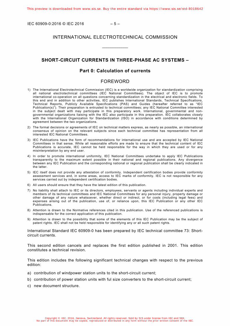
Key
initial symmetrical short-circuit current
ip peak short-circuit current
Ik steady-state short-circuit current
iDC DC component of short-circuit current
A initial value of the DC component iDC
Figure 1 – Short-circuit current of a far-from-generator short circuit with constant AC component (schematic diagram)
In most practical cases a determination like this is not necessary. Depending on the application of the results, it is of interest to know the rms value of the symmetrical AC component and the peak value ip of the short-circuit current following the occurrence of a short circuit. The highest value ip depends on the time constant of the decaying aperiodic component and the frequency f, that is on the ratio R/X or X/R of the short-circuit impedance Zk, and is reached if the short circuit starts at zero voltage. ip also depends on the decay of the symmetrical AC component of the short-circuit current.
In meshed networks there are several direct-current time constants. That is why it is not possible to give an easy method of calculating ip and iDC. Special methods to calculate ip with sufficient accuracy are given in Clause 8.
IEC
This preview is downloaded from www.sis.se. Buy the entire standard via https://www.sis.se/std-8018642
Copyright © IEC, 2016, Geneva, Switzerland. All rights reserved. Sold by SIS under license from IEC and SEK.No part of this document may be copied, reproduced or distributed in any form without the prior written consent of the IEC.