edge.rit.eduedge.rit.edu/content/R13903/public/Steve's Deliverables... · Web viewCost does not...
23
PRP Supplemental Document Table of Contents Benchmarking Table…………………………………………………pg 2 Potential Concepts…………………………………………………...pg 3 PRP Skills Checklist…………………………………………………pg 6 Engineering Analysis……………………………………………...…pg 9 Faculty Support Checklists…………………………………………pg 14 Project Description/ Functional Decomposition... ……………….....pg 17 1
Transcript of edge.rit.eduedge.rit.edu/content/R13903/public/Steve's Deliverables... · Web viewCost does not...
PRP Supplemental DocumentTable of Contents
Benchmarking Table…………………………………………………pg 2Potential Concepts…………………………………………………...pg 3PRP Skills Checklist…………………………………………………pg 6Engineering Analysis……………………………………………...…pg 9Faculty Support Checklists…………………………………………pg 14 Project Description/ Functional Decomposition...……………….....pg 17
1
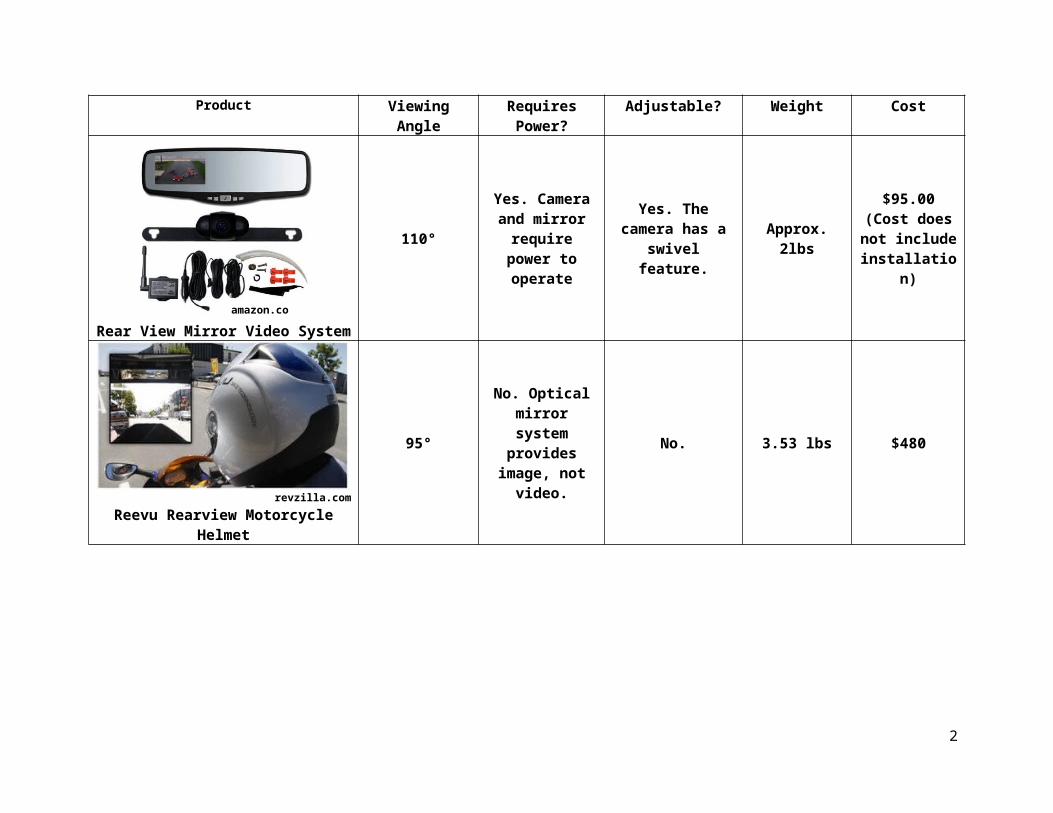
Product Viewing Angle Requires Power? Adjustable? Weight Cost
Rear View Mirror Video System
110°Yes. Camera and
mirror require power to operate
Yes. The camera has a swivel feature. Approx. 2lbs
$95.00 (Cost does not include
installation)
revzilla.comReevu Rearview Motorcycle Helmet
95°No. Optical mirror system provides
image, not video.No. 3.53 lbs $480
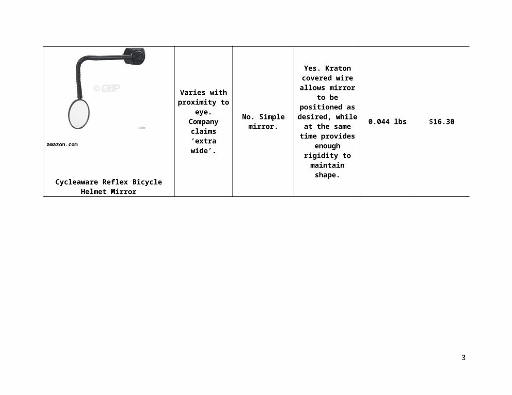
amazon.com
Cycleaware Reflex Bicycle Helmet Mirror
Varies with proximity to eye.Company claims
‘extra wide’.
No. Simple mirror.
Yes. Kraton covered wire allows mirror to be positioned as
desired, while at the same time
provides enough rigidity to maintain
shape.
0.044 lbs $16.30
2
amazon.com
Potential Concepts:
With the project already defined to make use of mirrors, the senior design team would have the most freedom in their path forward in the following areas: (1) mirror attachment method; (2) materials used for mirror and supporting structure; (3) method of supporting mirror; (4) methods for adjusting mirrors; and (5) possibility of moving the forward mirror in and out of the rider’s field of vision.
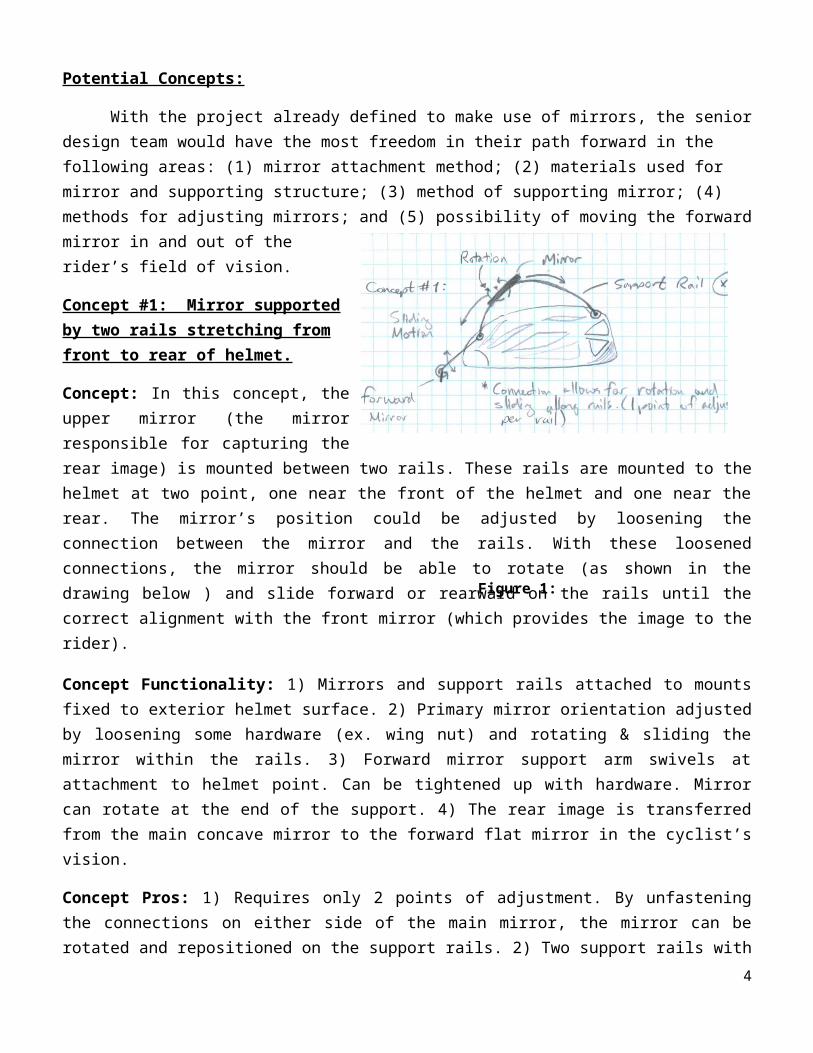
Concept #1: Mirror supported by two rails stretching from front to rear of helmet.
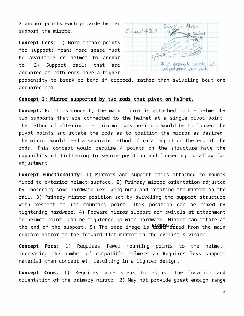
Concept: In this concept, the upper mirror (the mirror responsible for capturing the rear image) is mounted between two rails. These rails are mounted to the helmet at two point, one near the front of the helmet and one near the rear. The mirror’s position could be adjusted by loosening the connection between the mirror and the rails. With these loosened connections, the mirror should be able to rotate (as shown in the drawing below ) and slide forward or rearward on the rails until the correct alignment with the front mirror (which provides the image to the rider).
Concept Functionality: 1) Mirrors and support rails attached to mounts fixed to exterior helmet surface. 2) Primary mirror orientation adjusted by loosening some hardware (ex. wing nut) and rotating & sliding the mirror within the rails. 3) Forward mirror support arm swivels at attachment to helmet point. Can be tightened up with hardware. Mirror can rotate at the end of the support. 4) The rear image is transferred from the main concave mirror to the forward flat mirror in the cyclist’s vision.
Concept Pros: 1) Requires only 2 points of adjustment. By unfastening the connections on either side of the main mirror, the mirror can be rotated and repositioned on the support rails. 2) Two support rails with 2 anchor points each provide better support the mirror.
Concept Cons: 1) More anchor points for supports means more space must be available on helmet to anchor to. 2) Support rails that are anchored at both ends have a higher propensity to break or bend if dropped, rather than swiveling bout one anchored end.
Concept 2: Mirror supported by two rods that pivot on helmet.
Concept: For this concept, the main mirror is attached to the helmet by two supports that are connected to the helmet at a single pivot point. The method of altering the main mirrors position would be to loosen the pivot points and rotate the rods as to position the mirror as desired. The mirror would need a separate method of rotating it on the end of the rods. This concept would require 4 points on the structure have the capability of tightening to secure position and loosening to allow for adjustment.
3
Figure 1: Concept 1
Concept Functionality: 1) Mirrors and support rails attached to mounts fixed to exterior helmet surface. 2) Primary mirror orientation adjusted by loosening some hardware (ex. wing nut) and rotating the mirror on the rail. 3) Primary mirror position set by swiveling the support structure with respect to its mounting point. This position can be fixed by tightening hardware. 4) Forward mirror support arm swivels at attachment to helmet point. Can be tightened up with hardware. Mirror can rotate at the end of the support. 5) The rear image is transferred from the main concave mirror to the forward flat mirror in the cyclist’s vision.
Concept Pros: 1) Requires fewer mounting points to the helmet, increasing the number of compatible helmets 2) Requires less support material than concept #1, resulting in a lighter design.
Concept Cons: 1) Requires more steps to adjust the location and orientation of the primary mirror. 2) May not provide great enough range of motion for primary mirror. The support rails may also need the capability to extend.
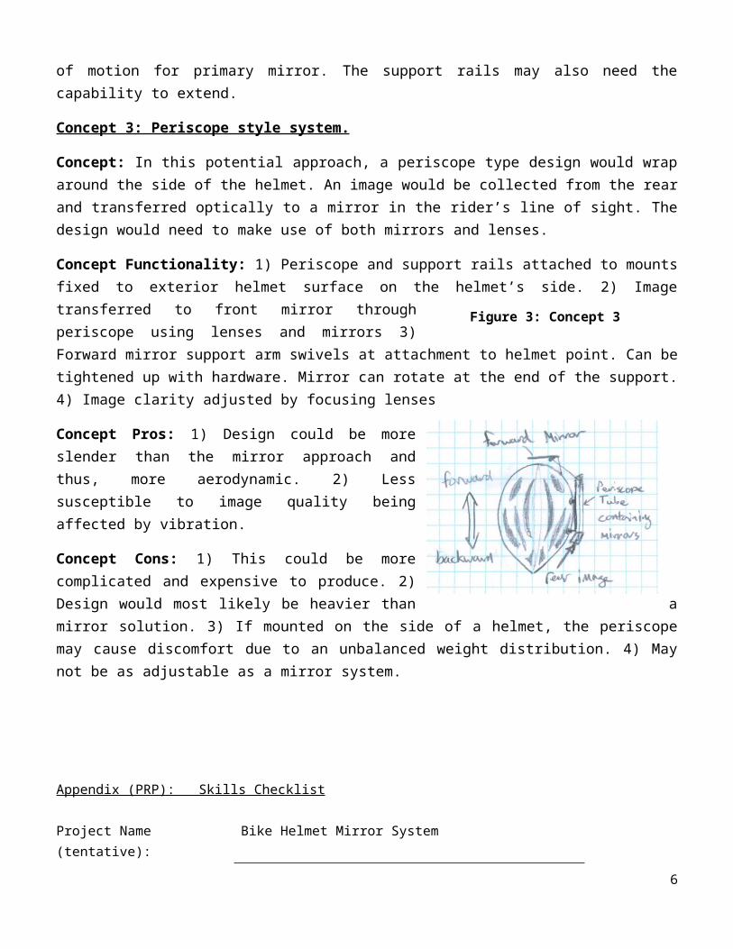
Concept 3: Periscope style system.
Concept: In this potential approach, a periscope type design would wrap around the side of the helmet. An image would be collected from the rear and transferred optically to a mirror in the rider’s line of sight. The design would need to make use of both mirrors and lenses.
Concept Functionality: 1) Periscope and support rails attached to mounts fixed to exterior helmet surface on the helmet’s side. 2) Image transferred to front mirror through periscope using lenses and mirrors 3) Forward mirror support arm swivels at attachment to helmet point. Can be tightened up with hardware. Mirror can rotate at the end of the support. 4) Image clarity adjusted by focusing lenses
Concept Pros: 1) Design could be more slender than the mirror approach and thus, more aerodynamic. 2) Less susceptible to image quality being affected by vibration.
Concept Cons: 1) This could be more complicated and expensive to produce. 2) Design would most likely be heavier than a mirror solution. 3) If mounted on the side of a helmet, the periscope may cause discomfort due to an unbalanced weight distribution. 4) May not be as adjustable as a mirror system.
Appendix (PRP): Skills Checklist4
Figure 2: Concept 2
Figure 3: Concept 3 (periscope style)
Project Name (tentative): Bike Helmet Mirror System
Checklist Completed by (name): Stephen Wess
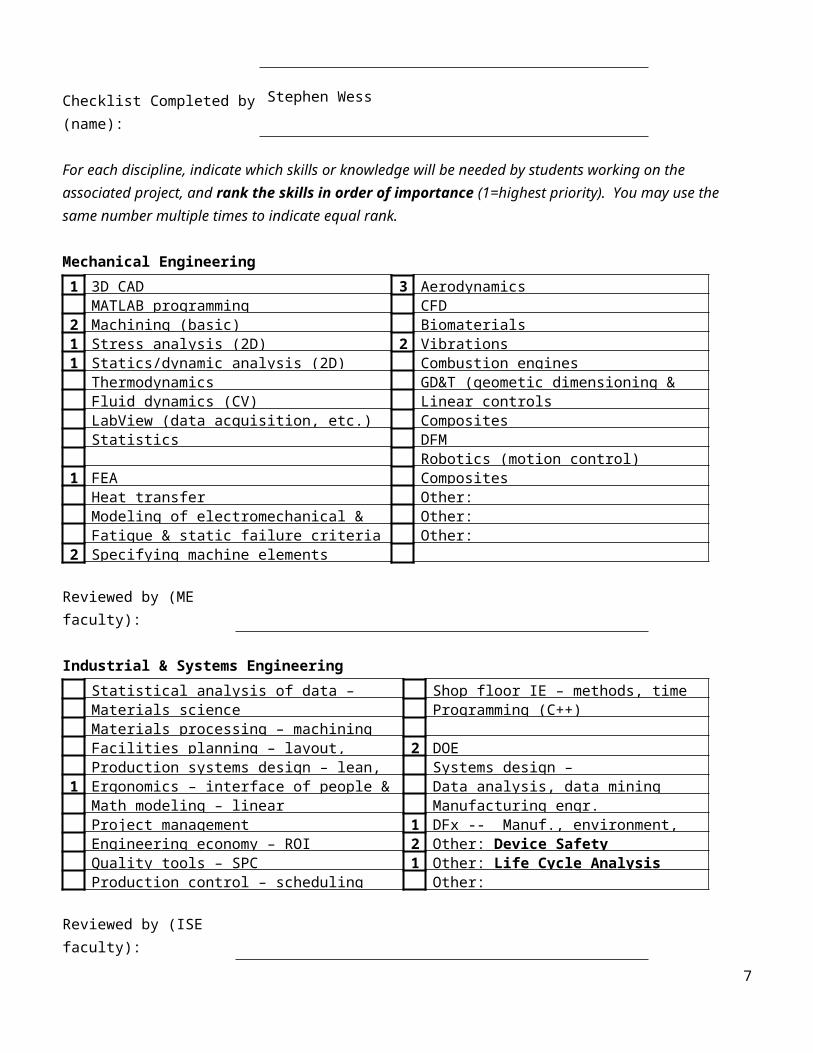
For each discipline, indicate which skills or knowledge will be needed by students working on the associated project, and rank the skills in order of importance (1=highest priority). You may use the same number multiple times to indicate equal rank.
Mechanical Engineering1 3D CAD 3 Aerodynamics
MATLAB programming CFD2 Machining (basic) Biomaterials1 Stress analysis (2D) 2 Vibrations1 Statics/dynamic analysis (2D) Combustion engines
Thermodynamics GD&T (geometic dimensioning & tolerancing)Fluid dynamics (CV) Linear controlsLabView (data acquisition, etc.) CompositesStatistics DFM
Robotics (motion control)1 FEA Composites
Heat transfer Other:Modeling of electromechanical & fluid systems Other:Fatigue & static failure criteria (DME) Other:
2 Specifying machine elements
Reviewed by (ME faculty):
Industrial & Systems EngineeringStatistical analysis of data – regression Shop floor IE – methods, time studyMaterials science Programming (C++)Materials processing – machining labFacilities planning – layout, material handling 2 DOEProduction systems design – lean, process Systems design – product/process design
1 Ergonomics – interface of people & equipment Data analysis, data miningMath modeling – linear programming), simulation Manufacturing engr.Project management 1 DFx -- Manuf., environment, sustainabilityEngineering economy – ROI 2 Other: Device SafetyQuality tools – SPC 1 Other: Life Cycle AnalysisProduction control – scheduling Other:
Reviewed by (ISE faculty):
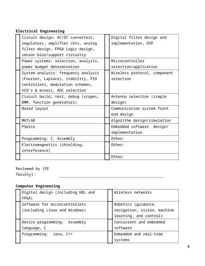
Electrical Engineering
5
Circuit design: AC/DC converters, regulators, amplifier ckts, analog filter design, FPGA Logic design, sensor bias/support circuitry
Digital filter design and implementation, DSP
Power systems: selection, analysis, power budget determination
Microcontroller selection/application
System analysis: frequency analysis (Fourier, Laplace), stability, PID controllers, modulation schemes, VCO’s & mixers, ADC selection
Wireless protocol, component selection
Circuit build, test, debug (scopes, DMM, function generators)
Antenna selection (simple design)
Board layout Communication system front end designMATLAB Algorithm design/simulationPSpice Embedded software design/
implementationProgramming: C, Assembly Other: Electromagnetics (shielding, interference) Other:
Other:
Reviewed by (EE faculty):
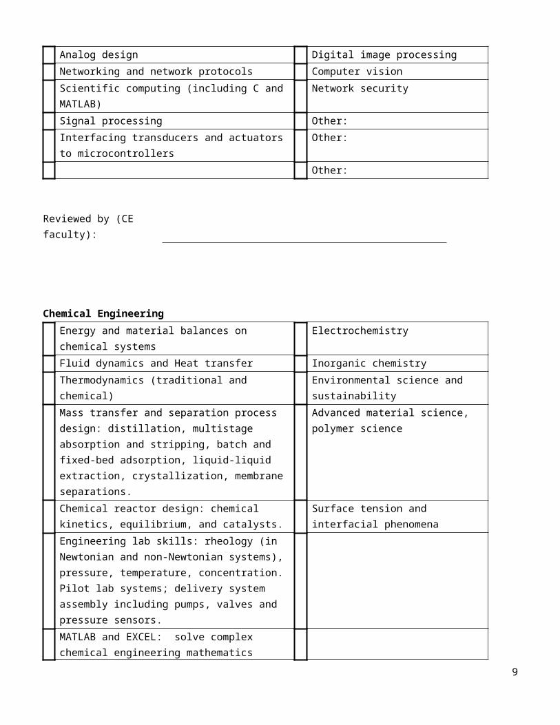
Computer EngineeringDigital design (including HDL and FPGA) Wireless networksSoftware for microcontrollers (including Linux and Windows)
Robotics (guidance, navigation, vision, machine learning, and control)
Device programming: Assembly language, C Concurrent and embedded softwareProgramming: Java, C++ Embedded and real-time systemsAnalog design Digital image processingNetworking and network protocols Computer visionScientific computing (including C and MATLAB) Network securitySignal processing Other: Interfacing transducers and actuators to microcontrollers
Other:
Other:
Reviewed by (CE faculty):
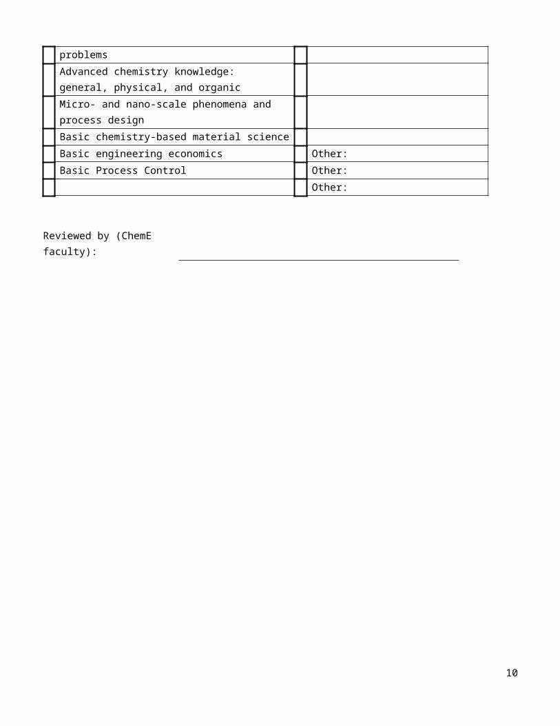
Chemical Engineering
6
Energy and material balances on chemical systems ElectrochemistryFluid dynamics and Heat transfer Inorganic chemistryThermodynamics (traditional and chemical) Environmental science and sustainabilityMass transfer and separation process design: distillation, multistage absorption and stripping, batch and fixed-bed adsorption, liquid-liquid extraction, crystallization, membrane separations.
Advanced material science, polymer science
Chemical reactor design: chemical kinetics, equilibrium, and catalysts.
Surface tension and interfacial phenomena
Engineering lab skills: rheology (in Newtonian and non-Newtonian systems), pressure, temperature, concentration. Pilot lab systems; delivery system assembly including pumps, valves and pressure sensors.MATLAB and EXCEL: solve complex chemical engineering mathematics problemsAdvanced chemistry knowledge: general, physical, and organicMicro- and nano-scale phenomena and process design Basic chemistry-based material scienceBasic engineering economics Other:Basic Process Control Other:
Other:
Reviewed by (ChemE faculty):
7
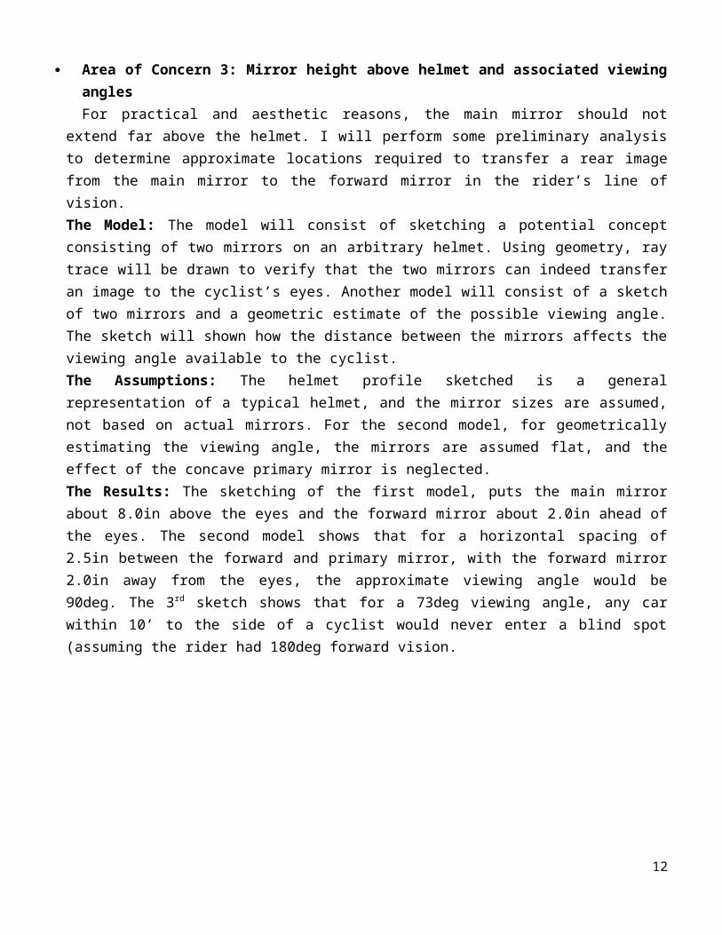
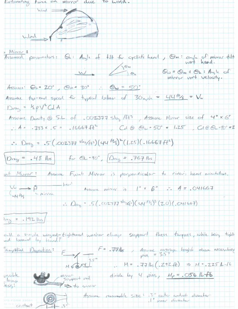
Engineering Analysis: For several keys areas of concern, models have been generated to determine the feasibility of potential solutions. Below, these models are briefly described. The implementation of the models has also been included in the form of scanned handwritten work on the following pages. Area of Concern 1: Mirror support rails pivot point resistance to motion
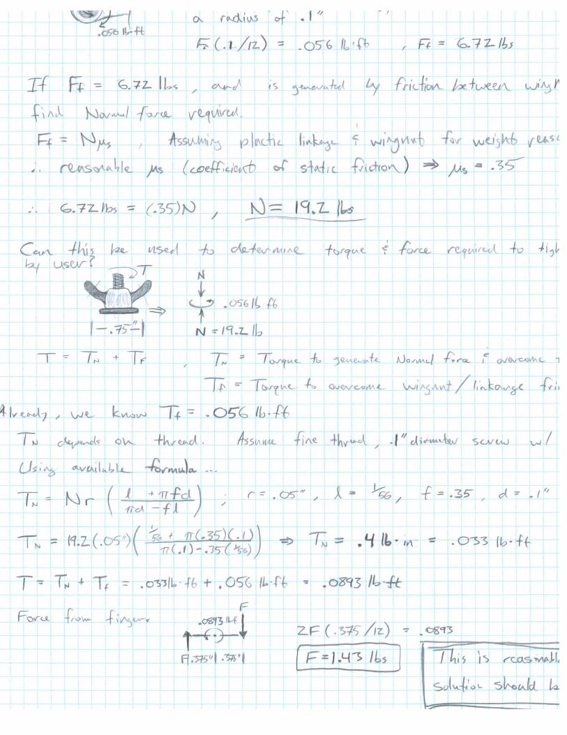
Once the mirrors are adjusted by the user, they must maintain their position or else the view for the cyclist will be undesirable. This means that the support structure must prevent the mirror from moving in the presence of wind resistance. The goal of the model is to determine the necessary forces and whether or not a person will be able to generate these forces by tightening a wing nut by hand.The Model: A mathematical power screw analysis from Shigley’s “Mechanical Engineering Design”.The Assumptions: Standard size threads were assumed. The material was modeled as plastic. Drag on the system will be determined assuming ideal flow. All dimensions were assumed for the potential solution. For specific values that were assumed, see the scanned in page.The Results: After working through the mathematical model, it was determined that a force of 1.43lbs must be input on the wing nut by the user. This is a reasonable number for a person to be capable of applying.
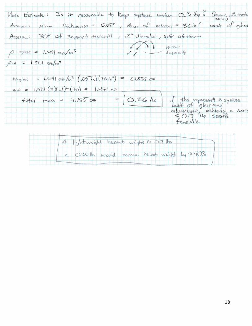
Area of Concern 2: Mass estimationThe mirror system will be undesirable to consumers if it is uncomfortably heavy when placed on the user’s
head. Investigating material properties and coming up with an initial, structurally conservative design will allow one to estimate an upper bound on the system mass. The Model: The mass will be estimated by assuming an upper bound on the solution. The support rails will be modeled as solid aluminum, and the mirrors will be assumed to have a relatively large area. For specific dimensions assumed see the scanned in analysis page. The Assumptions: All the dimensions were assumed to represent an overdesigned design solution. Density of mirror material was assumed to be equal to that of glass.The Results: The results for the over-designed assumptions showed a mass estimation of 0.26lbs. This is less than the marginal spec of 0.3lbs, therefore is should be feasible to produce a system weighing less than this, meeting the customer’s need. For a typical helmet, this is a 40% increase in mass.
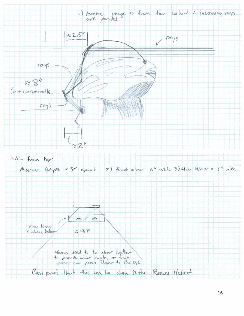
Area of Concern 3: Mirror height above helmet and associated viewing anglesFor practical and aesthetic reasons, the main mirror should not extend far above the helmet. I will
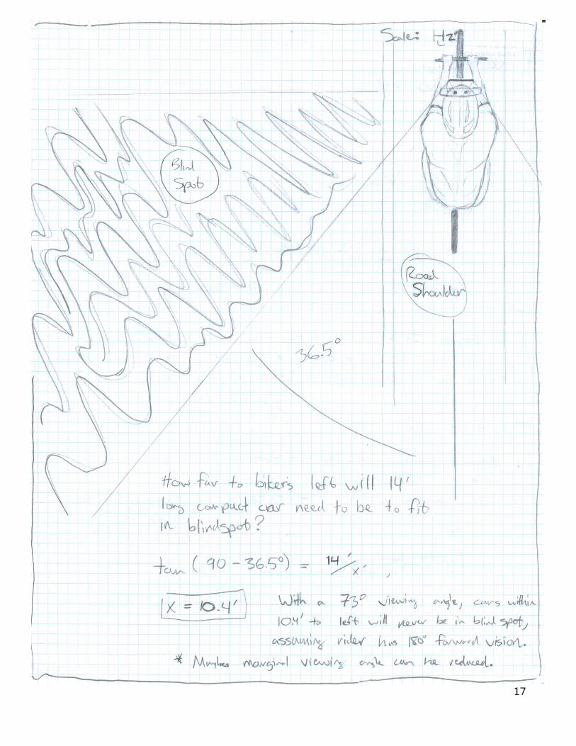
perform some preliminary analysis to determine approximate locations required to transfer a rear image from the main mirror to the forward mirror in the rider’s line of vision. The Model: The model will consist of sketching a potential concept consisting of two mirrors on an arbitrary helmet. Using geometry, ray trace will be drawn to verify that the two mirrors can indeed transfer an image to the cyclist’s eyes. Another model will consist of a sketch of two mirrors and a geometric estimate of the possible viewing angle. The sketch will shown how the distance between the mirrors affects the viewing angle available to the cyclist.The Assumptions: The helmet profile sketched is a general representation of a typical helmet, and the mirror sizes are assumed, not based on actual mirrors. For the second model, for geometrically estimating the viewing angle, the mirrors are assumed flat, and the effect of the concave primary mirror is neglected.The Results: The sketching of the first model, puts the main mirror about 8.0in above the eyes and the forward mirror about 2.0in ahead of the eyes. The second model shows that for a horizontal spacing of 2.5in between the forward and primary mirror, with the forward mirror 2.0in away from the eyes, the approximate viewing angle would be 90deg. The 3rd sketch shows that for a 73deg viewing angle, any car within 10’ to the side of a cyclist would never enter a blind spot (assuming the rider had 180deg forward vision.
8
9
10
11
12
13

14
15
16
17
Bike Helmet Mirror System
MSDI: Winter (AY 2012) MSDII: Spring (AY 2012)
Project Description: A two-mirror system that attaches to a cyclist’s helmet had been proposed by Rob Fish, an RIT industrial design student. A senior design team will be tasked to design and test a helmet based mirror system that improves upon mirror systems currently available. The senior design team will work in conjunction with Rob Fish to refine the existing concept and deliver a product that meets the needs of the average cyclist.
Design emphasis will be placed on minimizing the mirror’s obstruction of the cyclist’s forward vision, providing a clear, wide angle image, and producing a versatile system that can mount on various helmets without compromising the integrity of the helmet. Furthermore, a strong emphasis will be placed on the design for manufacture aspect of the product in an attempt to reduce the cost of materials and thus the cost to the consumer. Ultimately, the focus of the project will be to deliver a mature, polished final product that is inexpensive, easily adjusted, and can be installed on most bike helmets on the shelf today.
MSD Team: Mechanical Engineer (x2); Industrial Systems Engineer (x1); Industrial Designer (x1)Customer – Groups: Leisure Cyclists, Commuter Cyclists Customer – Specific: Sharief B’dour – Bert’s Bike Associate (tentative)Stakeholders: Leisure cyclists, commuter cyclists, bike retailers, parents of child cyclists, bike safety
activists, current product competitors, manufacturersFaculty Consultants: Primary: Dr. M. Gomes (ME) Technical Support: Dr. M. Marshall (ISE), Dr. M. Lam
(ME), & Dr. D. Cormier (ISE)
Feasibility: A highlight of this project is that it will give the SD team an opportunity to take a pre-existing concept and turn it into a polished product. One of the technical challenges will be to design an attachment method that is easily adjusted, yet be able to withstand wind forces and vibrations without moving and compromising the image quality. Several helmet mirrors are available on the market today. Therefore, we know the technology is present to ensure that this project is feasible.
18
Figure 1: Preliminary Concept by Rob Fish
Figure 2: Functional Decomposition of Current Prototype
19