EDCO Single-Disc Grinder - The Home Depot 4 SINGLE DISC GRINDER Operational Keys to good machine...
20
Tool Rental Center MANUAL EDCO Single-Disc Grinder 50200-HD-11.13
-
Upload
hoangkhanh -
Category
Documents
-
view
217 -
download
0
Transcript of EDCO Single-Disc Grinder - The Home Depot 4 SINGLE DISC GRINDER Operational Keys to good machine...

Page 1
Tool Rental CenterMANUAL
EDCOSingle-Disc
Grinder
Reorder Part # HDTR-SEC-TM Class # 298550200-HD-11.13

Page 2
READ AND UNDERSTAND THE OPERATORS INSTRUCTION MANUAL THOROUGHLY BEFORE ATTEMPTING TO OPERATE THIS EQUIPMENT.
Death or serious injury could occur if this machine is used improperly.
Extreme care must be taken when operating electric models with water present: Ensure power cord is prop-erly grounded, is attached to a Ground-Fault-Interrupter (GFI) outlet, and is undamaged.
• Check all electrical cables - be sure connections are tight and cable is continuous and in good condition. Be sure cable is
correctly rated for both the operating current and voltage of this equipment.
• Improper connection of the equipment-grounding conductor can result in a risk of electric shock. Check with qualified electri-
cian or service person if there is any doubt as to whether the outlet is properly grounded. Adhere to all local codes and
ordinances.• NOTE: In the event of a malfunction or breakdown, grounding
provides a path of least resistance for the electric current to dissipate. The motor is equipped with a grounded plug and must be connected to an outlet that is properly installed and properly grounded. DO NOT modify the plug provided on the motor. If the plug does not fit the outlet have a qualified electri-cian install the proper receptacle.
• Switch motor OFF before disconnecting power.
• Engine exhaust from this product contains chemicals known to the State of California to cause cancer, birth defects or other reproduc-tive harm.
• Gasoline is extremely flammable and poisonous. It should only be dispensed in well ventilated areas, and with a cool engine.
• Small gasoline engines produce high concentra- tions of carbon monoxide (CO) example: a 5 HP 4 cycle engine operation in an enclosed 100,000 cu. ft. area with only one change of air per hour is capable of providing deadly concentrations of CO in less than fifteen minutes. Five changes of air in the same area will produce noxious fumes in less than 30 minutes. Gasoline or propane pow- ered equipment should not be used in enclosed or partially enclosed areas. Symptoms of CO poisoning include, head- ache, nausea, weakness, dizziness, visual problems and loss of consciousness. If symptoms occur - get into fresh air and seek medical attention immediately.
SAFETY MESSAGES
SAFETY MESSAGES
Indicates an imminent hazard which, if not avoided, will result in death or serious injury. Indicates an imminent hazard which, if not avoided, can result in death or serious injury. Indicates hazards which, if not avoided, could result in serious injury and or damage to the equipment.
• Safety Instructions are proceeded by a graphic alert symbol of DANGER, WARNING, or CAUTION.
ELECTRICAL POWERED EQUIPMENT
GASOLINE/PROPANE POWERED EQUIPMENT
• Equipment should only be operated by trained personnel in good physical condition and mental health (not fatigued). The operator and maintenance personnel must be physically able to handle the bulk weight and power of this equipment.
• This is a one person tool. Maintain a safe operating distance to other personnel. It is the operators’ responsibility to keep other people (workers, pedestrians, bystanders, etc.) away during operation. Block off the work area in all directions with roping, safety netting, etc. for a safe distance. Failure to do so may result in others being injured by flying debris or exposing them to harmful dust and noise.
• This equipment is intended for commercial use only. • For the operator’s safety and the safety of others, always keep
all guards in place during operation.• Never let equipment run unattended.
• Personal Protection Equipment and proper safety attire must be worn when operating this machinery. The operator must wear approved safety equipment appropriate for the job such as hard hat and safety shoes when conditions require. Hear-ing protection MUST be used (operational noise levels of this equipment may exceed 85db). Eye protection MUST be worn at all times.
Keep body parts and loose clothing away from moving parts. Failure to do so could result in dismemberment or death.
• Do not modify the machine. • Stop motor/engine when adjusting or servicing this equipment.
Maintain a safe operating distance from flammable materials. Sparks from the cutting-action of this machine can ignite flammable materials or vapors.
GENERAL INSTRUCTIONS
DUST WARNING
Some dust created by power sanding, sawing, grinding, drilling, and other construction activi-ties contains chemicals known to cause cancer, birth defects, or other reproductive harm. Some examples of these chemicals are:
• Lead from lead-based paints, and • Crystalline silica from bricks and concrete and other masonry products. Your risk of exposure to these chemicals varies depending
on how often you do this type of work. To reduce your risk: work in a well ventilated area, use a dust control system, such as an industrial-style vacuum, and wear approved personal safety equipment, such as a dust/particle respirator designed to filter out microscopic particles.
• Do not disconnect power by pulling cord. To disconnect, grasp the plug, not the cord.
• Unplug power cord at the machine when not in use and before servicing.

Page 3
TOOL RENTAL CENTER MANUAL
SINGLE-DISC CONCRETE FLOOR GRINDER
Section Page Number
Safety Messages and General Instructions . . . . . . . . . . . . . . . . . . . . . . . . . . . . . . . . . . . . 2How To Order Replacement Parts . . . . . . . . . . . . . . . . . . . . . . . . . . . . . . . . . . . . . . . . . . . 3Operational Keys . . . . . . . . . . . . . . . . . . . . . . . . . . . . . . . . . . . . . . . . . . . . . . . . . . . . . . . . 4Troubleshooting and Servicing . . . . . . . . . . . . . . . . . . . . . . . . . . . . . . . . . . . . . . . . . . . . . . 5Important Notes . . . . . . . . . . . . . . . . . . . . . . . . . . . . . . . . . . . . . . . . . . . . . . . . . . . . . . . . . 6, 7Lubricating Flange Bearings and Attaching a Vacuum . . . . . . . . . . . . . . . . . . . . . . . . . . . 8Procedure for Adjusting and replacing Belt . . . . . . . . . . . . . . . . . . . . . . . . . . . . . . . . . . . . 9Illustration 1: Main Grouping . . . . . . . . . . . . . . . . . . . . . . . . . . . . . . . . . . . . . . . . . . . . . . . 10, 11Illustration 2: Water Valve Grouping . . . . . . . . . . . . . . . . . . . . . . . . . . . . . . . . . . . . . . . . . 12Illustration 3: Head Assembly . . . . . . . . . . . . . . . . . . . . . . . . . . . . . . . . . . . . . . . . . . . . . . 13Illustration 4: Motor & Belt Drive Grouping . . . . . . . . . . . . . . . . . . . . . . . . . . . . . . . . . . . . 14, 15Switch Wiring Diagram . . . . . . . . . . . . . . . . . . . . . . . . . . . . . . . . . . . . . . . . . . . . . . . . . . . . 16Motor Wiring Diagram . . . . . . . . . . . . . . . . . . . . . . . . . . . . . . . . . . . . . . . . . . . . . . . . . . . . . 17Maintenance Schedule . . . . . . . . . . . . . . . . . . . . . . . . . . . . . . . . . . . . . . . . . . . . . . . . . . . . 18Notes: Equipment Repairs . . . . . . . . . . . . . . . . . . . . . . . . . . . . . . . . . . . . . . . . . . . . . . . . . 19
HOW TO ORDER REPLACEMENT PARTS
To insure product safety and reliability, always use genuine EDCO replacement parts when making repairs to the equipment.
When calling for parts, specify the MODEL and SERIAL number of the machine, which can be found on the NAME PLATE. Keep that information in the space provided. In addition to this information, give part number, description, and quantity as listed on the parts list to your parts representative.
Please note: Due to improvements and changes in the equipment, the illustrations shown may be different than the actual machine.
FILL IN INFORMATION BELOW
Date of Purchase ______________________________
Model # _____________________________________
Serial # ______________________________________
SKU # ______________________________________
TABLE OF CONTENTS

Page 4
SINGLE DISC GRINDER
Operational Keys to good machine care and long life...
1. Before each use, check and insure all hardware, nuts, bolts and fittings are tight and not worn or damaged. If damaged or missing hardware is noted, it should be replaced before the machine is put back into service.
2. If using attachments such as a vacuum for dust control, insure filters are clean and the vacuum is empty before each use and empty often for best vacuum performance. Check hoses, gaskets, seals and filters for damage. If any damage is found the part or parts should be replaced. Dirty or damaged filters and leaking gaskets or seals will cause poor vacuum performance, penetrate and shorten the life of any motor and cause uncontrollable dust which is hazardous to ones health.
3. Check the maintenance schedule for important information about lubrication intervals. Remember, machines used in a dusty environment have a more frequent lubrication requirement than a machine that is not used in a dusty environment.
4. Machines that have electric motors should be checked for proper voltage settings by checking the name plate on the motor for the different electrical configurations i.e.: single phase, three phase and the voltage settings available. This is not required on single voltage motors i.e.: 120 Volt Single Phase. The power cords and/or extension cords should be checked for proper length and gauge, remember, the longer the cord a heavier gauge wire is required. Too small a gauge wire causes a voltage drop which in turn causes motor overheating and damage. Check all wiring for cuts, bare or ex-posed wire and damaged connectors or plugs. These items can cause fatal shocks under the right conditions. It is current that kills, not voltage.
5. After each days use, the machine should be cleaned. When cleaning electric powered machines, cover any openings to prevent contaminants from entering the motor.
MODEL SEC-HD
Page 5
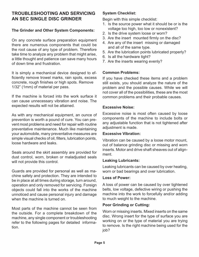
TROUBLESHOOTING AND SERVICINGAN SEC SINGLE DISC GRINDER
The Grinder and Other System Components:
On any concrete surface preparation equipment there are numerous components that could be the root cause of any type of problem. Therefore take time to analyze any problem that might arise, a little thought and patience can save many hours of down time and frustration.
It is simply a mechanical device designed to ef-ficiently remove trowel marks, rain spots, excess concrete, rough finishes or high spots. Remove 1/32” (1mm) of material per pass.
If the machine is forced into the work surface it can cause unnecessary vibration and noise. The expected results will not be attained.
As with any mechanical equipment, an ounce of prevention is worth a pound of cure. You can pre-vent most problems and need for repair with routine preventative maintenance. Much like maintaining your automobile, many preventative measures are simple visual checks of oil, filters, lubrication points, loose hardware and leaks.
Seals around the skirt assembly are provided for dust control, worn, broken or maladjusted seals will not provide this control.
Guards are provided for personal as well as ma-chine safety and protection. They are intended to be in place at all times during storage, turn around, operation and only removed for servicing. Foreign objects could fall into the works of the machine unnoticed and cause personal injury and damage when the machine is turned on.
Most parts of the machine cannot be seen from the outside. For a complete breakdown of the machine, any single component or troubleshooting refer to the following pages for detailed informa-tion.
System Checklist:Begin with this simple checklist:1. Is the source power what it should be or is the voltage too high, too low or nonexistent?2. Is the drive system loose or worn?3. Are the insert mounted firmly on the disc?4. Are any of the insert missing or damaged and all of the same type.5. Are the lubrication points lubricated properly?6. Is all the hardware tight?7. Are the inserts wearing evenly?
Common Problems:If you have checked these items and a problem still exists, you should analyze the nature of the problem and the possible causes. While we will not cover all of the possibilities, these are the most common problems and their probable causes.
Excessive Noise:Excessive noise is most often caused by loose components of the machine to include bolts or any adjustable function that is not tightened after adjustment is made. Excessive Vibration:Vibration can be caused by a loose motor mount,out of balance grinding disc or missing and worn inserts. Motor and drive shaft sheaves out of align-ment.Leaking Lubricants:Leaking lubricants can be caused by over heating, worn or bad bearings and over lubrication. Loss of Power:
A loss of power can be caused by over tightened belts, low voltage, defective wiring or pushing the machine into the work to forcefully and/or adding to much weight to the machine. Poor Grinding or Cutting:Worn or missing inserts. Mixed inserts on the same disc. Wrong insert for the type of surface you are working on or the type of material you are trying to remove. Is the right machine being used for the job?

Page 6
NOTE:This is the lifting bail for this machine.
NOTE:This is not a lifting bail for this machine.
NOTE:Motor overload reset on bottom of box.
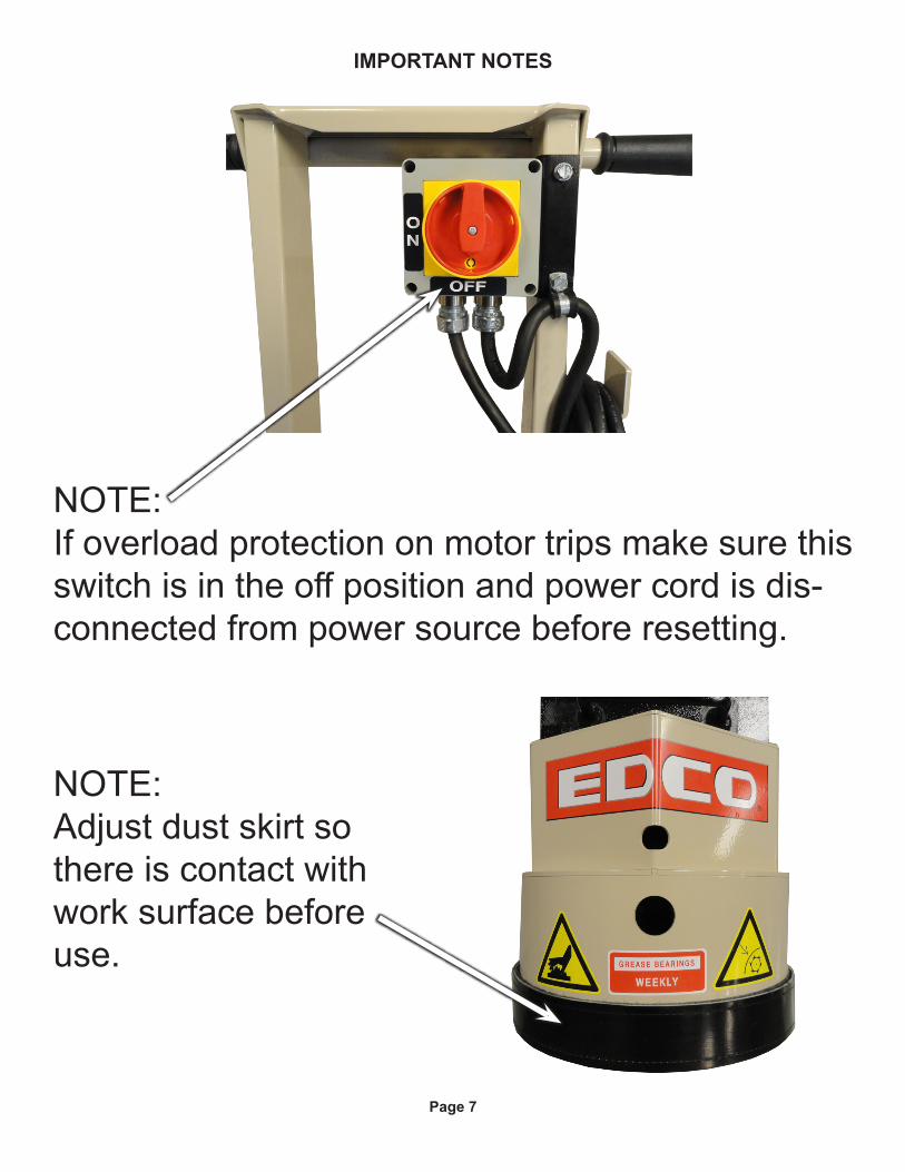
IMPORTANT NOTES
Page 7
NOTE:Adjust dust skirt so there is contact with work surface before use.
NOTE:If overload protection on motor trips make sure this switch is in the off position and power cord is dis-connected from power source before resetting.
IMPORTANT NOTES

Page 8
PROCEDURE FOR LUBRICATING FLANGE BEARINGS
To grease the flange bearings attach the grease gun to the grease fittings as shown in the above photos and give only two (2) pumps on the grease gun weekly. If excessive over lubrication is done grease will leak onto the work surface causing possible damage and wasted cleanup time.
If using a vacuum for dust control attach it to the vacuum port located on the rear of the handle securing it as shown in photo above.
PROCEDURE FOR ATTACHING A VACUUM
WaterHook-up
VacuumHook-up

Page 9
PROCEDURE FOR ADJUSTING OR REPLACING DRIVE BELT
To adjust the drive belt loosen four (4) bolts securing the motor mount to the frame.
Slide the motor mount to the rear of the machine to increase belt tension.
Tighten the four (4) bolts loosened earlier maintaining pressure on the motor mount to prevent loosening.
To replace the belt, remove the hood by removing two (2) bolts, one on each side of the machine.
Loosen the four (4) bolts as in the first step and slide the motor mount all the way forward.
Remove the belt from the motor and driven shaft sheaves as shown in the photo on the left.
Reverse the previous step to install new belt. Slide mo-tor mount towards the rear of the machine and adjust belt tension, tighten all four (4) bolts as explained above. Replace hood and tighten bolts.
NOTE:While cover is removed check to see if there are any remnants of grease from servicing on any of the sur-faces, remove and dispose of properly.

Page 10
ILLUSTRATION 1: MAIN GROUPING

Page 11
PARTS LISTING - ILLUSTRATION 1 : MAIN GROUPINGITEM # PART # DESCRIPTION QTY.
1 86401 MAIN FRAME 12 28003 WHEEL 10 X 2-1/4 X 3/4”BRG 23 10009 WASHER, FLAT 3/4 SAE ZINC 44 10428 COLLAR, LOCKING 3/4”ID 25 86426K RUBBER SKIRT W/ VELCRO LOOP & HOOK
(INCLUDES ITEMS 6 & 7 TOGETHER)1
6 86426 RUBBER SKIRT W/ VELCRO-LOOP ONLY, 2 X 39-1/8(THESE 2 PIECES ARE SEWN TOGETHER)
1
7 86427 VELCRO-HOOK ONLY, 1” X 37-1/2”, SEC(THIS PIECE IS PLACED AROUND THE BOTTOM EDGE OF THE SHROUD)
1
8 10907 SCREW, CAP 3/8-16 X 3/4 29 10811 WASHER, LOCK 3/8 ZINC 210 10025 WASHER, FLAT 3/8 SAE ZINC 211 86402 HOOD, SEC 112 86345H WEIGHT BLOCK W/ HANDLE, 30 LB. 113 10323T T-SCREW 1/2-13 X 2-1/2 214 10312 WASHER, FLAT 1/2 SAE ZINC 215 86304S HANDLE BAR, SEC 116 10608 GRIP, HAND 1” MODEL AT 217 10029 SCREW, CAP 3/8-24 X 1-3/4 418 10025 WASHER, FLAT 3/8 SAE ZINC 819 10004 NUT, HEX LOCK 3/8-24 ZINC 420 86419 HOLDER, POWER CORD 121 10846 SCREW, CAP STSHW 1/4-20 X 1/2 222 10038 WASHER, LOCK 1/4 ZINC 223 86347 BRACKET, MULTI-VAC PORT 2-3” 124 10846 SCREW, CAP STSHW 1/4-20 X 1/2 225 10038 WASHER, LOCK 1/4 ZINC 226 65021 CAP/PLUG 2” RED PLASTIC, FLANGED 127 77113 HOSE, FLEX 2”ID X 32”L 128 10766 CLAMP, HOSE, SAE #32, ADJ. TO 2-1/2 229 77008 BEARING, BALL 1” 4-HOLE FLANGE, ND 230 10003 SCREW, CAP 7/16-20 X 1-1/4 ZINC 831 10450 WASHER, LOCK 7/16 ZINC 832 10481 NUT, HEX 7/16-20 ZINC 833 86432 SPACER, SEC-HD 1”ID X 1-1/2”OD X 2-1/8”L 134 86433 HEAD ASSEMBLY, SEC-HD (REFER TO ILLUS. 3 FOR BREAKDOWN) 135 19166 DIAMOND DISC, ECONOMY 10” - 20 SEG. 136 86108 SCREW, FLAT HD SKT 3/8-24 X 3/4 4

Page 12
ITEM # PART # DESCRIPTION QTY.1 80021 CONN., SWIVEL FEM. 3/4HOSE X 1/2MPT
(INCLUDES HOSE WASHER)1
2 10711 VALVE, BALL 1/2 FPT 13 50075 BARB, 3/8 HOSE X 1/4MPT (BRASS) 14 50069 CLAMP, HOSE, SAE #6, ADJ. TO 13/16 25 86424 HOSE 3/8”ID X 20”L 16 11562 BARB ELBOW 90, 3/8HOSE X 1/8MPT (BRASS) 17 10864 NUT 1/8-27 PIPE THREAD (BRASS) 1
ILLUSTRATION 2: WATER VALVE GROUPING

Page 13
ITEM # PART # DESCRIPTION QTY.1-12 86433 HEAD ASSEMBLY (INCLUDES ITEMS 1 THRU 12) 1
1 86393 SHAFT, SEC-HD 1”DIA. X 9-11/16”L 12 10063 PIN, ROLL 3/8 X 2 13 77020 RING, HUB CARRIER, 6-HOLE 14 10112 RING, RUBBER, 4-1/2”OD X 1/2”THK 25 77010 HUB, ALUMINUM 6-HOLE (GRINDER) 16 86431 MOUNTING DISC, DIAMOND HEAD, SEC-HD 17 10354 SCREW, SKT. HD. CAP 3/8-24 X 1-3/4 38 10012 SCREW, SKT. HD. CAP 3/8-24 X 2 39 10113 SPACER, STEEL 9/16OD X 3/8ID X 7/32 3
10 10011 SPACER, STEEL 5/8OD X 3/8ID X 3/8T 611 10014 NUT, HEX 3/8-24 ZINC (USE RED LOCTITE) 312 11725 NUT, HEX JAM 3/8-24 ZINC (USE RED LOCTITE) 3
ILLUSTRATION 3: HEAD ASSEMBLY

Page 14
ILLUSTRATION 4: MOTOR & BELT DRIVE GROUPING

Page 15
PARTS LISTING - ILLUSTRATION 4: MOTOR & BELT DRIVE GROUPING ITEM # PART # DESCRIPTION QTY.
1 16077
16178..... 16174..... 16179.....
MOTOR, 1.5HP-1PH-60HZ-1725RPM-115/230V-13/6.5ALEESON CAT. NO. 113769.00 REPLACEMENT PARTS:.....CAPACITOR, START, LEESON 003025.15 (500MFD 125V).....CAPACITOR, RUN, LEESON 003014.02 (50MFD 240V).....RESET BUTTON, LEESON 300033.02 (CED2705)
1
111
2 86404 MOUNT, MOTOR 13 10806 SCREW, CAP 5/16-18 X 1 44 10213 WASHER, FLAT 5/16 SAE ZINC 45 10801 WASHER, LOCK 5/16 ZINC 46 10054 NUT, HEX 5/16-18 ZINC 47 10055 SCREW, CAP 3/8-16 X 1 48 10811 WASHER, LOCK 3/8 ZINC 49 10025 WASHER, FLAT 3/8 SAE ZINC 410 3613 SHEAVE 3”OD X 1GR.B X 5/8”BORE 111 ----- KEY 3/16”SQ. X 1-3/8 (INCLUDED W/ MOTOR) 112 10277 BELT B-38 113 86009 SHEAVE 9” OD X 1GR.B X 1” BORE 114 40317 KEY 1/4SQ X 1-5/8 115 77042 BRACKET, LOVATO ROTARY CAM SWITCH 116 10846 SCREW, CAP STSHW 1/4-20 X 1/2 217 10038 WASHER, LOCK 1/4 ZINC 218 11663 SCREW, MACHINE 8-32 X 1/2 RHCD ZINC 419 10462 NUT, KEPS LOCK 8-32 ZINC 420 77043
77043-2..... 77043-4.....
SWITCH, ROTARY CAM ON/OFF, LOVATO REPLACEMENT PARTS:.....SWITCH HANDLE, PADLOCKABLE, LOVATO.....GASKET RING, OPERATOR, LOVATO
1
11
21 77043-1 SWITCH ADAPTER, PG16 TO 1/2”NPT (INCLUDED W/ SWITCH) 222 40066 STRAIN RELIEF 1/2NPT X .350-.450” 223 11690 CLAMP, LOOM, 3/8” 124 77045 WIRE HARNESS 12/3 X 42”LOA 125 16176 STRAIN RELIEF 3/4NPT X .350-.450” 126 10740 CONDUIT LOCK NUT 3/4 NP (LOCATED INSIDE JUNCTION BOX) 127 10982 TIE, CABLE, BLACK NYLON 11-1/4” 228 86422 CORD W/ PLUG, 25FT. POWER, STRAIGHT STYLE PLUG 1

Page 16
SWITCH WIRING DIAGRAM

Page 17
LEESON CAT. NO. 113769.001.5HP 60Hz SINGLE PHASE
USE CONNECTIONS FOR CLOCK-WISE (C.W.) ROTATION SHOWN BELOW IN CHARTPOWER CORD: BLACK WIRE - L1, WHITE WIRE - L2, GREEN WIRE - GROUND
LOW VOLT (115V) STANDARD, HIGH VOLT (230V) OPTIONAL
REPLACEMENT PARTS:START CAPACITOR: PART # 16178 LEESON 003025.15 500MFD 125VRUN CAPACITOR: PART # 16174 LEESON 003014.02 50MFD 240VTHERMAL PROTECTOR: PART # 16179 RESET BUTTON CED2705, LEESON 300033.02
MOTOR WIRING DIAGRAM

Page 18
Repairs are to be done by authorized EDCO Dealers only.
Read and follow instruc-tions in the motor owner’s manual.
Maintenance Schedule
Bef
ore
Ope
ratio
n
As
Req
uire
d
Eve
ry 5
0 H
ours
of O
pera
tion
Dai
ly
X
X
X
All maintenance to be performed by
qualified personnel. E
very
Dis
cC
hang
e
Visual Inspection of Entire Machine
Check accessoriesfor uneven wear
X
X
X
X
Grease Flange Bearings
Clean Dust & Dirt Off Machine
Check Disc Shaftand bearings
Replace Disc
Belt Tensioning

Page 19
Record here any repairs or changes made to the Equipment
NOTES

Page 20 SEC.TM.4.0450200-HD-11.13