ECE 158A: Lecture 13
31
ECE 158A: Lecture 13 Fall 2015
Transcript of ECE 158A: Lecture 13

ECE 158A: Lecture 13
Fall 2015
Random Access and Ethernet!

Random Access! Basic idea: Exploit statistical multiplexing
Do not avoid collisions, just recover from them
When a node has packet to send Transmit at full channel data rate No a priori coordination among nodes
Two or more transmitting nodes ⇒ collision Random access MAC protocol specifies:
How to detect collisions How to recover from collisions

Key Ideas of Random Access Carrier sense
Listen before speaking, and don’t interrupt Check if someone else is already sending data and wait till the
other node is done
Collision detection If someone else starts talking at the same time, stop Realize when two nodes are transmitting at once by detecting
that the data on the wire is garbled
Randomness Don’t start talking again right away Wait for a random time before trying again

Aloha net (70’s) First random access network Setup by Norm Abramson at the University of Hawaii
First data communication system for Hawaiian islands Hub at University of Hawaii, Oahu
Alohanet had two radio channels: Random access:
Sites sending data Broadcast:
Hub rebroadcasting data

Aloha Signaling Two channels: random access, broadcast
Sites send packets to hub (random) If received, hub sends ACK (random) If not received (collision), site resends
Hub sends packets to all sites (broadcast) Sites can receive even if they are also sending
Questions: When do you resend? Resend with probability p How does this perform? Will analyze in class, stay tuned….

Slot-by-slot Aloha Example Legend:
C = collision E = empty slot S = success

Carrier Sense Multiple Access CSMA: Listen before transmit
If channel sensed idle: transmit entire frame If channel sensed busy, defer transmission
Human analogy: do not interrupt others
Does this eliminate all collisions? No, because of nonzero propagation delay
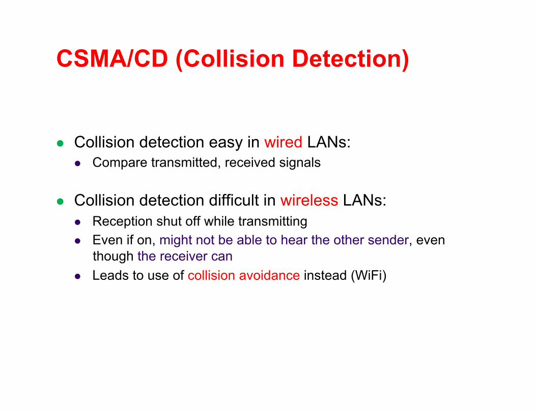
CSMA/CD (Collision Detection)
Collision detection easy in wired LANs: Compare transmitted, received signals
Collision detection difficult in wireless LANs: Reception shut off while transmitting Even if on, might not be able to hear the other sender, even
though the receiver can Leads to use of collision avoidance instead (WiFi)

Ethernet Multiple Access!

Ethernet
Bob Metcalfe, Xerox PARC, visits Hawaii and gets an idea
Shared wired medium coax cable

Ethernet: Typical Installation

CSMA/CD Protocol Carrier sense: wait for link to be idle
Collision detection: listen while transmitting No collision: transmission is complete Collision: abort transmission
Random access: binary exponential back-off After collision, wait a random time before trying again After mth collision, choose K randomly from {0, …, 2^m-1} … and wait for K*512 bit times before trying again Using min packet size as “slot” If transmission occurring when ready to send, wait until end of
transmission (CSMA)

BEB: Theory vs Reality In reality, BEB performs well (far from optimal, but no
one cares)
Is mostly irrelevant Almost all current ethernets are switched

Shuttling Data at Different Layers! Different devices switch different things
Physical layer: electrical signals (hubs) broadcast all bits
Link layer: frames (switches) forward based on MAC addresses
Network layer: packets (routers) forward based on IP headers
Router!
Switch!
Hub!
Frameheader!
Packetheader!
TCPheader!
User!data!
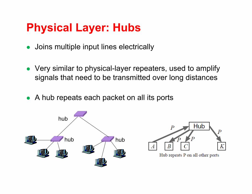
Physical Layer: Hubs Joins multiple input lines electrically
Very similar to physical-layer repeaters, used to amplify signals that need to be transmitted over long distances
A hub repeats each packet on all its ports
hub hub
hub

Limitations of Hubs One large collision domain
Every bit is sent everywhere So, aggregate throughput is limited E.g., three departments each get 10 Mbps independently … and then if connect via a hub must share 10 Mbps
Cannot support multiple LAN technologies Repeaters/hubs do not buffer or interpret frames So, can’t interconnect between different rates or formats E.g., no mixing 10 Mbps Ethernet & 100 Mbps Ethernet
Limitations on maximum nodes and distances E.g., still cannot go beyond 2500 meters on Ethernet
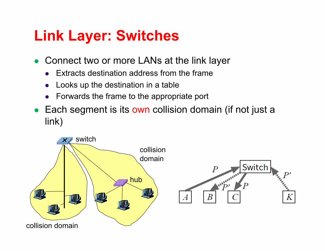
Link Layer: Switches Connect two or more LANs at the link layer
Extracts destination address from the frame Looks up the destination in a table Forwards the frame to the appropriate port
Each segment is its own collision domain (if not just a link)
hub
switch
collision domain
collision domain

Switched Ethernet If host has (dedicated) point-to-point link to switch:
Full duplex: each connection can send in both directions Completely avoids collisions No need for carrier sense, collision detection
For example: Host A can talk to C, while B talks to D
switch
A!
B!
C!
D!

Advantages over Hubs Only forwards frames as needed
Filters frames to avoid unnecessary load on segments Sends frames only to segments that need to see them
Extends the geographic span of the network Separate collision domains allow longer distances
Improves privacy by limiting scope of frames Hosts can “snoop” the traffic traversing their segment … but not all the rest of the traffic
Applies CSMA/CD in segment (not whole net) Smaller collision domain
Joins segments using different technologies
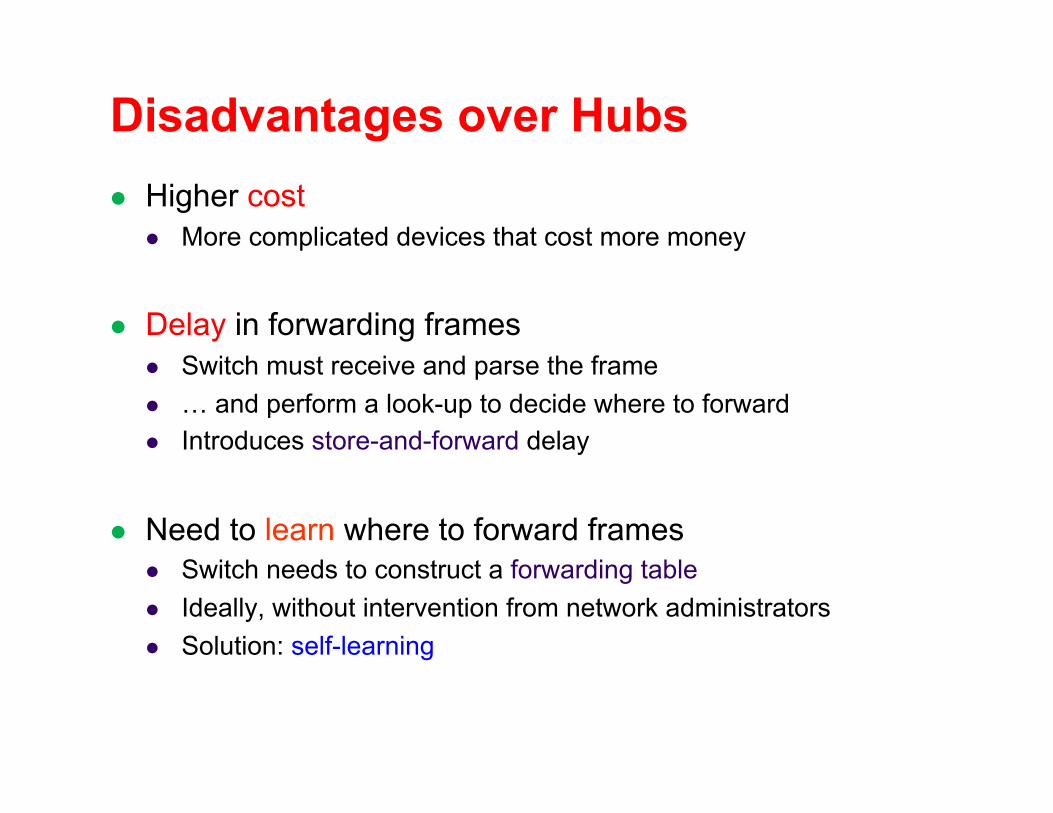
Disadvantages over Hubs Higher cost
More complicated devices that cost more money
Delay in forwarding frames Switch must receive and parse the frame … and perform a look-up to decide where to forward Introduces store-and-forward delay
Need to learn where to forward frames Switch needs to construct a forwarding table Ideally, without intervention from network administrators Solution: self-learning
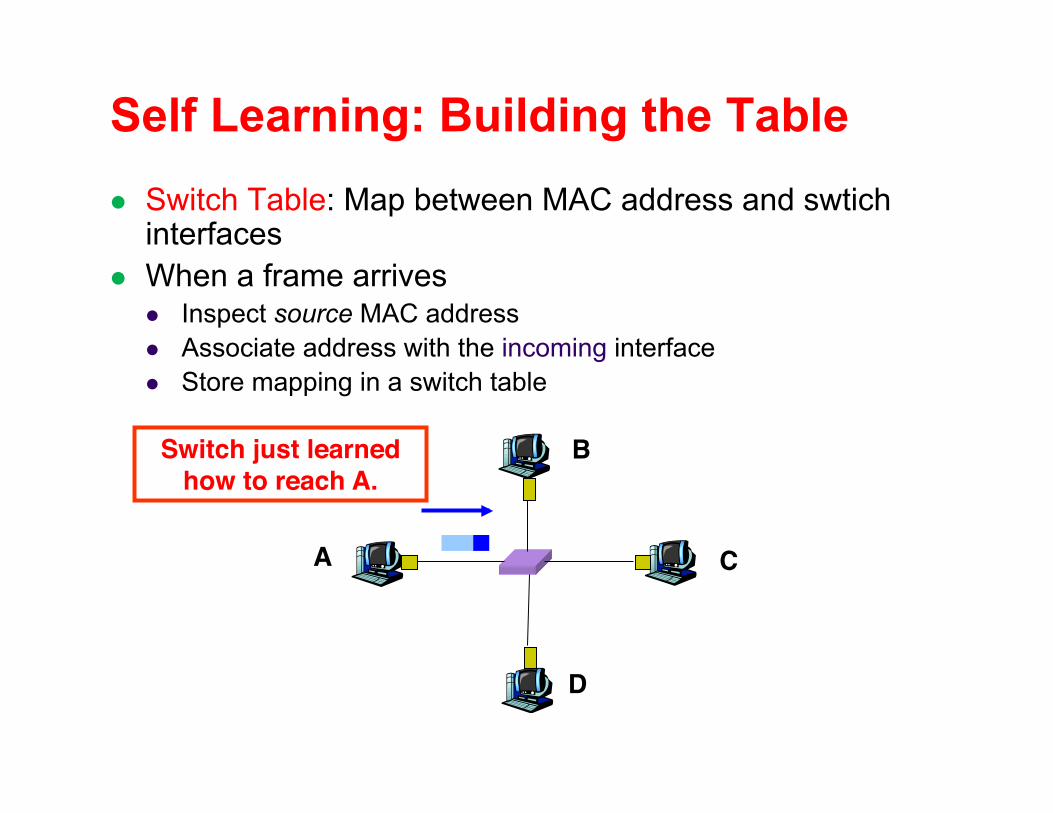
Self Learning: Building the Table Switch Table: Map between MAC address and swtich
interfaces When a frame arrives
Inspect source MAC address Associate address with the incoming interface Store mapping in a switch table
A!
B!
C!
D!
Switch just learned how to reach A.!

Self Learning: Handling Misses When frame arrives with unfamiliar destination
Forward the frame out all of the interfaces (“flooding”) … except for the one where the frame arrived
Hopefully, this case won’t happen very often When destination replies, switch learns that node, too
A!
B!
C!
D!
When in doubt, shout!!

Flooding Can Lead to Loops Switches sometimes need to broadcast frames
Upon receiving a frame with an unfamiliar destination Upon receiving a frame sent to the broadcast address Implemented by flooding
Flooding can lead to forwarding loops E.g., if the network contains a cycle of switches
Either accidentally, or by design for higher reliability

Solution: Spanning Trees Avoid using some of the links when flooding
Ensure the forwarding topology has no loops
Switches run a spanning tree protocol Form a sub-graph that covers all vertices but contains no cycles Links not in the spanning tree do not forward frames
Graph Has Cycles!
Graph Has No Cycles
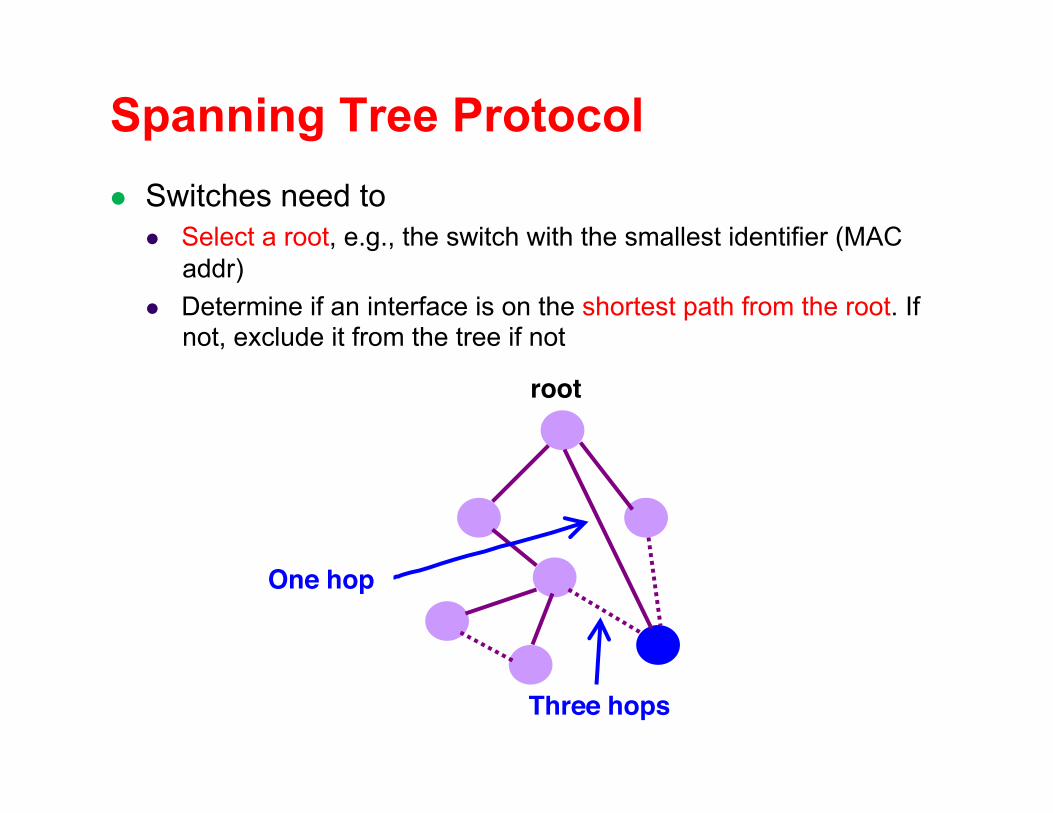
Spanning Tree Protocol Switches need to
Select a root, e.g., the switch with the smallest identifier (MAC addr)
Determine if an interface is on the shortest path from the root. If not, exclude it from the tree if not
root!
One hop!
Three hops!

Spanning Tree Protocol Switches exchange messages with information (myID, CurrentRootID, DistanceToCurrentRoot)
myID: ID (MAC address) of the switch CurrentRootID: ID of the proposed root DistanceToCurrentRoot: Distance from the switch to the
proposed root
A switch only relays messages whose CurrentRootID is the smallest the switch has seen so far Before forwarding the message, the DistanceToCurrentRoot is
increased by 1
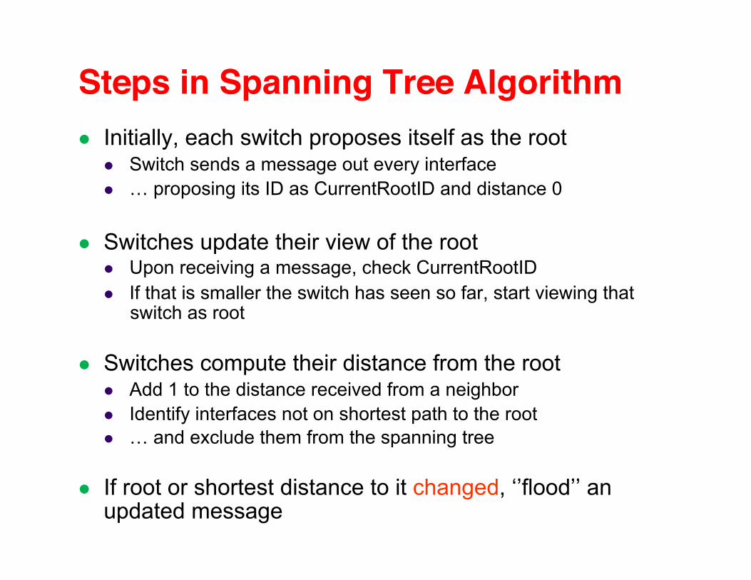
Steps in Spanning Tree Algorithm! Initially, each switch proposes itself as the root
Switch sends a message out every interface … proposing its ID as CurrentRootID and distance 0
Switches update their view of the root Upon receiving a message, check CurrentRootID If that is smaller the switch has seen so far, start viewing that
switch as root
Switches compute their distance from the root Add 1 to the distance received from a neighbor Identify interfaces not on shortest path to the root … and exclude them from the spanning tree
If root or shortest distance to it changed, ‘’flood’’ an updated message

Example From Switch #4’s Viewpoint!
Switch #4 thinks it is the root Sends (4, 4, 0) message to 2 and 7
Then, switch #4 hears from #2 Receives (2, 2, 0) message from 2 … and thinks that #2 is the root And realizes it is just one hop away
Then, switch #4 hears from #7 Receives (7, 2, 1) from 7 And realizes this is a longer path So, prefers its own one-hop path And removes 4-7 link from the tree
1!
2!
3!
4!
5!
6!7!

Example From Switch #4’s Viewpoint!
Switch #2 hears about switch #1 Switch 2 hears (3, 1, 1) from 3 Switch 2 starts treating 1 as root And sends (2, 1, 2) to neighbors
Switch #4 hears from switch #2 Switch 4 starts treating 1 as root And sends (4, 1, 3) to neighbors
Switch #4 hears from switch #7 Switch 4 receives (7, 1, 3) from 7 And realizes this is a longer path So, prefers its own three-hop path And removes 4-7 Iink from the tree
1!
2!
3!
4!
5!
6!7!

Summary Ethernet as an exemplar of link-layer technology Simplest form, single segment:
Carrier sense, collision detection, and random access
Extended to span multiple segments: Hubs: physical-layer interconnects Switches: link-layer interconnects
Key ideas in switches Self learning of the switch table Spanning trees