EC2405 - Microwave Experiments.pdf
34
Optical and Microwave Lab Manual Dr.NGP INSTITUTE OF TECHNOLOGY DEPT: ECE YEAR & SEM : IV & 07 Dr. N.G.P. INSTITUTE OF TECHNOLOGY COIMBATORE – 48. DEPARTMENT OF ELECTRONICS AND COMMUNICATION ENGINEERING OPTICAL AND MICROWAVE LABORATORY MANUAL Class : IV B.E – ECE - A&B Regulation : 2008 Semester : 07 Lab Code : 080290061 Prepared by Verified by Mr.S.SHANMUG RAJU AP/ECE Dr.N.G.P.IT Ms.V.SANGEETHAPOORANI AP/ECE Dr.N.G.P.IT Dr.S.SURESH KUMAR DIRECTOR-RESEARCH,HoD/ECE Dr.N.G.P.IT www.Vidyarthiplus.com www.Vidyarthiplus.com
-
Upload
9985237595 -
Category
Documents
-
view
73 -
download
5
description
EC2405 - Microwave Experiments.pdf
Transcript of EC2405 - Microwave Experiments.pdf
Optical and Microwave Lab Manual
Dr.NGP INSTITUTE OF TECHNOLOGY DEPT: ECE YEAR & SEM : IV & 07
Dr. N.G.P. INSTITUTE OF TECHNOLOGY COIMBATORE – 48.
DEPARTMENT OF
ELECTRONICS AND COMMUNICATION ENGINEERING
OPTICAL AND MICROWAVE LABORATORY MANUAL Class : IV B.E – ECE - A&B Regulation : 2008 Semester : 07
Lab Code : 080290061
Prepared by Verified by Mr.S.SHANMUG RAJU
AP/ECE Dr.N.G.P.IT
Ms.V.SANGEETHAPOORANI
AP/ECE Dr.N.G.P.IT
Dr.S.SURESH KUMAR DIRECTOR-RESEARCH,HoD/ECE
Dr.N.G.P.IT
www.Vidyarthiplus.com
www.Vidyarthiplus.com

Optical and Microwave Lab Manual
Dr.NGP INSTITUTE OF TECHNOLOGY DEPT: ECE YEAR & SEM : IV & 07
CYCLE I
www.Vidyarthiplus.com
www.Vidyarthiplus.com
Optical and Microwave Lab Manual
Dr.NGP INSTITUTE OF TECHNOLOGY DEPT: ECE YEAR & SEM : IV & 07
www.Vidyarthiplus.com
www.Vidyarthiplus.com
Optical and Microwave Lab Manual
Dr.NGP INSTITUTE OF TECHNOLOGY DEPT: ECE YEAR & SEM : IV & 07
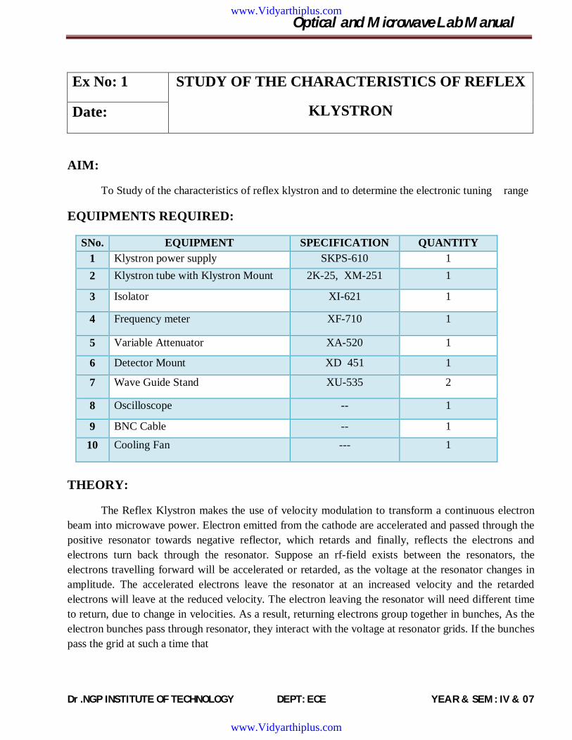
Ex No: 1 STUDY OF THE CHARACTERISTICS OF REFLEX
KLYSTRON Date:
AIM:
To Study of the characteristics of reflex klystron and to determine the electronic tuning range
EQUIPMENTS REQUIRED:
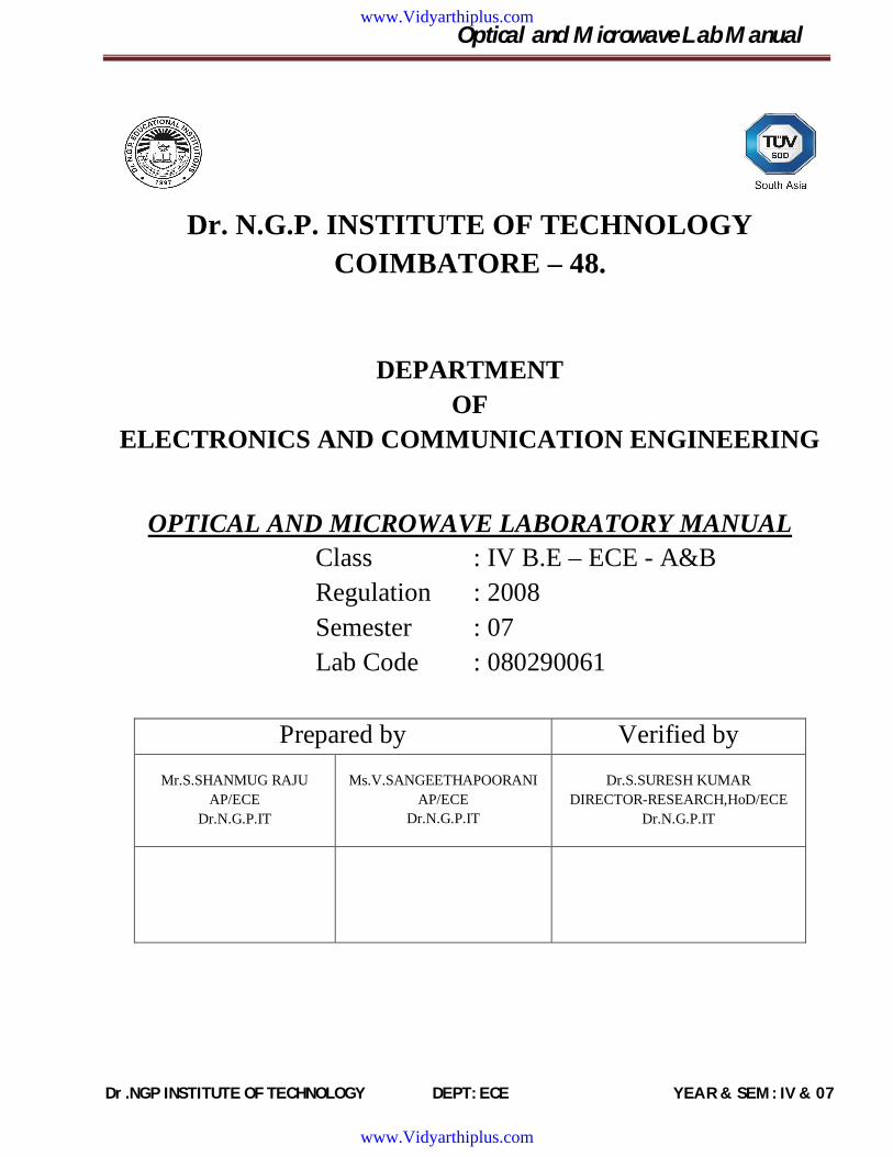
SNo. EQUIPMENT SPECIFICATION QUANTITY 1 Klystron power supply SKPS-610 1 2 Klystron tube with Klystron Mount 2K-25, XM-251 1
3 Isolator XI-621 1
4 Frequency meter XF-710 1
5 Variable Attenuator XA-520 1
6 Detector Mount XD 451 1
7 Wave Guide Stand XU-535 2
8 Oscilloscope -- 1
9 BNC Cable -- 1
10 Cooling Fan --- 1
THEORY:
The Reflex Klystron makes the use of velocity modulation to transform a continuous electron beam into microwave power. Electron emitted from the cathode are accelerated and passed through the positive resonator towards negative reflector, which retards and finally, reflects the electrons and electrons turn back through the resonator. Suppose an rf-field exists between the resonators, the electrons travelling forward will be accelerated or retarded, as the voltage at the resonator changes in amplitude. The accelerated electrons leave the resonator at an increased velocity and the retarded electrons will leave at the reduced velocity. The electron leaving the resonator will need different time to return, due to change in velocities. As a result, returning electrons group together in bunches, As the electron bunches pass through resonator, they interact with the voltage at resonator grids. If the bunches pass the grid at such a time that
www.Vidyarthiplus.com
www.Vidyarthiplus.com
Optical and Microwave Lab Manual
Dr.NGP INSTITUTE OF TECHNOLOGY DEPT: ECE YEAR & SEM : IV & 07
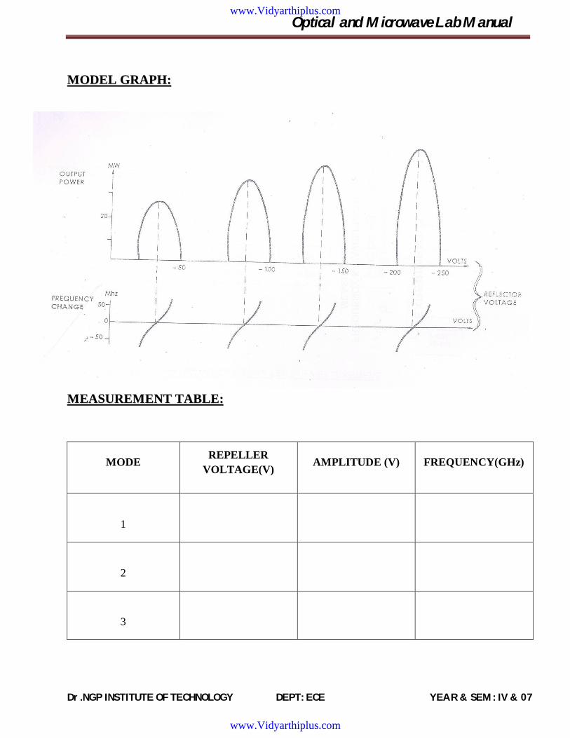
MMOODDEELL GGRRAAPPHH::
MMEEAASSUURREEMMEENNTT TTAABBLLEE::
MODE REPELLER VOLTAGE(V) AMPLITUDE (V) FREQUENCY(GHz)
1
2
3
www.Vidyarthiplus.com
www.Vidyarthiplus.com

Optical and Microwave Lab Manual
Dr.NGP INSTITUTE OF TECHNOLOGY DEPT: ECE YEAR & SEM : IV & 07
electrons are slowed down by the voltage then energy will be delivered to the resonator and klystron will oscillate. Fig shows the relationship between output power, frequency and reflector voltages.
The frequency is primarily determined by the dimensions of resonant cavity. Hence, by changing the volume of resonator, mechanical tuning of Klystron is possible. Also a small frequency change can be obtained by adjusting the reflector voltage. This is called Electronic Tuning.
PROCEDURE:
1. Set up the components and equipments as shown in fig.
2. Keep the position of variable attenuator at minimum attenuation position.
3. Set mode selector switch to FM-MOD position, FM amplitude and Fm frequency knob at mid position, keep beam voltage knob fully anticlockwise and reflector voltage knob to fully clockwise and Beam switch to ‘OFF’ position.
4. Keep the time/division scale of oscilloscope around 100Hz frequency measurement and volt/div to lower scale.
5. Switch ON the Klystron Power Supply and Oscilloscope.
6. Switch ON Beam voltage switch and set beam voltage to 300V by beam voltage control knob.
7. Keep amplitude knob of FM Modulator to maximum position and rotate the reflector voltage anticlockwise to get modes as shown in fig.2 on the oscilloscope. The horizontal axis represents axis represents reflector voltage axis and vertical represents output power.
8. By changing the reflector voltage and amplitude of FM modulation, any mode of Klystron tube can be seen on Oscilloscope.
RESULT:
www.Vidyarthiplus.com
www.Vidyarthiplus.com

Optical and Microwave Lab Manual
Dr.NGP INSTITUTE OF TECHNOLOGY DEPT: ECE YEAR & SEM : IV & 07
SET
UP
FOR
ST
UD
Y O
F G
UN
N D
IOD
E
www.Vidyarthiplus.com
www.Vidyarthiplus.com

Optical and Microwave Lab Manual
Dr.NGP INSTITUTE OF TECHNOLOGY DEPT: ECE YEAR & SEM : IV & 07
Ex No: 2 CHARACTERISTICS OF GUNN DIODE Date:
AIM:
To Study of the characteristics of Gunn diode and to determine the threshold voltage that corresponds to maximum current.
EQUIPMENTS REQUIRED:
SNo. EQUIPMENT SPECIFICATION QUANTITY
1. Gunn power supply GS-610 1
2. Gunn oscillator XM-55 1
3. Pin modulator XM-55 1
4. Isolator XI-621 1
5. Frequency meter XF-710 1
6. Variable Attenuator XA-520 1
7. Detector Mount XD-451 1
8. VSWR Meter SW-115 1
9. BNC Cable -- 1
10. Cooling Fan --- 1
11. Wave Guide Stand --- 2
PROCEDURE: 1. Set the components as shown in the fig. 2. Keep the control knobs of Gunn power supply as below
www.Vidyarthiplus.com
www.Vidyarthiplus.com
Optical and Microwave Lab Manual
Dr.NGP INSTITUTE OF TECHNOLOGY DEPT: ECE YEAR & SEM : IV & 07
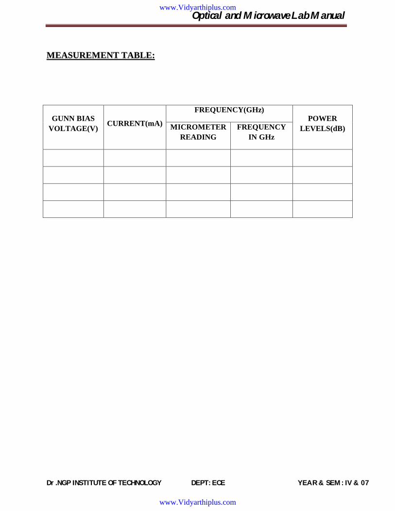
MMEEAASSUURREEMMEENNTT TTAABBLLEE::
GUNN BIAS VOLTAGE(V) CURRENT(mA)
FREQUENCY(GHz) POWER
LEVELS(dB) MICROMETER READING
FREQUENCY IN GHz
www.Vidyarthiplus.com
www.Vidyarthiplus.com

Optical and Microwave Lab Manual
Dr.NGP INSTITUTE OF TECHNOLOGY DEPT: ECE YEAR & SEM : IV & 07
Meter Switch - OFF
Gunn bias knob - Fully anticlockwise
PIN bias knob - Fully anticlockwise
PIN Mode frequency - Any position
3. Set the micrometer of Gunn oscillator for required frequency of operation
4. Switch ON the Gunn power supply
5. Measure the Gunn diode current corresponding to various Gunn bias voltages through the digital panel meter and meter switch. Do not exceed the bias voltage above 10 volts
6. Tune the output in the VSWR meter through frequency control knob of modulation
7. If required then change the range db switch of VSWR meter to higher db position to get deflection on VSWR meter. Any level can be set through variable attenuator and gain control knob of VSWR meter.
8. Measure the frequency meter and detune it.
9. Plot the voltage and current readings on the graph as shown in fig.
10 Measure the threshold voltage which corresponds to maximum current.
Note: Do not keep Gun bias knob position at threshold position for more than 10-15 seconds reading should be obtained as fast as possible. Otherwise due to excessive heating, gun diode may burn.
RESULT:
www.Vidyarthiplus.com
www.Vidyarthiplus.com
Optical and Microwave Lab Manual
Dr.NGP INSTITUTE OF TECHNOLOGY DEPT: ECE YEAR & SEM : IV & 07
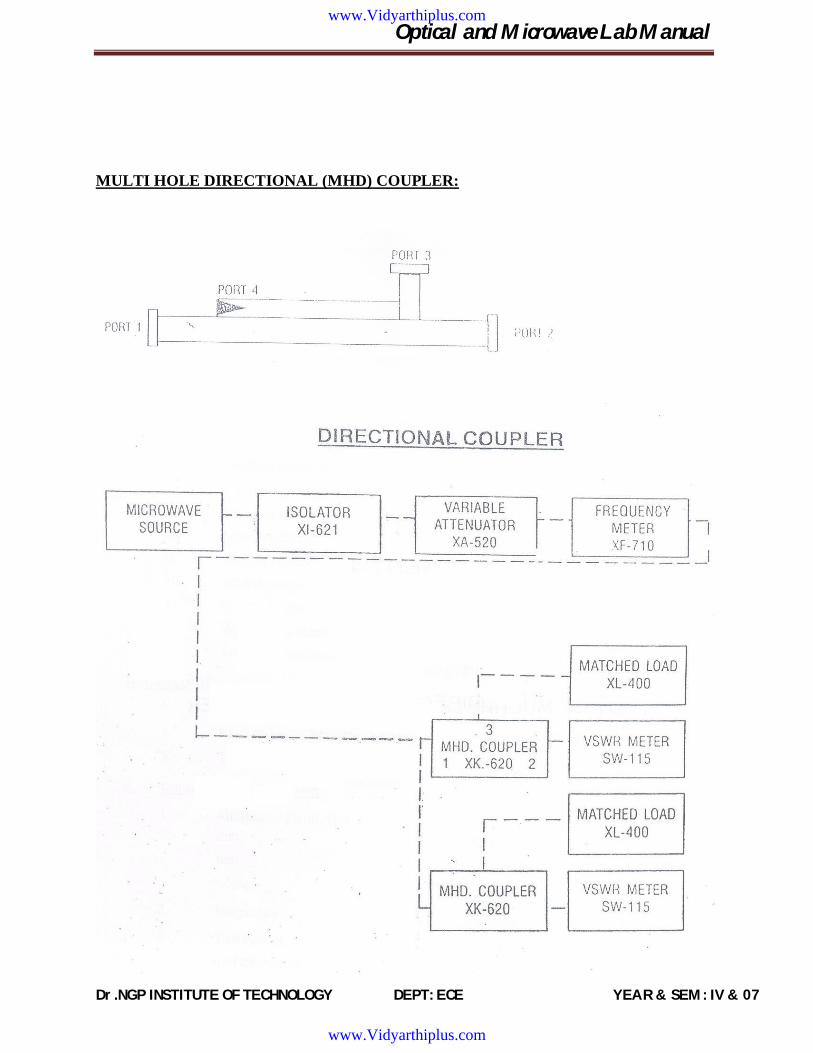
MULTI HOLE DIRECTIONAL (MHD) COUPLER:
www.Vidyarthiplus.com
www.Vidyarthiplus.com

Optical and Microwave Lab Manual
Dr.NGP INSTITUTE OF TECHNOLOGY DEPT: ECE YEAR & SEM : IV & 07
Ex No: 3 STUDY OF POWER DISTRIBUTION IN DIRECTIONAL COUPLER Date:
AIM:
To study the function of multihole directional coupler by measuring the following parameters
i. Mainline and auxiliary-line VSWR
ii. The coupling factor and directivity of the coupler
EQUIPMENTS REQUIRED:
SNo. EQUIPMENT SPECIFICATION QUANTITY 1. Klystron power supply SKPS-610 1
2. Klystron tube with Klystron Mount 2K-25, XM-251 1
3. Isolator XI-621 1
4. Frequency meter XF-710 1
5. Variable Attenuator XA-520 1
6. Detector Mount XD 451 1
7. Matched Termination XL 400 2
8. MHD Coupler XK 620 1
9. Waveguide Stand -- 2
10. BNC Cable -- 1
11. VSWR meter -- 1
12. Cooling Fan -- 1
www.Vidyarthiplus.com
www.Vidyarthiplus.com
Optical and Microwave Lab Manual
Dr.NGP INSTITUTE OF TECHNOLOGY DEPT: ECE YEAR & SEM : IV & 07
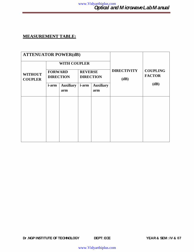
MMEEAASSUURREEMMEENNTT TTAABBLLEE::
ATTENUATOR POWER(dB)
DIRECTIVITY
(dB)
COUPLING FACTOR
(dB)
WITHOUT COUPLER
WITH COUPLER
FORWARD DIRECTION
REVERSE DIRECTION
i-arm Auxiliary arm
i-arm Auxiliary arm
www.Vidyarthiplus.com
www.Vidyarthiplus.com

Optical and Microwave Lab Manual
Dr.NGP INSTITUTE OF TECHNOLOGY DEPT: ECE YEAR & SEM : IV & 07
THEORY:
A directional coupler is a device with which it is possible to measure the incident and reflected wave separately. It consist of wo transmission line the main arm and auxiliary arm, electromagnetically coupled to each other. The power entering in the main arm gets divided between port2 and 3 and almost no power comes out in port 4. Power entering at port2 is divided between port1 and 4.
The coupling factor is defined as
Coupling (db) = 10 log10(P1/P2)
Where port2 is terminated.
Isolation (db) = 10 log10(P2/P3)
Where P1 is matched.
With built-in termination and power entering at Port1, the directivity of the coupler is a measure of separation between incident wave and the reflected wave.Directivity is measured indirectly,
Directivity D (db)= 10 log10(P2/P1)
Main line VSWR is SWR measured, looking into the main line input terminal when the matched loads are placed at all other ports.
Auxiliary line VSWR is SWR measured in the auxiliary line looking into the output terminal when the matched loads are placed on other terminals
Main line insertion loss is the attenuation introduced in the transmission line by insertion of coupler. It is defined as
Insertion loss (dB) = 10 log10 (P1/P2)
PROCEDURE:
A. Main Line SWR Measurement
1. Set up the equipments as shown in fig
2. Energies the microwave sources for particular frequency of operation as described in the procedures given in the operation of Klystron tube/Gunn Oscillator
3. Follow the procedure as described for VSWR measurement(low and medium SWR measurement)
www.Vidyarthiplus.com
www.Vidyarthiplus.com
Optical and Microwave Lab Manual
Dr.NGP INSTITUTE OF TECHNOLOGY DEPT: ECE YEAR & SEM : IV & 07
4. Repeat the same for other frequencies.
B. Auxiliary Line SWR Measurement
1. Set up the components and equipments as shown in fig
2. Energies the microwave sources for particular frequency of operation as described in the operation of Klystron tube/Gunn Oscillator
3. Measure SWR as described in the experiment of SWR measurement (low and medium SWR measurement)
4. Repeat the same for other frequencies.
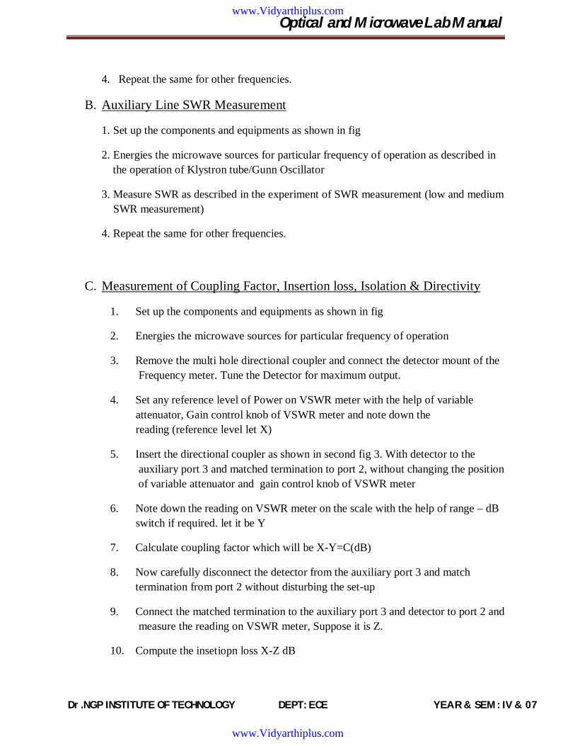
C. Measurement of Coupling Factor, Insertion loss, Isolation & Directivity
1. Set up the components and equipments as shown in fig
2. Energies the microwave sources for particular frequency of operation
3. Remove the multi hole directional coupler and connect the detector mount of the Frequency meter. Tune the Detector for maximum output.
4. Set any reference level of Power on VSWR meter with the help of variable attenuator, Gain control knob of VSWR meter and note down the reading (reference level let X)
5. Insert the directional coupler as shown in second fig 3. With detector to the auxiliary port 3 and matched termination to port 2, without changing the position of variable attenuator and gain control knob of VSWR meter
6. Note down the reading on VSWR meter on the scale with the help of range – dB switch if required. let it be Y
7. Calculate coupling factor which will be X-Y=C(dB)
8. Now carefully disconnect the detector from the auxiliary port 3 and match termination from port 2 without disturbing the set-up
9. Connect the matched termination to the auxiliary port 3 and detector to port 2 and measure the reading on VSWR meter, Suppose it is Z.
10. Compute the insetiopn loss X-Z dB
www.Vidyarthiplus.com
www.Vidyarthiplus.com

Optical and Microwave Lab Manual
Dr.NGP INSTITUTE OF TECHNOLOGY DEPT: ECE YEAR & SEM : IV & 07
11. Repeat the steps from 1 to 4.
12. Connect the directional coupler in the reverse direction i.e., port 2 to frequency meter side. Matched termination to port 1 and detector mount to prt 3 without disturbing the position of the variable attenuator and gain control knob of VSWR meter.
13. Measure and note down the reading on VSWR meter. Let it be Yd. X- Yd gives Isolation (dB)
14. Compute the Directivity as Y-Yd= I-C
15. Repeat the same for other frequencies.
RESULT:
www.Vidyarthiplus.com
www.Vidyarthiplus.com
Optical and Microwave Lab Manual
Dr.NGP INSTITUTE OF TECHNOLOGY DEPT: ECE YEAR & SEM : IV & 07
www.Vidyarthiplus.com
www.Vidyarthiplus.com
Optical and Microwave Lab Manual
Dr.NGP INSTITUTE OF TECHNOLOGY DEPT: ECE YEAR & SEM : IV & 07
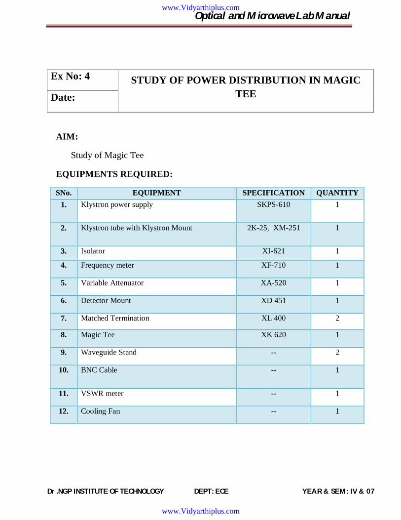
Ex No: 4 STUDY OF POWER DISTRIBUTION IN MAGIC TEE Date:
AIM:
Study of Magic Tee
EQUIPMENTS REQUIRED:
SNo. EQUIPMENT SPECIFICATION QUANTITY 1. Klystron power supply SKPS-610 1
2. Klystron tube with Klystron Mount 2K-25, XM-251 1
3. Isolator XI-621 1
4. Frequency meter XF-710 1
5. Variable Attenuator XA-520 1
6. Detector Mount XD 451 1
7. Matched Termination XL 400 2
8. Magic Tee XK 620 1
9. Waveguide Stand -- 2
10. BNC Cable -- 1
11. VSWR meter -- 1
12. Cooling Fan -- 1
www.Vidyarthiplus.com
www.Vidyarthiplus.com
Optical and Microwave Lab Manual
Dr.NGP INSTITUTE OF TECHNOLOGY DEPT: ECE YEAR & SEM : IV & 07
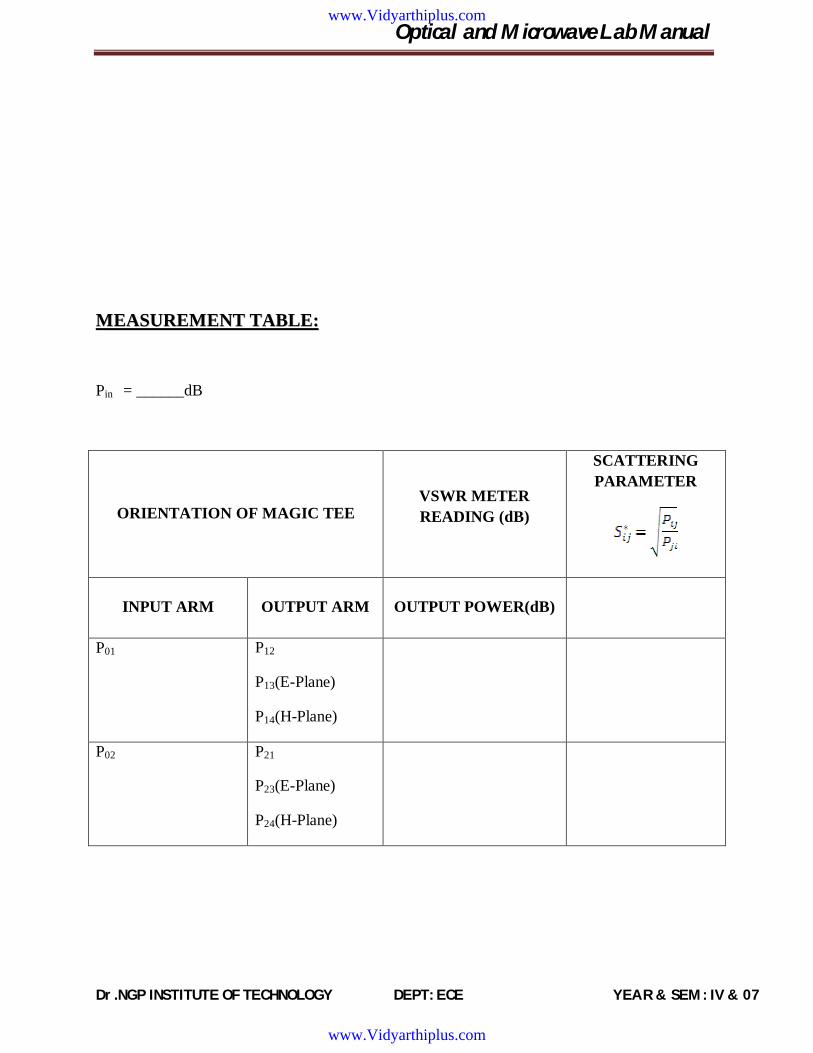
MMEEAASSUURREEMMEENNTT TTAABBLLEE::
Pin = ______dB
ORIENTATION OF MAGIC TEE VSWR METER READING (dB)
SCATTERING PARAMETER
INPUT ARM OUTPUT ARM OUTPUT POWER(dB)
P01 P12
P13(E-Plane)
P14(H-Plane)
P02 P21
P23(E-Plane)
P24(H-Plane)
www.Vidyarthiplus.com
www.Vidyarthiplus.com
Optical and Microwave Lab Manual
Dr.NGP INSTITUTE OF TECHNOLOGY DEPT: ECE YEAR & SEM : IV & 07
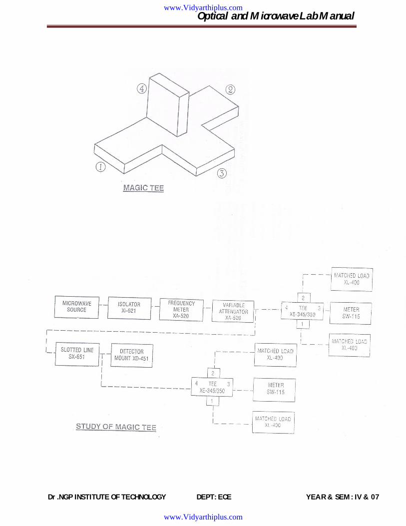
THEORY:
The device magic Tee is a combination of E and H palne Tee. Arm 3 is the H-arm and arm 4 is the E-arm. If the power is fed into arm 3 (H-arm) the electric field divides equally between arm 1 and 2 wih the same phase, and no electric field exists in arm 4. If power is fed in arm 4(E-arm). It divides equally into arm and 2 but out of phase with no powerto arm 3. Further, if power is fed in arm 1 and 2 simultaneously it is added in arm 3 (H-arm) and it is subtracted in E-arm i.e arm 4
The basic parameters to be measured for magic Tee are defined below
A. Input VSWR
Value of SWR corresponding to each port, as a load to the line while other ports are terminated in matched load.
B. Isolation
The Isolation between E and H arms is defined as the ration of the power supplied by the generator connected to the E-arm (port 4) to the power detected at H-arm (port3) when side arms 1 and 2 terminated in matched load.
Hence Isolation (dB) = 10 log10(P4/P3)
Similarly, isolation between other ports may also be defined.
C. COUPLING FACTOR
It is defined as Cij= 10-α/20
Where α is the attenuation / isolation in dB when I is input arm and j is output arm
Thus α=10 log10(P4/P3)
Where P3 is the power delievered to arm I and P4 is power detected at j arm
PROCEDURE:
A.VSWR MEASUREMENTS AT PORTS
1. Set up the components and equipments as shown in fig. Keeping E arm towards slotted line and match the termination to other ports.
2. Energise the microwave sources for particular frequency of operation
www.Vidyarthiplus.com
www.Vidyarthiplus.com

Optical and Microwave Lab Manual
Dr.NGP INSTITUTE OF TECHNOLOGY DEPT: ECE YEAR & SEM : IV & 07
3. Measure VSWR of E arms as described in measurement of SWR for low and medium value
5. Connect another arm to slotted line and terminate the other port with matched termination. Measure the VSWR as above. Similarly, VSWR of any port can be measured.
B. Measurement of Isolation and Coupling factor
1. Remove the tunable probe and magic Tee from the slotted line and connect the detector mount to slotted line.
2. Energise the microwave sources for particular frequency of operation and tune the detector mount for maximum output
3. With the help of variable attenuator and gain control knob of VSWR meter, set any power level in VSWR meter and note down. Let it be P3.
4. Without disturbing the position of variable attenuator and gain control knob, carefully place the Magic Tee after slotted line. Keeping H arm connected to slotted line, detector to E arm and matched termination to arm 1 and 2. Note down the reading of VSWR meter. Let it be P4.
5. Determine the Isolation between port 3 and 4 as P3-P4 in dB. 6. Determine th e coupling coefficient from equation given in the theory part.
7. The same experiment may be repeated for other ports also.
8. Repeat the above experiment fo r other frequencies.
RESULT:
www.Vidyarthiplus.com
www.Vidyarthiplus.com
Optical and Microwave Lab Manual
Dr.NGP INSTITUTE OF TECHNOLOGY DEPT: ECE YEAR & SEM : IV & 07
www.Vidyarthiplus.com
www.Vidyarthiplus.com

Optical and Microwave Lab Manual
Dr.NGP INSTITUTE OF TECHNOLOGY DEPT: ECE YEAR & SEM : IV & 07
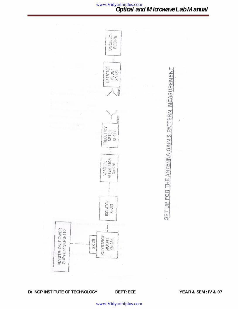
Ex No: 5 MEASUREMENT OF THE GAIN AND POLAR
PATTERN OF HORN ANTENNA Date:
AIM:
To measure the polar pattern and the gain of a waveguide horn antenna.
EQUIPMENTS REQUIRED:
SNo. EQUIPMENT SPECIFICATION QUANTITY 1 Klystron power supply SKPS-610 1 2 Klystron tube with Klystron Mount 2K-25, XM-251 1
3 Isolator XI-621 1
4 Frequency meter XF-710 1
5 Variable Attenuator XA-520 1
6 Detector Mount XD 451 1
7 Wave Guide Stand XU-535 2
8 Oscilloscope -- 1
9 BNC Cable -- 1
10 Cooling Fan --- 1
THEORY:
If a transmission line, propagating energy is left open at one end , there will be radiation from this end. In case of a rectangular waveguide this antenna presents a mismatch of about 2 and it radiates in many directions. The match will improve if the open waveguide is a horn shape.
The radiation pattern of an antenna is a plot of field strength of the power intensity as a function of the aspect angle at a constant distance from the radiating antenna. An antenna pattern is ofcourse three dimensional but for practical reasons it is normally presented as a two
www.Vidyarthiplus.com
www.Vidyarthiplus.com

Optical and Microwave Lab Manual
Dr.NGP INSTITUTE OF TECHNOLOGY DEPT: ECE YEAR & SEM : IV & 07
MMEEAASSUURREEMMEENNTT TTAABBLLEE::
Frequency =
S =
ANGLE (degrees) VT (v) VR (v) GAIN
www.Vidyarthiplus.com
www.Vidyarthiplus.com
Optical and Microwave Lab Manual
Dr.NGP INSTITUTE OF TECHNOLOGY DEPT: ECE YEAR & SEM : IV & 07
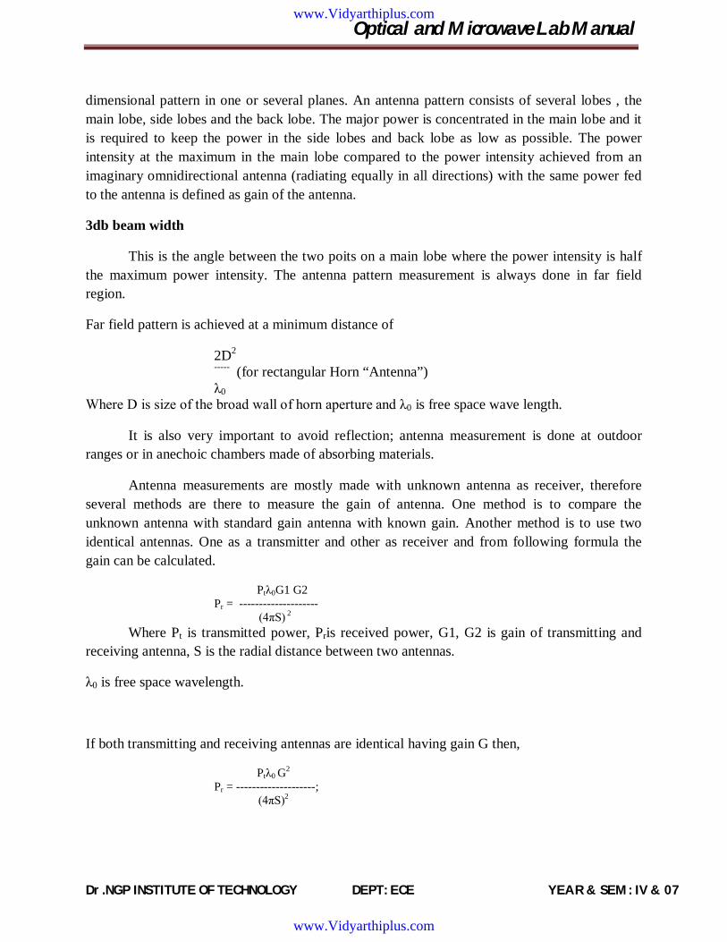
dimensional pattern in one or several planes. An antenna pattern consists of several lobes , the main lobe, side lobes and the back lobe. The major power is concentrated in the main lobe and it is required to keep the power in the side lobes and back lobe as low as possible. The power intensity at the maximum in the main lobe compared to the power intensity achieved from an imaginary omnidirectional antenna (radiating equally in all directions) with the same power fed to the antenna is defined as gain of the antenna.
3db beam width
This is the angle between the two poits on a main lobe where the power intensity is half the maximum power intensity. The antenna pattern measurement is always done in far field region.
Far field pattern is achieved at a minimum distance of
2D2
----- (for rectangular Horn “Antenna”) λ0
Where D is size of the broad wall of horn aperture and λ0 is free space wave length.
It is also very important to avoid reflection; antenna measurement is done at outdoor ranges or in anechoic chambers made of absorbing materials.
Antenna measurements are mostly made with unknown antenna as receiver, therefore several methods are there to measure the gain of antenna. One method is to compare the unknown antenna with standard gain antenna with known gain. Another method is to use two identical antennas. One as a transmitter and other as receiver and from following formula the gain can be calculated.
Ptλ0G1 G2 Pr = -------------------- (4πS) 2
Where Pt is transmitted power, Pris received power, G1, G2 is gain of transmitting and receiving antenna, S is the radial distance between two antennas.
λ0 is free space wavelength.
If both transmitting and receiving antennas are identical having gain G then,
Ptλ0 G2 Pr = --------------------;
(4πS)2
www.Vidyarthiplus.com
www.Vidyarthiplus.com
Optical and Microwave Lab Manual
Dr.NGP INSTITUTE OF TECHNOLOGY DEPT: ECE YEAR & SEM : IV & 07
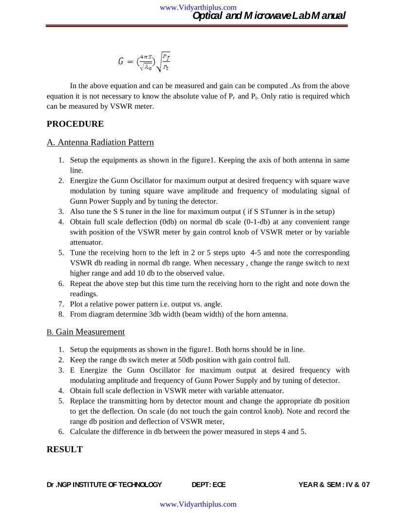
In the above equation and can be measured and gain can be computed .As from the above equation it is not necessary to know the absolute value of Pr and Pt. Only ratio is required which can be measured by VSWR meter.
PROCEDURE
A. Antenna Radiation Pattern
1. Setup the equipments as shown in the figure1. Keeping the axis of both antenna in same line.
2. Energize the Gunn Oscillator for maximum output at desired frequency with square wave modulation by tuning square wave amplitude and frequency of modulating signal of Gunn Power Supply and by tuning the detector.
3. Also tune the S S tuner in the line for maximum output ( if S STunner is in the setup) 4. Obtain full scale deflection (0db) on normal db scale (0-1-db) at any convenient range
swith position of the VSWR meter by gain control knob of VSWR meter or by variable attenuator.
5. Tune the receiving horn to the left in 2 or 5 steps upto 4-5 and note the corresponding VSWR db reading in normal db range. When necessary , change the range switch to next higher range and add 10 db to the observed value.
6. Repeat the above step but this time turn the receiving horn to the right and note down the readings.
7. Plot a relative power pattern i.e. output vs. angle. 8. From diagram determine 3db width (beam width) of the horn antenna.
B. Gain Measurement
1. Setup the equipments as shown in the figure1. Both horns should be in line. 2. Keep the range db switch meter at 50db position with gain control full. 3. E Energize the Gunn Oscillator for maximum output at desired frequency with
modulating amplitude and frequency of Gunn Power Supply and by tuning of detector. 4. Obtain full scale deflection in VSWR meter with variable attenuator. 5. Replace the transmitting horn by detector mount and change the appropriate db position
to get the deflection. On scale (do not touch the gain control knob). Note and record the range db position and deflection of VSWR meter,
6. Calculate the difference in db between the power measured in steps 4 and 5.
RESULT
www.Vidyarthiplus.com
www.Vidyarthiplus.com
Optical and Microwave Lab Manual
Dr.NGP INSTITUTE OF TECHNOLOGY DEPT: ECE YEAR & SEM : IV & 07
www.Vidyarthiplus.com
www.Vidyarthiplus.com

Optical and Microwave Lab Manual
Dr.NGP INSTITUTE OF TECHNOLOGY DEPT: ECE YEAR & SEM : IV & 07
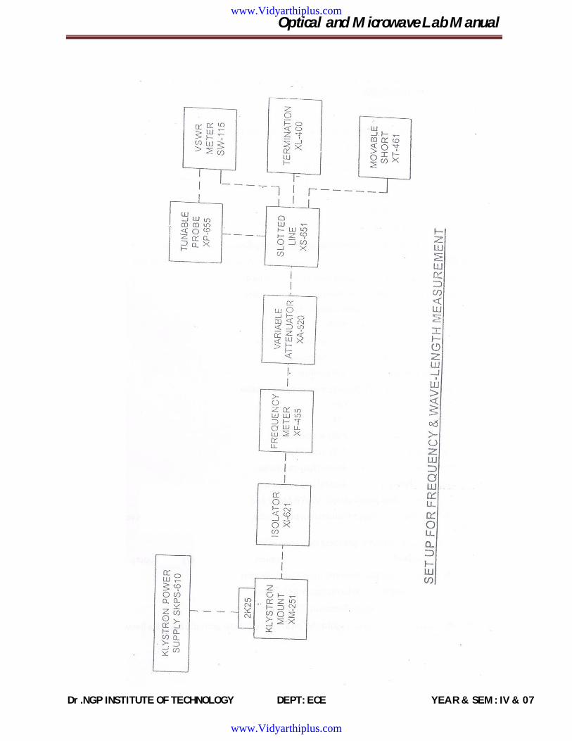
Ex No: 6 DETERMINTAION OF GUIDE WAVELENGTH, FREQUENCY
MEASUREMENT Date:
AIM:
To determine the frequency and wavelength in a rectangular waveguide working in TE mode.
EQUIPMENT:
SNo. EQUIPMENT SPECIFICATION QUANTITY 1 Klystron power supply SKPS-610 1 2 Klystron tube with Klystron Mount 2K-25, XM-251 1
3 Isolator XI-621 1
4 Frequency meter XF-710 1
5 Variable Attenuator XA-520 1
6 Slotted section XS 651 1
7 Tunable Probe XP-655 1
8 VSWR Meter SW-115 1
9 Movable Short XT-4813 1
10 Wave Guide Stand XU-535 2
11 Matched Termination XL-400 1
12 Oscilloscope -- 1
13 BNC Cable -- 1
14 Cooling Fan --- 1
THEORY
For dominant TE mode rectangular waveguide Io,Igand Ic are related as below
www.Vidyarthiplus.com
www.Vidyarthiplus.com
Optical and Microwave Lab Manual
Dr.NGP INSTITUTE OF TECHNOLOGY DEPT: ECE YEAR & SEM : IV & 07
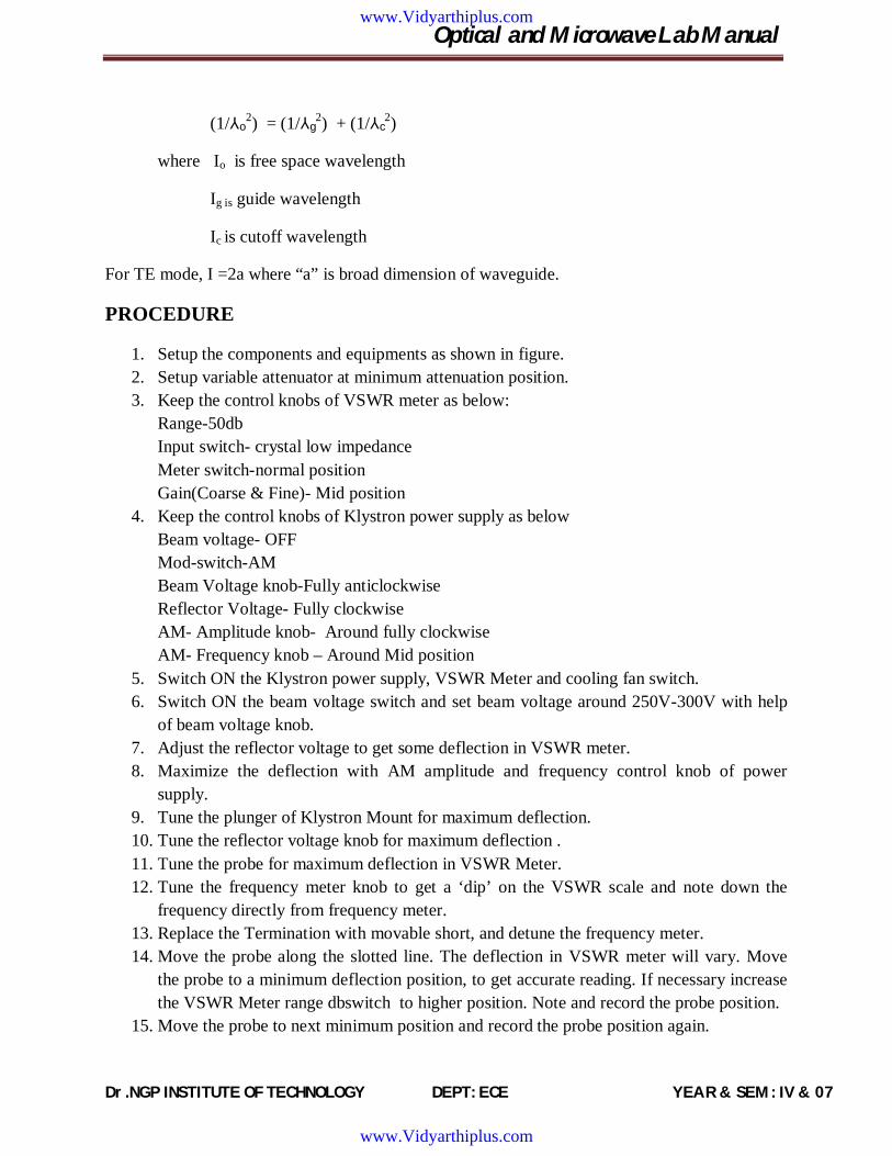
(1/⅄o2) = (1/⅄g
2) + (1/⅄c2)
where Io is free space wavelength
Ig is guide wavelength
Ic is cutoff wavelength
For TE mode, I =2a where “a” is broad dimension of waveguide.
PROCEDURE
1. Setup the components and equipments as shown in figure. 2. Setup variable attenuator at minimum attenuation position. 3. Keep the control knobs of VSWR meter as below:
Range-50db Input switch- crystal low impedance Meter switch-normal position Gain(Coarse & Fine)- Mid position
4. Keep the control knobs of Klystron power supply as below Beam voltage- OFF Mod-switch-AM Beam Voltage knob-Fully anticlockwise Reflector Voltage- Fully clockwise AM- Amplitude knob- Around fully clockwise AM- Frequency knob – Around Mid position
5. Switch ON the Klystron power supply, VSWR Meter and cooling fan switch. 6. Switch ON the beam voltage switch and set beam voltage around 250V-300V with help
of beam voltage knob. 7. Adjust the reflector voltage to get some deflection in VSWR meter. 8. Maximize the deflection with AM amplitude and frequency control knob of power
supply. 9. Tune the plunger of Klystron Mount for maximum deflection. 10. Tune the reflector voltage knob for maximum deflection . 11. Tune the probe for maximum deflection in VSWR Meter. 12. Tune the frequency meter knob to get a ‘dip’ on the VSWR scale and note down the
frequency directly from frequency meter. 13. Replace the Termination with movable short, and detune the frequency meter. 14. Move the probe along the slotted line. The deflection in VSWR meter will vary. Move
the probe to a minimum deflection position, to get accurate reading. If necessary increase the VSWR Meter range dbswitch to higher position. Note and record the probe position.
15. Move the probe to next minimum position and record the probe position again.
www.Vidyarthiplus.com
www.Vidyarthiplus.com
Optical and Microwave Lab Manual
Dr.NGP INSTITUTE OF TECHNOLOGY DEPT: ECE YEAR & SEM : IV & 07
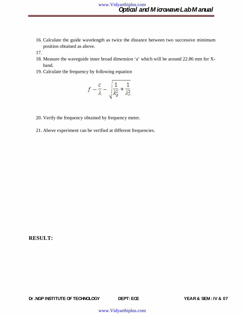
16. Calculate the guide wavelength as twice the distance between two successive minimum
position obtained as above. 17. 18. Measure the waveguide inner broad dimension ‘a’ which will be around 22.86 mm for X-
band. 19. Calculate the frequency by following equation
20. Verify the frequency obtained by frequency meter.
21. Above experiment can be verified at different frequencies.
RESULT:
www.Vidyarthiplus.com
www.Vidyarthiplus.com

Optical and Microwave Lab Manual
Dr.NGP INSTITUTE OF TECHNOLOGY DEPT: ECE YEAR & SEM : IV & 07
www.Vidyarthiplus.com
www.Vidyarthiplus.com

Optical and Microwave Lab Manual
Dr.NGP INSTITUTE OF TECHNOLOGY DEPT: ECE YEAR & SEM : IV & 07
Ex No: 7 IMPEDANCE MEASUREMENT BY SLOTTED LINE METHOD Date:
AIM:
To measure an unknown impedance using the smith chart.
EQUIPMENTS:
SNo. EQUIPMENT SPECIFICATION QUANTITY 1 Klystron power supply SKPS-610 1 2 Klystron tube with Klystron Mount 2K-25, XM-251 1
3 Isolator XI-621 1
4 Frequency meter XF-710 1
5 Variable Attenuator XA-520 1
6 Slotted section XS 651 1
7 Tunable Probe XP-655 1
8 VSWR Meter SW-115 1
9 Movable Short XT-4813 1
10 Wave Guide Stand XU-535 2
11 Matched Termination XL-400 1
12 S S Tuner XT 441
13 Oscilloscope -- 1
14 BNC Cable -- 1
15 Cooling Fan --- 1
THEORY:
The impedance at any point on a transmission line can be written in the form R+jX
www.Vidyarthiplus.com
www.Vidyarthiplus.com

Optical and Microwave Lab Manual
Dr.NGP INSTITUTE OF TECHNOLOGY DEPT: ECE YEAR & SEM : IV & 07
For comparison SWR can be calculated
Where
Reflection co-efficient
Z0= characteristics impedance of w/g at operating frequency
Z= load impedance. The measurement is performed in following way.
The unknown device is connected to the slotted line and the position of one minima is determined. The unknown device is replaced by movable short to the slotted line . Two successive minima positions are noted.The twice of the difference between minima position will be guidewave length. One of the minima is used as reference for impedance measurement .find the difference of reference minima and minima position obtained from unknown load. Let it be ‘d’. Take a smith chart , taking ‘1’ as centre, draw a circle of radius equal to S. mark a point on circumference of smith chart towards load side at a distance equal to d/g. join the centre with this point . find the point where it cut the drawn circle.the co-ordinates of this point will show the normalized impedance of load.
PROCEDURE:
1. Setup the components and equipments as shown in figure. 2. Setup variable attenuator at minimum attenuation position. 3. Keep the control knobs of VSWR meter as below:
Range - 50db position Input switch - Crystal low impedance Meter switch - Normal position Gain(Coarse & Fine)- Mid position
4. Keep the control knobs of Klystron power supply as below Beam voltage - ‘OFF’ Mod-switch -AM Beam Voltage knob-Fully anticlockwise
www.Vidyarthiplus.com
www.Vidyarthiplus.com

Optical and Microwave Lab Manual
Dr.NGP INSTITUTE OF TECHNOLOGY DEPT: ECE YEAR & SEM : IV & 07
Reflector Voltage- Fully clockwise AM- Amplitude knob- Around fully clockwise AM- Frequency knob – Around Mid position
5. Switch ‘ON’ the Klystron power supply, VSWR Meter and cooling fan switch. 6. Switch ‘ON’ the beam voltage switch and set beam voltage around 250V-300V with help
of beam voltage knob. 7. Adjust the reflector voltage to get some deflection in VSWR meter. 8. Maximize the deflection with AM amplitude and frequency control knob of power
supply. 9. Tune the plunger of Klystron Mount for maximum deflection. 10. Tune the reflector voltage knob for maximum deflection . 11. Tune the probe for maximum deflection in VSWR Meter. 12. Tune the frequency meter knob to get a ‘dip’ on the VSWR scale and note down the
frequency directly from frequency meter. 13. Keep the depth of pin S S. Tuner to around 3-4 mm and lock it. 14. Move the probe along the slotted line to get maximum deflection. 15. Adjust VSWR meter gain control knob and variable attenuator until the meter indicates
1.0 on the normal db SWR scale. 16. Move the probe to next minimum position and note down the SWR S0 on the scale .also
note down the probe position. Let it be ‘d’. 17. Remove the SS tuner and matched termination and place movable short at slotted line.
The plunger of short should be at zero. 18. Note the position of two successive minima position .let it be as d1 and d2 .Hence λg =
2(d1- d2). 19. Calculate
d -----
λg
20. Find out the normalized impedance as described in the theory section. 21. Repeat the same experiment for other frequency if required.
RESULT:
www.Vidyarthiplus.com
www.Vidyarthiplus.com