WA-9315 Complete Microwave Optics System - … Manual 012-13906A Microwave Optics System WA-9314C...
14
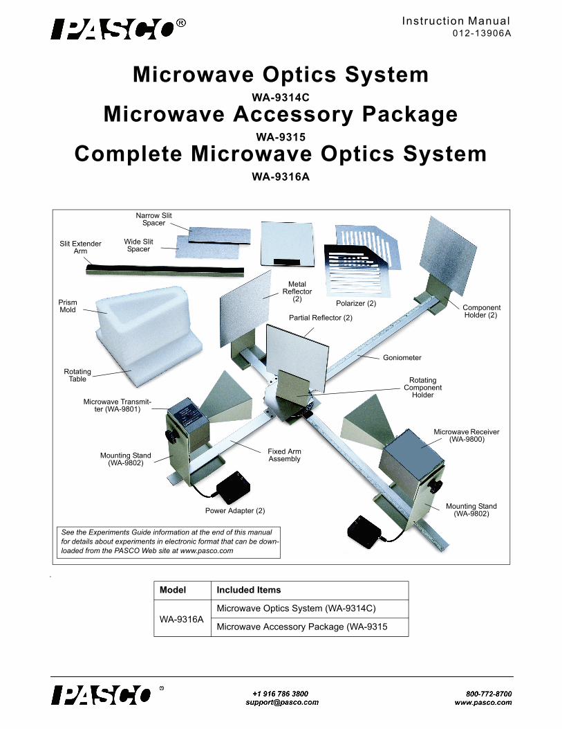
Instruction Manual 012-13906A Microwave Optics System WA-9314C Microwave Accessory Package WA-9315 Complete Microwave Optics System WA-9316A . Microwave Receiver (WA-9800) Microwave Transmit- ter (WA-9801) Mounting Stand (WA-9802) Mounting Stand (WA-9802) Power Adapter (2) Fixed Arm Assembly Goniometer Rotating Component Holder Partial Reflector (2) Metal Reflector (2) Polarizer (2) Slit Extender Arm Narrow Slit Spacer Wide Slit Spacer Prism Mold Rotating Table Component Holder (2) See the Experiments Guide information at the end of this manual for details about experiments in electronic format that can be down- loaded from the PASCO Web site at www.pasco.com Model Included Items WA-9316A Microwave Optics System (WA-9314C) Microwave Accessory Package (WA-9315
Transcript of WA-9315 Complete Microwave Optics System - … Manual 012-13906A Microwave Optics System WA-9314C...
Instruct ion Manual012-13906A
Microwave Optics SystemWA-9314C
Microwave Accessory PackageWA-9315
Complete Microwave Optics SystemWA-9316A
.
Microwave Receiver (WA-9800)
Microwave Transmit-ter (WA-9801)
Mounting Stand (WA-9802)
Mounting Stand (WA-9802)Power Adapter (2)
Fixed Arm Assembly
Goniometer
Rotating Component
Holder
Partial Reflector (2)
Metal Reflector
(2)Polarizer (2)
Slit Extender Arm
Narrow Slit Spacer
Wide Slit Spacer
Prism Mold
Rotating Table
Component Holder (2)
See the Experiments Guide information at the end of this manual for details about experiments in electronic format that can be down-loaded from the PASCO Web site at www.pasco.com
Model Included Items
WA-9316A
Microwave Optics System (WA-9314C)
Microwave Accessory Package (WA-9315
Microwave Opt ics System Introduct ion
2
.
*The Cubic Lattice contains 100 metal spheres in a 5 by 5 by 4 array.
Important Note
• CAUTION — Under some circumstances, microwaves can interfere with electronic medical devices. If you use a pacemaker, or other electronic medical device, check with your doctor or the manufacturer to be certain that low power microwaves at a frequency of 10.525 GHz will not interfere with its operation.
FCC Compliance This device complies with Part 15 of the FCC Rules.
Operation is subject to the following two conditions:
1. This device may not cause harmful interference.
2. This device must accept any interference received, including interferences that may cause undesired oper-ation.
Changes or modifications not expressly approved by PASCO scientific could void the user’s authority to operate the equipment.
IntroductionThere are many advantages to studying optical phenomena at microwave frequencies. Using a 2.85 centimeter microwave wavelength transforms the scale of the experiment. Microns become centimeters and variables obscured by the small scale of the tradition optics experiments are easily seen and manipulated. The PASCO Complete Microwave Optics Sys-tem is designed to take full advantage of these educational benefits. The Complete Microwave Optics System consists of the Microwave Optics System and the Microwave Acces-sory Package. The Microwave Optics System comes with a 2.85 centimeter wavelength microwave transmitter and a receiver with variable amplification from 1X to 30X. All the accessory equipment needed to investigate a variety of wave phenomena is also included.
This manual describes the operation and maintenance of the microwave equipment and presents an overview of many experiments. These experiments range from quantitative investigation of reflection and refraction to microwave mod-els of the Michelson and Fabry-Perot interferometers. Exper-iments for investigating Bragg diffraction and Brewster’s angle are included, but require the Microwave Accessory Package.
Microwave Optics System (WA-9314C) Microwave Optics System (WA-9314C)
Microwave Receiver WA-9800 Metal Reflectors (2)
Microwave Transmitter WA-9801 Partial Reflectors (2)
Mounting Stands (2) WA-9802 Polarizers (2)
Power Adapters (2) Slit Extender Arm
Goniometer Narrow Slit Spacer
Fixed Arm Assembly Wide Slit Spacer
Rotating Table Ethafoam Prism Mold
Component Holders (2) Styrene Pellets, not shown
Rotating Component Holder Tubular Plastic Bags (4), not shown
Microwave Accessory Package (WA-9315)
Cubic Lattice* (Bragg’s crystal model)
Polyethylene Panel
Recommended Equipment
PASCO Computer Interface
PASCO Data Acquisition Software
PASCO Voltage Sensor
Goniometer Angle Sensor
Angle Sensor Bracket
WA-9314C Ini t ia l Setup
3
The experiment write-ups are available in electronic format for download from the PASCO Web site (www.pasco.com).
Initial SetupTo attach the microwave Transmitter and Receiver to their respective stands prior to performing experiments, proceed as follows:
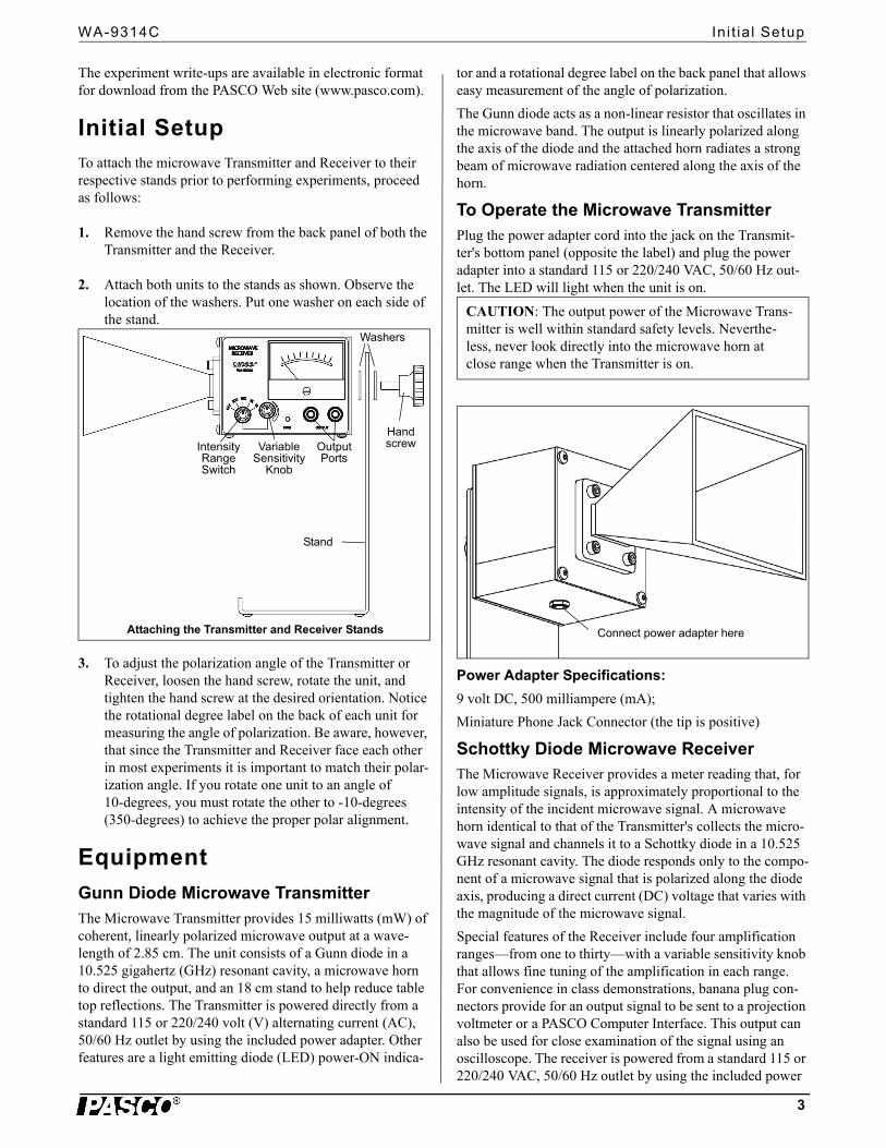
1. Remove the hand screw from the back panel of both the Transmitter and the Receiver.
2. Attach both units to the stands as shown. Observe the location of the washers. Put one washer on each side of the stand.
3. To adjust the polarization angle of the Transmitter or Receiver, loosen the hand screw, rotate the unit, and tighten the hand screw at the desired orientation. Notice the rotational degree label on the back of each unit for measuring the angle of polarization. Be aware, however, that since the Transmitter and Receiver face each other in most experiments it is important to match their polar-ization angle. If you rotate one unit to an angle of 10-degrees, you must rotate the other to -10-degrees (350-degrees) to achieve the proper polar alignment.
Equipment
Gunn Diode Microwave TransmitterThe Microwave Transmitter provides 15 milliwatts (mW) of coherent, linearly polarized microwave output at a wave-length of 2.85 cm. The unit consists of a Gunn diode in a 10.525 gigahertz (GHz) resonant cavity, a microwave horn to direct the output, and an 18 cm stand to help reduce table top reflections. The Transmitter is powered directly from a standard 115 or 220/240 volt (V) alternating current (AC), 50/60 Hz outlet by using the included power adapter. Other features are a light emitting diode (LED) power-ON indica-
tor and a rotational degree label on the back panel that allows easy measurement of the angle of polarization.
The Gunn diode acts as a non-linear resistor that oscillates in the microwave band. The output is linearly polarized along the axis of the diode and the attached horn radiates a strong beam of microwave radiation centered along the axis of the horn.
To Operate the Microwave Transmitter
Connect power adapter here
Plug the power adapter cord into the jack on the Transmit-ter's bottom panel (opposite the label) and plug the power adapter into a standard 115 or 220/240 VAC, 50/60 Hz out-let. The LED will light when the unit is on.
Power Adapter Specifications:
9 volt DC, 500 milliampere (mA);
Miniature Phone Jack Connector (the tip is positive)
Schottky Diode Microwave ReceiverThe Microwave Receiver provides a meter reading that, for low amplitude signals, is approximately proportional to the intensity of the incident microwave signal. A microwave horn identical to that of the Transmitter's collects the micro-wave signal and channels it to a Schottky diode in a 10.525 GHz resonant cavity. The diode responds only to the compo-nent of a microwave signal that is polarized along the diode axis, producing a direct current (DC) voltage that varies with the magnitude of the microwave signal.
Special features of the Receiver include four amplification ranges—from one to thirty—with a variable sensitivity knob that allows fine tuning of the amplification in each range. For convenience in class demonstrations, banana plug con-nectors provide for an output signal to be sent to a projection voltmeter or a PASCO Computer Interface. This output can also be used for close examination of the signal using an oscilloscope. The receiver is powered from a standard 115 or 220/240 VAC, 50/60 Hz outlet by using the included power
Hand screw
Washers
Intensity Range Switch
Variable Sensitivity
Knob
Output Ports
Stand
Attaching the Transmitter and Receiver Stands
CAUTION: The output power of the Microwave Trans-mitter is well within standard safety levels. Neverthe-less, never look directly into the microwave horn at close range when the Transmitter is on.
Microwave Opt ics System 012-13906A Accessory Equipment
4
adapter. and has an LED power-ON indicator. As with the Transmitter, an 18 cm high mount minimizes table top reflections, and a rotational degree label on the back panel allows convenient measurements of the polarization angle.
The connector labeled “EXTERNAL ANTENNA” on the side of the Receiver is for an optional microwave detector probe. Such a probe works the same as the Receiver except it has no horn or resonant cavity. A detector probe is particu-larly convenient for examining wave patterns in which the horn might get in the way
.
To Operate The Microwave Receiver:Start with the INTENSITY selection switch in the OFF posi-tion.
1. Plug the power adapter cord into the jack labeled “9VDC@500mA” on the Receiver’s side panel (oppo-site the label) and plug the power adapter into a standard 115 or 220/240 VAC, 50/60 Hz outlet. The “PWR” LED on the label side will light when the INTENSITY selec-tion switch is turned from OFF to one of the amplifica-tion levels.
2. Turn the INTENSITY selection switch from OFF to 30X, the lowest amplification level. The power-ON indicator LED should light.
3. Point the microwave horn toward the incident micro-wave signal. Unless polarization effects are under inves-tigation, adjust the polarization angles of the Transmitter and Receiver to the same orientation (e.g., both horns vertically, or both horns horizontally).
4. Adjust the VARIABLE SENSITIVITY knob to attain a meter reading near midscale. If no deflection of the meter occurs, increase the amplification by turning the INTENSITY selection switch clockwise. Remember, always multiply your meter reading by the appropriate INTENSITY selection (30X, 10X, 3X, or 1X) if you
want to make a quantitative comparison of measure-ments taken at different INTENSITY settings.
Adjusting the Receiver
Meter mechanical zero adjustment:
1. Turn the INTENSITY switch to OFF.
The mechanical zero adjustment is located on the meter, cen-tered just below the meter face.
2. With the meter level and in the horizontal position, use a small (1/8”) flat-blade screwdriver to adjust the meter needle to read as close to 0 as possible.
Accessory EquipmentAccessory equipment for the Microwave Optics System includes the following:
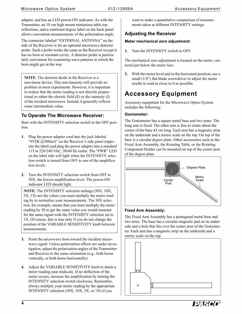
Goniometer:
The Goniometer has a square metal base and two arms. The long arm is fixed. The other arm is free to rotate about the center of the base 43 cm long. Each arm has a magnetic strip on the underside and a metric scale on the top. On top of the base is a circular degree plate. Other accessories such as the Fixed Arm Assembly, the Rotating Table, or the Rotating Component Holder can be mounted on top of the center post of the degree plate.
Fixed Arm Assembly:
The Fixed Arm Assembly has a pentagonal metal base and two arms. The base has a circular magnetic pad on its under-side and a hole that fits over the center post of the Goniome-ter. Each arm has a magnetic strip on the underside and a metric scale on the top.
NOTE: The detector diode in the Receiver is a non-linear device. This non-linearity will provide no problem in most experiments. However, it is important to realize that the meter reading is not directly propor-tional to either the electric field (E) or the intensity (I) of the incident microwave. Instead, it generally reflects some intermediate value.
NOTE: The INTENSITY selection settings (30X, 10X, 3X, 1X) are the values you must multiply the meter read-ing by to normalize your measurements. The 30X selec-tion, for example, means that you must multiply the meter reading by 30 to get the same value you would measure for the same signal with the INTENSITY selection set to 1X. Of course, this is true only if you do not change the position of the VARIABLE SENSITIVITY knob between measurements.
Degree Plate
Metric ScaleCenter
Post
WA-9314C Accessory Equipment
5
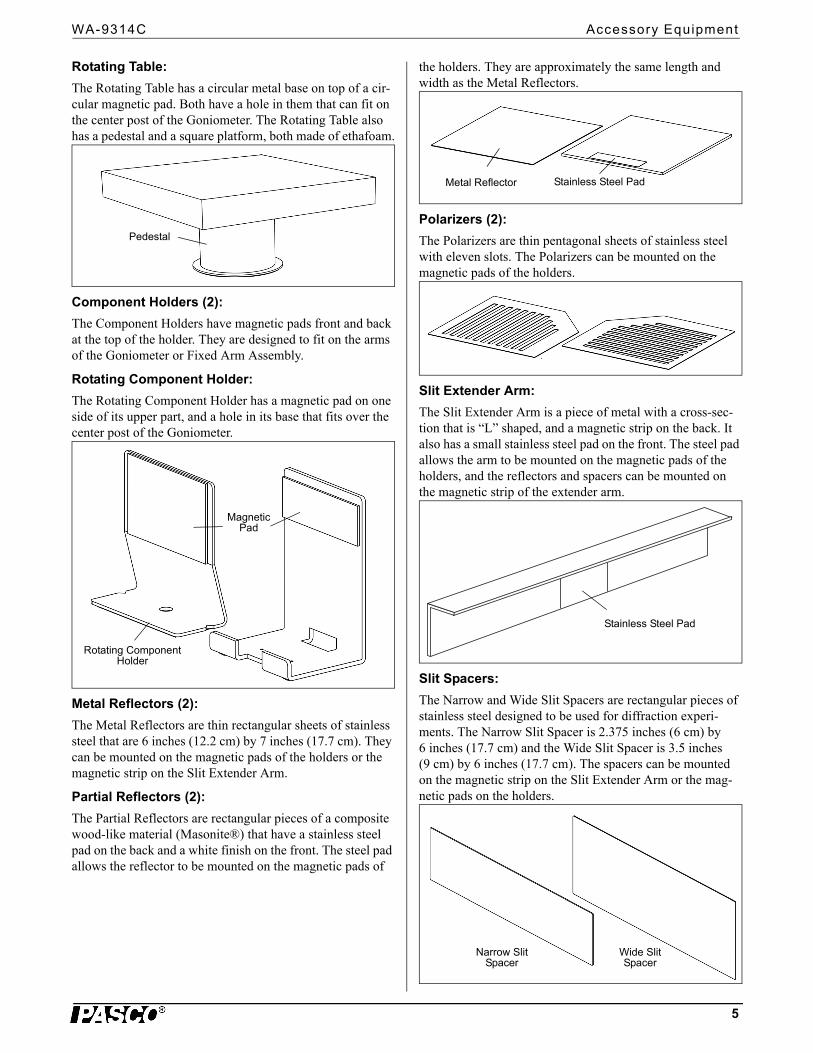
Rotating Table:
The Rotating Table has a circular metal base on top of a cir-cular magnetic pad. Both have a hole in them that can fit on the center post of the Goniometer. The Rotating Table also has a pedestal and a square platform, both made of ethafoam.
Component Holders (2):
The Component Holders have magnetic pads front and back at the top of the holder. They are designed to fit on the arms of the Goniometer or Fixed Arm Assembly.
Rotating Component Holder:
The Rotating Component Holder has a magnetic pad on one side of its upper part, and a hole in its base that fits over the center post of the Goniometer.
Metal Reflectors (2):
The Metal Reflectors are thin rectangular sheets of stainless steel that are 6 inches (12.2 cm) by 7 inches (17.7 cm). They can be mounted on the magnetic pads of the holders or the magnetic strip on the Slit Extender Arm.
Partial Reflectors (2):
The Partial Reflectors are rectangular pieces of a composite wood-like material (Masonite®) that have a stainless steel pad on the back and a white finish on the front. The steel pad allows the reflector to be mounted on the magnetic pads of
the holders. They are approximately the same length and width as the Metal Reflectors.
Polarizers (2):
The Polarizers are thin pentagonal sheets of stainless steel with eleven slots. The Polarizers can be mounted on the magnetic pads of the holders.
Slit Extender Arm:
The Slit Extender Arm is a piece of metal with a cross-sec-tion that is “L” shaped, and a magnetic strip on the back. It also has a small stainless steel pad on the front. The steel pad allows the arm to be mounted on the magnetic pads of the holders, and the reflectors and spacers can be mounted on the magnetic strip of the extender arm.
Slit Spacers:
The Narrow and Wide Slit Spacers are rectangular pieces of stainless steel designed to be used for diffraction experi-ments. The Narrow Slit Spacer is 2.375 inches (6 cm) by 6 inches (17.7 cm) and the Wide Slit Spacer is 3.5 inches (9 cm) by 6 inches (17.7 cm). The spacers can be mounted on the magnetic strip on the Slit Extender Arm or the mag-netic pads on the holders.
Pedestal
Magnetic Pad
Rotating Component Holder
Stainless Steel PadMetal Reflector
Stainless Steel Pad
Narrow Slit Spacer
Wide Slit Spacer
Microwave Opt ics System 012-13906A Assembl ing Equipment for Exper iments
6
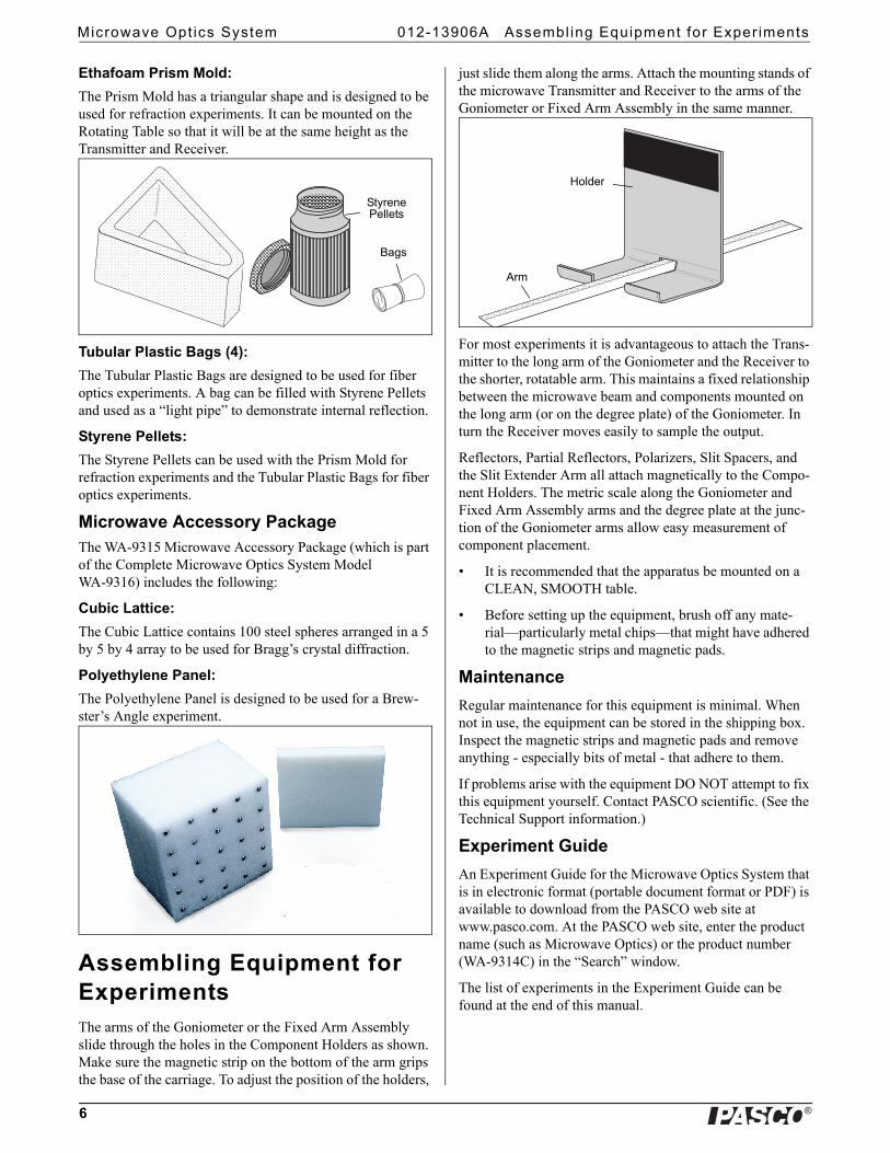
Ethafoam Prism Mold:
The Prism Mold has a triangular shape and is designed to be used for refraction experiments. It can be mounted on the Rotating Table so that it will be at the same height as the Transmitter and Receiver.
Tubular Plastic Bags (4):
The Tubular Plastic Bags are designed to be used for fiber optics experiments. A bag can be filled with Styrene Pellets and used as a “light pipe” to demonstrate internal reflection.
Styrene Pellets:
The Styrene Pellets can be used with the Prism Mold for refraction experiments and the Tubular Plastic Bags for fiber optics experiments.
Microwave Accessory PackageThe WA-9315 Microwave Accessory Package (which is part of the Complete Microwave Optics System Model WA-9316) includes the following:
Cubic Lattice:
The Cubic Lattice contains 100 steel spheres arranged in a 5 by 5 by 4 array to be used for Bragg’s crystal diffraction.
Polyethylene Panel:
The Polyethylene Panel is designed to be used for a Brew-ster’s Angle experiment.
Assembling Equipment for ExperimentsThe arms of the Goniometer or the Fixed Arm Assembly slide through the holes in the Component Holders as shown. Make sure the magnetic strip on the bottom of the arm grips the base of the carriage. To adjust the position of the holders,
just slide them along the arms. Attach the mounting stands of the microwave Transmitter and Receiver to the arms of the Goniometer or Fixed Arm Assembly in the same manner.
For most experiments it is advantageous to attach the Trans-mitter to the long arm of the Goniometer and the Receiver to the shorter, rotatable arm. This maintains a fixed relationship between the microwave beam and components mounted on the long arm (or on the degree plate) of the Goniometer. In turn the Receiver moves easily to sample the output.
Reflectors, Partial Reflectors, Polarizers, Slit Spacers, and the Slit Extender Arm all attach magnetically to the Compo-nent Holders. The metric scale along the Goniometer and Fixed Arm Assembly arms and the degree plate at the junc-tion of the Goniometer arms allow easy measurement of component placement.
• It is recommended that the apparatus be mounted on a CLEAN, SMOOTH table.
• Before setting up the equipment, brush off any mate-rial—particularly metal chips—that might have adhered to the magnetic strips and magnetic pads.
Maintenance
Regular maintenance for this equipment is minimal. When not in use, the equipment can be stored in the shipping box. Inspect the magnetic strips and magnetic pads and remove anything - especially bits of metal - that adhere to them.
If problems arise with the equipment DO NOT attempt to fix this equipment yourself. Contact PASCO scientific. (See the Technical Support information.)
Experiment Guide
An Experiment Guide for the Microwave Optics System that is in electronic format (portable document format or PDF) is available to download from the PASCO web site at www.pasco.com. At the PASCO web site, enter the product name (such as Microwave Optics) or the product number (WA-9314C) in the “Search” window.
The list of experiments in the Experiment Guide can be found at the end of this manual.
Styrene Pellets
Bags
Holder
Arm

WA-9314C Technical Support
7
Activity 1: Introduction to the Microwave Optics System
Activity 1 (see page 9) is an example of the worksheet style of the experiment write-ups.
Technical SupportFor assistance with any PASCO product, contact PASCO at:
For the latest information about the Complete Microwave Optics System or its accessories,
go to the PASCO web site at www.pasco.com and enter the model number or the product name in the search window.
Limited Warranty For a description of the product warranty, see the PASCO catalog. Copyright The PASCO scientific Instruction Manual is copyrighted with all rights reserved. Permission is granted to non-profit educational institutions for reproduction of any part of this manual, providing the reproductions are used only in their laborato-ries and classrooms, and are not sold for profit. Reproduction under any other circumstances, without the written consent of PASCO sci-entific, is prohibited. Trademarks PASCO, PASCO Capstone, PASPORT, SPARK Science Learning System, SPARK SLS, and SPARKvue are trademarks or registered trademarks of PASCO sci-entific, in the United States and/or in other countries. For more infor-mation visit www.pasco.com/legal.
Product End of Life Disposal Instructions:
This electronic product is subject to disposal and recycling regulations that vary by country and region. It is your responsibility to recycle your electronic equipment per your local environmental laws and regulations to ensure that it will be recycled in a manner that protects human health and the environment. To find out where you can drop off your waste equipment for recycling, please contact your local waste recycle/disposal service, or the place where you pur-chased the product.
The European Union WEEE (Waste Elec-tronic and Electrical Equipment) symbol (to the right) and on the product or its packaging indicates that this product must not be disposed of in a standard waste con-tainer.
Address: PASCO scientific10101 Foothills Blvd.Roseville, CA 95747-7100
Phone: +1 916 786 3800 (worldwide)800-772-8700 (U.S.)
E-mail: [email protected]
Web www.pasco.com
Microwave Opt ics System Technical Support
8
WA-9314C Act iv i ty : Introduct ion to the Microwave Opt ics System
9
Activity: Introduction to the Microwave Optics System
Equipment Needed:
Purpose
This activity gives an introduction to the Microwave Optics System which may prove helpful in learning to use the equipment effectively and in understanding the significance of measurements made with this equipment.
Procedure
R
Figure 1: Equipment SetupT
RT
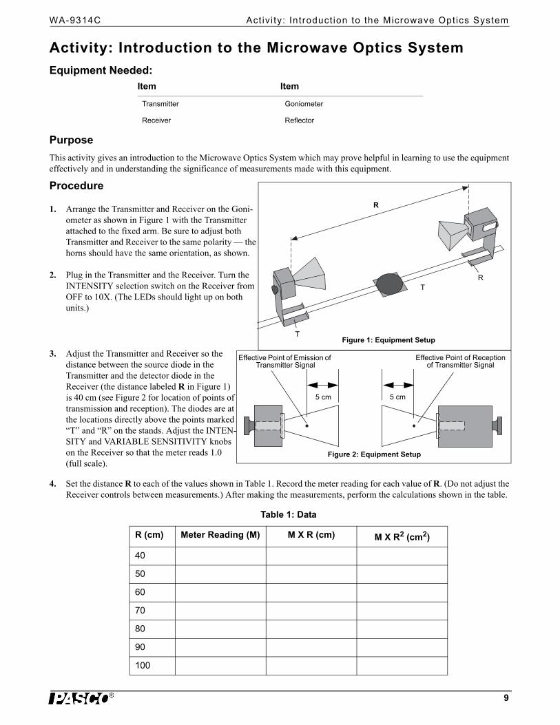
1. Arrange the Transmitter and Receiver on the Goni-ometer as shown in Figure 1 with the Transmitter attached to the fixed arm. Be sure to adjust both Transmitter and Receiver to the same polarity — the horns should have the same orientation, as shown.
2. Plug in the Transmitter and the Receiver. Turn the INTENSITY selection switch on the Receiver from OFF to 10X. (The LEDs should light up on both units.)
3. Adjust the Transmitter and Receiver so the distance between the source diode in the Transmitter and the detector diode in the Receiver (the distance labeled R in Figure 1) is 40 cm (see Figure 2 for location of points of transmission and reception). The diodes are at the locations directly above the points marked “T” and “R” on the stands. Adjust the INTEN-SITY and VARIABLE SENSITIVITY knobs on the Receiver so that the meter reads 1.0 (full scale).
4. Set the distance R to each of the values shown in Table 1. Record the meter reading for each value of R. (Do not adjust the Receiver controls between measurements.) After making the measurements, perform the calculations shown in the table.
Item Item
Transmitter Goniometer
Receiver Reflector
Table 1: Data
R (cm) Meter Reading (M) M X R (cm) M X R2 (cm2)
40
50
60
70
80
90
100
Effective Point of Emission of Transmitter Signal
Effective Point of Reception of Transmitter Signal
5 cm 5 cm
Figure 2: Equipment Setup

Microwave Opt ics System Act iv i ty : Introduct ion to the Microwave Opt ics System
10
5. Set R to some value between 70 and 90 cm. While watching the meter, slowly decrease the distance between the Trans-mitter and Receiver. Does the meter deflection increase steadily as the distance decreases?
6. Set R to between 50 and 90 cm. Move a Reflector, its plane parallel to the axis of the microwave beam, toward and away from the beam axis, as shown in Figure 3. Observe the meter readings. Can you explain your observations in steps 5 and 6? (Don’t worry if you can’t; you will have a chance to investigate these phenomena more closely in other experiments.) For now just be aware of the following:
7. Loosen the hand screw on the back of the Receiver and rotate the Receiver as shown in Figure 4. This varies the polarity of maximum detection. (Look into the receiver horn and notice the alignment of the detector diode.) Observe the meter readings through a full 360 degree rotation of the horn. A small mirror may be helpful to view the meter reading as the receiver is turned. At what polarity does the Receiver detect no signal?
NOTE: Try rotating the Transmitter horn as well. When finished, reset the Transmitter and Receiver so their polarities match (e.g., both horns are horizontal or both horns are vertical).
8. Position the Transmitter so the output surface of the horn is cen-tered directly over the center of the Degree Plate of the Goni-ometer arm (see Figure 5). With the Receiver directly facing the Transmitter and as far back on the Goniometer arm as possible, adjust the Receiver controls for a meter reading of 1.0. Then rotate the rotatable arm of the Goniometer as shown in the fig-ure. Set the angle of rotation (measured relative to the 180-degree point on the degree scale) to each of the values shown in Table 2, and record the meter reading at each setting
.
Table 2: Data
Angle of Receiver
Meter Reading
Angle of Receiver
Meter Reading
Angle of Receiver
Meter Reading
90° 160 230
100 170 240
110 180 250
120 190 260
130 200 270
140 210
150 220
Reflector
Figure 3: Reflections
IMPORTANT: Reflections from nearby objects, including the table top, can affect the results of your microwave exper-iments. To reduce the effects of extraneous reflections, keep your experiment table clear of all objects, especially metal objects, other than those components required for the current experiment.
Figure 4: Polarization
Figure 5: Signal Distribution
Angle = 180°

WA-9314C Act iv i ty : Introduct ion to the Microwave Opt ics System
11
Questions
1. The electric field of an electromagnetic wave is inversely proportional to the distance from the wave source, (i.e., E = 1/R). Use your data from step 4 of the experiment to determine if the meter reading of the Receiver is directly propor-tional to the electric field of the wave.
2. The intensity of an electromagnetic wave is inversely proportional to the square of the distance from the wave source (i.e., I = 1/R2). Use your data from step 4 of the experiment to determine if the meter reading of the Receiver is directly propor-tional to the intensity of the wave.
3. Considering your results in step 7, to what extent can the Transmitter output be considered a spherical wave? A plane wave?
• (See the Teacher’s Guide on the next page for typical results and answers to the questions.)
Microwave Opt ics System Teacher ’s Guide
12
Teacher’s Guide
Activity 1: Introduction to the Microwave Optics System
Notes on the Procedure
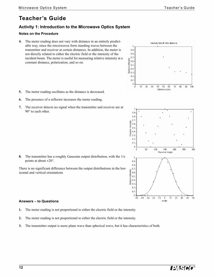
4. The meter reading does not vary with distance in an entirely predict-able way, since the microwaves form standing waves between the transmitter and receiver at certain distances. In addition, the meter is not directly related to either the electric field or the intensity of the incident beam. The meter is useful for measuring relative intensity at a constant distance, polarization, and so on.
5. The meter reading oscillates as the distance is decreased.
6. The presence of a reflector increases the meter reading.
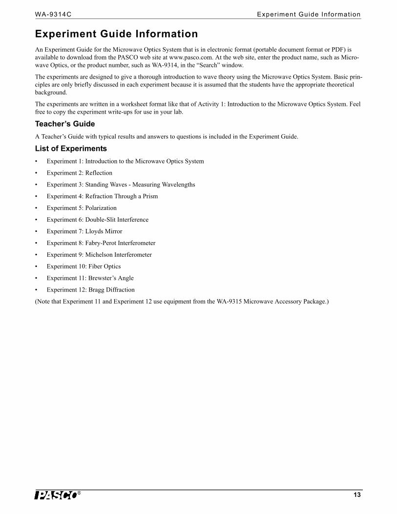
7. The receiver detects no signal when the transmitter and receiver are at 90° to each other.
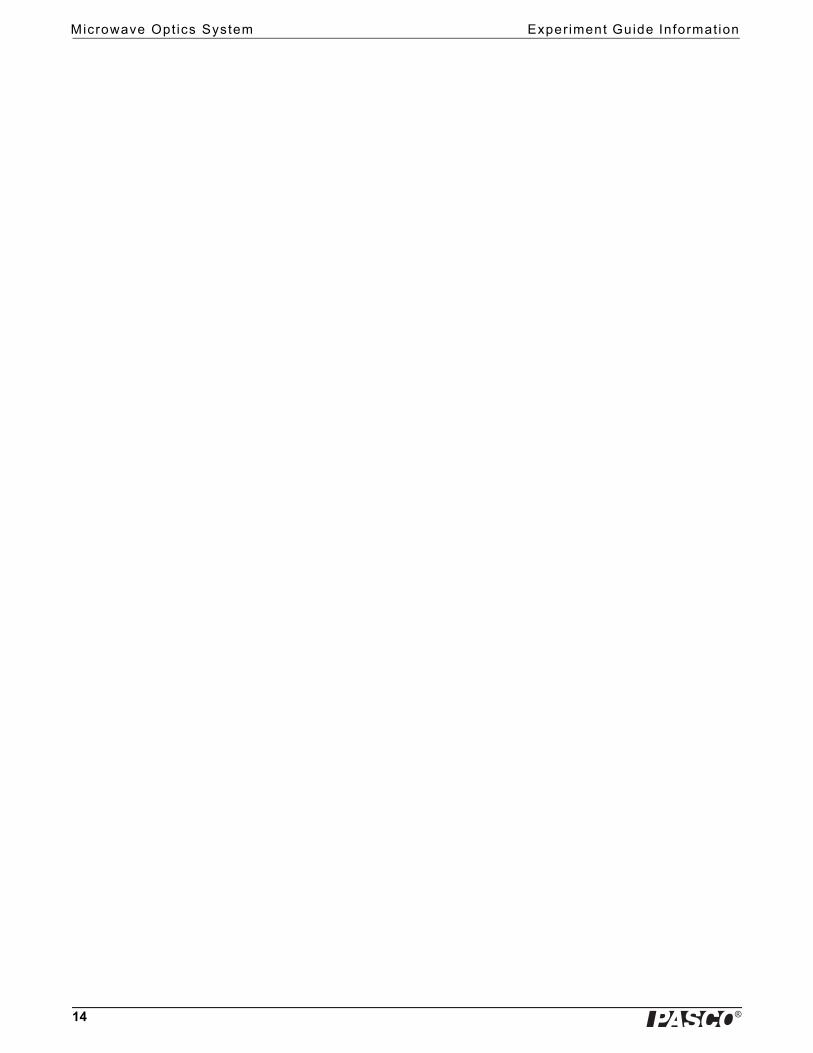
8. The transmitter has a roughly Gaussian output distribution, with the 1/e points at about ±20°.
There is no significant difference between the output distributions in the hor-izontal and vertical orientations
Answers – to Questions
1. The meter reading is not proportional to either the electric field or the intensity.
2. The meter reading is not proportional to either the electric field or the intensity.
3. The transmitter output is more plane wave than spherical wave, but it has characteristics of both.
WA-9314C Exper iment Guide Informat ion
13
Experiment Guide InformationAn Experiment Guide for the Microwave Optics System that is in electronic format (portable document format or PDF) is available to download from the PASCO web site at www.pasco.com. At the web site, enter the product name, such as Micro-wave Optics, or the product number, such as WA-9314, in the “Search” window.
The experiments are designed to give a thorough introduction to wave theory using the Microwave Optics System. Basic prin-ciples are only briefly discussed in each experiment because it is assumed that the students have the appropriate theoretical background.
The experiments are written in a worksheet format like that of Activity 1: Introduction to the Microwave Optics System. Feel free to copy the experiment write-ups for use in your lab.
Teacher’s Guide
A Teacher’s Guide with typical results and answers to questions is included in the Experiment Guide.
List of Experiments
• Experiment 1: Introduction to the Microwave Optics System
• Experiment 2: Reflection
• Experiment 3: Standing Waves - Measuring Wavelengths
• Experiment 4: Refraction Through a Prism
• Experiment 5: Polarization
• Experiment 6: Double-Slit Interference
• Experiment 7: Lloyds Mirror
• Experiment 8: Fabry-Perot Interferometer
• Experiment 9: Michelson Interferometer
• Experiment 10: Fiber Optics
• Experiment 11: Brewster’s Angle
• Experiment 12: Bragg Diffraction
(Note that Experiment 11 and Experiment 12 use equipment from the WA-9315 Microwave Accessory Package.)
Microwave Opt ics System Exper iment Guide Informat ion
14