E5CN-H, E5AN-H, E5EN-H Digital Controllers User's Manual
376
E5CN-H E5CN-H E5CN-H E5AN-H E5AN-H E5AN-H E5EN-H E5EN-H E5EN-H User's Manual Advanced Type Digital Controllers Cat. No. H157-E1-03 PF A/M SUB3 HA SUB2 OUT2 OUT1 CMW RSP STOP MANU SUB1 MV SV PV Ir E5AN-H Ir PF A/M MV SV PV SUB2 SUB3 STOP OUT1 RSP MANU CMW OUT2 SUB1 HA E5EN-H E5CN-H SUB1 OUT1 OUT2 STOP CWM MANU SUB2 SUB3 HA
-
Upload
truongthuy -
Category
Documents
-
view
274 -
download
9
Transcript of E5CN-H, E5AN-H, E5EN-H Digital Controllers User's Manual

E5CN-HE5CN-HE5CN-HE5AN-HE5AN-HE5AN-HE5EN-HE5EN-HE5EN-H
User's ManualAdvanced Type
Digital Controllers
Cat. No. H157-E1-03
PFA/M
SUB3
HA
SUB2
OUT2
OUT1
CMW
RSP STOP
MANU
SUB1
MV
SV
PV
Ir
E5AN-H
Ir
PFA/M
MV
SV
PV
SUB2
SUB3
STOPOUT1
RSP
MANUCMWOUT2
SUB1
HA
E5EN-HE5CN-H
SUB1
OUT1
OUT2
STOP
CWM MANU
SUB2SUB3HA


E5CN-HE5AN-HE5EN-HDigital ControllersUser’s Manual
Advanced TypeRevised January 2011

iv

PrefaceThe E5CN-H, E5AN-H, and E5EN-H are Digital Controllers. The main functions and characteristics ofthese Digital Controllers are as follows:
• Use the universal inputs to input from thermocouples or temperature-resistance thermometers, or to input analog voltage or analog currentinputs.
• Either standard or heating/cooling control can be performed. • Both auto-tuning and self-tuning are supported.• Event inputs can be used to switch banks, switch between RUN and
STOP status, switch between automatic and manual operation, start/resetthe simple program function, and perform other operations.
• Heater burnout detection, heater short (HS) alarms, and heater overcur-rent (OC) functions are supported. (Applicable to E5CN-H, E5AN-H, andE5EN-H models with heater burnout detection function.)
• Communications are supported. (Applicable to E5CN-H, E5AN-H, andE5EN-H models with communications.)
• User calibration of the sensor input is supported.• User calibration of transfer output is supported. (Applicable to E5CN-H,
E5AN-H, and E5EN-H models with transfer outputs.) • Use position-proportional control. (Applicable to the E5AN-H and E5EN-
H.) • Use a remote SP input (Applicable to the E5AN-H and E5EN-H.) • The structure is waterproof (IP66).• Conforms to UL, CSA, and IEC safety standards and EMC Directive.• The PV display color can be switched to make process status easy to
understand at a glance.
This manual describes the E5CN-H, E5AN-H, and E5EN-H. Read this manual thoroughly and be sureyou understand it before attempting to use the Digital Controller and use the Digital Controller correctlyaccording to the information provided. Keep this manual in a safe place for easy reference. Refer to thefollowing manual for further information on communications: E5CN-H/E5AN-H/E5EN-H Digital Control-lers Communications Manual Advanced Type (Cat. No. H159).
Visual AidsThe following headings appear in the left column of the manual to help you locate different types ofinformation.
Note Indicates information of particular interest for efficient and convenient opera-tion of the product.
1,2,3... 1. Indicates lists of one sort or another, such as procedures, checklists, etc.
OMRON, 2008All rights reserved. No part of this publication may be reproduced, stored in a retrieval system, or transmitted, in any form, orby any means, mechanical, electronic, photocopying, recording, or otherwise, without the prior written permission ofOMRON.
No patent liability is assumed with respect to the use of the information contained herein. Moreover, because OMRON is con-stantly striving to improve its high-quality products, the information contained in this manual is subject to change withoutnotice. Every precaution has been taken in the preparation of this manual. Nevertheless, OMRON assumes no responsibilityfor errors or omissions. Neither is any liability assumed for damages resulting from the use of the information contained inthis publication.
v

Read and Understand this ManualPlease read and understand this manual before using the products. Please consult your OMRON representative if you have any questions or comments.
Warranty, Limitations of LiabilityWARRANTYOMRON's exclusive warranty is that the products are free from defects in materials and workmanship for a period of one year (or other period if specified) from date of sale by OMRON.OMRON MAKES NO WARRANTY OR REPRESENTATION, EXPRESS OR IMPLIED, REGARDING NON-INFRINGEMENT, MERCHANTABILITY, OR FITNESS FOR PARTICULAR PURPOSE OF THE PRODUCTS. ANY BUYER OR USER ACKNOWLEDGES THAT THE BUYER OR USER ALONE HAS DETERMINED THAT THE PRODUCTS WILL SUITABLY MEET THE REQUIREMENTS OF THEIR INTENDED USE. OMRON DISCLAIMS ALL OTHER WARRANTIES, EXPRESS OR IMPLIED.
LIMITATIONS OF LIABILITYOMRON SHALL NOT BE RESPONSIBLE FOR SPECIAL, INDIRECT, OR CONSEQUENTIAL DAMAGES, LOSS OF PROFITS OR COMMERCIAL LOSS IN ANY WAY CONNECTED WITH THE PRODUCTS, WHETHER SUCH CLAIM IS BASED ON CONTRACT, WARRANTY, NEGLIGENCE, OR STRICT LIABILITY.In no event shall the responsibility of OMRON for any act exceed the individual price of the product on which liability is asserted. IN NO EVENT SHALL OMRON BE RESPONSIBLE FOR WARRANTY, REPAIR, OR OTHER CLAIMS REGARDING THE PRODUCTS UNLESS OMRON'S ANALYSIS CONFIRMS THAT THE PRODUCTS WERE PROPERLY HANDLED, STORED, INSTALLED, AND MAINTAINED AND NOT SUBJECT TO CONTAMINATION, ABUSE, MISUSE, OR INAPPROPRIATE MODIFICATION OR REPAIR.
Application ConsiderationsSUITABILITY FOR USEOMRON shall not be responsible for conformity with any standards, codes, or regulations that apply to the combination of the products in the customer's application or use of the products.At the customer's request, OMRON will provide applicable third party certification documents identifying ratings and limitations of use that apply to the products. This information by itself is not sufficient for a complete determination of the suitability of the products in combination with the end product, machine, system, or other application or use.The following are some examples of applications for which particular attention must be given. This is not intended to be an exhaustive list of all possible uses of the products, nor is it intended to imply that the uses listed may be suitable for the products:• Outdoor use, uses involving potential chemical contamination or electrical interference, or conditions or
uses not described in this manual.• Nuclear energy control systems, combustion systems, railroad systems, aviation systems, medical
equipment, amusement machines, vehicles, safety equipment, and installations subject to separate industry or government regulations.
• Systems, machines, and equipment that could present a risk to life or property. Please know and observe all prohibitions of use applicable to the products.NEVER USE THE PRODUCTS FOR AN APPLICATION INVOLVING SERIOUS RISK TO LIFE OR PROPERTY WITHOUT ENSURING THAT THE SYSTEM AS A WHOLE HAS BEEN DESIGNED TO ADDRESS THE RISKS, AND THAT THE OMRON PRODUCTS ARE PROPERLY RATED AND INSTALLED FOR THE INTENDED USE WITHIN THE OVERALL EQUIPMENT OR SYSTEM.
PROGRAMMABLE PRODUCTS OMRON shall not be responsible for the user's programming of a programmable product, or any consequence thereof.
vi

DisclaimersCHANGE IN SPECIFICATIONSProduct specifications and accessories may be changed at any time based on improvements and other reasons.It is our practice to change model numbers when published ratings or features are changed, or when significant construction changes are made. However, some specifications of the products may be changed without any notice. When in doubt, special model numbers may be assigned to fix or establish key specifications for your application on your request. Please consult with your OMRON representative at any time to confirm actual specifications of purchased products.
DIMENSIONS AND WEIGHTS Dimensions and weights are nominal and are not to be used for manufacturing purposes, even when tolerances are shown.
PERFORMANCE DATA Performance data given in this manual is provided as a guide for the user in determining suitability and does not constitute a warranty. It may represent the result of OMRON's test conditions, and the users must correlate it to actual application requirements. Actual performance is subject to the OMRON Warranty and Limitations of Liability.
ERRORS AND OMISSIONSThe information in this manual has been carefully checked and is believed to be accurate; however, no responsibility is assumed for clerical, typographical, or proofreading errors, or omissions.
vii

Definition of Precautionary InformationThe following notation is used in this manual to provide precautions requiredto ensure safe usage of the product.
The safety precautions that are provided are extremely important to safety.Always read and heed the information provided in all safety precautions.
The following notation is used.
Symbols
Safety Precautions
CAUTIONIndicates a potentially hazardous situation which, if not avoided, is likely to result in minor or moderate injury or in property damage.
Symbol Meaning
Caution
General Caution Indicates non-specific general cautions, warnings, and dangers.
Electrical Shock CautionIndicates possibility of electric shock under specific conditions.
ProhibitionGeneral ProhibitionIndicates non-specific general prohibitions.
Mandatory Caution
General CautionIndicates non-specific general cautions, warnings, and dangers.
viii

Safety Precautions
Note 1: An SELV circuit is one separated from the power supply with double
insulation or reinforced insulation, that does not exceed 30 V r.m.s.
and 42.4 V peak or 60 VDC.
Note 2: A class 2 power supply is one tested and certified by UL as having
the current and voltage of the secondary output restricted to specific
levels.
CAUTION
Do not touch the terminals while power is being supplied.Doing so may occasionally result in minor injury due to electric shock.
Do not allow pieces of metal, wire clippings, or fine metallic shav-ings or filings from installation to enter the product. Doing so may occasionally result in electric shock, fire, or malfunction.
Do not use the product where subject to flammable or explosive gas. Otherwise, minor injury from explosion may occasionally occur.
Never disassemble, modify, or repair the product or touch any of the internal parts. Minor electric shock, fire, or malfunction may occasionally occur.
CAUTION - Risk of Fire and Electric Shocka) This product is UL listed as Open Type Process Control
Equipment. It must be mounted in an enclosure that does not allow fire to escape externally.
b) When using more than one shutoff switch, always turn OFF all the shutoff switches to ensure that no power is being supplied before servicing the product.
c) Signal inputs are SELV, limited energy. (See note 1.)d) Caution: To reduce the risk of fire or electric shock, do not
interconnect the outputs of different Class 2 circuits. (See note 2.)
If the output relays are used past their life expectancy, contact fusing or burning may occasionally occur.Always consider the application conditions and use the output relays within their rated load and electrical life expectancy. The life expectancy of output relays varies considerably with the output load and switching conditions.
ix

CAUTION
Tighten the terminal screws to between 0.74 and 0.90 N·m. Loose screws may occasionally result in fire.
Set the parameters of the product so that they are suitable for the system being controlled. If they are not suitable, unexpected operation may occasionally result in property damage or accidents.
A malfunction in the Digital Controller may occasionally make control operations impossible or prevent alarm outputs, resulting in property damage. To maintain safety in the event of malfunction of the Digital Controller, take appropriate safety measures, such as installing a monitoring device on a separate line.
When inserting the body of the Digital Controller into the case, confirm that the hooks on the top and bottom are securely engaged with the case. If the body of the Digital Controller is not inserted properly, faulty contact in the terminal section or reduced water resistance may occasionally result in fire or malfunction.
When connecting the Control Output Unit to the socket, press it in until there is no gap between the Control Output Unit and the socket. Otherwise contact faults in the connector pins may occa-sionally result in fire or malfunction.
x

Be sure to observe the following precautions to prevent operation failure, malfunction, or adverse affects onthe performance and functions of the product. Not doing so may occasionally result in unexpected events.
1) The product is designed for indoor use only. Do not use the product outdoors or in any of the followinglocations.
• Places directly subject to heat radiated from heating equipment.
• Places subject to splashing liquid or oil atmosphere.
• Places subject to direct sunlight.
• Places subject to dust or corrosive gas (in particular, sulfide gas and ammonia gas).
• Places subject to intense temperature change.
• Places subject to icing and condensation.
• Places subject to vibration and large shocks.
2) Use and store the Digital Controller within the rated ambient temperature and humidity.
Gang-mounting two or more Digital Controllers, or mounting Digital Controllers above each other maycause heat to build up inside the Digital Controllers, which will shorten their service life. In such a case,use forced cooling by fans or other means of air ventilation to cool down the Digital Controllers.
3) To allow heat to escape, do not block the area around the product. Do not block the ventilation holes onthe product.
4) Be sure to wire properly with correct polarity of terminals.
5) Use specified size (M3.5, width 7.2 mm or less) crimped terminals for wiring. To connect bare wires, usestranded or solid copper wires with a gage of AWG24 to AWG14 (equal to cross-sectional areas of 0.205
to 2.081 mm2). (The stripping length is 5 to 6 mm.) Up to two wires of same size and type, or two crimpterminals can be inserted into a single terminal.
6) Do not wire the terminals which are not used.
7) To avoid inductive noise, keep the wiring for the Digital Controller's terminal block away from power cablescarry high voltages or large currents. Also, do not wire power lines together with or parallel to DigitalController wiring. Using shielded cables and using separate conduits or ducts is recommended.Attach a surge suppressor or noise filter to peripheral devices that generate noise (in particular, motors,transformers, solenoids, magnetic coils or other equipment that have an inductance component).When a noise filter is used at the power supply, first check the voltage or current, and attach the noisefilter as close as possible to the Digital controller.Allow as much space as possible between the Digital Controller and devices that generate powerful highfrequencies (high-frequency welders, high-frequency sewing machines, etc.) or surge.
8) Use this product within the rated load and power supply.
9) Make sure that the rated voltage is attained within two seconds of turning ON the power using a switch orrelay contact. If the voltage is applied gradually, the power may not be reset or output malfunctions mayoccur.
10) Make sure that the Digital Controller has 30 minutes or more to warm up after turning ON the powerbefore starting actual control operations to ensure the correct temperature display.
11) When using self-tuning, turn ON power for the load (e.g., heater) at the same time as or before supplyingpower to the Digital Controller. If power is turned ON for the Digital Controller before turning ON power forthe load, self-tuning will not be performed properly and optimum control will not be achieved.
12) A switch or circuit breaker should be provided close to this unit. The switch or circuit breaker should bewithin easy reach of the operator, and must be marked as a disconnecting means for this unit.
13) Always turn OFF the power supply before pulling out the interior of the product, and never touch nor applyshock to the terminals or electronic components. When inserting the interior of the product, do not allowthe electronic components to touch the case.
14) Do not use paint thinner or similar chemical to clean with. Use standard grade alcohol.
Precautions for Safe Use
xi

15) Design system (control panel, etc.) considering the 2 second of delay that the controller’s output to be setafter power ON.
16) The output may turn OFF when shifting to certain levels. Take this into consideration when performingcontrol.
17) The number of EEPROM write operations is limited. Therefore, use RAM write mode when frequentlyoverwriting data during communications or other operations.
18) Always touch a grounded piece of metal before touching the Digital Controller to discharge staticelectricity from your body.
19) Do not remove the terminal block. Doing so may result in failure or malfunction.
20) Control outputs that are voltage outputs are not isolated from the internal circuits. When using a groundedthermocouple, do not connect any of the control output terminals to ground. (Doing so may result in anunwanted circuit path, causing error in the measured temperature.)
21) When replacing the body of the Digital Controller, check the condition of the terminals. If corrodedterminals are used, contact failure in the terminals may cause the temperature inside the Digital Controllerto increase, possibly resulting in fire. If the terminals are corroded, replace the case as well.
22) Use suitable tools when taking the Digital Controller apart for disposal. Sharp parts inside the DigitalController may cause injury.
23) Check the specifications of the Control Output Unit and assemble it correctly.
24) When mounting the Control Output Unit, read and follow all relevant information in the product catalogsand manuals.
25) When applying Lloyd's standards, install the Digital Controller according to the requirements given inShipping Standards.
Service LifeUse the Digital Controller within the following temperature and humidity ranges:Temperature: −10 to 55°C (with no icing or condensation), Humidity: 25% to 85%
If the Controller is installed inside a control board, the ambient temperature must be kept to under55°C, including the temperature around the Controller.
The service life of electronic devices like Digital Controllers is determined not only by the number oftimes the relay is switched but also by the service life of internal electronic components. Componentservice life is affected by the ambient temperature: the higher the temperature, the shorter the servicelife and, the lower the temperature, the longer the service life. Therefore, the service life can beextended by lowering the temperature of the Digital Controller.
When two or more Digital Controllers are mounted horizontally close to each other or vertically next toone another, the internal temperature will increase due to heat radiated by the Digital Controllers andthe service life will decrease. In such a case, use forced cooling by fans or other means of air ventila-tion to cool down the Digital Controllers. When providing forced cooling, however, be careful not to cooldown the terminals sections alone to avoid measurement errors.
Ambient NoiseTo avoid inductive noise, keep the wiring for the Digital Controller's terminal block wiring away frompower cables carrying high voltages or large currents. Also, do not wire power lines together with orparallel to Digital Controller wiring. Using shielded cables and using separate conduits or ducts is rec-ommended.Attach a surge suppressor or noise filter to peripheral devices that generate noise (in particular,motors, transformers, solenoids, magnetic coils or other equipment that have an inductance compo-nent). When a noise filter is used at the power supply, first check the voltage or current, and attach thenoise filter as close as possible to the Digital Controller.Allow as much space as possible between the Digital Controller and devices that generate powerfulhigh frequencies (high-frequency welders, high-frequency sewing machines, etc.) or surge.
xii

Ensuring Measurement AccuracyWhen extending or connecting the thermocouple lead wire, be sure to use compensating wires thatmatch the thermocouple types.
When extending or connecting the lead wire of the platinum resistance thermometer, be sure to usewires that have low resistance and keep the resistance of the three lead wires the same.
Mount the Digital Controller so that it is horizontally level.
If the measurement accuracy is low, check to see if input shift has been set correctly.
WaterproofingThe degree of protection is as shown below. Sections without any specification on their degree of pro-tection or those with IP@0 are not waterproof.
Front panel: IP66Rear case: IP20, Terminal section: IP00
xiii

1) It takes approximately two seconds for the outputs to turn ON from after the power supply is turned ON.Due consideration must be given to this time when incorporating Digital Controllers into a control panel orsimilar device.
2) Make sure that the Digital Controller has 30 minutes or more to warm up after turning ON the powerbefore starting actual control operations to ensure the correct temperature display.
3) When executing self-tuning, turn ON power for the load (e.g., heater) at the same time as or beforesupplying power to the Digital Controller. If power is turned ON for the Digital Controller before turning ONpower for the load, self-tuning will not be performed properly and optimum control will not be achieved.When starting operation after the Digital Controller has warmed up, turn OFF the power and then turn itON again at the same time as turning ON power for the load. (Instead of turning the Digital Controller OFFand ON again, switching from STOP mode to RUN mode can also be used.)
4) Avoid using the Controller in places near a radio, television set, or wireless installing. The Controller maycause radio disturbance for these devices.
The E5@N-H Digital Controllers comply with Lloyd's standards. When applying the standards, the followinginstallation and wiring requirements must be met in the application.
Application Conditions
1) Installation LocationThe E5@N-H Digital Controllers comply with installation categories ENV1 and ENV2 of Lloyd's stan-dards. They must therefore be installed in a location equipped with air conditioning. They cannot beused on the bridge or decks, or in a location subject to strong vibration.
2) Wiring ConditionsInstall the recommended ferrite core and wrap the line around it three turns for the applicable lines(e.g., power supply cable line and signal lines) of the models listed in the following table. (See illustra-tions.) Install the ferrite cores as close to the terminal block of the E5@N-H as possible. (As a guideline,the ferrite core should be within 10 cm of the terminal block.)
Lines Requiring Ferrite Cores
Recommended Ferrite Core
Precautions for Operation
Shipping Standards
Model Signal line or power supply line onto which a ferrite core is installed
E5CN, E5CN-U, or E5CN-H Input power supply line
E5EN, E5AN, E5EN-H, or E5AN-H
Input power supply line and I/O lines (control outputs 1 and 2, communica-tions, event inputs EV1, EV2, EV3, and EV4, transfer output, and external power supply (not provided on Advanced-type Digital Controllers (E5@N-H)))
Manufacturer Seiwa Electric Manufacturing Co., Ltd.
Model E04RA310190100
xiv

2
Ferrite Core Connection Examples
1. E5CN/E5CN-H
2. E5AN/E5EN/E5AN-H/E5EN-H
A
B+
+
−
+
−
−+
−
B
VDO NOTUSE
DO NOTUSE
DO NOTUSE
mA
6
7
8
9
10
11
12
13
14
15
1
3
2
4
5
Input power supply
Auxiliary output 1
Auxiliary output 2Control output 1
Auxiliary outputs (relay outputs)
Analog input TC/Pt universal input
Power supply
AC/DC3 turns
1
2
3
4
5
6
7
8
9
10
21
22
23
24
25
26
27
28
29
30
21
22
23
24
25
26
27
28
29
30
21
22
23
24
25
26
27
28
29
30
11
12
13
14
15
16
17
18
19
20
EV4
EV3
+
−
+
−
+
−
+
−
+
−
−
+
−
+
DO NOT USE
DO NOT USE
DO NOT USE
BV
CT2
CT1
EV1EV2
CT1/CT2
DO NOTUSE
DO NOTUSE
DO NOTUSE
B
ADO NOTUSE
DO NOTUSE
DO NOTUSE
B (+)
A (−)
DO NOT USE
B (+)
A (−)
11
12
13
21
22
11
12
13
21
22
RS-485RS-232C
SD
RD
SG
DO NOT USE
DO NOT USE
mA
Input power supply
Control output 1
Auxiliary output 3
Auxiliary output 2
Auxiliary output 1
Transfer output4 to 20 mA DC (Load: 600 Ω max.)
Communications
Event Inputs
Control Output 2
Control Output 2
External Power Supply
External power supply12 VDC, 20 mA
Connected to communications or event inputs 1 and 2.
Connected to control outputor external power supply.
Power supply
Connected to control output 1.
Connected to event inputs 3 and 4.
Connected to transfer output.
Analog inputTC/Pt universal input
AC/DC
3 turns
3 turns
3 turns
3 turns
3 turns
3 turns
xv

Be sure to thoroughly read and understand the manual provided with the product, and check the fol-lowing points.
Preparations for Use
Timing Check point Details
Purchasing the prod-uct
Product appearance After purchase, check that the product and packaging are not dented or otherwise damaged. Damaged internal parts may prevent optimum control.
Product model and speci-fications
Make sure that the purchased product meets the required specifica-tions.
Setting the Unit Product installation loca-tion
Provide sufficient space around the product for heat dissipation. Do not block the vents on the product.
Wiring Terminal wiring Do not subject the terminal screws to excessive stress (force) when tightening them.Make sure that there are no loose screws after tightening terminal screws to the specified torque of 0.74 to 0.90 N·m.
Be sure to confirm the polarity for each terminal before wiring the termi-nal block and connectors.
Power supply inputs Wire the power supply inputs correctly. Incorrect wiring will result in damage to the internal circuits.
Operating environ-ment
Ambient temperature The ambient operating temperature for the product is −10 to 55°C (with no condensation or icing). To extend the service life of the product, install it in a location with an ambient temperature as low as possible. In locations exposed to high temperatures, if necessary, cool the products using a fan or other cooling method.
Vibration and shock Check whether the standards related to shock and vibration are satis-fied at the installation environment. (Install the product in locations where the conductors will not be subject to vibration or shock.)
Foreign particles Install the product in a location that is not subject to liquid or foreign particles entering the product.
xvi

Conventions Used in This Manual
Meanings of AbbreviationsThe following abbreviations are used in parameter names, figures and in text explanations. Theseabbreviations mean the following:
Note: (1) A heater short indicates that the heater remains ON even when the control output from the DigitalController is OFF because the SSR has failed or for any other reason.
(2) “EU” stands for Engineering Unit. EU is used as the minimum unit for engineering units such as °C,m, and g. The size of EU varies according to the input type. For example, when the input temperature setting range is –200 to +1300°C, 1 EU is 1°C, and whenthe input temperature setting range is –20.0 to +500.0°C, 1 EU is 0.1°C.For analog inputs, the size of EU varies according to the decimal point position of the scaling setting,and 1 EU becomes the minimum scaling unit.
Symbol Term
PV Process value
SP Set point
SV Set value
AT Auto-tuning
ST Self-tuning
HB Heater burnout
HS Heater short (See note 1.)
OC Heater overcurrent
LBA Loop burnout alarm
EU Engineering unit (See note 2.)
RSP Remote SP
LSP Local SP
xvii

How to Read Display SymbolsThe following tables show the correspondence between the symbols displayed on the displays andalphabet characters. The default is for 11-segment displays.
The Character Select parameter in the advanced function setting level can be turned OFF to displaythe following 7-segment characters.
A B C D E F G H I J K L M
N O P Q R S T U V W X Y Z
a b c d e f g h i j k l m
n o p q r s t u v w x y z
A B C D E F G H I J K L M
N O P Q R S T U V W X Y Z
xviii

TABLE OF CONTENTS
SECTION 1Introduction. . . . . . . . . . . . . . . . . . . . . . . . . . . . . . . . . . . . . . . 1
1-1 Names of Parts . . . . . . . . . . . . . . . . . . . . . . . . . . . . . . . . . . . . . . . . . . . . . . . . . . . . . . . . . . . . 2
1-2 I/O Configuration and Main Functions . . . . . . . . . . . . . . . . . . . . . . . . . . . . . . . . . . . . . . . . . 5
1-3 Setting Level Configuration and Key Operations . . . . . . . . . . . . . . . . . . . . . . . . . . . . . . . . . 11
1-4 Communications Function. . . . . . . . . . . . . . . . . . . . . . . . . . . . . . . . . . . . . . . . . . . . . . . . . . . 14
SECTION 2Preparations . . . . . . . . . . . . . . . . . . . . . . . . . . . . . . . . . . . . . . 17
2-1 Installation . . . . . . . . . . . . . . . . . . . . . . . . . . . . . . . . . . . . . . . . . . . . . . . . . . . . . . . . . . . . . . . 18
2-2 Wiring Terminals . . . . . . . . . . . . . . . . . . . . . . . . . . . . . . . . . . . . . . . . . . . . . . . . . . . . . . . . . . 28
2-3 Using the Support Software Port . . . . . . . . . . . . . . . . . . . . . . . . . . . . . . . . . . . . . . . . . . . . . . 40
2-4 Using Infrared Communications . . . . . . . . . . . . . . . . . . . . . . . . . . . . . . . . . . . . . . . . . . . . . . 42
SECTION 3Basic Operation. . . . . . . . . . . . . . . . . . . . . . . . . . . . . . . . . . . . 45
3-1 Initial Setting Examples. . . . . . . . . . . . . . . . . . . . . . . . . . . . . . . . . . . . . . . . . . . . . . . . . . . . . 46
3-2 Setting the Input Type . . . . . . . . . . . . . . . . . . . . . . . . . . . . . . . . . . . . . . . . . . . . . . . . . . . . . . 49
3-3 Selecting the Temperature Unit . . . . . . . . . . . . . . . . . . . . . . . . . . . . . . . . . . . . . . . . . . . . . . . 51
3-4 Selecting PID Control or ON/OFF Control . . . . . . . . . . . . . . . . . . . . . . . . . . . . . . . . . . . . . . 51
3-5 Setting Output Specifications . . . . . . . . . . . . . . . . . . . . . . . . . . . . . . . . . . . . . . . . . . . . . . . . 52
3-6 Setting the Set Point (SP) . . . . . . . . . . . . . . . . . . . . . . . . . . . . . . . . . . . . . . . . . . . . . . . . . . . 56
3-7 Using ON/OFF Control . . . . . . . . . . . . . . . . . . . . . . . . . . . . . . . . . . . . . . . . . . . . . . . . . . . . . 57
3-8 Determining PID Constants (AT, ST, Manual Setup) . . . . . . . . . . . . . . . . . . . . . . . . . . . . . . 60
3-9 Alarm Outputs . . . . . . . . . . . . . . . . . . . . . . . . . . . . . . . . . . . . . . . . . . . . . . . . . . . . . . . . . . . . 67
3-10 Using Heater Burnout, Heater Short, and Heater Overcurrent Alarms . . . . . . . . . . . . . . . . . 71
3-11 Setting the No. 3 Display. . . . . . . . . . . . . . . . . . . . . . . . . . . . . . . . . . . . . . . . . . . . . . . . . . . . 82
SECTION 4Applications Operations. . . . . . . . . . . . . . . . . . . . . . . . . . . . . 85
4-1 Shifting Input Values . . . . . . . . . . . . . . . . . . . . . . . . . . . . . . . . . . . . . . . . . . . . . . . . . . . . . . . 87
4-2 Alarm Hysteresis . . . . . . . . . . . . . . . . . . . . . . . . . . . . . . . . . . . . . . . . . . . . . . . . . . . . . . . . . . 90
4-3 Setting Scaling Upper and Lower Limits for Analog Inputs . . . . . . . . . . . . . . . . . . . . . . . . . 92
4-4 Executing Heating/Cooling Control . . . . . . . . . . . . . . . . . . . . . . . . . . . . . . . . . . . . . . . . . . . 93
4-5 Using Event Inputs . . . . . . . . . . . . . . . . . . . . . . . . . . . . . . . . . . . . . . . . . . . . . . . . . . . . . . . . 96
4-6 Setting the SP Upper and Lower Limit Values . . . . . . . . . . . . . . . . . . . . . . . . . . . . . . . . . . . 100
4-7 Using the SP Ramp Function to Limit the SP Change Rate . . . . . . . . . . . . . . . . . . . . . . . . . 102
4-8 Moving to the Advanced Function Setting Level . . . . . . . . . . . . . . . . . . . . . . . . . . . . . . . . . 104
4-9 Using the Key Protect Level . . . . . . . . . . . . . . . . . . . . . . . . . . . . . . . . . . . . . . . . . . . . . . . . . 106
4-10 PV Change Color. . . . . . . . . . . . . . . . . . . . . . . . . . . . . . . . . . . . . . . . . . . . . . . . . . . . . . . . . . 109
4-11 Alarm Delays . . . . . . . . . . . . . . . . . . . . . . . . . . . . . . . . . . . . . . . . . . . . . . . . . . . . . . . . . . . . . 112
4-12 Loop Burnout Alarm . . . . . . . . . . . . . . . . . . . . . . . . . . . . . . . . . . . . . . . . . . . . . . . . . . . . . . . 114
4-13 Performing Manual Control. . . . . . . . . . . . . . . . . . . . . . . . . . . . . . . . . . . . . . . . . . . . . . . . . . 119
4-14 Using the Transfer Output . . . . . . . . . . . . . . . . . . . . . . . . . . . . . . . . . . . . . . . . . . . . . . . . . . . 124
xix

TABLE OF CONTENTS
4-15 Using Banks and PID Sets. . . . . . . . . . . . . . . . . . . . . . . . . . . . . . . . . . . . . . . . . . . . . . . . . . . 1294-16 Using the Simple Program Function . . . . . . . . . . . . . . . . . . . . . . . . . . . . . . . . . . . . . . . . . . . 132
4-17 Output Adjustment Functions . . . . . . . . . . . . . . . . . . . . . . . . . . . . . . . . . . . . . . . . . . . . . . . . 141
4-18 Using the Extraction of Square Root Parameter . . . . . . . . . . . . . . . . . . . . . . . . . . . . . . . . . . 144
4-19 Setting the Width of MV Variation . . . . . . . . . . . . . . . . . . . . . . . . . . . . . . . . . . . . . . . . . . . . 146
4-20 Setting the PF Key . . . . . . . . . . . . . . . . . . . . . . . . . . . . . . . . . . . . . . . . . . . . . . . . . . . . . . . . . 148
4-21 Counting Control Output ON/OFF Operations . . . . . . . . . . . . . . . . . . . . . . . . . . . . . . . . . . . 150
4-22 Displaying PV/SV Status. . . . . . . . . . . . . . . . . . . . . . . . . . . . . . . . . . . . . . . . . . . . . . . . . . . . 152
4-23 Using a Remote SP . . . . . . . . . . . . . . . . . . . . . . . . . . . . . . . . . . . . . . . . . . . . . . . . . . . . . . . . 155
4-24 Position-proportional Control . . . . . . . . . . . . . . . . . . . . . . . . . . . . . . . . . . . . . . . . . . . . . . . . 157
4-25 Logic Operations . . . . . . . . . . . . . . . . . . . . . . . . . . . . . . . . . . . . . . . . . . . . . . . . . . . . . . . . . . 159
SECTION 5Parameters. . . . . . . . . . . . . . . . . . . . . . . . . . . . . . . . . . . . . . . . 169
5-1 Conventions Used in this Section . . . . . . . . . . . . . . . . . . . . . . . . . . . . . . . . . . . . . . . . . . . . . 170
5-2 Protect Level . . . . . . . . . . . . . . . . . . . . . . . . . . . . . . . . . . . . . . . . . . . . . . . . . . . . . . . . . . . . . 171
5-3 Operation Level . . . . . . . . . . . . . . . . . . . . . . . . . . . . . . . . . . . . . . . . . . . . . . . . . . . . . . . . . . . 175
5-4 Adjustment Level. . . . . . . . . . . . . . . . . . . . . . . . . . . . . . . . . . . . . . . . . . . . . . . . . . . . . . . . . . 190
5-5 Bank Setting Level. . . . . . . . . . . . . . . . . . . . . . . . . . . . . . . . . . . . . . . . . . . . . . . . . . . . . . . . . 209
5-6 PID Setting Level. . . . . . . . . . . . . . . . . . . . . . . . . . . . . . . . . . . . . . . . . . . . . . . . . . . . . . . . . . 216
5-7 Monitor/Setting Item Level . . . . . . . . . . . . . . . . . . . . . . . . . . . . . . . . . . . . . . . . . . . . . . . . . . 220
5-8 Manual Control Level . . . . . . . . . . . . . . . . . . . . . . . . . . . . . . . . . . . . . . . . . . . . . . . . . . . . . . 221
5-9 Initial Setting Level . . . . . . . . . . . . . . . . . . . . . . . . . . . . . . . . . . . . . . . . . . . . . . . . . . . . . . . . 223
5-10 Advanced Function Setting Level . . . . . . . . . . . . . . . . . . . . . . . . . . . . . . . . . . . . . . . . . . . . . 242
5-11 Communications Setting Level . . . . . . . . . . . . . . . . . . . . . . . . . . . . . . . . . . . . . . . . . . . . . . . 281
SECTION 6CALIBRATION . . . . . . . . . . . . . . . . . . . . . . . . . . . . . . . . . . . 283
6-1 Parameter Structure . . . . . . . . . . . . . . . . . . . . . . . . . . . . . . . . . . . . . . . . . . . . . . . . . . . . . . . . 284
6-2 User Calibration. . . . . . . . . . . . . . . . . . . . . . . . . . . . . . . . . . . . . . . . . . . . . . . . . . . . . . . . . . . 285
6-3 Thermocouple Calibration (Thermocouple/Resistance Thermometer Input) . . . . . . . . . . . . 285
6-4 Platinum Resistance Thermometer Calibration (Thermocouple/Resistance Thermometer Input) . . . . . . . . . . . . . . . . . . . . . . . . . . . . . . . . . . 289
6-5 Calibrating Analog Input (Analog Input) . . . . . . . . . . . . . . . . . . . . . . . . . . . . . . . . . . . . . . . 290
6-6 Calibrating the Transfer Output . . . . . . . . . . . . . . . . . . . . . . . . . . . . . . . . . . . . . . . . . . . . . . . 292
6-7 Checking Indication Accuracy . . . . . . . . . . . . . . . . . . . . . . . . . . . . . . . . . . . . . . . . . . . . . . . 294
Appendix . . . . . . . . . . . . . . . . . . . . . . . . . . . . . . . . . . . . . . . . . 297
Index. . . . . . . . . . . . . . . . . . . . . . . . . . . . . . . . . . . . . . . . . . . . . 343
Revision History . . . . . . . . . . . . . . . . . . . . . . . . . . . . . . . . . . . 351
xx

About this Manual:
This manual describes the E5CN/AN/EN-H Digital Controllers and includes the sections describedbelow.
Please read this manual carefully and be sure you understand the information provided beforeattempting to set up or operate an E5CN/AN/EN-H Digital Controller.
• OverviewSection 1 introduces the features, components, and main specifications of the E5CN/AN/EN-H DigitalControllers.
• SetupSection 2 describes the work required to prepare the E5CN/AN/EN-H Digital Controllers for operation,including installation and wiring.
• Basic OperationsSection 3 describes the basic operation of the E5CN/AN/EN-H Digital Controllers, including key oper-ations to set parameters and descriptions of display elements based on specific control examples.
Section 5 describes the individual parameters used to set up, control, and monitor operation.
• Operations for ApplicationsSection 4 describes scaling, the SP ramp function, and other special functions that can be used tomake the most of the functionality of the E5CN/AN/EN-H Digital Controllers.
Section 5 describes the individual parameters used to setup, control, and monitor operation.
• User CalibrationSection 6 describes how the user can calibrate the E5CN/AN/EN-H Digital Controllers.
• AppendixThe Appendix provides information for easy reference, including lists of parameters and settings.
!WARNING Failure to read and understand the information provided in this manual may result in per-sonal injury or death, damage to the product, or product failure. Please read each sectionin its entirety and be sure you understand the information provided in the section andrelated sections before attempting any of the procedures or operations given.
xxi

xxii

SECTION 1Introduction
This section introduces the features, components, and main specifications of the E5CN-H, E5AN-H, and E5EN-H DigitalControllers.
1-1 Names of Parts . . . . . . . . . . . . . . . . . . . . . . . . . . . . . . . . . . . . . . . . . . . . . . . . 2
1-1-1 Front Panel . . . . . . . . . . . . . . . . . . . . . . . . . . . . . . . . . . . . . . . . . . . . 2
1-1-2 Explanation of Indicators . . . . . . . . . . . . . . . . . . . . . . . . . . . . . . . . . 3
1-1-3 Using the Keys . . . . . . . . . . . . . . . . . . . . . . . . . . . . . . . . . . . . . . . . . 4
1-2 I/O Configuration and Main Functions . . . . . . . . . . . . . . . . . . . . . . . . . . . . . . 5
1-2-1 I/O Configuration . . . . . . . . . . . . . . . . . . . . . . . . . . . . . . . . . . . . . . . 5
1-2-2 Main Functions . . . . . . . . . . . . . . . . . . . . . . . . . . . . . . . . . . . . . . . . . 8
1-3 Setting Level Configuration and Key Operations . . . . . . . . . . . . . . . . . . . . . . 11
1-3-1 Selecting Parameters. . . . . . . . . . . . . . . . . . . . . . . . . . . . . . . . . . . . . 14
1-3-2 Saving Settings . . . . . . . . . . . . . . . . . . . . . . . . . . . . . . . . . . . . . . . . . 14
1-4 Communications Function . . . . . . . . . . . . . . . . . . . . . . . . . . . . . . . . . . . . . . . 14
1

Names of Parts Section 1-1
1-1 Names of Parts
1-1-1 Front Panel
E5CN-H
E5AN-H
Temperature unit
Operation indicators
No. 1 display
No. 2 display
Mode Key Up Key
Level Key
Down Key
Infrared Communications Light Receiver
Temperature unit
No. 1 display
No. 2 display
Mode Key
Up Key
Level Key Down Key
Operation indicators
PF (Function (Auto/ Manual)) Key
No. 3 display
Ir
2

Names of Parts Section 1-1
E5EN-H
1-1-2 Explanation of IndicatorsNo. 1 Display Displays the process value or parameter name.
Lights for approximately one second during startup.
No. 2 Display Displays the set point, parameter operation read value, or the variable inputvalue.
Lights for approximately one second during startup.
No. 3 Display (E5AN/EN-H Only)
Displays MV (valve opening), soak time remain, or bank number.
Lights for approximately one second during startup.
Operation Indicators
1,2,3... 1. SUB1 (Sub 1)Lights when the function set for the Auxiliary Output 1 Assignment param-eter is ON.
SUB2 (Sub 2)Lights when the function set for the Auxiliary Output 2 Assignment param-eter is ON.
SUB3 (Sub 3)Lights when the function set for the Auxiliary Output 3 Assignment param-eter is ON.
2. HA (Heater Burnout, Heater Short Alarm, Heater Overcurrent DetectionOutput Display)Lights when a heater burnout, heater short alarm, or heater overcurrentoccurs.
3. OUT1 (Control Output 1)Lights when the control output function assigned to control output 1 turnsON. For a current output, however, OFF for a 0% output only.With position-proportional models, OUT1 lights when the "open" outputturns ON.
Infrared Communications Light Receiver
No. 1 display
No. 2 display
Mode Key
Up Key
Level Key Down Key
Temperature unit
Operation indicators
Operation indicators
No. 3 display
Ir
PF (Function (Auto/ Manual)) Key
3

Names of Parts Section 1-1
OUT2 (Control Output 2)Lights when the control output function assigned to control output 2 turnsON. For a current output, however, OFF for a 0% output only.With position-proportional models, OUT2 lights when the "close" outputturns ON.
4. STOPLights when operation is stopped.
During operation, this indicator lights when operation is stopped by anevent or by key input using the RUN/STOP function.
5. CMW (Communications Writing)Lights when communications writing is enabled and is not lit when it is dis-abled.
6. MANU (Manual Mode)Lights when the auto/manual mode is set to manual mode.
7. (Key)Lights when settings change protect is ON (i.e., when the U and D Keysare disabled by protected status.
8. RSPLights when the SP Mode parameter is set to Remote SP Mode.
Temperature Unit The temperature unit is displayed when parameters are set to display a tem-perature. The display is determined by the currently set value of the Tempera-ture Unit parameter. c indicates °C and f indicates °F.
This indicator flashes during ST operation. It is OFF when an analog input isset.
Ir Indicates whether infrared communications is enabled. Lights when communi-cations is enabled. Not lit when infrared communications is disabled.
• Infrared Communications Light ReceiverUsed when infrared cable is used.
1-1-3 Using the KeysThis section describes the basic functions of the front panel keys.
PF (Function (Auto/Manual)) Key(E5AN/EN-H Only)
This is a function key. When it is pressed for at least 1 second, the function setin the PF Setting parameter will operate.
Example: When A-M (auto/manual) is selected in the PF Setting parameter(initial value: A-M), the key operates as an auto/manual switch, switchingbetween Auto Mode and Manual Mode. If the key is pressed for more than 1second (regardless of key release timing), the mode will switch.
O Key Press this key to move between setting levels. The setting level is selected inthe following order: operation level: adjustment level, initial setting level, com-munications setting level.
M Key Press this key to change parameters within a setting level.
The parameters can be reversed by holding down the key (moving one persecond in reverse order).
U Key Each press of this key increments the value displayed on the No. 2 display oradvances the setting. Holding the key down speeds up the incrementation.
D Key Each press of this key decrements values displayed on the No. 2 display orreverses the setting. Holding the key down speeds up the incrementation.
4

I/O Configuration and Main Functions Section 1-2
O + M Keys Press these keys to change to the protect level. For details on operationsinvolving holding these keys down simultaneously, refer to 1-3 Setting LevelConfiguration and Key Operations. For details on the protect level, refer toSECTION 5 Parameters.
O + U KeysO + D Keys
To restrict set value changes (in order to prevent accidental or incorrect oper-ations), these key operations require simultaneously pressing the O keyalong with U or D key. This applies only to the parameter for the password tomove to protect level. (Refer to page 174.)
1-2 I/O Configuration and Main Functions
1-2-1 I/O ConfigurationE5CN-H
Note Functions can be assigned individually for each output by changing the setvalues for the Control Output 1 Assignment, the Control Output 2 Assignment,the Auxiliary Output 1 Assignment, and the Auxiliary Output 2 Assignmentparameters in the advanced function setting level.
Temperature input or analog input
CT1 input
CT2 input
Event inputs2 channels
Control section
Control output (heating)
Control output (cooling)
Alarm 2
HB alarm
Alarm 1
Control output 1
Control output 2
HS alarm
OC alarm
Input error
Program end output
Communications function
Heating/cooling
Auxiliary output 1
Auxiliary output 2
Alarm 3
5

I/O Configuration and Main Functions Section 1-2
Model Number Structure
Model Number Legends
Controllers Option Units
1. TypeH: Advanced
2. Control Output 1R: Relay outputQ: Voltage output
(for driving SSR)C: Current outputV: Linear voltage output
3. Auxiliary Outputs2: Two outputs
4. Option 1M: Option Unit can be mounted.
5. Power Supply VoltageBlank: 100 to 240 VACD: 24 VAC/VDC
6. Case ColorBlank: BlackW: Silver
7. Terminal Cover−500: With terminal cover
1. Applicable ControllerCN: E5CN-H or E5CN
2. Function 1Blank: NoneQ: Control output 2 (voltage output for
driving SSR)P: Power supply for sensorC: Current output
3. Function 2Blank: NoneH: Heater burnout/Heater short/
Heater overcurrent detection (CT1)HH: Heater burnout/Heater short/
Heater overcurrent detection (CT2)B: Two event inputs03: RS-485 communicationsH03: Heater burnout/Heater short/
Heater overcurrent detection (CT1) + RS-485 communications
HB: Heater burnout/Heater short/Heater overcurrent detection (CT1) + Two event inputs
HH03: Heater burnout/Heater short/Heater overcurrent detection (CT2) + RS-485 communications
H01: Heater burnout/Heater short/Heater overcurrent detection (CT1)/RS-232C communications
F: Transfer outputBF: Two event inputs/Transfer output
4. VersionN2: Available only to models released
after January 2008
1 2 3 4 5 6 7E5CN-@@@M@-@-500
1 2 3 4E53-@@@@
6

I/O Configuration and Main Functions Section 1-2
E5AN/EN-H
Note Functions can be assigned individually to each output by changing the set val-ues for the Control Output 1 Assignment, Control Output 2 Assignment, Auxil-iary Output 1 Assignment, Auxiliary Output 2 Assignment, and AuxiliaryOutput 3 Assignment parameters in the advanced function setting level.
Temperature input or analog input
Control section
CT1 input
CT2 input
Event inputs 1 and 2 (2 channels)
Control output (heating)
Control output (cooling)
Alarm 3
Alarm 1
Alarm 2
HB alarm
HS alarm
Input error
Program end output
Communications function
Heating/cooling
Control output 1
Control output 2
Alarm output 1
Alarm output 2
Alarm output 3
OC alarm
Event inputs 3 and 4 (2 channels)
RSP input error
Remote SP input error
7

I/O Configuration and Main Functions Section 1-2
Model Number Structure
Model Number Legends
1-2-2 Main FunctionsThis section introduces the main E5@N-H functions. For details on particularfunctions and how to use them, refer to SECTION 3 Basic Operation and fol-lowing sections.
Input Sensor Types • The following input sensors can be connected.:Thermocouple: K, J, T, E, L, U, N, R, S, B, W, PLIIPlatinum resistance thermometer: Pt100, JPt100Current input: 4 to 20 mA DC, 0 to 20 mA DCVoltage input: 1 to 5 VDC, 0 to 5 V DC, 0 to 10 V DC
Controllers Option Units
1. TypeH: Advanced
2. Control ModeBlank: Standard or heating/cooling controlP: Position-proportional control
3. Control Output 1A: Control Output UnitR: Relay outputS: SSR output
4. Control Output 2A: Control Output UnitR: Relay outputS: SSR output
5. Auxiliary Outputs2: Two outputs3: Three outputs
6. Option 1Blank: NoneH: Heater burnout/Heater short/
Heater overcurrent detection (CT1)HH: Heater burnout/Heater short/
Heater overcurrent detection (CT2)
7. Option 2B: Two event inputsBF: Event input + Transfer output
8. Option 3M: Option Unit can be mounted.
9. Power Supply VoltageBlank: 100 to 240 VACD: 24 VAC/VDC
10. Case ColorBlank: BlackW: Silver
11. Terminal Cover-500: With Terminal Cover
1. FunctionEN01: RS-232C
communicationsEN02: RS-422
communicationsEN03: RS-485
communicationsAKB: Event input
Output Units
1. Control OutputR: Relay outputQ: Voltage output
(for driving SSR)Q3: Voltage output
(for driving SSR) + 24 VDC (NPN)
Q4: Voltage output (for driving SSR) + 24 VDC (PNP)
C3: Current output + 4 to 20 mA DC
C3D: Current output + 0 to 20 mA DC
V34: Linear voltage output + 0 to 10 VDC
V35: Linear voltage output + 0 to 5 VDC
2. VersionBlank: Available for
E5AN-H/E5EN-H and E5AK/E5EK.
N: Available only for E5AN-H/E5EN-H.
1 2 3 4 5 6 7 8 9 10 11E5AN/E5EN-@@@@@@@M@-@-500
1E53-@
1 2E53-@@
8

I/O Configuration and Main Functions Section 1-2
Control Outputs • A control output can be a relay output, voltage output (for driving SSR),linear voltage output, SSR output, or current output, depending on themodel.
• With the E5CN-H@2@@, auxiliary output 2 is used as control output (cool-ing) when heating/cooling control is selected. (It is also possible to allo-cate a different output.) Therefore, use auxiliary output 1 if an auxiliaryoutput is required while using heating/cooling control.
Alarms • Set the alarm type and alarm value or the alarm value upper and lowerlimits.
• If necessary, a more comprehensive alarm function can be achieved bysetting a standby sequence, alarm hysteresis, auxiliary output close inalarm/open in alarm, alarm latch, alarm ON delay, and alarm OFF delay.
• If the Input Error Output parameter is set to ON, the output assigned toalarm 1 function will turn ON when an input error occurs.
• If the Remote SP Input Error Output parameter is set to ON, the outputassigned to the alarm 1 function will turn ON when an input error occurs.
Control Adjustment • Optimum PID constants can be set easily by performing AT (auto-tuning)or ST (self-tuning).
Event Inputs • With the E53-CN@B@N2 for the E5CN-H (for two event inputs), theE5AN/EN-H@B@M@-500 for E5AN/EN-H (for two event inputs) or theE5AN/EN-H@B@M@-500 with the E53-AKB for the E5AN/EN-H (for fourevent inputs), the following functions can be executed using event inputs:switching banks, switching RUN/STOP, switching between automatic andmanual operation, starting/resetting the program, inverting direct/reverseoperation, switching SP modes, 100% AT execute/cancel, 40% AT exe-cute/cancel, setting change enable/disable, communications writingenable/disable and canceling the alarm latch.
Heater Burnout, HS Alarm, and Heater Overcurrent
• With the E53-CN@H@N2 or E53-CN@HH@N2 for the E5CN-H, or theE5AN/EN-H@@H@-500 or E5AN/EN-H@@HH@-500, the heater burnoutdetection function, HS alarm function, and heater overcurrent detectionfunction can be used.
Communications Functions
• Communications functions utilizing CompoWay/F (See note 1.), SYSWAY(See note 2.), or Modbus (See note 3.) can be used.
RS-485 InterfaceUse the E53-CN@03N2 for the E5CN-H, or the E53-EN03 for the E5AN/EN-H.
RS-232C InterfaceUse the E53-CN@01N2 for the E5CN-H, or the E53-EN01 for the E5AN/EN-H.
RS-422 InterfaceUse the E53-EN02 for the E5AN/EN-H.
Note (1) CompoWay/F is an integrated general-purpose serial communicationsprotocol developed by OMRON. It uses commands compliant with thewell-established FINS, together with a consistent frame format on OMRON Programmable Controllers to facilitate communications be-tween personal computers and components.
(2) SYSWAY communications do not support alarm 3.
(3) Modbus is a communications control method conforming to the RTUMode of Modbus Protocol. Modbus is a registered trademark ofSchneider Electric.
9

I/O Configuration and Main Functions Section 1-2
(4) The E5CN-H does not support the RS-422 interface.
Transfer Output A 4 to 20-mA transfer output can be used with the E53-CN@FN2 for theE5CN-H, or the E5AN/EN-H@@F-500.
Remote SP Inputs Remote SP inputs can be used with the E5AN-H and E5EN-H.
Infrared Communications When Support Software, such as CX-Thermo version 4.00 or later (EST2-2C-MV4 or later), is used, the personal computer can be connected to the DigitalController using infrared communications.
10

Setting Level Configuration and Key Operations Section 1-3
1-3 Setting Level Configuration and Key OperationsParameters are divided into groups, each called a level. Each of the set val-ues (setting items) in these levels is called a parameter. The parameters onthe E5CN/AN/EN-H are divided into the following 9 levels.
When the power is turned ON, all of the display lights for approximately onesecond.
Note (1) Your can return to the operation level by executing a software reset.
(2) You cannot move to other levels by operating the keys on the front panelfrom the calibration level. You must turn OFF the power supply.
(3) From the manual control level, key operations can be used to move to theoperation level only.
Start in manual mode.
Press the O Key for at least 3 s while a-m is displayed. (a-m will flash after 1st second.)
25.0100.0
ca-m
25.0100.0
c
Power ON
Manual Control Level
Manual mode
Operation Level
Press the O Key for at least 1 s.
Input password.
Press the O Key less than 1 s.
Press the O Key for at least 3 s. (Display will flash after 1st second.)
Control stops.Press the O Key for less than 1 s.
Press the O+ M Keys for at least 1 s.Press
the O + M Keys for at least 3 s. (Display will flash after 1st second.)
Protect Level
Control in progress
Level change
Not displayed for some models
Control stopped
Start in automatic mode.
Adjustment Level
Initial Setting Level
Monitor/Setting Item Level
Advanced FunctionSetting Level
Calibration Level
Press the PF Key for at least 1 s.
Communica-tions Setting Level
Press the O Key less than 1 s.
Press the O Key less than 1 s.
Press the O Key for at least 1 s.
PID Setting Level
Bank Setting Level
Press the O Key less than 1 s.
Note: The time taken to move to the protect level can be adjusted by changing the “Move to protect level time” setting.
Level Control in progress Control stopped
Protect level Can be set. ---
Operation level Can be set. ---
Adjustment level Can be set. ---
Bank setting level Can be set. ---
11

Setting Level Configuration and Key Operations Section 1-3
Of these levels, the initial setting level, communications setting level,advanced function setting level, and calibration level can be used onlywhen control is stopped. Control outputs are stopped when any ofthese four levels is selected.
(4) When the PF Setting is set to A-M in models with a PF Key (E5AN/EN-H)
(5) When the PF Setting is set to PFDP in models with a PF Key (E5AN/EN-H)
Protect Level • To switch to the protect level from the operation level, the adjustmentlevel, bank setting level, or PID setting level, simultaneously hold downthe O and M Keys for at least 3 seconds. (See note.) This level is for pre-venting unwanted or accidental modification of parameters. Protected lev-els will not be displayed, and so the parameters in that level cannot bemodified.
Note The key pressing time can be changed in Move to Protect Level pa-rameter (advanced function setting level).
Operation Level • The operation level is displayed when the power is turned ON. You canmove to the protect level, initial setting level, or adjustment level from thislevel.
• Normally, select this level during operation. While operation is in progress,items such as the PV and manipulated variable (MV) can be monitored,and the set points, alarm values, and alarm upper and lower limits can bemonitored and changed.
Adjustment Level • To move to the adjustment level, press the O Key once (for less than 1 s).
• This level is for entering set values and offset values for control. In addi-tion to AT (auto-tuning), communications write enable/disable switching,hysteresis settings, SP settings, and input offset parameters, it includesHB alarm, HS alarm, OC alarm, and PID constants. From the adjustmentlevel, it is possible to move to the bank setting level, initial setting level, orprotect level.
Bank Setting Level • To move to the bank setting level from the adjustment level, press the OKey once (for less than 1 s).
• This level is used to input parameters such as set points, alarm values,and PID set numbers. From the bank setting level, it is possible to move tothe PID setting level, the initial setting level, or the protect level.
PID Setting Level • To move to the PID setting level from the bank setting level, press the OKey once (for less than 1 s).
• This level is used to input parameters such as the PID values for each PIDset, MV upper and lower limits, and automatic selection range upper andlower limits. From the PID setting level, it is possible to move to the opera-tion level, the initial setting level, or the protect level.
PID setting level Can be set. ---
Manual control level Can be set. ---
Monitor/setting item level Can be set. ---
Initial setting level --- Can be set.
Advanced function setting level --- Can be set.
Calibration level --- Can be set.
Communications setting level --- Can be set.
Level Control in progress Control stopped
12

Setting Level Configuration and Key Operations Section 1-3
Monitor/Setting Item Level • To switch to the monitor/setting item level, press the PF Key from theoperation level, adjustment level, bank setting level, or PID setting level.The contents set for monitor/setting items 1 to 5 can be displayed. Youcan move from the monitor/setting item level to the operation level or initialsetting level. (E5AN/EN-H only.)
Manual Control Level • When the O Key is pressed for at least 3 seconds from the operationlevel's auto/manual switching display, the manual control level will be dis-played. (The MANU indicator will light.)
• When the PF Setting is set to A-M (auto/manual) and the PF Key ispressed for more than one second from the operation level, adjustmentlevel, bank setting level, or PID setting level the manual control level willbe displayed. (E5AN/EN-H only.)
• This is the level for changing the MV in manual mode.
• To return to the operation level, press the O Key for at least one second.It is also possible to return to the operation level by pressing the PF Keyfor more than one second when the PF Setting is set to A-M.
Initial Setting Level • To move to the initial setting level from the operation level, the adjustmentlevel, bank setting level, PID setting level, or monitor/setting item level,press the O Key for at least 3 seconds. The PV display flashes after onesecond. This level is for specifying the input type and selecting the controlmethod, control period, setting direct/reverse operation, setting the alarmtypes, etc. You can move to the advanced function setting level or commu-nications setting level from this level. To return to the operation level,press the O Key for at least one second. To move to the communicationssetting level, press the O Key for less than one second.(When moving from the initial setting level to the operation level, all theindicators will light.)
Note Pressing the O Key for at least 3 seconds in the operation level'sauto/manual switching display will move to the manual control level,and not the initial setting level.
Advanced Function Setting Level
• To move to the advanced function setting level, set the Initial Setting/Com-munications Protect parameter in the protect level to 0 (the default) andthen, in the initial setting level, input the password (−169).
• From the advanced function setting level, it is possible to move to the cali-bration level or to the initial setting level.
• This level is for setting the automatic display return time and standbysequence, and it is the level for moving to the user calibration and otherfunctions.
Communications Setting Level
• To move to the communications setting level from the initial setting level,press the O Key once (for less than 1 s). When using the communica-tions function, set the communications conditions in this level. Communi-cating with a personal computer (host computer) allows set points to beread and written, and manipulated variables (MV) to be monitored.
Calibration Level • To move to the calibration level, input the password (1201) from theadvanced function setting level. The calibration level is for offsetting errorin the input circuit.
• You cannot move to other levels from the calibration level by operating thekeys on the front panel. To cancel this level, turn the power OFF then backON again.
13

Communications Function Section 1-4
1-3-1 Selecting Parameters• Within each level, the parameter is changed in order (or in reverse order)
each time the M Key is pressed. (In the calibration level, however, param-eters cannot be changed in reverse order.) For details, refer to SECTION5 Parameters.
1-3-2 Saving Settings• If you press the M Key at the final parameter, the display returns to the
top parameter for the current level.
• To change parameter settings, specify the setting using the U or D Key,and either leave the setting for at least two seconds or press the M Key.This saves the setting.
• When another level is selected after a setting has been changed, the con-tents of the parameter prior to the change is saved.
• When you turn the power OFF, you must first save the settings (by press-ing the M Key). The settings are sometimes not changed by merelypressing the U or D Keys.
1-4 Communications FunctionThe E5CN/AN/EN-H Digital Controllers are provided with a communicationsfunction that enables parameters to be checked and set from a host computer.If the communications function is required, use a model that has that function(E5CN-H@M@-500 with an E53-CN@01N2 or E53-CN@03N2, E5AN-H/EN-H@M@-500 with an E53-EN01, E53-EN02, or E53-EN03). For details on thecommunications function, see the separate Communications ManualAdvanced Type. Use the following procedure to move to the communicationssetting level.
1,2,3... 1. Press the O Key for at least three seconds to move from the operation lev-el to the initial setting level.
M
M
Moves in order after M key is pressed (if key is released within 1 s).
Parameter 1
Parameter 2
Parameter 3
After M key is pressed
Parameter 4
Hold down the M key during this interval.
While the M key is being held down, the parameter will move each second in reverse order.
Parameter 2
Parameter 3
After M key has been held down for 2 s.
After M key has been held down for 1 s.
14

Communications Function Section 1-4
2. Press the O Key for less than one second to move from the initial settinglevel to the communications setting level.
3. Select the parameters as shown below by pressing the M Key.
4. Press the U or D Key to change the parameter setting.
Note The Protocol Setting parameter is displayed only when CompoWay/F commu-nications are being used.
Setting Communications Data
Match the communications specifications of the E5CN/AN/EN-H and the hostcomputer. If a 1:N connection is being used, ensure that the communicationsspecifications for all devices in the system (except the communications UnitNo.) are the same.
M
M
M
M
M
M
M
pselcwf
u-no1
bps9.6
len7
sbit2
prtyeven
sdwt20
Protocol Setting
Communications Unit No.
Communications Baud Rate
Communications Parity
Send Data Wait Time
Communications Data Length (See note.)
Communications Stop Bits (See note.)
Parameter name Symbol Setting (monitor) value Selection symbols Default Unit
Protocol Setting psel CompoWay/F (SYSWAY), Modbus
cwf, mod CompoWay/F (SYSWAY)
None
Communications Unit No.
u-no 0 to 99 1 None
Communications Baud Rate
bps 1.2, 2.4, 4.8, 9.6, 19.2, 38.4, 57.6
1.2, 2.4, 4.8, 9.6, 19.2, 38.4. 57.6
9.6 kbps
Communications Data Length
len 7, 8 7 Bits
Communications Stop Bits
sbit 1, 2 2 Bits
Communications Parity
prty None, Even, Odd none, even, odd Even None
Send Data Wait Time
sdwe 0 to 99 20 ms
15

Communications Function Section 1-4
16

SECTION 2Preparations
This section describes the work required to prepare the E5CN-H, E5AN-H, and E5EN-H Digital Controllers for operation,including installation and wiring.
2-1 Installation. . . . . . . . . . . . . . . . . . . . . . . . . . . . . . . . . . . . . . . . . . . . . . . . . . . . 18
2-1-1 Dimensions . . . . . . . . . . . . . . . . . . . . . . . . . . . . . . . . . . . . . . . . . . . . 18
2-1-2 Panel Cutout . . . . . . . . . . . . . . . . . . . . . . . . . . . . . . . . . . . . . . . . . . . 19
2-1-3 Mounting. . . . . . . . . . . . . . . . . . . . . . . . . . . . . . . . . . . . . . . . . . . . . . 21
2-1-4 Removing the Digital Controller from the Case. . . . . . . . . . . . . . . . 23
2-2 Wiring Terminals. . . . . . . . . . . . . . . . . . . . . . . . . . . . . . . . . . . . . . . . . . . . . . . 28
2-2-1 Terminal Arrangement . . . . . . . . . . . . . . . . . . . . . . . . . . . . . . . . . . . 28
2-2-2 Precautions when Wiring . . . . . . . . . . . . . . . . . . . . . . . . . . . . . . . . . 30
2-2-3 Wiring . . . . . . . . . . . . . . . . . . . . . . . . . . . . . . . . . . . . . . . . . . . . . . . . 30
2-3 Using the Support Software Port. . . . . . . . . . . . . . . . . . . . . . . . . . . . . . . . . . . 40
2-4 Using Infrared Communications . . . . . . . . . . . . . . . . . . . . . . . . . . . . . . . . . . . 42
17

Installation Section 2-1
2-1 Installation
2-1-1 DimensionsUnit: mm
E5CN-H
E5AN-H
E5EN-H
48 × 48
44.8
× 4
4.8
48.8
9178
1.5
58
6
79.2
91 ×
91
96 ×
96
112
78
6
2
44
91
79.26
278
112
96
48
18

Installation Section 2-1
2-1-2 Panel CutoutUnit: mm
E5CN-H
E5AN-H
Note Group mounting is not possible when an SSR output is used forcontrol output 1 or 2 and an E53-C3N or E53-C3DN Output Unit isused. Mount at the intervals shown in the following diagram.
60 m
in.
+1.0 0
Individual Mounting Group Mounting
(48 × number of Units − 2.5)
120
min
.
+1.0 0
Individual Mounting Group Mounting (See note.)
(96 × number of Units − 3.5)
120
min
.
110 min.
19

Installation Section 2-1
E5EN-H
Note Group mounting is not possible when an SSR output is used forcontrol output 1 or 2 and an E53-C3N or E53-C3DN Output Unit isused. Mount at the intervals shown in the following diagram.
• Waterproofing is not possible when group mounting several Controllers.
• The recommended panel thickness is 1 to 5 mm for E5CN-H, and 1 to 8mm for E5AN/E5EN-H.
• Units must not be group mounted vertically. In addition, group mounting isnot possible when an SSR output is used for control output 1 or 2 and anE53-C3N or E53-C3DN Output Unit is used. (Observe the recommendedmounting intervals.)
• When group mounting several Controllers, ensure that the surroundingtemperature does not exceed the ambient operating temperature listed inthe specifications.
120
min
.
+1.0 0
Individual Mounting Group Mounting (See note.)(48 × number of Units − 2.5)
120
min
.
60 min.
20

Installation Section 2-1
2-1-3 MountingE5CN-H
Mounting to the Panel
1,2,3... 1. For waterproof mounting, waterproof packing must be installed on theController. Waterproofing is not possible when group mounting severalControllers. Waterproof packing is not necessary when there is no need forthe waterproofing function.
2. Insert the E5CN-H into the mounting hole in the panel.
3. Push the adapter from the terminals up to the panel, and temporarily fastenthe E5CN-H.
4. Tighten the two fastening screws on the adapter. Alternately tighten thetwo screws little by little to maintain a balance. Tighten the screws to atorque of 0.29 to 0.39 N·m.
Adapter
Waterproof packing
Panel
E53-COV17Terminal Cover
21

Installation Section 2-1
Mounting the Terminal Cover
Make sure that the "UP" mark is facing up, and then attach the E53-COV17Terminal Cover to the holes on the top and bottom of the Digital Controller.
E5AN/EN-H
E5AN-H
Waterproof packing
Panel
Terminal Cover (E53-COV16)
Mounting Bracket
E5EN-H
Terminal Cover (E53-COV16)
Waterproof packing
Mounting Bracket
Panel
22

Installation Section 2-1
Mounting to the Panel
1,2,3... 1. For waterproof mounting, waterproof packing must be installed on theController. Waterproofing is not possible when group mounting severalControllers. Waterproof packing is not necessary when there is no need forthe waterproofing function.
2. Insert the E5AN/E5EN-H into the square mounting hole in the panel (thick-ness: 1 to 8 mm). Attach the Mounting Brackets provided with the productto the mounting grooves on the top and bottom surfaces of the rear case.
3. Use a ratchet to alternately tighten the screws on the top and bottomMounting Brackets little by little to maintain balance, until the ratchet turnsfreely.
Mounting the Terminal Cover
Slightly bend the E53-COV16 Terminal Cover to attach it to the terminal blockas shown in the following diagram. The Terminal Cover cannot be attached inthe opposite direction.
2-1-4 Removing the Digital Controller from the CaseThe body of the Digital Controller can be removed from the case to set OutputUnits or to perform maintenance. Check the specifications of the case andDigital Controller before removing the Digital Controller from the case.
E5CN-H
Slightly bend the E53-COV16 Terminal Cover in the direction shown by the arrows to attach it to the terminal block.
Enlarged Illustration of Terminal Section
Flat-blade screwdriver (Unit: mm)
Tool insertion hole
(1)
(1)
(2)
(3)
2.00.4
23

Installation Section 2-1
1,2,3... 1. Insert a flat-blade screwdriver into the two tool insertion holes (one on thetop and one on the bottom) to release the hooks.
2. Insert the flat-blade screwdriver in the gap between the front panel andrear case, and pull out the front panel slightly. Hold the top and bottom ofthe front panel and carefully pull it out toward you, without applying unnec-essary force.
3. When inserting the body of the Digital Controller into the case, make surethe PCBs are parallel to each other, make sure that the sealing rubber isin place, and press the E5CN-H all the way to the rear case. While pushingthe E5CN-H into place, push down on the hooks on the top and bottom sur-faces of the rear case so that the hooks are securely locked in place. Besure that electronic components do not come into contact with the case.
Keep the PCBs parallel to each other and insert them into the rear case.
Bottom View of the E5CN-H
24

Installation Section 2-1
E5AN/EN-H
1,2,3... 1. Insert a flat-blade screwdriver into the two tool insertion holes (one on thetop and one on the bottom) to release the hooks.
2. Insert a flat-blade screwdriver in the gap between the front panel and rearcase (two on the top and two on the bottom), and use it to pry and pull outthe front panel slightly. Then, pull out on the front panel gripping both sides.Be sure not to impose excessive force on the panel.
(1)
(2)
(3)
(1)
Tool insertion hole
(1)
(2)
(3)
(1)
Tool insertion hole
2.00.4 5.0
Flat-blade screwdriver(Unit: mm)
25

Installation Section 2-1
3. When inserting the body of the Digital Controller into the case, make surethe PCBs are parallel to each other, make sure that the sealing rubber isin place, and press the E5AN/EN-H toward the rear case until it snaps intoposition. While pressing the E5AN/EN-H into place, press down on thehooks on the top and bottom surfaces of the rear case so that the hookssecurely lock in place. Make sure that electronic components do not comeinto contact with the case.
Mounting Output Units
Before Performing the Setup
• Confirm the type of Output Units that are to be set.
• For details on types of Output Units and the main specifications, refer toOutput Units on page 32.
• For position-proportional models and models with SSR outputs, the Out-put Units are already set. This setting operation is not required.
• When setting the Output Units, draw out the body of the Controller fromthe case and insert the Output Units into the sockets for control output 1and 2.
Setting Procedure • Check the socket positions to be set using the following diagram.
Top View of E5AN-H Top View of E5EN-H
Gap between the Front Panel and Rear CaseFour gaps, two on the top and two on the bottom
Gap between the Front Panel and Rear CaseFour gaps, two on the top and two on the bottom
Bottom View of the E5EN-HBottom View of the E5AN-H
Keep the PCBs parallel to each other and insert them into the rear case.
Keep the PCBs parallel to each other and insert them into the rear case.
OUT1
OUT2
E5AN-H
OUT1
OUT2
E5EN-H
26

Installation Section 2-1
1,2,3... 1. While lifting the hooks securing the PCB on the front panel, remove thePCB to which the sockets are attached.
2. Set the Output Unit for control output 1 in the OUT1 socket. Set the OutputUnit for control output 2 in the OUT2 socket.
3. For the E5AN-H, use the enclosed clamps to secure the Output Units. Donot use clamps for the E5EN-H.
4. Set the PCB back in its original location, and make sure that the hooks se-curing the PCB are firmly in place.
E5AN-H
Hooks securing PCB
E5EN-H
Hooks securing PCB
OUT1
OUT2
Clamps
E5AN-H
Confirm that the hooks securing the PCB are firmly in place on the top and bottom.
E5EN-H
Confirm that the hooks securing the PCB are firmly in place on the top and bottom.
27

Wiring Terminals Section 2-2
2-2 Wiring TerminalsCheck the terminal arrangements for E5CN-H terminals 1 to 15 and E5AN/EN-H terminals 1 to 30 as marked on the product label and on the side of thecase.
2-2-1 Terminal ArrangementE5CN-H
Note Wire all voltage input terminals correctly. The Controller may fail ifvoltage input terminals are wired incorrectly.
Control output 1
A
B
B
Control output 1
VDO NOTUSE
DO NOTUSE
DO NOTUSE
mA
Auxiliary outputs(relay outputs)
Input power supply
Auxiliary outputs (relay outputs)250 VAC, 3 A(resistive load)
• 100 to 240 VAC• 24 VAC/VDC (no polarity)
Auxiliary output 2
Auxiliary output 1
6
7
8
9
10
11
12
13
14
15
1
3
2
4
5
A heater burnout alarm, heatershort, heater overcurrent alarm, or input error is sent to the output to which the alarm 1 function is assigned.
RS-232C
CT1
CT1
CT1
11
12
13
14
15
Communications(RS-232) and CT
11
12
13
14
15
CT2CT1
Control Output 2 and CT2
11
12
13
14
15
Control Output 2 and Transfer Output
11
12
13
14
15
EV1
EV2
Event Inputs
E53-CNBN2
E53-CNQHHN2
11
12
13
14
15CT1
Control Output 2 and CT
E53-CNQHN2E53-CN03N2 E53-CNQ03N2 E53-CNH03N2 E53-CNHH03N2
E53-CNQFN2 E53-CN01N2 E53-CNH01N2 E53-CNQ01N2
E53-CNQBN2 E53-CNHBN2 E53-CNBFN2
SDRS-232C
RD
SG
SD
RD
SG
RS-232C
11
12
13
14
15
Communications(RS-232)
SD
RD
SG
11
12
13
14
15
11
12
13
14
15
RS-485
Communications(RS-485) and CT
11
12
13
14
15
CT2CT1
RS-485
Communications(RS-485) and CT2
Communications (RS-232) and Control Output 2
11
12
13
14
15
RS-485
Communications (RS-485)and Control Output 2
11
12
13
14
15
RS-485
Communications(RS-485)
11
12
13
14
15
EV1
EV2
Event Inputs andControl Output 2
11
12
13
14
15
EV1
EV2
Event Inputs and CT
11
12
13
14
15
EV1
EV2
Event Inputs and Transfer Output
Transfer output
DO NOTUSE
DO NOTUSEDO NOTUSE
DO NOTUSEDO NOTUSE
DO NOTUSE
DO NOTUSE
DO NOTUSE
DO NOTUSEDO NOTUSEDO NOTUSE
B (+)
A (−)
B (+)
A (−)
B (+)
A (−)
B (+)
A (−)
Control output 212 VDC 21 mA
Control output 212 VDC 21 mA
Control output 212 VDC 21 mA
Control output 212 VDC 21 mA
Transfer output Control output 212 VDC 21 mA
Control output 212 VDC 21 mA
Controllers
Option Units
28

Wiring Terminals Section 2-2
E5AN/EN-H
Note Wire all voltage input terminals correctly. The Controller may fail ifvoltage input terminals are wired incorrectly.
Potentiometer
RDB
RDA
SG
SDB
SDA
4 to 20 mA DC(Load: 600 max.)
4 to 20 mA DC
1
2
3
4
5
6
7
8
9
10
21
22
23
24
25
26
27
28
29
30
21
22
23
24
25
26
27
28
29
30
11
12
13
14
15
16
17
18
19
20
100 to 240 VAC 24 VAC/VDC (no polarity)
Input power supply
Control output 1
B
VmA
Control output 2 CT2
CT1
EV1EV2
CT2
DO NOTUSE
DO NOTUSE
DO NOTUSE
B
A
C
W
O
DO NOTUSE
DO NOTUSE
DO NOTUSE
DO NOTUSE
Event Inputs
EV1EV2
Event Inputs
Communications
B (+)
A ( )
DO NOT USE
B (+)
A ( )
11
12
13
21
22
E53-EN03RS-485
11
12
13
21
22
E53-EN01RS-232C
SD
RD
SG
DO NOT USE
DO NOT USE
11
12
13
21
22
E53-AKB
11
12
13
21
22
E53-EN02RS-422
Control Output UnitControl outputs 1, 2Refer to page 32
SSR Outputs75 to 250 VAC, 1 A(resistive load)
Models with Position-proportional ControlRelay output250 VAC, 1 A(including inrushcurrent)
Control outputs 1, 2
Relay outputSPST-NO,250 VAC, 3 A(resistive load)
Auxiliary outputs 1, 2, 3
A heater burnout alarm, SSR failure, heater overcurrent alarm, input error, or Remote SP Input Error is sent to the output to which the alarm 1 function is assigned.
Auxiliary output 3
14
15
16
1
2
3
4
5
6
7
8
9
10
21
22
23
24
25
26
27
28
29
30
EV4
EV3
+
+
+
+
Output unit
Output unit
Control Output Unit
1
2
3
4
5
6
7
8
9
10
SSR
SSR
SSR Outputs
1
2
3
4
5
6
7
8
9
10
Open
Closed
Models with Position-proportional Control
Event input/Transfer output/Remote SP
Remote SP input
DO NOT USE
Transfer output
Input power supply
Input power supply
Input power supply
Auxiliary output 2
Auxiliary output 1
Auxiliary output 2
Auxiliary output 1
Auxiliary output 2
Auxiliary output 1
Auxiliary output 2
Auxiliary output 1
Relay outputSPDT, 250 VAC, 3 A(resistive load)
Auxiliary output 3
Option UnitsControllers
−
−
29

Wiring Terminals Section 2-2
2-2-2 Precautions when Wiring• Separate input leads and power lines in order to prevent external noise.
• Use AWG24 (cross-sectional area: 0.205 mm2) to AWG14 (cross-sec-
tional area: 2.081 mm2) twisted-pair cable (stripping length: 5 to 6 mm).
• Use crimp terminals when wiring the terminals.
• Use the suitable wiring material and crimp tools for crimp terminals.
• Tighten the terminal screws to a torque of 0.74 to 0.90 N·m.
• Use the following types of crimp terminals for M3.5 screws.
Note Do not remove the terminal block. Doing so will result in malfunction or failure.
2-2-3 WiringIn the connection diagrams, the left side of the terminal numbers representsthe inside of the Controller and the right side represents the outside.
Power supply • With the E5CN-H, connect to terminals 9 and 10; with the E5AN-H andE5EN-H, connect pins 1 and 2. The following table shows the specifica-tions.
• These models have reinforced insulation between the input power supply,the relay outputs, and other terminals.
Input • Make the connections as shown below, using terminals 3 to 5 for theE5CN-H and pins 17 to 20 for the E5AN/EN-H, and matching the inputtypes.
Note When wiring a voltage input, check the connected terminals care-fully to make sure there are no mistakes. Incorrect wiring can causethe Unit to fail.
7.2 mm max.
7.2 mm max.
Input power supply E5CN-H E5AN/EN-H
100 to 240 VAC, 50/60 Hz 8.5 VA 12 VA
24 VAC, 50/60 Hz 5.5 VA 8.5 VA
24 VDC (no polarity) 3.5 W 5.5 W
E5CN-H
Do not use.
18
17
+
−
−
+
+mA−
−
+
−V
+
−
V
+
Platinum resistance thermometer
Thermocouple Analog input
E5AN/EN-H
Analog inputPlatinum resistance thermometer
Thermocouple
Do not use.
Do not use.
Do not use.
Do not use.
Do not use.
Do not use.
Do not use.
17 17
18 18
19
20
19
20
19
20
4
3
5
4
3
5
4
3
5
mADo not use.
Do not use.
30

Wiring Terminals Section 2-2
Control Output 1 • Outputs are sent from terminals 1 and 2 with the E5CN-H and from pins 3and 4 with the E5AN/EN-H. The following diagrams show the availableoutputs and their internal equalizing circuits.
• The following table shows the specifications for each output type.
E5CN-H
E5AN/EN-H
Note The SSR output (control output 1 or control output 2) ratings are asfollows:
• Rated load voltage: 75 to 250 VAC
• Rated load current: 1 A (resistance load)Use the load current within the derating curve.
• A zero cross function is not supported.
+
−
LVL
+v
+
−
+v
L
+
−
+v
L
+
−
+
−
LV
+
−
L
+v
L
+
−
Relay
E5CN-H
E5AN/EN-H
CurrentVoltage (for driving SSR)
Relay
GND
1
2
4
3
Linear voltage
GNDGND
E53-Q4 (PNP)E53-QN (PNP)
E53-Q3 (NPN) E53-V34N E53-V35N
E53-C3N E53-C3DN
mA
4
3
4
34
3
4
3
4
3
1
2
1
2
1
2
SSR
Output type Specifications
Relay 250 VAC, 3 A (resistive load), electrical durability: 100,000 operations
Voltage (for driv-ing SSR)
PNP type, 12 VDC ±15%, 21 mA (with short-circuit protec-tion)
Current DC 4 to 20 mA/DC 0 to 20 mA, resistive load: 600 Ω max.Resolution: Approx. 10,000
Linear voltage 0 to 10 VDC, resistive load: 1 kΩ max.Resolution: Approx. 10,000
Output type Specifications
SSR 75 to 250 VAC, 1 A (See note.)
Relay (Position-proportional mod-els)
250 VAC 1 A (including inrush current)
31

Wiring Terminals Section 2-2
Output Units
• The E5CN-H voltage output (for driving SSR) is not electrically isolatedfrom the internal circuits. When using a grounding thermocouple, do notconnect any of the control output terminals to the ground. (If a control out-put terminal is connected to the ground, errors will occur in the measuredtemperature as a result of leakage current.) E5AN/EN-H voltage outputs(for driving SSR), however, are functionally isolated from the internal cir-cuits.
• If high levels of noise or surge are imposed between the output terminalsof an SSR output, short-circuit faults may occasionally occur. If the outputbecomes permanently shorted, there is the danger of fire due to overheat-ing of the heater. Design safety into the system, including measures toprevent excessive temperature rise and spreading of fire.
0
0.25
0.5
0.75
1
1.25
1.5
−10 0 10 20 30 40 50
Derating Curve for SSR Output Models
Load current I (A) for current output 1 or 2
Condition A
Condition B
Ambient temperature (°C)
55°C
45°C25°C
Condition A: SSR output 100% ONCondition B: SSR output 50% ON, control cycle: 2 s
Model Output Type Output method
Specifications
E53-RN Relay ON/OFF 250 VAC, 5 A (resistive load), Electrical life: 100,000 operations
E53-QNE53-Q3E53-Q4
Voltage (PNP)Voltage (NPN)Voltage (PNP)
ON/OFFON/OFFON/OFF
PNP type, 12 VDC, 40 mA (with short-circuit protection)
NPN type, 24 VDC, 20 mA (with short-circuit protection)
PNP type, 24 VDC, 20 mA (with short-circuit protection)
E53-C3NE53-C3DN
4 to 20 mA0 to 20 mA
LinearLinear
DC 4 to 20 mA, resistive load: 600 Ω max.Resolution: Approx. 10,000DC 0 to 20 mA, resistive load: 600 Ω max.Resolution: Approx. 10,000
E53-V34NE53-V35N
0 to 10 V0 to 5 V
LinearLinear
0 to 10 VDC, resistive load: 1 kΩ min.Resolution: Approx. 10,0000 to 5 VDC, resis-tive load: 1 kΩ min.Resolution: Approx. 10,000
32

Wiring Terminals Section 2-2
• Take countermeasures such as installing a surge absorber. As an addi-tional safety measure, provide error detection in the control loop. (Use theLoop Burnout Alarm (LBA) and HS alarm that are provided for the E5@N-H.)
Select a surge absorber that satisfies the following conditions.
Control Output 2 • Outputs are sent from terminals 11, 12, 14, and 15 with the E5CN-H, andfrom pins 5 and 6 with the E5AN/EN-H. The following diagrams show theavailable outputs and their internal equalizing circuits.
• The following table shows the specifications for each output type.
E5CN-H
E5AN/EN-H
Note The SSR output (control output 1 or control output 2) ratings are asfollows:
• Rated load voltage: 75 to 250 VAC
• Rated load current: 1 A (resistance load)Use the load current within the derating curve.
Voltage used Varistor voltage Surge resistance
100 to 120 VAC 240 to 270 V 1,000 A min.
200 to 240 VAC 440 to 470 V
4
3
SSR outputVaristor
Load
Varistor ~
E5AN/EN-H
Relay
GND
Voltage (for driving SSR)
E5CN-H
or
+v
L
+
−
+v
L
+
−
+
−
LV
+
−
LmA
+v
L
+
−
+v
L
+
−
Voltage (for driving SSR)
GND
GNDGND
SSR E53-Q4 (PNP) E53-QN (PNP)
E53-Q3 (NPN) E53-V34N E53-V35N
E53-C3N E53-C3DN
14
15
11
12
5
6
5
6
5
6
5
65
6
5
6
Output type Specifications
Voltage (for driv-ing SSR)
PNP type, 12 VDC ±15%, 21 mA (with short-circuit protec-tion)
Output type Specifications
SSR 75 to 250 VAC 1 A (See note.)
Relay (Position-proportional mod-els)
250 VAC 1 A (including inrush current)
33

Wiring Terminals Section 2-2
• A zero cross function is not supported.
Output Units
• The E5CN-H voltage output (for driving SSR) is not electrically isolatedfrom the internal circuits. When using a grounding thermocouple, do notconnect any of the control output terminals to the ground. (If a control out-put terminal is connected to the ground, errors will occur in the measuredtemperature as a result of leakage current.) E5AN/EN-H voltage outputs(for driving SSR), however, are functionally isolated from the internal cir-cuits.
• Control output 2 of the E5CN-H is a voltage output (for driving SSR) only,and outputs across terminals 11(+) and 12(-), or 14(+) and 15(-).
• Control output 1 (voltage output for driving SSR) and control output 2(voltage output for driving SSR) are not isolated.
• If high levels of noise or surge are imposed between the output terminalsof an SSR output, short-circuit faults may occasionally occur. If the outputbecomes permanently shorted, there is the danger of fire due to overheat-ing of the heater. Design safety into the system, including measures toprevent excessive temperature rise and spreading of fire.
0
0.25
0.5
0.75
1
1.25
1.5
−10 0 10 20 30 40 50
Derating Curve for SSR Output Models
Load current I (A) for current output 1 or 2
Condition A
Condition B
Ambient temperature (°C)
55°C
45°C25°C
Condition A: SSR output 100% ONCondition B: SSR output 50% ON, control cycle: 2 s
Model Output Type Output method
Specifications
E53-RN Relay ON/OFF 250 VAC, 5 A (resistive load), Electrical life: 100,000 operations
E53-QNE53-Q3E53-Q4
Voltage (PNP)Voltage (NPN)Voltage (PNP)
ON/OFFON/OFFON/OFF
PNP type, 12 VDC, 40 mA (with short-circuit protection)
NPN type, 24 VDC, 20 mA (with short-circuit protection)PNP type, 24 VDC, 20 mA (with short-circuit protection)
E53-C3NE53-C3DN
4 to 20 mA0 to 20 mA
LinearLinear
DC 4 to 20 mA, resistive load: 600 Ω max.Resolution: Approx. 10,000DC 0 to 20 mA, resistive load: 600 Ω max.Resolution: Approx. 10,000
E53-V34NE53-V35N
0 to 10 V0 to 5 V
LinearLinear
0 to 10 VDC, resistive load: 1 kΩ min.Resolution: Approx. 10,0000 to 5 VDC, resistive load: 1 kΩ min.Resolution: Approx. 10,000
34

Wiring Terminals Section 2-2
• Take countermeasures such as installing a surge absorber. As an addi-tional safety measure, provide error detection in the control loop. (Use theLoop Burnout Alarm (LBA) and HS alarm that are provided for the E5@N-H.)
Select a surge absorber that satisfies the following conditions.
Auxiliary Outputs 2, and 3 • On the E5CN-H@2@-500, auxiliary output 1 (SUB1) is output across ter-minals 7 and 8, and auxiliary output 2 (SUB2) is output across terminals 6and 8.
• On the E5AN/EN-H@2@-500, auxiliary output 1 (SUB1) is output acrossterminals 9 and 10, auxiliary output 2 (SUB2) is output across terminals 7and 8.
• On the E5AN/EN-H@3@-500, auxiliary output 1 (SUB1) is output acrossterminals 9 and 10, auxiliary output 2 (SUB2) is output across terminals 7and 8, and auxiliary output 3 (SUB3) is output across terminals 14, 15and 16.
• When the Input Error Output parameter is set to ON, the output assignedto the alarm 1 function turns ON when an input error occurs.
• If the Remote SP Input Error Output parameter is set to ON, the outputassigned to the alarm 1 function will turn ON when an RSP input erroroccurs.
• When the HB alarm, HS alarm, or heater overcurrent alarm is used withthe E5CN-H (with E53-CN@H/HH@N2), alarms are output to the outputassigned to the alarm 1 function.
• When the HB alarm, HS alarm, or heater overcurrent alarm is used withthe E5AN-H/EN-H, alarms are output across terminals 9 and 10.
• On the E5CN-H, when heating/cooling control is used, auxiliary output 2becomes control output (cooling).
• On the E5AN-H and E5EN-H, when heating/cooling control is used, con-trol output 2 becomes the control output (cooling).
• For models that have a heater burnout alarm, an OR of the alarm 1 func-tion and the HB alarm, HS alarm, or heater overcurrent alarm is output. Ifthe alarm 1 function is to be used for HB alarm only, set the alarm 1 typeto 0 (i.e., do not use alarm 1 function).
• The following diagrams show the internal equalizing circuits for auxiliaryoutputs 1, 2, and 3.
Voltage used Varistor voltage Surge resistance
100 to 120 VAC 240 to 270 V 1,000 A min.
200 to 240 VAC 440 to 470 V
Load5
6
SSR outputVaristor
Varistor ~
35

Wiring Terminals Section 2-2
ALM1, 2, 3 can be output to auxiliary output 1, 2, 3 or changed with theadvanced function setting level.
• The relay specifications are as follows:
Event Inputs • The E5@N-H@@@B supports event inputs. When event inputs 1/2 are tobe used, connect to terminals 11 to 13, and when event inputs 3/4 are tobe used, connect to terminals 23 to 25.
• Use event inputs under the following conditions:
• The outflow current is approximately 7 mA.
Polarities during no-contact input are as follows:
E5@N-H (SUB1, SUB2) SPST-NO, 250 VAC, 3 A
E5@N-H (SUB3) SPDT, 250 VAC, 3 A
E5AN/EN-H
SUB1
SUB2
E5CN-H
SUB3
SUB2
SUB1
Contact inputON: 1 kΩ max., OFF: 100 kΩ min.
No-contact inputON: Residual voltage 1.5 V max.; OFF: Leakage current 0.1 mA max.
E53-CN@B@N2 (for E5CN-H)
E53-AKB (for E5AN/EN-H)
11
12
13
23
24
25
EV1
EV2EV1
EV2
EV1
EV2
E5AN-H/EN-H@B@M@-500
EV3
EV4
11
12
13
11
12
13
EV1
EV2+
−
+EV1
EV2
Two Event Inputs: E53-CN@B@N2
(for E5CN-H)
+
−
+EV3
EV4
23
24
25
11
12
13
11
12
13
+
−
+
Two Additional Event Inputs: E53-AKB in E5AN/EN-
H@B@M@-500 (for E5AN/EN-H)
Two Event Inputs: E5AN/EN-
H@B@M@-500 (for E5AN/EN-H)
36

Wiring Terminals Section 2-2
CT Inputs • When the HB alarm, HS alarm, or heater overcurrent alarm is to be usedwith the E5CN-H@M@-500 with an E53-CN@H/HH@N2 Option Unit, con-nect a current transformer (CT) across terminals 14 and 15 or terminals13 and 15 (no polarity).
• When the HB alarm, HS alarm, or heater overcurrent alarm is to be usedwith the E5AN/EN-H@@H@-500 or E5AN/EN-H@@HH@-500, connect acurrent transformer (CT) across terminals 14 and 15 or terminals 15 and16 (no polarity).
Transfer Output • On the E5CN-H@M@-500 with an E53-CN@FN2, the transfer output isoutput across terminals 14 and 15.
• On the E5AN/EN-H@@F-500, transfer output is output across terminals27 and 28.
Even with models that do not have a transfer output, control outputs 1 or 2 canbe used as a simple transfer output if it is a current output or linear output. Fordetails on the operation, refer to 4-14 Using the Transfer Output.
Remote SP Input • The E5AN-H and E5EN-H support remote SP inputs. To use remote SP,connect to terminals 29 and 30.
Remote SP inputs are not electrically isolated from the internal circuits. Whenusing a grounding thermocouple, do not connect any of the remote SP inputterminals to the ground. (If a remote SP input terminal is connected to theground, errors will occur in the measured temperature as a result of leakagecurrent.)
E53-CN@H@N2 (for E5CN-H)
15
14
CT
E53-CN@HH@N2
15
14
13
CT1CT2
CT
E5AN/EN-H@@H@-500 E5AN/EN-H@@HH@-500
CT2
CT114
15
14
15
16
Output type Specifications
Current 4 to 20 mA DC, Load: 600 Ω max., Resolution: 10,000
L
+v
+
−
27
28L
+v
+
−
14
15
Current Current
E53-CN@FN2 (for E5CN-H)
E5AN/EN-H@@F-500
29
30
+
−
4 to 20 mA
E5AN/EN-H
37

Wiring Terminals Section 2-2
Communications RS-485
• When communications are to be used with the E53-CN@03N2 for theE5CN-H, or E53-EN03 for the E5AN/EN-H, connect communicationscable across terminals 11 and 12 or 21 and 22.
Specify both ends of the transmission path including the host computer asend nodes (that is, connect terminators to both ends).The minimum terminal resistance is 54 Ω.
Communications Unit Connection Diagram
E5CN-H
E5AN/EN-H
• The RS-485 connection can be either one-to-one or one-to-N. A maxi-mum of 32 Units (including the host computer) can be connected in one-to-N systems. The maximum total cable length is 500 m. Use AWG24
(cross-sectional area: 0.205 mm2) to AWG14 (cross-sectional area:
2.081 mm2) shielded twisted-pair cable.
E53-CN@03N2 (for E5CN-H)
11
12RS-485
A(−)
B(+)
E53-EN03 (for E5AN/EN-H)
RS-485Do not use.
B(+)
B(+)
A(−)
A(−)
11
12
13
21
22
No.
12
11
A (−)
B (+)
A (−)
B (+)
RS-485
−+
FGNo.
12
11
RS-485
E5CN-H (No. 1) E5CN-H (No. 31)
RS-485Host computer
Shield
Terminator (120 Ω, 1/2 W)
Abbreviation Abbreviation
A < B: [1] MarkA > B: [0] Space
RS-485 RS-485
RS-485Host computer
Shield
Terminator (120 Ω, 1/2 W)
Abbreviation
A < B: [1] MarkA > B: [0] Space
−+
FGNo.2221
No.2221
1211
1211
E5AN/EN-H (No. 31)E5AN/EN-H (No. 1)
Abbreviation
A (−)
A (−)
A (−)
A (−)B (+)
B (+)
B (+)
B (+)
Cross-sectional area of conductorAWG24: 0.205 mm2
AWG14: 2.081 mm2
38

Wiring Terminals Section 2-2
RS-232C
• When communications are to be used with the E53-CN@01N2 for theE5CN-H, or the E53-EN01 for the E5AN/EN-H, connect communicationscable across terminals 11 to 13.
• A 1:1 connection is used. The maximum cable length is 15 m. To extendthe transmission path, use the OMRON Z3R RS-232C Optical Interface.
• Use AWG24 (cross-sectional area: 0.205 mm2) to AWG14 (cross-sec-
tional area: 2.081 mm2) shielded twisted-pair cable.
RS-422 (E5AN/EN-H Only)
• When communications are to be used with the E53-EN02 for the E5AN/EN-H, connect Communications Cable across terminals 11 to 13 and 21to 22.
SD
RD
SGRS-232C
RD (RXD)SD (TXD)ER (DTR)SG
DR (DSR)RS (RTS)
CS (CTS)
3
4567
2
8
11No.
12
13
SD
RDSG
1FG
SD (TXD)RD (RXD)
RS (RTS)CS (CTS)
DR (DSR)SG
ER (DTR)
34567
20
2 11No.
1213
SDRDSG
E53-CN@01N2 (for E5CN-H) E53-EN01 (for E5AN/EN-H)
Host computer RS-232C: 25-pin E5@N-H
RS-232C
Host computer (DOS/V) RS-232C: 9-pin
E5@N-H
RS-232C
Cross-sectional area of conductorAWG24: 0.205 mm2
AWG14: 2.081 mm2
K
L
SDB
SDA
MSG
U
V
RS-422
E5AN/EN-H@M@-500 with an E53-EN02
RDB
RDA
39

Using the Support Software Port Section 2-3
• A 1:1 or 1:N connection is used. When a 1:N connection is used, a maxi-mum of 32 nodes including the host computer can be connected.
• Use AWG24 (cross-sectional area: 0.205 mm2) to AWG14 (cross-sec-
tional area: 2.081 mm2) shielded twisted-pair cable.
2-3 Using the Support Software PortUse the communications port for Support Software to connect the personalcomputer to the Digital Controller when using EST2-2C-MV4 CX-Thermo or aversion of CX-Thermo higher than 4.00, or other Support Software. The E58-CIFQ1 USB-Serial Conversion Cable is required to make the connection.
For information concerning the models that can be used with CX-Thermo,contact your OMRON sales representative.
Procedure Use the following procedure to connect the Digital Controller to the personalcomputer using the USB-Serial Conversion Cable. The USB-Serial Conver-sion Cable is used to communicate with the COM port of the personal com-puter. To perform communications using USB-Serial Conversion Cable, setthe communications port (COM port) number to be used for the software tothe COM port assigned to the Cable.
1,2,3... 1. Turn ON the power to the Digital Controller.
Note If the Cable is connected when the power to the Digital Controlleris OFF, power will be supplied from the personal computer and im-pose a load on the internal circuits of the Digital Controller.
2. Connect the Cable.Connect the personal computer’s USB port with the Support Software porton the Digital Controller using the Cable.
22
21
12
SDA
SDB
RDA
11 RDB
13 SG
RS-422
Shielded cable
RDA
RDB
SDA
SDB
SG
FG
RS-422
Host computer
22
21
12
SDA
SDB
RDA
11 RDB
13 SG
RS-422
Two Terminators (240 Ω, 1/2 W)
E5AN/EN-H (No.1) E5AN/EN-H (No.31)
No. No.
Cross-sectional area of conductorAWG24: 0.205 mm2
AWG14: 2.081 mm2
40

Using the Support Software Port Section 2-3
• Digital Controller Connection Method
Note Hold the connector when inserting or disconnecting the Cable.
3. Install the driver.Install the driver to enable the Cable to be used with the personal comput-er.
• InstallationWhen the Cable is connected with the personal computer, the OS detectsthe product as a new device. At this time, install the driver using the instal-lation wizard. For details on installation methods, refer to the user’s man-ual for the E58-CIFQ1 USB-Serial Conversion Cable.
4. Setting Setup Tool Communications ConditionsSet the communications port (COM port) number to be used for the CX-Thermo Setup Tool to the COM port number assigned to the USB-SerialConversion Cable.Refer to the E58-CIFQ1 USB-Serial Conversion Cable Instruction Manualand Setup Manual for details on how to check the COM port assigned tothe USB-Serial Conversion Cable.The communications conditions for Setup Tool COM ports are fixed asshown in the table below. Set the communications conditions for the CX-Thermo Setup Tool according to the following table.
E5CN-H
E5AN-HE5EN-H
Personal computer's USB port
Communications port for Support Software
Communications port for Support Software
Communications port for Support Software
Bottom view of E5EN-H
Bottom view of E5CN-H
Bottom view of E5AN-H
E58-CIFQ1
Parameter Set value
Communications Unit No. 01
Communications baud rate 38.4 (kbps)
Communications data length 7 (bits)
Communications stop bits 2 (bits)
Communications parity Even
41

Using Infrared Communications Section 2-4
2-4 Using Infrared CommunicationsWhen a Setup Tool, such as CX-Thermo version 4.00 or later (EST2-2C-MV4or later), is used, the personal computer and Digital Controller can be con-nected using infrared communications. Using infrared communicationsenables the personal computer and Digital Controller to be connected fromthe front panel while ensuring a dust-tight and drip-tight structure. Use a USB-Infrared Conversion Cable, and connect it to the USB port at the personalcomputer. Infrared communications are supported only for the E5AN-H andE5EN-H. The infrared communications port and the Setup Tool port cannot beused at the same time.
For information concerning the models that can be used with the CX-Thermo,contact your OMRON sales representatives.
Procedure Use the following procedure to connect the Digital Controller to the personalcomputer using the USB-Infrared Conversion Cable. The USB-Infrared Con-version Cable is used to communicate with the COM port on the personalcomputer. To perform communications using the USB-Infrared ConversionCable, set the communications port (COM port) number to be used for theSetup Tool (such as CX-Thermo) to the COM port assigned to the Cable.
1,2,3... 1. Connecting the USB-Infrared Conversion Cable to the Personal ComputerConnect the USB-Infrared Conversion Cable to the USB port on the per-sonal computer.
2. Install the driverInstall the driver to enable the USB-Infrared Conversion Cable to be usedwith the personal computer.
• Installation When the Cable is connected with the personal computer, the OS willdetect is as a new device. At this time, install the driver using the installa-tion wizard. For details on installation methods, refer to the InstructionSheet and Setup Manual for the E58-CIFIR USB-Infrared ConversionCable.
3. Enabling Digital Controller Infrared CommunicationsMount the Digital Controller to the panel and wire it. Turn ON the powersupply for the Digital Controller, go to the adjustment level, and set the In-frared Communications Use parameter to ON. When this parameter is setto ON, the Ir indicator on the front panel of the Digital Controller will light.This enables connecting to a personal computer using infrared communi-cations.
Lit when Infrared Communications Use parameter is set to ON.
E5EN-H Series E5AN-H Series
42

Using Infrared Communications Section 2-4
4. Connecting the USB-Infrared Conversion Cable to the Digital ControllerMount the enclosed adapter to the Digital Controller. Hold the USB-Infra-red Conversion Cable with the label side facing up, and insert the Cableinto the adapter to the line specified on the label.
5. Setting the Setup Tool Communications ConditionsSet the communications port (COM port) number to be used for the CX-Thermo Setup Tool to the COM port number assigned to the USB-InfraredConversion Cable.Refer to the E58-CIFIR USB-Infrared Conversion Cable Instruction Sheetand Setup Manual for details on checking the COM port assigned to theUSB-Infrared Conversion Cable. The communications conditions for infra-red COM ports are fixed as shown in the table below. Set the communica-tions conditions for the CX-Thermo Setup Tool according to the followingtable.
6. Checking the SettingsAfter completing all data transfers, be sure that the data is correct. Finally,remove the USB-Infrared Conversion Cable and mounting adapter fromthe Digital Controller and set the Infrared Communications Use parameterto OFF. Operation can now be started.
Turn ON the Infrared Communications Use parameter only when connect-ed to the Setting Tool through infrared communications. Leave it set to OFFduring normal operation.
Parameter Set value
Communications Unit No. 01
Communications baud rate 38.4 (kbps)
Communications data length 7 (bits)
Communications stop bits 2 (bits)
Communications parity Even
Mounting adapters
E5EN-H Series E5AN-H Series
Line on label
Insert up to the line
43

Using Infrared Communications Section 2-4
44

SECTION 3Basic Operation
This section describes the basic operation of the E5CN-H, E5AN-H, and E5EN-H Digital Controllers, including keyoperations to set parameters and descriptions of display elements based on specific control examples.
3-1 Initial Setting Examples . . . . . . . . . . . . . . . . . . . . . . . . . . . . . . . . . . . . . . . . . 46
3-2 Setting the Input Type . . . . . . . . . . . . . . . . . . . . . . . . . . . . . . . . . . . . . . . . . . . 49
3-2-1 Input Type . . . . . . . . . . . . . . . . . . . . . . . . . . . . . . . . . . . . . . . . . . . . . 49
3-3 Selecting the Temperature Unit. . . . . . . . . . . . . . . . . . . . . . . . . . . . . . . . . . . . 51
3-3-1 Temperature Unit . . . . . . . . . . . . . . . . . . . . . . . . . . . . . . . . . . . . . . . 51
3-4 Selecting PID Control or ON/OFF Control . . . . . . . . . . . . . . . . . . . . . . . . . . 51
3-5 Setting Output Specifications . . . . . . . . . . . . . . . . . . . . . . . . . . . . . . . . . . . . . 52
3-5-1 Control Periods . . . . . . . . . . . . . . . . . . . . . . . . . . . . . . . . . . . . . . . . . 52
3-5-2 Direct and Reverse Operation. . . . . . . . . . . . . . . . . . . . . . . . . . . . . . 52
3-5-3 Assigned Output Functions. . . . . . . . . . . . . . . . . . . . . . . . . . . . . . . . 53
3-6 Setting the Set Point (SP) . . . . . . . . . . . . . . . . . . . . . . . . . . . . . . . . . . . . . . . . 56
3-6-1 Changing the SP . . . . . . . . . . . . . . . . . . . . . . . . . . . . . . . . . . . . . . . . 56
3-7 Using ON/OFF Control. . . . . . . . . . . . . . . . . . . . . . . . . . . . . . . . . . . . . . . . . . 57
3-7-1 ON/OFF Control. . . . . . . . . . . . . . . . . . . . . . . . . . . . . . . . . . . . . . . . 57
3-7-2 Settings . . . . . . . . . . . . . . . . . . . . . . . . . . . . . . . . . . . . . . . . . . . . . . . 58
3-8 Determining PID Constants (AT, ST, Manual Setup) . . . . . . . . . . . . . . . . . . . 60
3-8-1 AT (Auto-tuning) . . . . . . . . . . . . . . . . . . . . . . . . . . . . . . . . . . . . . . . 60
3-8-2 ST (Self-tuning) . . . . . . . . . . . . . . . . . . . . . . . . . . . . . . . . . . . . . . . . 62
3-8-3 RT (Robust Tuning) . . . . . . . . . . . . . . . . . . . . . . . . . . . . . . . . . . . . . 64
3-8-4 Manual Setup . . . . . . . . . . . . . . . . . . . . . . . . . . . . . . . . . . . . . . . . . . 66
3-9 Alarm Outputs. . . . . . . . . . . . . . . . . . . . . . . . . . . . . . . . . . . . . . . . . . . . . . . . . 67
3-9-1 Alarm Types . . . . . . . . . . . . . . . . . . . . . . . . . . . . . . . . . . . . . . . . . . . 67
3-9-2 Alarm Values . . . . . . . . . . . . . . . . . . . . . . . . . . . . . . . . . . . . . . . . . . 69
3-10 Using Heater Burnout, Heater Short, and Heater Overcurrent Alarms. . . . . . 71
3-10-1 Heater Burnout, Heater Short,and Heater Overcurrent Alarm Operations. . . . . . . . . . . . . . . . . . . . 71
3-10-2 Installing Current Transformers (CT). . . . . . . . . . . . . . . . . . . . . . . . 72
3-10-3 Calculating Detection Current Values . . . . . . . . . . . . . . . . . . . . . . . 73
3-10-4 Application Examples. . . . . . . . . . . . . . . . . . . . . . . . . . . . . . . . . . . . 74
3-10-5 Settings: HB Alarm. . . . . . . . . . . . . . . . . . . . . . . . . . . . . . . . . . . . . . 78
3-10-6 Settings: Heater Short Alarm . . . . . . . . . . . . . . . . . . . . . . . . . . . . . . 79
3-10-7 Settings: Heater Overcurrent Alarm . . . . . . . . . . . . . . . . . . . . . . . . . 80
3-11 Setting the No. 3 Display . . . . . . . . . . . . . . . . . . . . . . . . . . . . . . . . . . . . . . . . 82
3-11-1 PV/SP Display Selection . . . . . . . . . . . . . . . . . . . . . . . . . . . . . . . . . 82
45

Initial Setting Examples Section 3-1
3-1 Initial Setting ExamplesInitial hardware setup, including the sensor input type, alarm types, controlperiods, and other settings is done using parameter displays. The O and MKeys are used to switch between parameters, and the amount of time that youpress the keys determines which parameter you move to.
This section describes 3 typical examples.
Explanation of Examples
Example 1
25.00.0
C
in-t0
cntlpid
cntl
M
M
M
pid
in-l0
in-h100
Changing ParametersA image means that there are parameters. Continue pressing the M key to change parameters until you reach the intended parameter.
Changing Numbers
Numeric data and selections in each screen can be changed by using the U and D keys.
100.0
20.0
onof
pid
run
stop
25.00.0
C
in-t5
cntlonof
alt12
25.0100.0
C
r-srun
al-120.0
C
M
M
M
M
M
M
Input type: 5 (K thermocouple, −200.0°C to 1,300.0°C)
Control method: ON/OFF controlAlarm type: 2 (upper limit)Alarm value 1: 20°C (deviation)Set point: 100°C
Setup Procedure
Power ON
Initial Setting Level
Set input specifications
Set control specifications
Set alarm type
Operation Level
Set alarm values
Start operation
Power ON
Operation Level
PV/SP
Press the O key for at least 3 s.
Control stops.Initial Setting Level
Input Type: 5
Check that control method is ON/OFF control.
ON/OFF control:PID control:
Check alarm type.
Check input type.
Alarm 1 Type: 2
Press the O key for at least 1 s.
Control starts.Operation Level
Use the U and D keys to set the SP to 100°C.
PV/SP:
Confirm that control is running.
RunningStopped:
Use the U and D keys to set the alarm value to 20°C.
Alarm Value 1:
Start operation.
46

Initial Setting Examples Section 3-1
Example 2
9
20
30.0
2
150.0
onof
pid
on
off
off
run
stop
Input type: 9 (T thermocouple, −200.0°C to 400.0°C)
Control method: PID controlPID constants found using auto-tuning (AT).Alarm type: 2 upper limitAlarm value 1: 30°C Set point: 150°C
Setup Procedure
Power ON
Initial Setting Level
Set input specifications
Set control specifications
Set alarm type
Adjustment Level
AT execution
(When PID control is selected)
Operation Level
Set alarm value
Start operation
Power ON
25.00.0
C
in-t9
cntlpid
stoff
cp20
alt12
25.0150.0
C
atoff
25.0150.0
C
r-srun
al-130.0
C
atat-1
atoff
26.0150.0
C
25.0150.0
C
M
M
M
M
M
M
M
M
Operation Level
PV/SP
Press the O key for at least 3 s.
Control stops.Initial Setting LevelUse the U and D keys to select the input type.
Input Type:
Use the U and D keys to select PID control.
ON/OFF control:
Use the U and D keys to set ST to OFF.
To execute ST:
PID control:
To cancel ST:
Check the control period.
Control Period (Heat)(Unit: Seconds)
Check the alarm type. Alarm 1 Type:
When ON, self-tuning operates.
It is recommended that 20 seconds be set for a relay output and 2 seconds for an SSR voltage output.
Press the O key for at least 1 s.
Operation LevelUse the U and D keys to set the SP to 150°C.
PV/SP:
Adjustment LevelExecute AT.
To execute 100%AT:
To cancel AT:
To execute 100% AT (auto-tuning), select at-2. To execute 40% AT, select at-1. To cancel AT, select off: (AT cancel).
Press the O key (for less than 1 s).
Press the O key (for less than 1 s).
Control starts.
Operation Level
Confirm that the set point is 150°C.
PV/SP
Confirm that control is running.
RunningStopped
Use the U and D keys to set the alarm value to 30°C.
Alarm Value 1
Start operation.
PV/SPafter AT is stopped
The set point flashes during auto-tuning (AT) execution.After AT is stopped
During AT execution
at-1
To execute 40%AT:
at-2
47

Initial Setting Examples Section 3-1
Example 3
stop
run
M
M
25.0
0.0
M
M
M
mot
45
in-t5
clflflot
5
45
flot
clos
250.0
25.0
250.0
c
25.0
250.0
c
r-5run
c
atoff
M
sprt
10.0 10.0
250.0
Input type: 5 (K thermocouple, −200.0°C to 1,300.0°C)
Control method: Floating control (default)SP ramp time unit: EU/min (default)Travel time: 45 sSP ramp set value: 10.0 EU (°C)Set point: 250°C
Setup Procedure
Power ON
Initial Setting Level
Set input specifications
Set control specifications
Adjustment Level
Start operation
Power ON
Operation Level
PV/SP
Press the O key for at least 3 s.
Control stops.Initial Setting Level
Press the O key for at least 1 s.
Operation LevelUse the U and D keys to set the SP to 250.0°C.
PV/SP:
Adjustment Level
Press the O key (for less than 1 s).
Control starts.
Operation Level
Confirm that control is running.
Running
Stopped
Start operation.
PV/SP:
Press the O key (for less than 1 s).
Set travel time
Set SP ramp
Check input type. Input Type:
Check that control method is floating control.
Floating control:
Close control:
Use the U and D keys to set the travel time to 45.
Travel time:
Use the U and D keys to set the SP ramp set value to 10.0°C.
SP ramp set value:
48

Setting the Input Type Section 3-2
3-2 Setting the Input TypeThe Controller supports 3 input types: platinum resistance thermometer, ther-mocouple, and analog inputs. Set the input type that matches the sensor thatis used.
3-2-1 Input TypeThe following example shows how to set a K thermocouple for −20.0 to500.0°C.
Operating Procedure
List of Input Types
Operation Level 1. Press the O Key for at least three seconds to move from the operationlevel to the initial setting level.
Initial Setting Level 2. Press the U Key to enter the set value of the desired sensor.When you use a K thermocouple (−20.0 to 500.0°C), enter 6 as the setvalue.
Hint: The key operation is saved two seconds after the change, or by press-ing the O or M Key.
Input type Specifications Set value Input temperature setting range
Platinum resistance thermometer
Pt100 0 −200.0 to 850.0 (°C)/−300.0 to 1,500.0 (°F)
1 −199.9 to 500.0 (°C)/−199.9 to 900.0 (°F)
2 0.0 to 100.0 (°C)/0.0 to 210.0 (°F)
JPt100 3 −199.9 to 500.0 (°C)/−199.9 to 900.0 (°F)
4 0.0 to 100.0 (°C)/0.0 to 210.0 (°F)
Thermocouple K 5 −200.0 to 1,300.0 (°C)/−300.0 to 2,300.0 (°F)
6 −20.0 to 500.0 (°C)/0.0 to 900.0 (°F)
J 7 −100.0 to 850.0 (°C)/−100.0 to 1,500.0 (°F)
8 −20.0 to 400.0 (°C)/0.0 to 750.0 (°F)
T 9 −200.0 to 400.0 (°C)/−300.0 to 700.0 (°F)
10 −199.9 to 400.0 (°C)/−199.9 to 700.0 (°F)
E 11 −200.0 to 600.0 (°C)/−300.0 to 1,100.0 (°F)
L 12 −100.0 to 850.0 (°C)/−100.0 to 1,500.0 (°F)
U 13 −200.0 to 400.0 (°C)/−300.0 to 700.0 (°F)
14 −199.9 to 400.0 (°C)/−199.9 to 700.0 (°F)
N 15 −200.0 to 1,300.0 (°C)/−200.0 to 2,300.0 (°F)
R 16 0.0 to 1,700.0 (°C)/0.0 to 3,000.0 (°F)
S 17 0.0 to 1,700.0 (°C)/0.0 to 3,000.0 (°F)
B 18 100.0 to 1,800.0 (°C)/300.0 to 3,200.0 (°F)
W 19 0.0 to 2,300.0 (°C)/0.0 to 3,200.0 (°F)
PLII 20 0.0 to 1,300.0 (°C)/0.0 to 2,300.0 (°F)
K 21 −50.0 to 200.0 (°C)/−50.0 to 200.0 (°F)
J 22 −50.0 to 200.0 (°C)/−50.0 to 200.0 (°F)
T 23 −50.0 to 200.0 (°C)/−50.0 to 200.0 (°F)
C
25.00.0
in-t5
Input Type
in-t6
49

Setting the Input Type Section 3-2
• The default is 5.
• If a platinum resistance thermometer is mistakenly connected while a set-ting for other than a platinum resistance thermometer is in effect, S.ERRwill be displayed. To clear the S.ERR display, check the wiring and thenturn the power OFF and back ON.
Platinum resistance thermometer
Pt100 24 −50.0 to 200.0 (°C)/−50.0 to 200.0 (°F)
Current input 4 to 20 mA 25 Either of the following ranges, by scaling:−19999 to 32400−1999.9 to 3240.0−199.99 to 324.00−19.999 to 32.400
0 to 20 mA 26
Voltage input 1 to 5 V 27
0 to 5 V 28
0 to 10 V 29
Input type Specifications Set value Input temperature setting range
50

Selecting the Temperature Unit Section 3-3
3-3 Selecting the Temperature Unit
3-3-1 Temperature Unit• Either °C or °F can be selected as the temperature unit.
• Set the temperature unit in the Temperature Unit parameter of the initialsetting level. The default is c (°C).
Operating Procedure The following example shows how to select °C as the temperature unit.
3-4 Selecting PID Control or ON/OFF ControlTwo control methods are supported: 2-PID control and ON/OFF control.Switching between 2-PID control and ON/OFF control is executed by meansof the PID ON/OFF parameter in the initial setting level. When this parameteris set to pid, 2-PID control is selected, and when set to onoff, ON/OFF con-trol, is selected. The default is pid. ON/OFF control is not displayed for posi-tion-proportional models.
2-PID Control PID control is set by AT (auto-tuning), ST (self-tuning), or manual setting.
For PID control, set the PID constants in the Proportional Band (P), IntegralTime (I), and Derivative Time (D) parameters.
ON/OFF Control In ON/OFF control, the control output is turned ON when the process value islower than the current set point, and the control output is turned OFF whenthe process value is higher than the current set point (reverse operation).
Operation Level 1. Press the O Key for at least three seconds to move from the operationlevel to the initial setting level.
Initial Setting Level 2. Select the Temperature Unit parameter by pressing the M Key.Press the U or D Key to select either °C or °F.c: °Cf: °F
3. To return to the operation level, press the O Key for at least one second.
C
30.00.0
in-t5
Input Type
d-uc
Temperature Unit
51

Setting Output Specifications Section 3-5
3-5 Setting Output SpecificationsThe following table shows the parameters related to outputs. Each of theparameters is described in detail following the table.
(: Supported)
3-5-1 Control Periods• Set the output periods (control periods). Though a shorter period provides
better control performance, it is recommended that the control period beset to 20 seconds or longer for a relay output to preserve the service lifeof the relay. After the settings have been made in the initial setup, readjustthe control period, as required, by means such as trial operation.
• Set the control periods in the Control Period (Heating) and Control Period(Cooling) parameters in the initial setting level. The default is 20 seconds.
• The Control Period (Cooling) parameter is used only for heating/coolingcontrol.
• When the control output is used as a current output or linear voltage out-put, the Control Period settings cannot be used.
• The control period can be set for standard models only.
3-5-2 Direct and Reverse Operation• Direct operation increases the manipulated variable whenever the pro-
cess value increases. Reverse operation decreases the manipulated vari-able whenever the process value increases.
Parameter Standard models
Position-proportional
models
cp Control Period (Heating)
c-cp Control Period (Cooling)
orev Direct/Reverse Operation
out1 Control Output 1 Assignment
out2 Control Output 2 Assignment
sub1 Auxiliary Output 1 Assignment
sub2 Auxiliary Output 2 Assignment
sub3 Auxiliary Output 3 Assignment
cp
c-cp
Control Period (Heating)
Control Period (Cooling)
100%
0%
100%
0%
Manipulated variable Manipulated variable
Low temperature
Set Value High temperature
Low temperature
Set Value High temperature
Direct operation Reverse operation
52

Setting Output Specifications Section 3-5
For example, when the process value (PV) is lower than the set point (SP)in a heating control system, the manipulated variable increases accordingto the difference between the PV and SP. Accordingly, reverse operation isused in a heating control system. Direct operation is used in a cooling con-trol system, in which the operation is the opposite of a heating control sys-tem.
• Direct/reverse operation is set in the Direct/Reverse Operation parameterin the initial setting level. The default is or-r (reverse operation).
Operating Procedure In this example, the input type, temperature unit, direct/reverse operation, andcontrol period (heat) parameters are checked.
Input type = s (K thermocouple)Temperature unit = c (°C)Direct/reverse operation = or-r (reverse operation)Control period (heat) = 20 (seconds)
3-5-3 Assigned Output Functions• Function assignments can be changed by changing the settings for con-
trol and auxiliary output assignments.
• The default function assignments for each output are shown below.
Operation Level 1. Press the O Key for at least three seconds to move from the operationlevel to the initial setting level.
Initial Setting Level 2. The input type is displayed. When the input type is being set for the firsttime, s (K thermocouple) is set. To select a different sensor, press the Uor D Key.
3. Select the Temperature Unit parameter by pressing the M Key. The de-fault is c (°C). To select f (°F), press the U Key.
4. Select the Control Period (Heating) parameter by pressing the M Key.The default is 20.
5. Select the Direct/Reverse Operation parameter by pressing the M Key.The default is or-r (reverse operation). To select or-d (direct opera-tion), press the U Key.
Operation Level 6. To return to the operation level, press the O Key for at least one second.
C
30.00.0
in-t5
Input Type
d-uc
Temperature Unit
cp20
Control Period (Heating)
orevor-r
Direct/Reverse Operation
C
30.00.0
PV/SP
Parameter name Symbol Initial status
Control Output 1 Assignment out1 Control output (heating)
Control Output 2 Assignment out2 Not assigned.
Auxiliary Output 1 Assignment sub1 Alarm 1
53

Setting Output Specifications Section 3-5
• Each output is automatically initialized as shown below by changing thecontrol mode.
Example: E5CN-H
Note (1) There is no control output 2 and no parameter assignment is displayedfor that output.
(2) The Auxiliary Output 1 Assignment parameter becomes the program endoutput unless the Program Pattern parameter is set to OFF.
Alarms
It will be specified in this section when an alarm must be assigned, i.e., whenan alarm must be set for the Control Output 1 or 2 Assignment parameters, orfor the Auxiliary Output 1 or 3 Assignment parameters. For example, if alarm 1is set for the Control Output 1 Assignment parameter, then alarm 1 has beenassigned.
Assigning a work bit to either control output 1 or 2 or to auxiliary output 1 to 3is also considered to be the same as assigning an alarm. For example, if workbit 1 is set for the Auxiliary Output 1 Assignment parameter, then alarms 1 to 3have been assigned.
Operating Procedure This procedure sets the following control and auxiliary output assignments.Control output 1: Control output (heating); Control output 2: Control output(cooling); Auxiliary output 1: Alarm 1; Auxiliary output 2: Alarm 2
Auxiliary Output 2 Assignment sub2 Alarm 2
Auxiliary Output 3 Assignment (E5AN/EN-H only)
sub3 Alarm 3
Parameter name Symbol Initial status
Parameter name Symbol Without control output 2 With control output 2
Standard Heating/cooling Standard Heating/cooling
Control Output 1 Assignment
out1 Control output (heating)
Control output (heating)
Control output (heating)
Control output (heating)
Control Output 2 Assignment
out2 Not assigned.(See note 1.)
Not assigned.(See note 1.)
Not assigned. Control output (cooling)
Auxiliary Output 1 Assignment
sub1 Alarm 1 (See note 2.)
Alarm 1 (See note 2.)
Alarm 1 (See note 2.)
Alarm 1 (See note 2.)
Auxiliary Output 2 Assignment
sub2 Alarm 2 Control output (cooling)
Alarm 2 Alarm 2
Operation Level 1. Press the O Key for at least three seconds to move from the operationlevel to the initial setting level.
Initial Setting Level
Initial Setting Level
2. Select the Standard or Heating/Cooling parameter by pressing the MKey.
C
25.0100.0
PV/SP
in-t5
Input Type
5-hcstnd
Standard or Heating/Cooling
54

Setting Output Specifications Section 3-5
Initial Setting Level 3. Press the U Key to set the parameter to h-c.
Note The following output assignments do not need to be set because theyare set automatically by changing the control mode, but they areshown here as a reference for checking the assignments for each out-put.
4. Select the Move to Advanced Function Setting Level parameter by press-ing the M Key. (For details on moving between levels, refer to 4-8 Movingto the Advanced Function Setting Level.)
Advanced Function Setting Level 5. Press the D Key to enter the password (“−169”), and move from the initialsetting level to the advanced function setting level.
Advanced Function Setting Level 6. Select the Control Output 1 Assignment parameter by pressing the MKey.
7. Press the U or D Key to set o.(The default is o.)
Advanced Function Setting Level 8. Select the Control Output 2 Assignment parameter by pressing the MKey.
9. Press the U or D Key to set c-o.(When h-c is selected for the Standard or Heating/Cooling parameter,the setting will be c-o.)
Advanced Function Setting Level 10. Select the Auxiliary Output 1 Assignment parameter by pressing the MKey.
11. Press the U or D Key to set alm1.(The default is alm1.)
Advanced Function Setting Level 12. Select the Auxiliary Output 2 Assignment parameter by pressing the MKey.
13. Press the U or D Key to set alm2.(The default is alm2.)
5-hch-c
amov0
Move to Ad-vanced Function Setting Level
initoff
Parameter Initialization
out1o
Control Output 1 Assignment
out1o
out2c-o
Control Output 2 Assignment
out2c-o
sub1alm1
Auxiliary Output 1 Assignment
sub1alm1
sub2alm2
Auxiliary Output 2 Assignment
sub2alm2
55

Setting the Set Point (SP) Section 3-6
Auxiliary Output Opening or Closing in Alarm
• When “close in alarm” is set, the status of the auxiliary output is outputunchanged. When “open in alarm” is set, the status of the auxiliary outputfunction is reversed before being output.
• Each auxiliary output can be set independently.
• These settings are made in the Auxiliary Output 1 to 3 Open in Alarmparameters (advanced function setting level).
• The default is n-o: Close in Alarm.
• When “open in alarm” is set for the alarm 1 output, the open in alarm sta-tus is also applied to heater burnout, HS alarm, heater overcurrent, andinput error outputs.
• The alarm output will turn OFF (i.e., the relay contacts will open) whenpower is interrupted and for about two seconds after the power is turnedON regardless of the setting of the Auxiliary Output 1 to 3 Open in Alarmparameter.
3-6 Setting the Set Point (SP)
3-6-1 Changing the SP• The set point cannot be changed when the Operation/Adjustment Protect
parameter is set to 3. For details, refer to 4-9 Using the Key Protect Level.
Initial Setting Level 14. Press the O Key for at least one second to move from the advancedfunction setting level to the initial setting level.
Operation Level 15. Press the O Key for at least one second to move from the initial settinglevel to the operation level.
in-t5
Input Type
C
25.0100.0
PV/SP
Auxiliary output functions 1 to 3
Auxiliary output
Indicators (SUB1 to SUB3)
Close in Alarm ON ON Lit
OFF OFF Not lit
Open in Alarm ON OFF Lit
OFF ON Not lit
Operation Level The operation level is displayed when the power is turned ON. The processvalue (PV) is at the top of the display, and the set point (SP) is at the bottom.
Operation Level For Controllers that support a No. 3 display (E5AN/E5EN-H), the contentsset in the PV/SP Display Screen Selection parameter (advanced functionsetting level) are displayed below the PV and SP. The MV is displayed as the default. For details, refer to 3-11 Setting the No.3 Display.
C
20.00.0
C
20.00.0
50.0
56

Using ON/OFF Control Section 3-7
• To change the set point, select the bank number in the Display BankSelection parameter in the bank setting level, and press the U or D Keyin the SP parameter (in the bank setting level) for each bank to set thedesired set value. The new set point will be selected two seconds after thenew value has been specified.
• If the SP parameter is changed in the operation level, the change will bereflected in the set point for the current bank.
• The bank function can be used to change eight set points. For details,refer to Banks on page 129.
Operating Procedure In this example, the set point in bank 3 is changed from 0°C to 200°C.
3-7 Using ON/OFF ControlIn ON/OFF control, the control output turns OFF when the temperature beingcontrolled reaches the preset set point. When the manipulated variable turnsOFF, the temperature begins to fall and the control turns ON again. This oper-ation is repeated over a certain temperature range. At this time, how much thetemperature must fall before control turns ON again is determined by the Hys-teresis (Heating) parameter. Also, what direction the manipulated variablemust be adjusted in response to an increase or decrease in the process valueis determined by the Direct/Reverse Operation parameter.
3-7-1 ON/OFF Control• Switching between 2-PID control and ON/OFF control is performed using
the PID ON/OFF parameter in the initial setting level. When this parame-ter is set to pid, 2-PID control is selected, and when it is set to onof, ON/OFF control is selected. The default is pid.
• ON/OFF control can be set for standard models only.
Operation Level 1. Normally, the Process Value/Set Point parameter is displayed. The setpoint is 0.0°C.
Bank Setting Level 2. The current bank number will be displayed.Press the O Key to move the bank setting level.
3. Press the U or D Key to set 3.
4. Select the Bank 3 SP parameter by pressing the M Key.
5. Press the U and D Keys to set 200.0.
C
30.00.0
d.bnk0
Display Bank Selection
d.bnk3
3.lsp0.0
C Bank 3 SP 1
3.lsp200.0
C Bank 3 SP 1
57

Using ON/OFF Control Section 3-7
Hysteresis • With ON/OFF control, hysteresis is used to stabilize operation whenswitching between ON and OFF. The control output (heating) and controloutput (cooling) functions are set in the Hysteresis (Heating) and Hystere-sis (Cooling) parameters, respectively.
• In standard control (heating or cooling control), the setting of the Hystere-sis (Heating) parameter in the adjustment level is used as the hysteresisregardless of whether the control type is heating control or cooling con-trol.
Three-position Control
• In heating/cooling control, a dead band (an area where both control out-puts are 0) can be set to either the heating or cooling side. This makes itpossible to use 3-position control.
Parameters
3-7-2 SettingsTo execute ON/OFF control, set the Set Point, PID ON/OFF, and Hysteresisparameters.
Setting the PID ON/OFF Parameter
Operating Procedure The following example shows how to change the PID ON/OFF parameter toonof in the initial setting level.
PV
ON
OFF
Reverse operation
Hysteresis (heating)
Set point
Symbol Parameter: level Application
s-hc
cntl
orev
c-db
hys
chys
Standard or Heating/Cooling: Initial setting level
PID ON/OFF: Initial setting levelDirect/Reverse Operation: Initial setting level
Dead Band: Adjustment level
Hysteresis (Heating): Adjustment levelHysteresis (Cooling): Adjustment level
Specifying control method
Specifying control methodSpecifying control method
Heating/cooling control
ON/OFF controlON/OFF control
PV
ON
OFF
Reverse operation
Dead band
Hysteresis (heating) Hysteresis (cooling)
Heating side
Cooling side
Set point
Operation Level 1. Press the O Key for at least three seconds to move from the operationlevel to the initial setting level.
C
25.0100.0
PV
58

Using ON/OFF Control Section 3-7
Setting the SP
Operating Procedure In this example, the set point is set to 200.0. The set value (i.e., the SP) isshown at the bottom of the display.
Setting the Hysteresis
Operating Procedure Set the hysteresis to 2.0°C.
Initial Setting Level 2. The Input Type parameter is displayed in the initial setting level.
3. Select the PID ON/OFF parameter by pressing the M Key.
4. Use the U and D Keys to set onof.
5. To return to the operation level, press the O Key for at least one second.
Next, set the set point value.
in-t5
Input Type
cntlpid
PID•ON/OFF
cntlonoff
PID•ON/OFF
Operation Level 1. Select the Process Value/Set Point parameter in the operation level.
2. Use the U and D Keys to set the SP. (In this example, it is set to 200.0.)The new set value can be saved by pressing the M Key, or it will go intoeffect after two seconds have elapsed. (The new set point will be reflectedin the current bank.)
Next, set the hysteresis.
C
25.0100.0
PV/SP
C
25.0200.0
Operation Level 1. Press the O Key to move from the operation level to the adjustment level.
Adjustment Level 2. The Adjustment Level Display parameter will be displayed in the adjust-ment level.
3. Select the Hysteresis (Heating) parameter by pressing the M Key.
4. Press the U and D Keys to set the hysteresis (2.0 in this example). Ei-ther press the M Key or wait for at least two seconds after setting the hys-teresis value to confirm the setting.
5. To return to the operation level, press the O Key.
C
25.0200.0
PV/SP
1.adjAdjustment Level Display
hys1.0
Hysteresis (Heating)
C
hys2.0
C
59

Determining PID Constants (AT, ST, Manual Setup) Section 3-8
3-8 Determining PID Constants (AT, ST, Manual Setup)
3-8-1 AT (Auto-tuning)• When AT is executed, the optimum PID constants for the set point at that
time are set automatically. A method (called the limit cycle method) forforcibly changing the manipulated variable and finding the characteristicsof the control object is employed.
• Either 40% AT or 100% AT can be selected depending on the width of MVvariation in the limit cycle. In the AT Execute/Cancel parameter, specifyat-2 (100% AT) or at-1 (40% AT). To cancel AT, specify off (AT can-cel).
• Only 100% AT can be executed for heating and cooling control or for float-ing control for position-proportional models.
• AT cannot be executed when control has stopped or during ON/OFF con-trol.
• The results of AT are reflected in the Proportional Band (P), Integral Time(I), and Derivative Time (D) parameters for the PID set at the time AT exe-cution starts. For details on PID sets, refer to PID Sets on page 129.
AT Operations AT is started when either at-2 (100% AT) or at-1 (40% AT) is specified forthe AT Execute/Cancel parameter. During execution, the AT Execute/Cancelparameter on the No. 1 display flashes. When AT ends, the AT Execute/Can-cel parameter turns OFF, and the No. 1 display stops flashing.
If you move to the operation level during AT execution, the No. 2 displayflashes to indicate that AT is being executed.
Only the Communications Writing, RUN/STOP, AT Execution/Cancel, and Pro-gram Start parameters can be changed during AT execution. Other parame-ters cannot be changed.
at
∗.i233.0
C ∗.p(0
∗.d40.0
PID Setting LevelPID* Proportional Band
PID* Integral Time
PID* Derivative Time
(∗: 1 to 8)
atoff
atat-2
AT Execute/CancelNo. 1 display
100% AT execution in progress
C
25.0100.0
C
25.0100.0
PV/SP
AT execution in progress
No. 2 display
60

Determining PID Constants (AT, ST, Manual Setup) Section 3-8
AT Calculated Gain
The AT Calculated Gain parameter sets the gain for when PID values are cal-culated using AT. When emphasizing response, decrease the set value. Whenemphasizing stability, increase the set value.
AT Hysteresis
The AT Hysteresis parameter sets the hysteresis when switching ON and OFFfor the limit cycle operation during auto-tuning.
Limit Cycle MV Amplitude
The Limit Cycle MV Amplitude parameter sets the MV amplitude for limit cycleoperation during auto-tuning.
Note Disabled for 100% AT.
40% AT
The width of MV variation in the limit cycle can be changed in the Limit CycleMV Amplitude parameter, but the AT execution time may be longer than for100% AT. The limit cycle timing varies according to whether the deviation (DV)at the start of auto-tuning execution is less than 10% FS.
100% AT
Operation will be as shown in the following diagram, regardless of the devia-tion (DV) at the start of AT execution. To shorten the AT execution time, select100% AT.
Note The Limit Cycle MV Amplitude parameter is disabled.
Operating Procedure This procedure executes 100%AT.
SP
PV
AT started AT ended
Time
Limit Cycle MV Amplitude 40%
Deviation ≥ 10% FS
Deviation: 10% FS
Time
Deviation < 10% FS
SP
PV
AT started AT ended
Limit Cycle MV Amplitude 40%
Deviation: 10% FS
SP
PV
AT started AT ended
Time
Limit Cycle MV Amplitude 100%
Adjustment Level 1. Press the O Key to move from the operation level to the adjustment level.Press the M Key to select the AT Execute/Cancel parameter.
2. Press the U Key to select at-2. The No. 1 display for AT Execute/Cancelwill flash during AT execution.
atoff
AT Execute/ Cancel
atat-2
61

Determining PID Constants (AT, ST, Manual Setup) Section 3-8
3-8-2 ST (Self-tuning)ST (self-tuning) is a function that finds PID constants by using step responsetuning (SRT) when Digital Controller operation begins or when the set point ischanged.
Once the PID constants have been calculated, ST is not executed when thenext control operation is started as long as the set point remains unchanged.
ST (self-tuning) is enabled when the ST parameter is set to ON in the initialsetting level.
When the ST function is in operation, be sure to turn the power supply of theload connected to the control output ON simultaneously with or before startingController operation.
When executing self-tuning, turn ON power for the load (e.g., heater) at thesame time as or before supplying power to the Digital Controller. If power isturned ON for the Digital Controller before turning ON power for the load, self-tuning will not be performed properly and optimum control will not beachieved. ST can be set for standard models only.
Operating Procedure This procedure executes self-tuning (ST).
Note PID ConstantsWhen control characteristics are already known, PID constants can be setdirectly to adjust control. PID constants are set in the Proportional Band (P),Integral Time (I), and Derivative Time (D) parameters, according to the Dis-play PID Selection parameter setting in the PID setting level. Changing theProportional Band (P), Integral Time (I), or Derivative Time (D) parameter set-tings in the adjustment level changes the settings in these parameters in thecurrent PID set.
3. off will be displayed when AT ends.
Operation Level 4. To return to the operation level, press the O Key.
atoff
C
25.00.0
PV
st
Initial Setting Level 1. Press the O Key for at least three seconds to move from the operationlevel to the initial setting level.
2. Select the ST parameter by pressing the M Key.
3. Press the U Key to select on. ON is the default.
Operation Level 4. To return to the operation level, press the O Key for at least one second.The temperature display flashes during self-tuning (ST) execution.
in-t5
Input Type
ston
ST
C
25.0100.0
PV
62

Determining PID Constants (AT, ST, Manual Setup) Section 3-8
Startup Conditions Self-tuning by step response tuning (SRT) is started when the following condi-tions are met after program execution is started and the set point is changed.
Note (1) The previous SRT-implemented set point is the set point that was used forcalculating the PID constants for the previous SRT.
(2) In this state, the measurement point is within the ST stable range.
(3) In this state, the change width of the PV every 60 seconds is within theST stable range or less.
In the following instances, PID constants are not changed by self-tuning (ST)for the present set point.
1. When the PID constants have been changed manually with ST set to ON.
2. When auto-tuning (AT) has been executed.
3. When the PID set has been changed during SRT.
4. When the PID set for the current bank is set to 0 (PID set automatic selec-tion).
In addition, the following diagrams show the difference between setting a dif-ferent PID set for each bank and setting the same PID set. For details on banksettings, refer to 4-15 Using Banks and PID Sets.
1,2,3... 1. When operation starts, ST is executed for each bank and the PID con-stants are saved for each PID set. Stable control is thus enabled, becauseST is not executed when the bank is changed or when the next operationstarts.
2. ST is executed each time the bank is changed, and PID constants aresaved for the same PID set. Therefore ST is executed each time the bankis changed and when the next operation starts.
At start of operation When set point is changed
1. The set point at the start of operation differs from the set point when the pre-vious SRT was executed. (See note 1.)
2. The difference between the tempera-ture at the start of operation and the set point is greater both of the following: (Present proportional band × 1.27 + 4°C) and the ST stable range.
3. The temperature at the start of opera-tion is lower than the set point during reverse operation, and is larger than the set point during direct operation.
4. There is no reset from input errors.
1. The new set point differs from the set point used when the previous SRT was executed. (See note 1.)
2. The set point change width is greater both of the following: (Present propor-tional band × 1.27 + 4°C) and the ST stable range.
3. During reverse operation, the new set point is larger than the set point before the change; and during direct opera-tion, the new set point is smaller than the set point before the change.
4. The temperature is stable. (See note 2.) (Equilibrium with the output amount at 0% when the power is turned ON is also all right.) (See note 3.)
Bank 0 PID set number = 1 Bank 1 PID set number = 2
Bank 0 Bank 1 Bank 0 Bank 1
Bank 0 PID set number = 1 Bank 0 PID set number = 1
SP=200 SP=200
SP=100 SP=100
63

Determining PID Constants (AT, ST, Manual Setup) Section 3-8
ST Stable Range
Operating Procedure The ST stable range determines the condition under which ST (self-tuning)functions.
This procedure sets the ST stable range to 20°C.
3-8-3 RT (Robust Tuning)• When AT or ST is executed with RT selected, PID constants are automat-
ically set that make it hard for control performance to degenerate evenwhen the characteristics of the controlled object are changed.
• RT can be set in the advanced function setting level when PID control hasbeen set.
• The RT mode cannot be selected while an analog input is set.
• Selecting the RT mode in the following cases will help to prevent huntingfrom occurring.
• When the set temperature is not constant and is changed in a widerange
• When there are large variations in ambient temperatures due to factorssuch as seasonal changes or differences between day and night tem-peratures
• When there are large variations in ambient wind conditions and air flow
• When heater characteristics change depending on the temperature
• When an actuator with disproportional I/O, such as a phase-control-type power regulator, is used
• When a rapidly heating heater is used
• When the control object or sensor has much loss time
• When hunting occurs in normal mode for any reason
• PID constants are initialized to the factory settings by switching to RTmode.
• When the RT mode is selected, the derivative time setting unit be-comes the second.
RT Features • Even when hunting occurs for PID constants when AT or ST is executedin normal mode, it is less likely to occur when AT or ST is executed in RTmode.
Advanced Function Setting Level 1. Select the ST Stable Range parameter by pressing the M Key in the ad-vanced function setting level.
2. Use the U Key to set the parameter to 20°C.
C
st-b1%0
ST Stable Range
C
st-b2*0
rt
64

Determining PID Constants (AT, ST, Manual Setup) Section 3-8
• When the temperature (PV) falls short of the set point for the PID con-stants when using AT or ST in normal mode, executing AT or ST in RTmode tends to improve performance.
• When the manipulated variable (MV) is saturated, the amount of over-shooting may be somewhat higher in comparison to PID control based onAT or ST in normal mode.
Operating Procedure This procedure selects RT mode.
Temperature TemperatureMuch hunting occurs.
Set value Set value
Start of control Start of controlTime Time
Hunting is reduced.
Temperature Temperature
Set value Set value
Start of control Start of controlTime Time
Operation Level 1. Press the O Key for at least three seconds to move from the operationlevel to the initial setting level.
Initial Setting Level 2. Select the Move to Advanced Function Setting Level parameter by press-ing the M Key.
Initial Setting Level 3. Use the D Key to enter “−169” (the password).
Advanced Function Setting Level It is possible to move to the advanced function setting level by pressingthe M Key or leaving the setting for at least two seconds.
Advanced Function Setting Level 4. Press the M Key to select rt.
C
25.0100.0
PV/SP
in-t5
Input Type
amov0
Move to Ad-vanced Function Setting Level
initoff
Parameter Initialization
rtoff
RT
65

Determining PID Constants (AT, ST, Manual Setup) Section 3-8
3-8-4 Manual SetupPID constants can be manually and individually set in the Proportional Band(P), Integral Time (I), and Derivative Time (D) parameters, according to theDisplay PID Selection parameter set in the PID setting level. Changing theProportional Band (P), Integral Time (I), or Derivative Time (D) parameter set-tings in the adjustment level changes the settings in the current PID set. Fordetails on PID sets, refer to PID Sets on page 129.
Operating Procedure In this example, the PID 2 Proportional Band parameter is set to 10.0, the PID2 Integral Time parameter to 250, and the PID 2 Derivative Time parameter to45.
5. Press the U Key to select on. off is the default.
Initial Setting Level 6. To return to the initial setting level, press the O Key for at least one sec-ond.
Operation Level 7. To return to the operation level, press the O Key for at least one second.
rton
in-t5
Input Type
C
25.0100.0
PV/SP
PID Setting Level 1. Press the O Key to move from the operation level to the PID setting level.
2. Use the U and D Keys to set 2.
3. Press the M Key to select the PID 2 Proportional Band parameter.
4. Use the U and D Keys to set 10.0.
5. Press the M Key to select the PID 2 Integral Time parameter.
6. Use the U and D Keys to set 250.0.
7. Press the M Key to select the PID 2 Derivative Time parameter.
d.pid1
Display PID Selection
d.pid2
2.p8.0
C Proportional Band
2.p10.0
C
2.i233.0
Integral Time
2.i250.0
2.d40.0
Derivative Time
66

Alarm Outputs Section 3-9
Note Proportional ActionWhen PID constants I (integral time) and D (derivative time) are set to 0, con-trol is executed according to proportional action. As the default, the centervalue of the proportional band becomes the set point.Related parameter: Manual reset value (adjustment level)
3-9 Alarm Outputs• Alarm outputs are determined by a combination of Alarm Type, Alarm
Value, and Alarm Hysteresis alarm output conditions. For details, refer to4-2 Alarm Hysteresis.
• This section describes the Alarm Type, Alarm Value, Upper-limit Alarmand Lower-limit Alarm parameters.
3-9-1 Alarm Types
8. Use the U and D Keys to set 45.0.
9. To return to the operation level, press the O Key.
2.d45.0
Set value Alarm type Alarm output operation
When alarm value X is positive
When alarm value X is negative
0 Alarm function OFF Output OFF
1 Upper- and lower-limit See note 2.
2 (See note 1.)
Upper-limit
3 Lower-limit
4 (See note 1.)
Upper- and lower-limit range
See note 3.
5 (See note 1.)
Upper- and lower-limit with standby sequence
See note 4.
6 Upper-limit with standby sequence
7 Lower-limit with standby sequence
8 Absolute-value upper-limit
9 Absolute-value lower-limit
10 Absolute-value upper-limit with standby sequence
L HONOFF
SP
XONOFF
SP
ONOFF
SP
X
XONOFF
SP
XONOFF
SP
L HONOFF
SP
L HONOFF
SP
See note 5.
XONOFF
SP
ONOFF
SP
X
XONOFF
SP
XONOFF
SP
XONOFF
0
XONOFF
0
ONOFF
X
0
ONOFF
X
0
XONOFF
0
XONOFF
0
67

Alarm Outputs Section 3-9
Note (1) With set values 1, 4, and 5, the upper- and lower-limit values can be setindependently for each alarm type, and are expressed as “L” and “H.”
(2) Set value: 1 (Upper- and lower-limit alarm)
(3) Set value: 4 (Lower limit range)
(4) Set value: 5 (Upper- and lower-limit with standby sequence)
• For the lower-limit alarms in cases 1 and 2 above, the alarm is alwaysOFF if upper- and lower-limit hysteresis overlaps.
• In case 3, the alarm is always OFF.
(5) Set value: 5 (Upper- and lower-limit with standby sequence)
• The alarm is always OFF if upper- and lower-limit hysteresis overlaps.
(6) Displayed when remote SP input is used.
• Set the alarm type independently for each alarm in the Alarm 1 to 3 Typeparameters in the initial setting level. The default is 2 (Upper-limit alarm).
11 Absolute-value lower-limit with standby sequence
12 LBA (alarm 1 type only) ---
13 PV change rate alarm ---
14 Remote SP absolute value upper limit (See note 6.)
15 Remote SP absolute value lower limit (See note 6.)
Set value Alarm type Alarm output operation
When alarm value X is positive
When alarm value X is negative
ONOFF
X
0
ONOFF
X
0
XONOFF
0
XONOFF
0
ONOFF
X
0
ONOFF
X
0
L H
H < 0, L > 0|H| < |L|
SP L H
H > 0, L < 0|H| > |L|
SP LHH < 0, L < 0
SP
LHH < 0, L > 0
|H| ≥ |L|SP
LHH > 0, L < 0
|H| ≤ |L|SP
Case 1 Case 2 Case 3 (Always ON)
L H
H < 0, L > 0|H| < |L|
SP HL
H > 0, L < 0|H| > |L|
SP LHH < 0, L < 0
SP
L
L
H
H
H < 0, L > 0|H| ≥ |L|SP
SP
H > 0, L < 0|H| ≤ |L|
Case 1 Case 2 Case 3 (Always OFF)
68

Alarm Outputs Section 3-9
3-9-2 Alarm Values• Alarm values are indicated by “X” in the table on the previous page. When
the upper and lower limits are set independently, “H” is displayed forupper limit values, and “L” is displayed for lower limit values.
• To set the alarm upper and lower limits for deviation, set the upper andlower limits in the Alarm 1 to 3 Upper Limit and Alarm 1 to 3 Lower Limitparameters.
• Alarm values can be set for each bank. Select the bank number in theDisplay Bank Selection parameter in the bank setting level, and set theAlarm Value, Alarm Value Upper Limit (1 to 3), and Alarm Value LowerLimit (1 to 3) parameters for that bank.
• When the Alarm Value, Alarm Value Upper Limit, and Alarm Value LowerLimit parameters in the operation level are changed, the changes will bereflected in those parameters for the current bank.
Operating Procedure This procedure sets alarm 1 for bank number 1 as an upper-limit alarm. Therelated parameters and settings are shown below. The alarm is output whenthe set point exceeds 10°C. (In this example, the temperature unit is °C.)
Alarm 1 type = 2 (Upper-limit alarm)Bank 1 Alarm value 1 = 10
∗.a1l
∗.a1h
∗.a2l
∗.a2h
∗.a-1∗.a-2
∗.a3l
∗.a3h
∗.a-3
Bank* Alarm Value Lower Limit
Alarm Value Upper Limit Value
Alarm Value
(∗: 0 to 7)
(∗: 0 to 7)
(∗: 0 to 7)
Initial Setting Level 1. Press the O Key for at least three seconds to move from the operationlevel to the initial setting level.
2. Select the Alarm 1 Type parameter by pressing the M Key. Confirm thatthe set value is 2. The default value is 2 (Upper-limit alarm).
3. To return to the operation level, press the O Key for at least one second.
Bank Setting Level 4. Press the O Key to move to the bank setting level.
5. Use the U and D Keys to set 1.
in-t5
Input Type
alt12
Alarm 1 Type
C
25.0100.0
PV/SP
d.bnk0
Display Bank Selection
d.bnk1
69

Alarm Outputs Section 3-9
PV Change Rate Alarm The change width can be found for PV input values in any set period. Differ-ences with previous values in each set period are calculated, and an alarm isoutput if the result exceeds the alarm value. The PV rate of change calculationperiod can be set in units of 60 ms.
If a positive value is set for the alarm value, the PV will operate as a changerate alarm in the rising direction. If a negative value is set, the PV will operateas a change rate alarm in the falling direction.
Precaution
If a shorter PV rate of change calculation period is set, outputs set for the PVchange rate alarm function may repeatedly turn ON and OFF for a shortperiod of time. It is therefore recommended that the PV change rate alarm beused with the alarm latch turned ON.
SP Alarms When Remote SP Is Used
RSP Absolute Upper Limit and RSP Absolute Lower Limit parameters wereadded for the E5AN-H and E5EN-H (with remote SP input). These parame-ters are used for a remote SP regardless of whether the SP mode is set toRemote SP or Local SP Mode.
6. Press the M Key to select the Bank 1 Alarm Value 1 parameter.
7. Use the U Key to set 10.0.
1.a-10.0
C Bank 1 Alarm Value 1
1.a-110.0
C
Parameter name Setting range Unit Default
PV Rate of Change Calculation Period
1 to 999 Sampling cycle 17 (= 17 × 60 ms = 1,020 ms)
PV
Alarm value
Time
PV change width for PV rate of change calculation period
Alarm functionOFF
ON
OFF
ON
0
70

Using Heater Burnout, Heater Short, and Heater Overcurrent Alarms Section 3-10
3-10 Using Heater Burnout, Heater Short, and Heater Overcurrent Alarms
3-10-1 Heater Burnout, Heater Short, and Heater Overcurrent Alarm Operations
• Heater burnout detection and heater overcurrent detection are executedby measuring heater current while the control output (heating) is ON, andheater short detection is executed by measuring heater current while it isOFF. For details, refer to the following table. (Heater burnout detection,heater short detection, and heater overcurrent detection cannot be usedwith the control output for cooling.)
• These settings can be made for standard models only.
Note (1) In the above diagram, power is considered to be ON (normal) if the heatercurrent is greater than the heater burnout detection current during the Toninterval. If the heater is burned out, the measured current decreases andfalls below the heater burnout detection value. The output is then activat-ed as the heater burnout alarm.
(2) In the above diagram, power is considered to be OFF (normal) if the leak-age current is less than the HS alarm current during the Toff interval. Ifthe SSR output is short-circuited, the measured current increases be-yond the HS alarm value. The output is then activated as the HS alarm.
(3) In the above diagram, it is regarded as normal when the heater current isless than the heater overcurrent detection current during the Ton period.Current is increased when excessive current flows to the heater, causingthe heater overcurrent detection value to be exceeded and an OC (heaterovercurrent) alarm to be output.
(4) Heater burnout and heater overcurrent are not detected if the control out-put (heating) ON time (Ton) is 100 ms or less.
(5) HS alarms are not detected if the control output (heating) OFF time (Toff)is 100 ms or less.
Control output (heating) status Power to heater HB alarm output
HS alarm output
Heater overcurrent alarm outputControl output
(heating)Operation indicator
ON Lit Yes (Normal) (See note 1.) OFF --- ---
No (Heater burnout) ON --- ---
OFF Not lit Yes (HS alarm) --- ON ---
No (Normal) (See note 2.) --- OFF ---
ON Lit Normal --- --- OFF
Heater overcurrent status (See note 3.)
--- --- ON
Ton (See note 3.)
ON
OFF
Toff (See note 4.)
Control output (heating)
71

Using Heater Burnout, Heater Short, and Heater Overcurrent Alarms Section 3-10
• For Controllers with heater burnout, HS, and heater overcurrent alarms,an OR output is established between the ALM 1 function and the alarms.If the ALM1 function is to be used for the heater burnout, HS, and heaterovercurrent alarms only, set 0 as the alarm 1 type (i.e., do not use ALM1).
• Turn the heater power ON simultaneously or before turning ON theE5@N-H power. If the heater power is turned ON after turning ON theE5AN-H power, the HB alarm will be activated.
• Control is continued even when the heater burnout, HS, or heater over-current alarm is active.
• The rated current value may sometimes differ slightly from the actual cur-rent flowing to the heater.Use the Heater Current 1 Value Monitor, Heater Current 2 Value Monitor,Leakage Current 1 Monitor, and Leakage Current 2 Monitor parameters tocheck the actual current being used.
• If there is little difference between the current in normal and abnormalstates, detection may become unstable. To stabilize detection, set a cur-rent value difference of at least 1.0 A for heaters of less than 10.0 A, andat least 2.5 A for heaters of 10.0 A or more. If the heater current is too low,loop the load line several times through a CT, as shown in the diagrambelow. Looping it through once will double the detection current.
3-10-2 Installing Current Transformers (CT)• This function can be used with E5@N-H models that have the HB alarm,
HS alarm, and OC alarm.For the E5CN-H, connect the CT in advance to terminals 14 and 15(CT1), or 13 and 15 (CT2). For the E5AN-H/EN-H, connect the CT inadvance to terminals 14 and 15 (CT1) or 15 and 16 (CT2). Then pass theheater power line through the CT's hole.For specifications, models and dimensions of current transformers thatcan be used with this Controller, see Appendix Current Transformer (CT)on page 300.
Single-phase Heaters For single-phase heaters, install the CT in the position shown in the followingdiagram.
Three-phase Heaters (E5@N-H@@HH@ 3-phase Heater Detection Models)
When a 3-phase power supply is used, regardless of the types of connectinglines, two current transformers (CTs) are required to detect heater burnout,HS, and OC.
Delta connecting lines: Refer to the following diagram for CT installation positions.
Note Heater voltage fluctuations are not considered here, so be take thatinto account when setting the detection current.
CT
Load line
CT
Load Load (such as a heater)
AC line
ProductTo CT input
72

Using Heater Burnout, Heater Short, and Heater Overcurrent Alarms Section 3-10
Star connecting lines: Refer to the following diagram for CT installation positions.
Note Heater voltage fluctuations are not considered here, so be take thatinto account when setting the detection current.
V connecting lines: Refer to the following diagram for CT installation positions.
Note Heater voltage fluctuations are not considered here, so be take thatinto account when setting the detection current.
3-10-3 Calculating Detection Current Values• Calculate the set value using the following equation:
• To set the current for heater burnout when two or more heaters are con-nected through the CT, use the value from when the heater with the small-est current burns out. If all of the heaters have the same current, use thevalue from when any one of them burns out.
CT
Load
Load
To CT input
Load
Load (such as a heater)AC line
AC line
Product
To CT inputProduct
CT
CT
LoadLoad
Load
Load (such as a heater)
AC line
ProductTo CT input
ProductTo CT input
CT
CT
Load
Load
Load (such as a heater)
AC line
ProductTo CT input
ProductTo CT input
Heater Burnout Detection 1/2 set value = Normal current value + Burnout current value2
HS Alarm 1/2 set value = Leakage current value (output OFF) + HS current value2
Heater overcurrent 1/2 set value = Normal current value + Overcurrent value2
73

Using Heater Burnout, Heater Short, and Heater Overcurrent Alarms Section 3-10
• Make sure that the following conditions are satisfied:Heater with a current of less than 10.0 A: (Current value at normal operation) − (Current value at heater burnout) ≥1 AWhen the difference is less than 1 A, detection is unstable.Heater with a current of 10.0 A or more: (Current value at normal operation) − (Current value at heater burnout) ≥2.5 AWhen the difference is less than 2.5 A, detection is unstable.
• The setting range is 0.1 to 49.9 A. Heater burnout, HS, and heater over-current are not detected when the set value is 0.0 or 50.0. When the setvalue is 0.0, the heater burnout alarm is always OFF, the HS alarm isalways ON, and the heater overcurrent alarm is always ON. When the setvalue is 50.0, the heater burnout alarm is always ON, the HS alarm isalways OFF, and the heater overcurrent alarm is always OFF.
• Set the total current value for normal heater operation to 50 A or less.When a current value of 55.0 A is exceeded, ffff is displayed in theHeater Current 1 (or 2) Value Monitor and Leakage Current 1 (or 2) Moni-tor parameters.
3-10-4 Application ExamplesSingle-phase Heaters Example: Using a 200-VAC, 1-kW Heater
The heater power supply provides 5 A when the current is normal, and 0 Awhen there is a burnout, so the heater burnout detection current is calculatedas follows:
Example: Using Three 200-VAC, 1-kW Heaters
The heater power supply provides 15 A when the current is normal, and 10 Awhen there is a burnout, so the heater burnout detection current is calculatedas follows:
CT0 A
200 V
CT
5 A→
←5 A
200 V
Normal
AC line
Load Load
AC line
ProductTo CT input
ProductTo CT input
Burnout
Load (such as a heater)Burnout
Heater burnout detection current =(Normal current) + (Heater burnout current)
2
= 5 + 02
= 2.5 [A]
10 A
10 A
CT
15 A→
←15 A
200 V
CT
200 V
Normal
ProductTo CT input
ProductTo CT input
Burnout
Load LoadLoadLoad LoadLoad
Burn-out
74

Using Heater Burnout, Heater Short, and Heater Overcurrent Alarms Section 3-10
Three-phase Heaters Delta Connecting Lines
Example: Using Three 200-VAC, 2-kW Heaters
The current when each phase is normal is 17.3 A (≈ √3 × 10 A).
The heater burnout current when there is a burnout at the load line is as fol-lows:
(Heater burnout detection current) = (17.3 + 15) / 2 ≈ 16.1 [A]
The heater burnout current when there is a burnout at the load is as follows:(Heater burnout detection current) = (17.3 + 10) / 2 ≈ 13.65 [A]
To enable detection in either case, use 16.1 A as the heater burnout detectioncurrent.
Heater burnout detection current =(Normal current) + (Heater burnout current)
2
= 15 + 102
= 12.5 [A]
CT
Load
Load
200 V
200 V
17.3 A→
17.3 A→
17.3 A→200 V
Normal
ProductTo CT input
ProductTo CT input
Load
CT
CT
Load
Load
200 V
200 V
15 A→
15 A→
200 V
CT
CT
Load Load
200 V
200 V
10 A→
17.3 A→
10 A→
200 V
Burnout BurnoutBurnout
Load Load
ProductTo CT input
ProductTo CT input
ProductTo CT input
ProductTo CT input
Current when there is a burnout = 10 A × √3 × (√3/2) = 15 A
Current when there is a burnout = 10 A × √3 × (1/√3) = 10 A
Burnout
75

Using Heater Burnout, Heater Short, and Heater Overcurrent Alarms Section 3-10
Star Connecting Lines
Example: Using Three 200-VAC, 2-kW Heaters
The current when each phase is normal is 5.8 A (≈ 10 A × (1 /√3)).
The heater burnout detection current for this connecting line is 5.4 A (= (5.8 +5) / 2).
CT
CT
200 V200 V
5.8 A→
5.8 A→
5.8 A→
200 V
LoadLoad
Load
Normal
ProductTo CT input
ProductTo CT input
Load (such as a heater)
CT
CT
200 V
200 V
5 A→
5 A→
200 V
LoadLoad
CT
CT
200 V
200 V
5 A→
5 A→
200 V
LoadLoad
BurnoutBurnout
Load (such as a heater) Load (such as a heater)Load
Load
ProductTo CT input
ProductTo CT input
ProductTo CT input
Burnout
Current when there is a burnout = 10 A × (1/√3) × (√3/2) = 5 A
Current when there is a burnout = 10 A × (1/√3) × (√3/2) = 5 A
ProductTo CT input
76

Using Heater Burnout, Heater Short, and Heater Overcurrent Alarms Section 3-10
V Connecting Lines
Example: Using Two 200-VAC, 2-kW Heaters
The heater burnout current when there is a burnout at the common is as fol-lows:
Heater burnout detection current = (10 + 5) / 2 ≈ 7.5 [A]
The heater burnout current when there is a burnout at the load is as follows:Heater burnout detection current = (10 + 0) / 2 ≈ 5 [A]
To enable detection in either case, use 7.5 A as the heater burnout detectioncurrent.
CT
CT
Load
200 V
10 A
10 A→
17.3 A→
200 V
200 V
Load
Normal
ProductTo CT input
ProductTo CT input
CT
CT
Load
200 V
10 A→
10 A→
200 V
200 V
Load
CT
CT
Load
200 V
5 A→
5 A→
200 V
200 V
Load
Burnout
ProductTo CT input
ProductTo CT input
ProductTo CT input
ProductTo CT input
Current when there is a burnout = 10 A × (1/2) = 5 A
Burnout
Current when there is a burnout = 0 A
77

Using Heater Burnout, Heater Short, and Heater Overcurrent Alarms Section 3-10
3-10-5 Settings: HB AlarmTo activate the heater burnout alarm, set the HB ON/OFF parameter to ON inthe advanced function setting level and set the Heater Burnout Detection 1and Heater Burnout Detection 2 parameters in the adjustment level.
Operating Procedure This procedure sets the Heater Burnout Detection 1 parameter to 2.5.
Moving to the Advanced Function Setting Level
The Heater Burnout Detection parameter setting is already ON by default, soset the Heater Burnout Detection 1 parameter.
Setting Heater Burnout Detection
Operation Level 1. Move to the advanced function setting level.Press the O Key for at least three seconds to move from the operationlevel to the initial setting level.
Initial Setting Level 2. Select Move to Advanced Function Setting Level by pressing the M Key.(For details on moving between levels, refer to 4-8 Moving to the Ad-vanced Function Setting Level.)
Initial Setting Level 3. Press the D Key to enter the password (−169), and move from the initialsetting level to the advanced function setting level.
Advanced Function Setting Level The top parameter in the advanced function setting level is displayed.
4. Select the Heater Burnout Detection parameter by pressing the M Key.Check that this parameter is set to ON (the default).Next, set the Heater Burnout Detection 1 parameter.
Operation Level 5. Press the O Key for at least one second to move from the advancedfunction setting level to the initial setting level. Press the O key again forat least one second to move to the operation level.
Adjustment Level 6. Press the O Key for less than one second to move from the operationlevel to the adjustment level.
7. Select the Heater Current 1 Value Monitor parameter by pressing the MKey. Check the current value. Next, set the Heater Burnout Detection 1parameter.
8. Select the Heater Burnout Detection 1 parameter by pressing the M Key.Refer to Calculating Detection Current Values on page 73 on when mak-ing the settings.
C
25.0100.0
PV/SP
in-t5
Input Type
amov-169
Moves to Ad-vanced Function Setting Level
initoff
hbuon
Heater Burnout Detection
C
25.0100.0
PV/SP
l.adjAdjustment Level Display
ct10.0
Heater Current 1 Value Monitor
hb10.0
Heater Burnout Detection 1
78

Using Heater Burnout, Heater Short, and Heater Overcurrent Alarms Section 3-10
3-10-6 Settings: Heater Short AlarmTo activate the HS alarm, set the HS Alarm Use parameter to ON in theadvanced function setting level and set the HS Alarm 1 and HS Alarm 2parameters in the adjustment level.
Operating Procedure This procedure sets the HS Alarm 1 parameter to 2.5.
Moving to the Advanced Function Setting Level
The HS Alarm Use parameter setting is already ON by default, so set the HSAlarm 1 parameter.
9. For this example, set 2.5. To return to the operation level, press the OKey for less than one second.hb1
2.5
Operation Level 1. Move to the advanced function setting level.Press the O Key for at least three seconds to move from the operationlevel to the initial setting level.
Initial Setting Level 2. Select Move to Advanced Function Setting Level by pressing the M Key.(For details on moving between levels, refer to 4-8 Moving to the Ad-vanced Function Setting Level.)
Initial Setting Level 3. Press the D Key to enter the password (−169), and move from the initialsetting level to the advanced function setting level.
Advanced Function Setting Level The top parameter in the advanced function setting level is displayed.
4. Select the HS Alarm Use parameter by pressing the M Key.Check that this parameter is set to ON (the default).Next, set the HS Alarm 1 parameter.
C
25.0100.0
PV/SP
in-t5
Input Type
amov-169
initoff
Move to the Advanced Function Setting Level
hsuon
HS Alarm Use
79

Using Heater Burnout, Heater Short, and Heater Overcurrent Alarms Section 3-10
HS Alarm Settings
3-10-7 Settings: Heater Overcurrent AlarmTo activate heater overcurrent alarm, set the Heater Overcurrent Use parame-ter to ON in the advanced function setting level and set the Heater Overcur-rent Detection 1 and Heater Overcurrent Detection 2 parameters in theadjustment level.
Operating Procedure This procedure sets the Heater Overcurrent Detection 1 parameter to 20.0.
Moving to the Advanced Function Setting Level
The default setting for the Heater Overcurrent Use parameter is ON, so setthe Heater Overcurrent Detection 1 parameter.
Operation Level 5. Press the O Key for at least one second to move from the advancedfunction setting level to the initial setting level. Press the O key again forat least one second to move to the operation level.
Adjustment Level 6. Press the O Key for less than one second to move from the operationlevel to the adjustment level.
7. Select the Leakage Current 1 Monitor parameter by pressing the M Key.Check the current value. Next, set the HS Alarm 1 parameter.
8. Select the HS Alarm 1 parameter by pressing the M Key. Refer to Calcu-lating Detection Current Values on page 73 when setting the values.
9. For this example, set 2.5. To return to the operation level, press the OKey for less than one second.
C
25.0100.0
PV/SP
l.adjAdjustment Level Display
lcr10.0
Leakage Current 1 Monitor
hs150.0
HS Alarm 1
hs12.5
Operation Level 1. Move to the advanced function setting level.Press the O Key for at least three seconds to move from the operationlevel to the initial setting level.
Initial Setting Level 2. Press the M Key to select the Move to Advanced Function Setting Levelparameter. (For details on moving between levels, refer to 4-8.)
Initial Setting Level 3. Press the D Key to enter the password (−169), and move from the initialsetting level to the advanced function setting level.
C
25.0100.0
PV/SP
in-t5
Input Type
amov-169
80

Using Heater Burnout, Heater Short, and Heater Overcurrent Alarms Section 3-10
Setting Heater Overcurrent Detection
Advanced Function Setting Level The top parameter in the advanced function setting level is displayed.
4. Press the M Key to select the Heater Overcurrent Use parameter.Check that this parameter is set to ON (the default), and then set theHeater Overcurrent Detection 1 parameter.
Operation Level 5. Press the O Key for at least one second to move from the advancedfunction setting level to the initial setting level. Press the O key again forat least one second to move to the operation level.
Adjustment Level 6. Press the O Key for less than one second to move from the operationlevel to the adjustment level.
7. Press the M Key to select the Heater Current 1 Value Monitor parameter.Check the current value, and then set the Heater Overcurrent Detectionparameter.
8. Press the M Key to select the Heater Overcurrent Detection 1 parameter.Refer to Calculating Detection Current Values on page 73 when settingthe values.
9. For this example, set 20.0. To return to the operation level, press the OKey for less than one second.
initoff
Move to the Advanced Function Setting Level
ocuon
Heater Overcurrent Use
C
25.0100.0
PV/SP
l.adjAdjustment Level Display
ct10.0
Heater Current 1 Value Monitor
oc150.0
Heater Overcurrent Detection 1
oc120.0
81

Setting the No. 3 Display Section 3-11
3-11 Setting the No. 3 DisplayThis section describes how to set the No. 3 Display (E5AN/EN-H). The bankNo., MV, or soak time remain can be displayed on the No. 3 display.
3-11-1 PV/SP Display SelectionThe following table shows the set values and display contents for the PV/SPDisplay selection.
Note (1) The default setting is 4.
(2) For details on setting the MV for heating and cooling control, refer to MVDisplay for Heating and Cooling Control below. The MV for position-pro-portional models becomes the value for opening the valve.
When 1, 2, 5, or 6 is selected, press the M Key to display the next value setfor the PV/SP display (display 2).
Example: When the PV/SP Display Screen Parameter Is Set to 2
MV Display for Heating and Cooling Control
Select either the manipulated variable (heating) or manipulated variable (cool-ing) as the MV to be displayed for PV/SP/MV during heating and cooling con-trol. This parameter is displayed only when heating/cooling control is beingperformed and PV/SP/MV is selected in the PV/SP Display Screen parameteror a Monitor/Setting Item Display parameter. This setting can be made forstandard models only.
Set value Display contents
0 Only PV/SP is displayed (with no No. 3 display.)
1 PV/SP/Bank No. and PV/SP/MV are displayed in order. (See note 2.)
2 PV/SP/MV and PV/SP/Bank No. are displayed in order. (See note 2.)
3 Only PV/SP/Bank No. is displayed.
4 Only PV/SP/MV is displayed. (See note 2.)
5 PV/SP/Bank No. and PV/SP/Soak time remain are displayed in order.
6 PV/SP/MV and PV/SP/Soak time remain are displayed in order. (See note 2.)
7 Only PV/SP/Soak time remain is displayed.
25.0100.0
50.0
25.0100.0
b.0
Press the
M key
PV/SP/MV PV/SP/Bank No.
Operation Level PV/SP (Display 1)
C C
PV/SP (Display 2)
Parameter name Set value Symbol Display contents
MV Display Selection O o Manipulated variable (heating)
C-O c-o Manipulated variable (cooling)
82

Setting the No. 3 Display Section 3-11
Operating Procedure This procedure displays PV/SP/MV and PV/SP/Bank No. on the ProcessValue/Set Point display. The PV/SP Display Screen Selection parameter is setto 2.
Operation Level 1. Press the O Key for at least three seconds to move from the operationlevel to the initial setting level.
Initial Setting Level 2. Press the M Key to select the Move to Advanced Function Setting Levelparameter.
Initial Setting Level 3. Use the D Key to enter the password (“−169”). It is possible to move to the advanced function setting level by eitherpressing the M Key or waiting two seconds without pressing any key.
Advanced Function Setting Level 4. Press the M Key to select the PV/SP Display Screen Selection parame-ter.
Advanced Function Setting Level 5. Use the U and D Keys to set 2.
6. Press the O Key for at least one second to move from the advancedfunction setting level to the initial setting level.
Initial Setting Level 7. Press the O Key for at least one second to move from the initial settinglevel to the operation level.
The MV will be displayed on the No. 3 display.
Operation Level 8. Press the M Key to confirm that the Bank No. is displayed on the No. 3
Operation Level
PV/SP25.0100.0
C
50.0
Input Typein-t
5
amov-169
Move to Advanced Function Setting Level
Parameter Initializationinit
off
spdp4
PV/SP Display Screen Selection
spdp2
in-t5
Input Type
25.0100.050.0
PV/SPC
PV/SP25.0100.0b.0
C
83

Setting the No. 3 Display Section 3-11
84

SECTION 4Applications Operations
This section describes scaling, the SP ramp function, and other special functions that can be used to make the most of thefunctionality of the E5CN-H, E5AN-H, and E5EN-H Digital Controllers.
4-1 Shifting Input Values. . . . . . . . . . . . . . . . . . . . . . . . . . . . . . . . . . . . . . . . . . . . 87
4-1-1 Shifting Inputs . . . . . . . . . . . . . . . . . . . . . . . . . . . . . . . . . . . . . . . . . 87
4-1-2 How to Calculate Input Shift Values for a 2-point Shift. . . . . . . . . . 88
4-2 Alarm Hysteresis. . . . . . . . . . . . . . . . . . . . . . . . . . . . . . . . . . . . . . . . . . . . . . . 90
4-2-1 Standby Sequence. . . . . . . . . . . . . . . . . . . . . . . . . . . . . . . . . . . . . . . 90
4-2-2 Alarm Latch . . . . . . . . . . . . . . . . . . . . . . . . . . . . . . . . . . . . . . . . . . . 91
4-3 Setting Scaling Upper and Lower Limits for Analog Inputs . . . . . . . . . . . . . 92
4-3-1 Analog Input . . . . . . . . . . . . . . . . . . . . . . . . . . . . . . . . . . . . . . . . . . . 92
4-4 Executing Heating/Cooling Control . . . . . . . . . . . . . . . . . . . . . . . . . . . . . . . . 93
4-4-1 Heating/Cooling Control . . . . . . . . . . . . . . . . . . . . . . . . . . . . . . . . . 93
4-4-2 Settings . . . . . . . . . . . . . . . . . . . . . . . . . . . . . . . . . . . . . . . . . . . . . . . 95
4-5 Using Event Inputs . . . . . . . . . . . . . . . . . . . . . . . . . . . . . . . . . . . . . . . . . . . . . 96
4-5-1 Event Input Settings . . . . . . . . . . . . . . . . . . . . . . . . . . . . . . . . . . . . . 96
4-5-2 Operation Commands Other than Bank Selection . . . . . . . . . . . . . . 98
4-6 Setting the SP Upper and Lower Limit Values . . . . . . . . . . . . . . . . . . . . . . . . 100
4-6-1 Set Point Limiter. . . . . . . . . . . . . . . . . . . . . . . . . . . . . . . . . . . . . . . . 100
4-6-2 Setting . . . . . . . . . . . . . . . . . . . . . . . . . . . . . . . . . . . . . . . . . . . . . . . . 101
4-7 Using the SP Ramp Function to Limit the SP Change Rate . . . . . . . . . . . . . . 102
4-7-1 SP Ramp . . . . . . . . . . . . . . . . . . . . . . . . . . . . . . . . . . . . . . . . . . . . . . 102
4-8 Moving to the Advanced Function Setting Level . . . . . . . . . . . . . . . . . . . . . . 104
4-9 Using the Key Protect Level . . . . . . . . . . . . . . . . . . . . . . . . . . . . . . . . . . . . . . 106
4-9-1 Protection . . . . . . . . . . . . . . . . . . . . . . . . . . . . . . . . . . . . . . . . . . . . . 106
4-9-2 Entering the Password to Move to the Protect Level . . . . . . . . . . . . 107
4-10 PV Change Color . . . . . . . . . . . . . . . . . . . . . . . . . . . . . . . . . . . . . . . . . . . . . . 109
4-10-1 PV Color Change Function. . . . . . . . . . . . . . . . . . . . . . . . . . . . . . . . 109
4-10-2 Setting . . . . . . . . . . . . . . . . . . . . . . . . . . . . . . . . . . . . . . . . . . . . . . . . 110
4-11 Alarm Delays . . . . . . . . . . . . . . . . . . . . . . . . . . . . . . . . . . . . . . . . . . . . . . . . . 112
4-11-1 Alarm Delays . . . . . . . . . . . . . . . . . . . . . . . . . . . . . . . . . . . . . . . . . . 112
4-12 Loop Burnout Alarm. . . . . . . . . . . . . . . . . . . . . . . . . . . . . . . . . . . . . . . . . . . . 114
4-12-1 Loop Burnout Alarm (LBA) . . . . . . . . . . . . . . . . . . . . . . . . . . . . . . . 114
4-13 Performing Manual Control . . . . . . . . . . . . . . . . . . . . . . . . . . . . . . . . . . . . . . 119
4-13-1 Manual Operation . . . . . . . . . . . . . . . . . . . . . . . . . . . . . . . . . . . . . . . 119
4-14 Using the Transfer Output. . . . . . . . . . . . . . . . . . . . . . . . . . . . . . . . . . . . . . . . 124
4-14-1 Transfer Output Function . . . . . . . . . . . . . . . . . . . . . . . . . . . . . . . . . 124
4-15 Using Banks and PID Sets . . . . . . . . . . . . . . . . . . . . . . . . . . . . . . . . . . . . . . . 129
85

4-16 Using the Simple Program Function . . . . . . . . . . . . . . . . . . . . . . . . . . . . . . . . 132
4-16-1 Simple Program Function . . . . . . . . . . . . . . . . . . . . . . . . . . . . . . . . . 132
4-16-2 Operation at the Program End. . . . . . . . . . . . . . . . . . . . . . . . . . . . . . 136
4-16-3 Combining a Simple Program with an SP Ramp . . . . . . . . . . . . . . . 137
4-16-4 Relationships between Simple Programs and Other Functions . . . . 138
4-17 Output Adjustment Functions . . . . . . . . . . . . . . . . . . . . . . . . . . . . . . . . . . . . . 141
4-17-1 Output Limits . . . . . . . . . . . . . . . . . . . . . . . . . . . . . . . . . . . . . . . . . . 141
4-17-2 MV at Stop . . . . . . . . . . . . . . . . . . . . . . . . . . . . . . . . . . . . . . . . . . . . 142
4-17-3 MV at PV Error . . . . . . . . . . . . . . . . . . . . . . . . . . . . . . . . . . . . . . . . . 143
4-18 Using the Extraction of Square Root Parameter . . . . . . . . . . . . . . . . . . . . . . . 144
4-19 Setting the Width of MV Variation . . . . . . . . . . . . . . . . . . . . . . . . . . . . . . . . . 146
4-20 Setting the PF Key . . . . . . . . . . . . . . . . . . . . . . . . . . . . . . . . . . . . . . . . . . . . . . 148
4-20-1 PF Setting (Function Key). . . . . . . . . . . . . . . . . . . . . . . . . . . . . . . . . 148
4-21 Counting Control Output ON/OFF Operations . . . . . . . . . . . . . . . . . . . . . . . . 150
4-21-1 Control Output ON/OFF Count Function . . . . . . . . . . . . . . . . . . . . . 150
4-22 Displaying PV/SV Status. . . . . . . . . . . . . . . . . . . . . . . . . . . . . . . . . . . . . . . . . 152
4-22-1 PV and SV Status Display Functions . . . . . . . . . . . . . . . . . . . . . . . . 152
4-23 Using a Remote SP . . . . . . . . . . . . . . . . . . . . . . . . . . . . . . . . . . . . . . . . . . . . . 155
4-24 Position-proportional Control . . . . . . . . . . . . . . . . . . . . . . . . . . . . . . . . . . . . . 157
4-25 Logic Operations . . . . . . . . . . . . . . . . . . . . . . . . . . . . . . . . . . . . . . . . . . . . . . . 159
4-25-1 The Logic Operation Function (CX-Thermo). . . . . . . . . . . . . . . . . . 159
4-25-2 Using Logic Operations . . . . . . . . . . . . . . . . . . . . . . . . . . . . . . . . . . 159
86

Shifting Input Values Section 4-1
4-1 Shifting Input Values
4-1-1 Shifting InputsEither a 1-point shift or a 2-point shift can be used to shift the input. Thedefault setting is for a 1-point shift. To execute a 2-point shift, change the InputShift Type parameter setting (advanced function setting level) to INS2.
There is no shift function for analog inputs. Use scaling for fine adjustments.
One-point shift• With a 1-point shift, the value set for the Temperature Input Shift parame-
ter (adjustment level) is applied to each point in the entire temperatureinput range. For example, if the input shift value is set to 1.2°C, the pro-cess value is treated as 201.2°C after the input shift is applied when themeasured process value is 200°C.
Operating Procedure In this example, the input from a K sensor is shifted by 1°C using a 1-pointinput shift.
insTemperature Input Shift
0100
Temperature
Upper limit
Lower limit
Before shifting
After shifting
Input shift value
Input
Operation Level Operation Level
Adjustment Level 1. Press the O Key to move from the operation level to the adjustment level.
2. Select the Temperature Input Shift parameter by pressing the M Key.
3. Press the U or D Key to set 1.00.
Operation Level 4. To return to the operation level, press the O Key. The process value is1°C larger than before the shift was applied.
C
30.0200.0
l.adjAdjustment Level Display
C
ins0.00
Temperature Input Shift
C
ins1.00
C
31.0200.0
87

Shifting Input Values Section 4-1
Two-point shift• Separate shift values can be set for the upper limit and lower limit of the
sensor input range for an infrared sensor as well as for a thermocouple orplatinum resistance thermometer with the Input Shift Type parameter setto INS2. If different shift values are set for the upper limit and lower limit,then the slope of the line will be different before and after applying theinput shift. For example, if the upper-limit value is set to 2°C and thelower-limit value is set to 1°C, the input temperature will be shifted by1.5°C for a 50% input, i.e., by the average of the upper-limit and lower-limit values.
• Set the upper-limit value in the Upper-limit Temperature Input Shift Valueparameter and the lower-limit value in the Lower-limit Temperature InputShift Value parameter.
4-1-2 How to Calculate Input Shift Values for a 2-point ShiftOffset the readout value using a 1-point or 2-point shift as described in thissection. This offset occurs because a bias current for detecting a Controllersensor error flows to the output impedance of the infrared temperature sen-sor.
Method for a 1-point Shift
1,2,3... 1. In the configuration shown in Figure 1, bring the set point to near the valueat which the temperature of the control target is to be controlled. Assumethat the control target temperature (C) and the thermometer temperature(B) are the same.
2. Check the control target temperature (B) and the Controller readout (A).Subtract the Controller readout temperature (A) from the control targettemperature (B), and set ins as the input shift value to the result. The shiftis illustrated in Figure 2.
insh
insl
Upper-limit Temperature Input Shift Value
Lower-limit Temperature Input Shift Value
0100
Temperature
Upper limit
Lower limit
Before shifting
After shifting
Input
Upper-limit temperature input shift value
Lower-limit temperature input shift value
C
ins1.00
88

Shifting Input Values Section 4-1
3. After setting the input shift values, check the Controller readout (A) and thecontrol target temperature (B). If they are approximately the same, thiscompletes setting the input shift.
Method for a 2-point Shift
Use a 2-point input shift if you want to increase the accuracy of the readoutvalues across the range of the Sensor.
1,2,3... 1. Shift the Controller readout at two points, near room temperature and nearthe value at which the temperature of the control target is to be controlled.For this reason, check the thermometer temperature (B) and Controllerreadout (A) with the thermometer temperature near room temperature andnear the set point.
2.
• Y1 is the Controller readout at room temperature before shifting andX1 is the Controller readout at room temperature after shifting.
• Y2 is the Controller readout at the set temperature before shifting andX2 is the Controller readout at the set temperature after shifting.
• Set the upper-limit temperature input shift and the lower-limit temper-ature input shift using the following formulas based on the tempera-tures before shifting (Y1 and Y2), the temperatures after shifting (X1and X2), the set temperature upper limit (YH), and the set temperaturelower limit (YL). The shift is illustrated in Figure 3.
Figure 3 Illustration of 2-Point Shift
Figure 2 Illustration of 1-Point Shift
(C) Control target
(B) Thermometer
(A) E5@N-H
Figure 1
0
Controller readout (A)
Controller readout after shifting (e.g., 120°C)
Controller readout before shifting (e.g., 110°C)
Before shifting
After shifting
Input shift value (e.g., 10°C)
Near set point (e.g., 120°C)
Control target temperature (B)
0
Controller readout (A)
YH: Set temperature upper limit (e.g., 260°C)
X2: Controller readout after shifting (e.g., 110°C)
Y2: Controller readout before shifting (e.g., 105°C)
Y1: Controller readout before shifting (e.g., 40°C)
X1: Controller readout after shifting (e.g., 25°C)
After shifting
Upper-limit temperature input shift value (e.g., 52.7°C) insh
Before shifting
X1: Room temper-ature (e.g., 25°C)
Control target temperature (B)Lower-limit temperature input shift value (e.g., −27.3°C) insl
YL: Set temperature lower limit (e.g., 0°C)
X2: Near set point (e.g., 110°C) 260°C
89

Alarm Hysteresis Section 4-2
a. Lower-limit temperature input shift value
b. Upper-limit temperature input shift value
3. After setting the calculated values to insl and insh, check the DigitalController readout (A) and thermometer temperature (B).
4. Here, offsets are set at two points, near room temperature and near the setpoint. To improve accuracy within the measurement temperature range,another point in the measurement temperature range other than the setpoint should be set instead of room temperature.
Example of a 2-point Temperature Input Shift
In this example, a K thermocouple from −200.0 to 1,300.0°C is used. In equa-tions 1 and 2, the set temperature lower limit YL is −200°C and the set tem-perature upper limit YH is 1,300°C. Check the temperature of the controltarget.
The temperature input offset values can be calculated as shown below whenthe Digital Controller readout Y1 is 35°C for a room temperature X1 of 25°Cand when the Digital Controller readout Y2 is 105°C for a set point tempera-ture X2 of 110°C.
Lower-limit Temperature Input Shift Value
Upper-limit Temperature Input Shift Value
4-2 Alarm Hysteresis• The hysteresis of alarm outputs when alarms are switched ON/OFF can
be set as follows:
• Alarm hysteresis is set independently for each alarm in the Alarm Hyster-esis 1 to Alarm Hysteresis 3 parameters (initial setting level).
• The default is 0.2 (°C/°F) when a temperature input is selected, and0.02% FS when an analog input is selected.
4-2-1 Standby Sequence• The standby sequence can be used so that an alarm will not be output
until the process value leaves the alarm range once and then enters itagain.
insl = YL − Y1Y2 − Y1
× (X2 − Y2) − (X1 − Y1) + (X1 − Y1)
insh = YH − Y1Y2 − Y1
× (X2 − Y2) − (X1 − Y1) + (X1 − Y1)
C
insl-27.3
Lower-limit Temperature Input Shift Value
insl = −200 − 35105 − 35
× (110 − 105) − (25 − 35) + (25 − 35) = −60.35 (°C)
C
insh261.07
Upper-limit Temperature Input Shift Value
C
insl-60.35
Lower-limit Temperature Input Shift Value
insh = 1300 − 35105 − 35
× (110 − 105) − (25 − 35) + (25 − 35) = 261.07 (°C)
ON
OFF
ON
OFF
Upper-limit alarmAlarm hysteresis
Alarm value
Lower-limit alarmAlarm hysteresis
Alarm value
90

Alarm Hysteresis Section 4-2
• For example, with a lower limit alarm, the process value will normally bebelow the set point, i.e., within the alarm range, when the power supply isturned ON, causing an alarm to be output.If the lower limit alarm with a standby sequence is selected, an alarm willnot be output until the process value increases above the alarm set value,i.e., until it leaves the alarm range, and then falls back below the alarm setvalue.
Restart • The standby sequence is canceled when an alarm is output. It is, how-ever, restarted later by the Standby Sequence Reset parameter(advanced function setting level). For details, refer to the StandbySequence Reset parameter in SECTION 5 Parameters.
4-2-2 Alarm Latch• The alarm latch can be used to keep the alarm output ON until the latch is
canceled regardless of the temperature once the alarm output has turnedON.
Any of the following methods can be used to clear the alarm latch.
• Turn OFF the power supply. (The alarm latch is also cleared by switchingto the initial setting level, communications setting level, advanced functionsetting level, or calibration level.)
• Use the PF Key.
• Use an event input.
For details on setting the PF Key, refer to 4-20 Setting the PF Key. For detailson setting events, refer to 4-5 Using Event Inputs.
Summary of Alarm Operation
The following figure summarizes the operation of alarms when the Alarm Typeparameter is set to “lower-limit alarm with standby sequence” and “close inalarm” is set.
Parameters
Note * = 1 to 3
OFFON
PV
Alarm type: Lower-limit alarm with standby sequence
Alarm value
Alarm hysteresis
Time
Standby sequence canceled
Alarm
Output OFF (open)
ON (closed)
Symbol Parameter: level Description
alh*rest
Alarm 1 to 3 Hysteresis: Initial setting levelStandby Sequence: Advanced function setting level
AlarmAlarm
91

Setting Scaling Upper and Lower Limits for Analog Inputs Section 4-3
4-3 Setting Scaling Upper and Lower Limits for Analog Inputs
4-3-1 Analog Input• When an analog input is selected, scaling can be performed as needed
by the control application.
• Scaling is set in the Scaling Upper Limit, Scaling Lower Limit, and Deci-mal Point parameters (initial setting level). These parameters cannot beused when a temperature input is selected.
• The Scaling Upper Limit parameter sets the physical quantity to beexpressed by the upper limit value of input, and the Scaling Lower Limitparameter sets the physical quantity to be expressed by the lower-limitvalue of input. The Decimal Point parameter specifies the number of digitsbelow the decimal point.
• The following figure shows a scaling example for a 4 to 20-mV analoginput. After scaling, the temperature can be directly read. The decimalpoint is set to 1.
Operating Procedure In this example scaling is set to display 4 to 20 mA as 10.0% to 95.0%.
in-h
in-l
dp
Scaling Upper Limit
Scaling Lower Limit
Decimal Point
420
Display (humidity)
Upper limit (95.0%)
Lower limit (10.0%)
Input (mA)
Initial Setting Level 1. Press the O Key for three seconds to move from the operation level tothe initial setting level.
2. Press the U and D Keys to set 25.
3. Select Scaling Upper Limit parameter by pressing the M Key.
4. Use the U and D Keys to set the parameter to 950.
5. Select the Scaling Lower Limit parameter by pressing the M Key.
6. Press the U and D Keys to set 100.
in-t5
Input Type
in-t25
in-h100
Scaling Upper Limit
in-h950
in-l0
Scaling Lower Limit
in-l100
92

Executing Heating/Cooling Control Section 4-4
4-4 Executing Heating/Cooling Control
4-4-1 Heating/Cooling ControlHeating/cooling control operates when h-c (heating/cooling) is selected forthe Standard or Heating/Cooling parameter for standard models. The follow-ing functions are assigned to outputs by default.
Each output assignment is automatically initialized as shown below when thecontrol mode is changed.
Example: E5CN-H
Note (1) No parameter assignment is displayed because there is no control output2.
(2) The output set for the Auxiliary Output 1 Assignment parameter becomesthe program END output unless the program pattern is OFF.
• The heating/cooling operation of the control outputs will switch when theDirect/Reverse Operation parameter is set to “direct.”
• When DRS (Invert Direct/Reverse Operation) is assigned for an EventInput Assignment (1 to 4), control will start with the contents set for theDirect/Reverse Operation parameter inverted when the event input turnsON, and with the contents left according to the setting when the eventinput turns OFF. For details on event inputs and control combined with theDirect/Reverse Operation parameter, refer to Control by Inverting Direct/Reverse Operation on page 99.
7. Select the Decimal Point parameter by pressing the M Key.
8. Press the U and D Keys to set 1.
9. To return to the operation level, press the O Key for one second.
dp0
Decimal Point
dp1
Parameter name Symbol Initial status
Control Output 1 Assignment out1 Control output for heating
Control Output 2 Assignment out2 Not assigned.
Auxiliary Output 1 Assignment sub1 Alarm 1
Auxiliary Output 2 Assignment sub2 Alarm 2
Auxiliary Output 3 Assignment (E5AN/EN-H only)
sub3 Alarm 3
Parameter name Symbol Without control output 2 With control output 2
Standard Heating/cooling Standard Heating/cooling
Control Output 1 Assignment
out1 Control output (heating)
Control output (heating)
Control output (heating)
Control output (heating)
Control Output 2 Assignment
out2 Not assigned. (See note 1.)
Not assigned. (See note 1.)
Not assigned. Control output (coo-ing)
Auxiliary Output 1 Assignment
sub1 Alarm 1 (See note 2.)
Alarm 1 (See note 2.)
Alarm 1 (See note 2.)
Alarm 1 (See note 2.)
Auxiliary Output 2 Assignment
sub2 Alarm 2 Control output (coo-ing)
Alarm 2 Alarm 2
93

Executing Heating/Cooling Control Section 4-4
• When heating/cooling control is selected, the Dead Band and CoolingCoefficient parameters can be used.
Dead Band • For heating/cooling control, the dead band is set with the set point as itscenter. The dead band width is the set value of the Dead Band parameter(adjustment level). Setting a negative value produces an overlappingband.
• If an overlapping band is set, the bumpless function may not operatewhen switching between manual operation and automatic operation.
• The default is 0.0 EU for a temperature input and 0.00% FS for an analoginput.
Cooling Coefficient If the heating characteristics and cooling characteristics of the control objectare very different and good control characteristics cannot be achieved with thesame PID constants, the cooling coefficient can be used to adjust the propor-tional band (P) for the control output assigned to the cooling side. Use this toachieve balanced control between the heating side and cooling side. The pro-portional bands (P) for the control outputs assigned to the heating/coolingsides can be calculated using the following equations.
P for control output assigned to heating side = P
P for control output assigned to cooling side = P for control output assigned toheating side × cooling coefficient
The cooling coefficient is multiplied by the P for the control output assigned tothe heating side to obtain control with characteristics that differ from those ofthe control output assigned to the heating side.
A cooling coefficient can be set for each PID set. To set the cooling coefficient,select the PID set number in the Display PID Selection parameter (PID settinglevel) and then set the Cooling Coefficient parameter. If the Cooling Coeffi-cient parameter setting is changed in the adjustment level, the change will bereflected in the Cooling Coefficient parameter for the current PID set.
PV0 PV0
OutputDead band: Dead band width = A positive value Output
Heating side
Cooling side
Set point
Overlapping dead band: Dead band width = A negative value
Heating side
Cooling side
Set point
PV0 PV0
Output Output
P for control output assigned to heating side
P for control output assigned to heat-ing side × 1.0
P for control output assigned to cooling side
Set pointP for control output assigned to heating side × 0.8
P for control output assigned to heating side
P for control output assigned to heat-ing side × 1.0
P for control output assigned to cooling side
P for control output assigned to heating side × 1.5
94

Executing Heating/Cooling Control Section 4-4
Automatic Cooling Coefficient Adjustment
By executing AT during heating/cooling control, the cooling coefficient can beautomatically calculated along with the PID parameters.
Note If there is strong non-linear gain for the cooling characteristics, such as whencooling water boils for cooling control, it may not be possible to obtain the opti-mum cooling coefficient at the Controller, and control may take the form ofoscillating waves. If that occurs, increase the proportional band or the coolingcoefficient to improve control.
4-4-2 SettingsTo set heating/cooling control, set the Standard or Heating/Cooling, DeadBand, and Cooling Coefficient parameters.
Setting Heating/Cooling Control
Operating Procedure Standard or heating/cooling = Heating/cooling
Setting the Cooling CoefficientOperating Procedure PID 1 Cooling Coefficient = 10
Setting the Dead BandOperating Procedure Dead Band = 5
Parameter name Setting rage Default
Automatic Cooling Coef-ficient Adjustment
OFF: Disabled, ON: Enabled OFF
Initial Setting Level 1. Press the O Key for at least three seconds to move from the operationlevel to the initial setting level.
2. Select “heating/cooling control” in the initial setting level.stnd: Standard controlh-c: Heating/cooling control
s-hcstnd
Standard or Heating/ Cooling
PID Setting Level 1. Press the O Key to move from the operation level to the PID setting level.The current PID set number will be displayed. Use the U or D Key toselect 1.
2. Select the PID1 Cooling Coefficient parameter by pressing the M Key.
3. Press the U and D Keys to set 10.00.
d.pid1
Display PID selection
1.csc1.00
PID1 Cooling Coefficient
1.csc10.00
Adjustment Level 1. Select the Dead Band parameter in the adjustment level.
2. Use the U Key to set the parameter to 5.0.
C
c-db0.0
Dead Band
C
c-db5.0
95

Using Event Inputs Section 4-5
4-5 Using Event Inputs
4-5-1 Event Input Settings• Depending on the Controller, there are either two event inputs (event
inputs 1 and 2 or 3 and 4) or four event inputs (event inputs 1 to 4). Thenumber of event inputs that can be used varies. (Only the E5AN/EN-Hhas event inputs 3 and 4.)
• Event inputs can be used for Bank Selection, RUN/STOP, Auto/ManualSwitch, Program Start, Direct/Reverse Operation, SP Mode Switch(E5AN/EN-H only), 100% AT Execute/Cancel, 40% AT Execute/Cancel,Setting Change Enable/Disable, Communications Write Enable/Disable,and Alarm Latch Cancel.
• Of these, only the number of event inputs (0 to 3) set in the Bank Num-bers Used parameter (initial setting level) are used for the bank selectionfunction.
• Event inputs (1 to 4) that are not used for the bank selection function areassigned using the Event Input Assignment (1 to 4) parameters (initialsetting level).
• Event inputs can be used on the following models:Two Event Inputs;E5CN-H@M@-500 with the E53-CN@B@N2 for the E5CN-HE5AN/EN-H@B@M@-500 for the E5AN/EN-H
Four Event Inputs;E5AN/EN-H@B@M@-500 with the E53-AKB for the E5AN/EN-H
• When using event inputs for bank selection, the event input assignmentscreen will not be displayed. Whether the set value and event inputassignments 1 to 4 will be displayed or hidden is shown in the tablesbelow.
• Do not connect the contacts from the same switch for more than oneE5@N Controllers.
Controllers with Event Inputs 1 and 2 (Two Event Inputs)
Controllers with Event Inputs 3 and 4 (Two Event Inputs)
Event input assignment 1 Event input assignment 2
Bank Numbers Used 0 Displayed (Bank selection not used.)
1 Hidden (Bank, 2 points) Displayed (Event input 2 not used for bank selection.)
2 Hidden (Bank, 4 points)
Event input assignment 3 Event input assignment 4
Bank Numbers Used 0 Displayed (Bank selection not used.)
1 Hidden (Bank, 2 points) Displayed (Event input 4 not used for bank selection.)
2 Hidden (Bank, 4 points)
96

Using Event Inputs Section 4-5
Controllers with Event Inputs 1 to 4 (Four Event Inputs)
The following table shows the relation between ON/OFF combinations ofevent inputs and the banks that are selected.
Note (1) For models with event inputs 3 and 4, this becomes event input 3.
(2) For models with event inputs 3 and 4, this becomes event input 4.
To set two banks are externally, make the setting in the Bank Numbers Usedparameter.
• Switching is possible between two banks (0 and 1) by setting the BankNumbers Used parameter to 1. The default setting is 1 and does not needto be changed. Banks 0 and 1 are specified by the status of event input 1or 3.
Event input assignment
1
Event input assignment
2
Event input assignment
3
Event input assignment
4
Bank Numbers Used 0 Displayed (Bank selection not used.)
1 Hidden (Bank, 2 points)
Displayed (Event inputs 2 to 4 not used for bank selection.)
2 Hidden (Bank, 4 points) Displayed (Event input 3 and 4 not used for bank selection.)
3 Hidden (Bank, 8 points) Displayed (Event input 4 not used for bank selec-tion.)
Bank Numbers
Used
Event No. Bank No.
0 1 2 3 4 5 6 7
1 Event input 1 (See note 1.)
OFF ON --- --- --- --- --- ---
2 Event input 1 (See note 1.)
OFF ON OFF ON --- --- --- ---
Event input 2 (See note 2.)
OFF OFF ON ON --- --- --- ---
3 Event input 1 OFF ON OFF ON OFF ON OFF ON
Event input 2 OFF OFF ON ON OFF OFF ON ON
Event input 3 OFF OFF OFF OFF ON ON ON ON
E5CN-H
EV1
EV2
EV3
EV4EV1
EV2+
−
+
EV1
EV2EV1
EV2+
−
+ EV3
EV4+
−
+
E5AN/EN-H
11
12
13
11
12
13
23
24
25
Two Event Inputs: E53-CN@B@N2
(for E5CN-H)
Two Additional Event Inputs: E53-AKB in E5AN/EN-
H@B@M@-500 (for E5AN/EN-H)
Two Event Inputs: E5AN/EN-
H@B@M@-500 (for E5AN/EN-H)
97

Using Event Inputs Section 4-5
4-5-2 Operation Commands Other than Bank SelectionThe following table shows the functions assigned when an Event InputAssignment (1 to 4) is displayed.
Note (1) PRST (Program Start) can be set even when the Program Pattern param-eter is set to OFF, but the function will be disabled.
(2) This function can be selected only with models that support remote SP.
(3) This function can be set for heating/cooling control, but the function willbe disabled.
(4) This function can be selected only with models that support communica-tions. Also, when a work bit is selected as event input data, Communica-tions Write Enable/Disable parameter cannot be selected.
When any of the following functions is set for an Event Input Assignmentparameter, the same function cannot be set for another Event Input Assign-ment parameter: STOP (RUN/STOP), MANU (Auto/Manual Switch), PRST(Program Start), DRS (Direct/Reverse Operation), RSP (SP Mode Switch),AT-2 (100% AT Execute/Cancel), AT-1 (40% AT Execute/Cancel), WTPT (Set-ting Change Enable/Disable), CMWT (Communications Write Enable/Dis-able), or LAT (Alarm Latch Cancel).
Turn event inputs ON and OFF while the power is being supplied. Event inputON/OFF changes are detected for inputs of 50 ms or longer. (However, inputsof 250 ms or longer is determined using logic operation.)
The functions are described in detail below. Event inputs 1 and 2 are taken asexamples. When using event inputs 3 and 4, substitute event input 3 for eventinput 1 and event input 4 for event input 2.
Executing Run/Stop Control
When the Event Input Assignment 1 or Event Input Assignment 2 parameteris set to STOP (RUN/STOP), control is started when event input 1 or 2 turnsOFF. Control is stopped when the input turns ON. Alarm outputs, however, willbe according to the process value.
The STOP indicator will light while control is stopped.
Switching between Auto and Manual Control
When the Event Input Assignment 1 or Event Input Assignment 2 parameteris set to MANU (auto/manual), manual control will start when event input 1 or2 turns ON. Auto control will start when the input turns OFF.
Setting Function
none None
stop RUN/STOP
manu Auto/Manual
prst Program Start (See note 1.)
drs Invert Direct/Reverse Operation
rsp SP Mode Switch (See note 2.)
at-2 100% AT Execute/Cancel
at-1 40% AT Execute/Cancel (See note 3.)
wtpt Setting Change Enable/Disable
cmwt Communications Write Enable/Disable (See note 4.)
lat Alarm Latch Cancel
Setting Input contact Status
Event input 1 or 2 ON STOP
Event input 1 or 2 OFF RUN
98

Using Event Inputs Section 4-5
The MANU indicator will light during manual control.
Controlling the Start of the Simple Program Function
When the Event Input Assignment 1 or Event Input Assignment 2 parameteris set to PRST (program start), the program will start when event input 1 or 2turns ON. The program will be reset when the input turns OFF and the RUN/STOP status will automatically switch to STOP mode. If the program END out-put is ON, the program END output will turn OFF.
Control by Inverting Direct/Reverse Operation
When DRS (Invert Direct/Reverse Operation) is set for the Event InputAssignment 1 or Event Input Assignment 2 parameter and the Direct/ReverseOperation parameter is set for reverse operation, control starts with directoperation (cooling control) when event input 1 or 2 turns ON and control startswith reverse operation (heating control) when the event input turns OFF.
Switching SP Mode When RSP (SP Mode Switch) is set for either the Event Input Assignment 1 orEvent Input Assignment 2 parameter, operation will be started with remote SPwhen event input 1 or 2 turns ON. Operation will start with local SP when theinput turns OFF. The RSP operation indicator will light while in remote SPmode.
Switching 100% AT Execute/Cancel
When AT-2 (100% AT Execute/Cancel) is set for either the Event Input Assign-ment 1 or Event Input Assignment 2 parameter, 100% AT will be executedwhen event input 1 or 2 turns ON and will be cancelled when the input turnsOFF.
Switching 40% AT Execute/Cancel
When AT-1 (40% AT Execute/Cancel) is set for either the Event Input Assign-ment 1 or Event Input Assignment 2 parameter, 40% AT will be executedwhen event input 1 or 2 turns ON and will be cancelled when the input turnsOFF.
Setting Input contact Status
Event input 1 or 2 OFF Automatic
Event input 1 or 2 ON Manual
Setting Input contact Status
Event input 1 or 2 OFF Reset
Event input 1 or 2 ON Start
Setting Input contact
Direct/Reverse Operation parameter
Status
Event input 1 or 2
OFF Direct operation (cooling) Direct operation (cooling)
Reverse operation (heating) Reverse operation (heating)
Event input 1 or 2
ON Direct operation (cooling) Reverse operation (heating)
Reverse operation (heating) Direct operation (cooling)
Setting Input contact Status
Event input 1 or 2 OFF Local SP
Event input 1 or 2 ON Remote SP
Setting Input contact Status
Event input 1 or 2 OFF 100% AT cancelled
Event input 1 or 2 ON 100% AT executed
Setting Input contact Status
Event input 1 or 2 OFF 40% AT cancelled
Event input 1 or 2 ON 40% AT executed
99
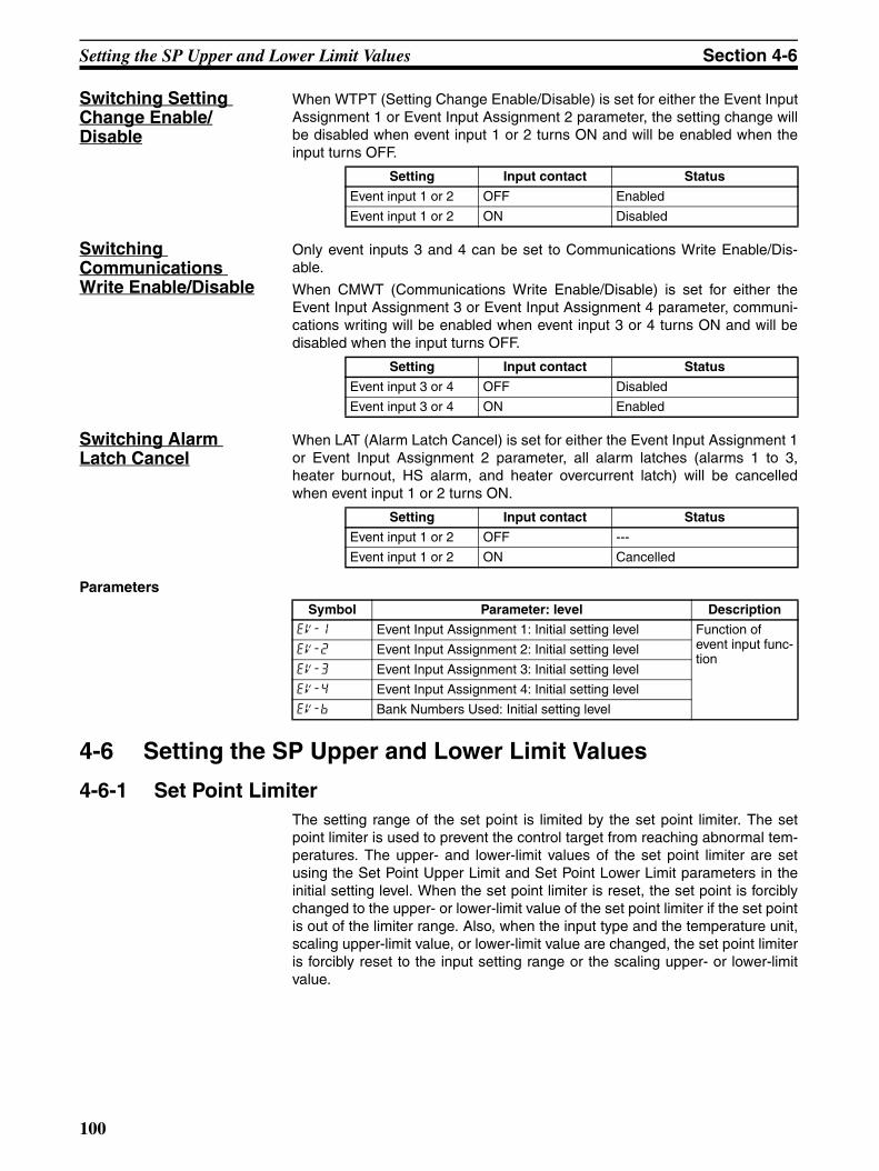
Setting the SP Upper and Lower Limit Values Section 4-6
Switching Setting Change Enable/Disable
When WTPT (Setting Change Enable/Disable) is set for either the Event InputAssignment 1 or Event Input Assignment 2 parameter, the setting change willbe disabled when event input 1 or 2 turns ON and will be enabled when theinput turns OFF.
Switching Communications Write Enable/Disable
Only event inputs 3 and 4 can be set to Communications Write Enable/Dis-able.
When CMWT (Communications Write Enable/Disable) is set for either theEvent Input Assignment 3 or Event Input Assignment 4 parameter, communi-cations writing will be enabled when event input 3 or 4 turns ON and will bedisabled when the input turns OFF.
Switching Alarm Latch Cancel
When LAT (Alarm Latch Cancel) is set for either the Event Input Assignment 1or Event Input Assignment 2 parameter, all alarm latches (alarms 1 to 3,heater burnout, HS alarm, and heater overcurrent latch) will be cancelledwhen event input 1 or 2 turns ON.
Parameters
4-6 Setting the SP Upper and Lower Limit Values
4-6-1 Set Point LimiterThe setting range of the set point is limited by the set point limiter. The setpoint limiter is used to prevent the control target from reaching abnormal tem-peratures. The upper- and lower-limit values of the set point limiter are setusing the Set Point Upper Limit and Set Point Lower Limit parameters in theinitial setting level. When the set point limiter is reset, the set point is forciblychanged to the upper- or lower-limit value of the set point limiter if the set pointis out of the limiter range. Also, when the input type and the temperature unit,scaling upper-limit value, or lower-limit value are changed, the set point limiteris forcibly reset to the input setting range or the scaling upper- or lower-limitvalue.
Setting Input contact Status
Event input 1 or 2 OFF Enabled
Event input 1 or 2 ON Disabled
Setting Input contact Status
Event input 3 or 4 OFF Disabled
Event input 3 or 4 ON Enabled
Setting Input contact Status
Event input 1 or 2 OFF ---
Event input 1 or 2 ON Cancelled
Symbol Parameter: level Description
ev-1 Event Input Assignment 1: Initial setting level Function of event input func-tion
ev-2 Event Input Assignment 2: Initial setting level
ev-3 Event Input Assignment 3: Initial setting level
ev-4 Event Input Assignment 4: Initial setting level
ev-b Bank Numbers Used: Initial setting level
100

Setting the SP Upper and Lower Limit Values Section 4-6
Parameters
4-6-2 SettingSet the set point upper and lower limits in the Set Point Upper Limit and SetPoint Lower Limit parameters in the initial setting level. In this example, it isassumed that the input type is set to a K thermocouple with a temperaturerange of −200.0 to 1300.0°C.
Setting the Set Point Upper-limit Value
Operating Procedure Set Point Upper Limit = 1000
A
C
B
B
Input setting range
Set point limiter
Setting range
Upper limit value changed
Input type changed
Upper limit value changed
Set point
(Cannot be set.)
Set point
Set point
(Can be set.) Set value Upper/lower limit valuesSensor upper/lower limit values
Symbol Parameter: level Description
sl-h
sl-l
Set Point Upper Limit: Initial setting levelSet Point Lower Limit: Initial setting level
To limit the SP settingTo limit the SP setting
−200.0 1300.0
−100.0 1000.0
Input setting range
Set point limiter
1. Press the O Key for at least three seconds to move from the operationlevel to the initial setting level.
2. Select the Set Point Upper Limit parameter.
3. Use the U and D Keys to set the parameter to 1000.0.
in-t5
Input Type
C
sl-h1300.0
Set Point Upper-limit
C
sl-h1000.0
101

Using the SP Ramp Function to Limit the SP Change Rate Section 4-7
Setting the Set Point Lower-limit Value
Operating Procedure Set Point Lower Limit = −100
4-7 Using the SP Ramp Function to Limit the SP Change Rate
4-7-1 SP RampThe SP ramp function is used to restrict the width of changes in the set pointas a rate of change. When the SP ramp function is enabled and the changewidth exceeds the specified rate of change, an area where the set point isrestricted will be created, as shown in the following diagram.
During the SP ramp, control will be performed not for the specified set pointbut rather for the set point restricted by the rate of change set for the SP rampfunction.
The rate of change during SP ramp is specified using the SP Ramp Set Valueand SP Ramp Time Unit parameters. The SP Ramp Set Value parameter isset to OFF by default, i.e., the SP ramp function is disabled.
The SP Ramp Set Value parameter can be set for each bank. Select the banknumber in the Display Bank Selection parameter (bank setting level), and thenset the SP Ramp Set Value parameter. Also, the ramp set point for the currentbank can be monitored in the Set Point During SP Ramp parameter (opera-tion level). Use this parameter when monitoring SP ramp operation.
If the SP Ramp Set Value parameter setting is changed in the adjustmentlevel, the change will be reflected in the SP Ramp Set Value parameter for thecurrent bank.
The SP ramp function is enabled even when switching from local SP toremote SP, and the SP ramp will operate.
1. Select the Set Point Lower Limit parameter in the initial setting level.
2. Use the U and D Keys to set the parameter to −100.0.
C
sl-l-200.0
Set Point Lower Limit
C
sl-l-100.0
SP
SP rampSP after change
SP before change
Point of change
Time
SP ramp set value
SP ramp time unit (s/min)
102

Using the SP Ramp Function to Limit the SP Change Rate Section 4-7
Parameters
Operation at Startup If the SP ramp function is enabled when the Controller is turned ON or whenswitching from STOP to RUN mode, the process value reaches the set pointusing the SP ramp function in the same way as when the set point is changed.In this case, operation is carried out with the process value treated as the setpoint before the change was made. The direction of the SP ramp changesaccording to the relationship between the process value and the set point.
Restrictions during SP Ramp Operation
• Execution of auto-tuning starts after the end of the SP ramp.
• When control is stopped or an error occurs, the SP ramp function is dis-abled.
Symbol Parameter: level Description
∗olh (∗: 1 to 8)∗oll (∗: 1 to 8)sl-h
sl-l
∗spr (∗: 0 to 7)spru
alsp
PID* MV Upper Limit: PID setting levelPID* MV Lower Limit: PID setting levelSet Point Upper Limit: Initial setting levelSet Point Lower Limit: Initial setting levelBank* SP Ramp Set Value: Bank setting levelSP Ramp Time Unit: Advanced function setting levelAlarm SP Selection: Advanced function setting level
To limit the manipulated variableTo limit the manipulated variableTo limit the SP settingTo limit the SP settingTo limit the SP rate of changeUnit for setting the SPAlarm SP selection
SP SP
PV
PV
PV < SP
SP rampSet point
Time Time
Power ON Power ON
PV > SP
SP ramp
Same rate of change
Set point
103

Moving to the Advanced Function Setting Level Section 4-8
Alarms during SP Ramp Operation
The operation of alarms during SP ramp operation depends on whetheralarms are set to be based on the ramp set point or the target set point (referto the following diagrams). The set point to be used is set in the Alarm SPSelection parameter.
4-8 Moving to the Advanced Function Setting LevelUse the following procedure to move to the advanced function setting level.
1,2,3... 1. Press the O and M Keys simultaneously for at least three seconds in op-eration level.
Note The key pressing time can be changed in the Move to Protect LevelTime parameter (advanced function setting level).
Alarm SP Selection = Ramp SP (Alarm Type: 1 (Upper/Lower Limits))
Alarm SP Selection = Target SP (Alarm Type: 1 (Upper/Lower Limits))
Temperature
Temperature
Time
Time
Alarm output ON
Alarm output ON
Alarm output ON
Alarm output ON
Protect Level 2. The Controller moves to the protect level, and the Operation/AdjustmentProtect parameter is displayed.
3. Press the M Key once to move to the Initial Setting/Communications Pro-tect parameter.
4. Set the set value to 0. The default setting is 0 (possible to reach).
oapt0
Operation/Adjust-ment Protect
icpt0
Initial Setting/ Communica-tions Protect
icpt0
104

Moving to the Advanced Function Setting Level Section 4-8
Operation Level 5. Press the O and M Keys simultaneously for at least one second to re-turn to the operation level.
Initial Setting Level 6. Move to the advanced function setting level.Press the O Key for at least three seconds to move from the operationlevel to the initial setting level.
Initial Setting Level 7. Select the Move to Advanced Function Setting Level parameter by press-ing the M Key.
Advanced function setting level 8. Press the D Key, enter the password (−169), and then either press theM Key or leave the setting for at least two seconds to move to the ad-vanced function setting level from the initial setting level.
Initial Setting Level 9. To return to the initial setting level, press the O Key for at least one sec-ond.
Operation Level 10. To return to the operation level, press the O Key for at least one second.
C
25.0100.0
PV/SP
in-t5
Input Type
amov-169
Move to Ad-vanced Function Setting Level
initoff
Parameter Initialization
in-t5
Input Type
C
25.0100.0
PV/SP
105

Using the Key Protect Level Section 4-9
4-9 Using the Key Protect Level
4-9-1 Protection• To move to the protect level, press the O and M Keys simultaneously for
at least three seconds in operation level or adjustment level. (See note.)
Note The key pressing time can be changed in the Move to Protect LevelTime parameter (advanced function setting level).
• The protect level protects parameters that are not changed during Con-troller operation until operation is started to prevent them from being mod-ified unintentionally. There are four types of protection: operation/adjustment protect, initialsetting/communications protect, setting change protect, and PF Key pro-tect.
• The protect level settings restrict the range of parameters that can beused.
Operation/Adjustment Protect
The following table shows the relationship between set values and the rangeof protection.
• Parameters are not protected when the set value is set to 0.
• The default is 0.
Initial Setting/Communications Protect
This protect level restricts movement to the initial setting level, communica-tions setting level, and advanced function setting level.
• The default is 0.
Setting Change Protect
This protect level restricts key operations.
oapt0
Level Set value
0 1 2 3
Operation level
PV Can be dis-played
Can be dis-played
Can be dis-played
Can be dis-played
PV/SP Can be dis-played and changed
Can be dis-played and changed
Can be dis-played and changed
Can be dis-played
Others Can be dis-played and changed
Can be dis-played and changed
Cannot be displayed and moving to other levels is not possible
Cannot be displayed and moving to other levels is not possible
Adjustment level Can be dis-played and changed
Cannot be displayed and moving to other levels is not possible
Cannot be displayed and moving to other levels is not possible
Cannot be displayed and moving to other levels is not possible
icpt0
Set value
Initial setting level Communications setting level
Advanced function setting level
0 Possible to reach Possible to reach Possible to reach
1 Possible to reach Possible to reach Not possible to reach
2 Not possible to reach Not possible to reach Not possible to reach
wtptoff
Set value Description
OFF Settings can be changed using key operations.
ON Settings cannot be changed using key operations. (The protect level settings, however, can be changed.)
106

Using the Key Protect Level Section 4-9
• The default is OFF.
• The all protect indication ( ) will light when setting change protect isset.
PF Key Protect This protect level enables or disables PF Key operations.
• The default is OFF.
4-9-2 Entering the Password to Move to the Protect Level• Protect level can be moved to only by display the password display and
entering the correct password. (The user can set any password in theProtect Level Password parameter. If no password is set (i.e., if the pass-word is set to 0 in the Protect Level Password parameter), the passwordinput display to move to protect level will not be displayed and the protectlevel can be moved to directly.
Operating Procedure Use the following procedure to move to protect level.
Example with a Password of 1234
Example with No Password Set
pfptoff
Set value Description
OFF PF Key enabled.
ON PF Key disabled (Operation as function key prohibited).
Operation Level
Protect Level 1. Press the O and M Keys simultaneously for at least the time set in theMove to Protect Level Time parameter to move from the operation levelto the protect level.
2. Press the U Key to set the parameter to 1234 (password input).
Protect Level 3. Move to the Operation/Adjustment Protect parameter by pressing the Oor M Key or leaving the setting for at least two seconds.
Operation Level
Protect Level Press the O and M Keys simultaneously for at least the time set in theOperation/Adjustment Protect parameter to move from the operation level tothe protect level.When a password is not set, the Operation/Adjustment Protect parameterwill be displayed.
C
25.0100.0
PV/SP
pmov0
Move to Protect Level
pmov1234
oapt0
Operation/Adjust-ment Protect
C
25.0100.0
PV/SP
oapt0
Operation/Adjust-ment Protect
107

Using the Key Protect Level Section 4-9
Setting the Password
Operating Procedure Use the following procedure to set the password to move to the protect level.
Example To set the Password to 1234
Communications Operation Command to Move to the Protect Level
• The Write Variable operation command can be used via communicationsto write the password to the Move to Protect Level parameter. When thecorrect password is written, the display will change to the Operation/Adjustment Protect parameter and writing the parameters in the protectlevel will be enabled.
Note (1) If the Write Variable operation command is used to write the wrong pass-word to the Move to Protect Level parameter after the correct parameterhas been written, the Move to Protect Level parameter will be displayedand any Write Variable operation commands to write parameters in theprotect level will result in operation errors.
(2) If a password is not set or if it is set to 0, the display will change to theOperation/Adjustment Protect parameter and writing the parameters inthe protect level will be enabled immediately.
Operation Level
Protect Level 1. Press the O and M Keys simultaneously for at least the time set in theMove to Protect Level Time parameter to move from the operation levelto the protect level.
Protect Level 2. Select the Password to Move to Protect Level parameter by pressing theM Key.
3. Press the O and U Keys to set the parameter to 1234.(To prevent setting the password incorrectly, the U and O Keys or Dand O Keys must be pressed simultaneously to set the password.)
Note Protection cannot be cleared or changed without the password. Becareful not to forget it. If you forget the password, contact yourOMRON sales representative.
C
25.0100.0
PV/SP
oapt0
Operation/Adjust-ment Protect
prlp0
Password to Move to Protect Level
prlp1234
108

PV Change Color Section 4-10
4-10 PV Change Color
4-10-1 PV Color Change FunctionUse the PV color change function to change the color of the PV display (No. 1display).
There are three display colors, orange, red, and green, and you can selectfrom the following three modes and eight functions.
• Constant: This mode displays orange, red, or green all the time.
• Linked to Alarm 1: This mode switches the PV display color from red togreen when alarm 1 turns ON or from green to red when alarm 1 turnsON.
• Linked to PV stable band: This mode switches the PV display colorbetween red outside the PV stable band and green within PV stable band,or between green outside the PV stable band and red within PV stableband.Set the PV stable band in the PV Stable Band parameter (advanced func-tion setting level).
• The default is red (red).
The following tables shows the display functions that can be set using the PVcolor change function.
colrPV Change Color
Mode Setting Function PV change color Application example
Constant org Orange Constant: Orange To match the display color with other Controller models
red Red Constant: Red To match the display color with other Controller models
grn Green Constant: Green To match the display color with other Controller models
Linked to alarm 1
ALM1 not lit ALM1 lit Application example
r-g Red to Green Red Green To display the PV reached sig-nal
g-r Green to Red Green Red To display error signals
Linked to PV stable band
Low Within PV stable band
High Application example
r-g.r Red to Green to Red
Red Green Red To display stable status
g-o.r Green to Orange to Red
Green Orange Red To display stable status
o-g.r Orange to Green to Red
Orange Green Red To display stable status
PV
SP
Alarm value
ALM1 lit
PV
SP
PV stable band
PV stable band
Low Within High
109

PV Change Color Section 4-10
PV Stable Band When the mode to link to the PV stable band is selected, the PV display colorwill change according to whether the present value (PV) is lower than, within,or higher than the PV stable band shown in the following figure. The PV stableband is set with the SP as the center, as shown below.
The default is 5.0 (°C/°F) for a temperature input and 5.0% FS for an analoginput.
4-10-2 Setting
Setting the PV Change Color to Indicate Stable Status
To display the PV in a stable green display when the PV is within ±15.0°C ofthe set point to enable checking the control process at a glance, set the PVChange Color and PV Stable Band parameters.
PV change color = r-gr (Red to Green to Red)
PV stable band = 15.0°C
Operating Procedure Release the protection before setting the PV Change Color and PV StableBand parameters to enable moving to advanced function setting level. (Referto steps 1 to 8 on page 104.)
PV Change Color: r-g.r (Red to Green to Red)
PV Stable Band: 15.0 (°C)
pv-bPV Stable Band
PV
SP
PV stable band
PV stable band
Low Within High
Operation Level
Initial Setting Level 1. Press the O Key for at least three seconds to move from the operationlevel to the initial setting level.
Initial Setting Level 2. Select the Move to Advanced Function Setting Level parameter by press-ing the M Key.
3. Use the D Key to enter “−169” (the password).
Advanced Function Setting Level Move to the advanced function setting level by pressing the M Key orleaving the setting for at least two seconds.
Advanced Function Setting Level 4. Select the PV Change Color parameter by pressing the M Key.
C
25.0100.0
PV/SP
in-t5
Input Type
amov-169
Move to Ad-vanced Function Setting Level
initoff
Parameter Initialization
colrred
PV Change Color
110

PV Change Color Section 4-10
5. Press the U Key to set the parameter to r-gr.
Advanced Function Setting Level 6. Select the PV Stable Band parameter by pressing the M Key.
7. Use the U Key to set the parameter to 15.0.
8. To return to the initial setting level, press the O Key for at least one sec-ond.
Operation Level 9. To return to the operation level, press the O Key for at least one second.
colrr-g.r
C
pv-b5.0
PV Stable Band
C
pv-b15.0
C
25.0100.0
PV/SP
111

Alarm Delays Section 4-11
4-11 Alarm Delays
4-11-1 Alarm Delays• Delays can be set for the alarm outputs. ON and OFF delays can be set
separately for alarms 1, 2, and 3. The ON and OFF delays for alarm 1function only for the alarm function. If the alarm 1 function is set to be out-put as an OR with other alarms (i.e., the heater burnout alarm, HS alarm,heater overcurrent alarm, or input error output alarm), delays cannot beset for the other alarms. The ON and OFF delays for alarms 1, 2, and 3also apply to the individual SUB1, SUB2, and SUB3 indicators and tocommunications status. The alarm ON delays will also function whenpower is turned ON or when moving from the initial setting level to opera-tion level (e.g., to software resets). All outputs will turn OFF and the OFFdelays will not function when moving to the initial setting level or when analarm is output for a A/D converter error.
Operation of Alarm ON and OFF Delays (for an Upper-limit Alarm)
• The alarm will not turn ON if the time that the alarm is ON is equal to orless than the ON delay set time. Also, the alarm will not turn OFF if thetime that the alarm is OFF is equal to or less than the OFF delay set time.
• If an alarm turns OFF and then back ON during the ON delay time, thetime will be remeasured from the last time the alarm turns ON. Also, if analarm turns ON and then back OFF during the OFF delay time, the timewill be remeasured from the last time the alarm turns OFF.
Parameters Related to Alarm Delays
PV
Alarm settingAlarm hysteresis
Alarm status
ON delay set time
ON delay set time
OFF delay set time
Alarm Latch = OFF
Alarm will not turn ON.
Parameter name Symbol Set (monitor) values
Alarm 1 ON Delay a1on 0 to 999 (s)
Alarm 2 ON Delay a2on 0 to 999 (s)
Alarm 3 ON Delay a3on 0 to 999 (s)
Alarm 1 OFF Delay a1of 0 to 999 (s)
Alarm 2 OFF Delay a2of 0 to 999 (s)
Alarm 3 OFF Delay a3of 0 to 999 (s)
112

Alarm Delays Section 4-11
Note (1) The defaults are 0, i.e., the ON and OFF delays are disabled.
(2) The parameters are displayed when alarm functions are assigned andwhen the alarm type is set to any type but 0 (none), 12: LBA, or 13: PVchange rate alarm.
Operating Procedure Use the following procedure to set ON and OFF delays for the alarm 1.
An ON delay of 5 seconds and an OFF delay of 10 s will be set.
Operation Level
Initial Setting Level 1. Press the O Key for at least three seconds to move from the operationlevel to the initial setting level.
Initial Setting Level 2. Select the Move to Advanced Function Setting Level parameter by press-ing the M Key. (For details on moving between levels, refer to 4-8 Movingto the Advanced Function Setting Level.)
Advanced Function Setting Level 3. Press the D Key to enter the password (−169) and move from the initialsetting level to the advanced function setting level.
Advanced Function Setting Level 4. Press the M Key to select the Alarm 1 ON Delay parameter.
5. Press the U Key to set the parameter to 5.
Advanced Function Setting Level 6. Press the M Key to select the Alarm 1 OFF Delay parameter.
7. Press the U Key to set the parameter to 10.
Initial Setting Level 8. Press the O Key for at least one second to move from the advancedfunction setting level to the initial setting level.
C
25.0100.0
PV/SP
in-t5
Input Type
amov0
Move to Ad-vanced Function Setting Level
initoff
Parameter Initialization
a1on0
Alarm 1 ON Delay
a1on5
a1of0
Alarm 1 OFF Delay
a1of10
in-t5
Input Type
113

Loop Burnout Alarm Section 4-12
4-12 Loop Burnout Alarm
4-12-1 Loop Burnout Alarm (LBA)• The loop burnout alarm can be used only with standard models.
• With a loop burnout alarm, there is assumed to be an error in the controlloop if the control deviation (SP − PV) is greater than the threshold set inthe LBA Level parameter and if the control deviation is not reduced by atleast the value set in the LBA Detection Band parameter within the LBAdetection time.
• Loop burnout alarms are detected at the following times.
If the control deviation is reduced in the area between 1 and 2 (i.e., the setpoint is approached) and the amount the control deviation is reduced is atleast equal to the LBA band, the loop burnout alarm will remain OFF.
The process value is within the LBA level between 3 and 4, and thus loopburnout alarms will not be detected. (The loop burnout alarm will remain OFF.)
If the process value is outside the LBA level between 4 and 5 and the controldeviation is not reduced by at least the LBA band within the LBA detectiontime, the loop burnout alarm will turn ON.
If the control deviation is reduced in the area between 5 and 6 (i.e., the setpoint is approached) and the amount the control deviation is reduced is atleast equal to the LBA band, the loop burnout alarm will turn OFF.
If the control deviation is reduced in the area between 6 and 7 (i.e., the setpoint is approached) and the amount the control deviation is reduced is lessthan the LBA band, the loop burnout alarm will turn ON.
• If the LBA detection time, LBA level, LBA detection band, and PID set-tings are not appropriate, alarms may be detected inappropriately oralarms may not be output when necessary.
• Loop burnout alarms may be detected if unexpectedly large disturbancesoccur continuously and a large deviation does not decrease.
Operation Level 9. Press the O Key for at least one second to move from the initial settinglevel to the operation level.
C
25.0100.0
PV/SP
LBA ONLBA ON LBA OFFLBA OFF(1)(2) (3) (4) (5) (6) (7)
Set point
LBA detec-tion time
Area where LBA is not detected
LBA detection time LBA detection
time
LBA detection time
LBA band LBA band
LBA band
LBA level
LBA level
114

Loop Burnout Alarm Section 4-12
• If a loop burnout occurs when the set point is near the ambient tempera-ture, the temperature deviation in a steady state may be less than the LBAlevel, preventing detection of the loop burnout.
• If the set point is so high or low that it cannot be reached even with a sat-urated manipulated variable, a temperature deviation may remain even ina steady state and a loop burnout may be detected.
• Detection is not possible if a fault occurs that causes an increase in tem-perature while control is being applied to increase the temperature (e.g.,an SSR short-circuit fault).
• Detection is not possible if a fault occurs that causes a decrease in tem-perature while control is being applied to decrease the temperature (e.g.,a heater burnout fault).
Parameters Related to Loop Burnout Alarms
Note Set “None” as the unit for analog inputs.
• A loop burnout alarm can be output by setting the alarm 1 type to 12(LBA).
• A setting of 12 (LBA) can be set for alarm 2 or alarm 3, but the setting willbe disabled.
• Loop burnouts are not detected during SP ramp operation.
• Loop burnouts are not detected during auto-tuning, manual operation, orwhile stopped.
• If the alarm 1 latch is set to ON, the latch will be effective for the loopburnout alarm.
• Loop burnout alarms are not detected when using a remote SP.
Automatically Setting the LBA Detection Time
• Automatic setting is not possible for ON/OFF control. Set the LBA Detec-tion Time parameter in the advanced function setting level.
• When PID control is being used, the LBA detection time can be set indi-vidually for each PID set. First select the PID set number in the DisplayPID Selection parameter (PID setting level), and then set the time in theLBA Detection Time parameter.
• The LBA detection time is automatically set by auto-tuning, and the exe-cution results are saved in the PID set when auto-tuning is started. (Theresults are not set automatically, however, for heating/cooling control.)
• If the optimum LBA detection time is not obtained by auto-tuning, set theLBA Detection Time parameter (PID setting level).
Parameter name Symbol Setting range Remarks
PID* LBA Detection Time(*: 1 to 8)
∗.lba 0 to 9999 (s) Setting 0 disables the LBA function.
LBA Detection Time lba
LBA Level lbal Controllers with tempera-ture inputs
0.1 to 3,240.0 (°C/°F) (See note.)
Default: 8.0 (°C/°F)
Controllers with analog inputs
0.01 to 99.99 (%FS) Default: 10.00% FS
LBA Band lbab Controllers with tempera-ture inputs
0.0 to 3,240.0 (°C/°F) (See note.)
Default: 3.0 (°C/°F)
Controllers with analog inputs
0.00 to 99.99 (%FS) Default: 0.20% FS
115

Loop Burnout Alarm Section 4-12
Determining the LBA Detection Time
• To manually set the LBA detection time, set the LBA Detection Timeparameter to twice the LBA reference time given below.
1,2,3... 1. Set the output to the maximum value.
2. Measure the time required for the width of change in the input to reach theLBA band.
3. Set the LBA Detection Time parameter to two times the measured time.
LBA Level • Set the control deviation when the control loop is working properly.
• The default is 8.0 (°C/°F) for a temperature input and 10.00% FS for ananalog input.
LBA Band • There is assumed to be an error in the control loop if the control deviationis greater than the threshold set in the LBA Level parameter and if thecontrol deviation does not change by at least the value set in the LBABand parameter.
• The default is 3.0 (°C/°F) for a temperature input and 0.20% FS for ananalog input.
Operating Procedure Perform the following procedure to use the loop burnout alarm.
In this example, the LBA detection time is set to 10, the LBA level is set to 8.0,and the LBA band is set to 3.0.
MV = 100%
PVTemperature
Time
Measurement time Tm
LBA band
LBA detection time = Tm × 2
Operation Level
Initial Setting Level 1. Press the O Key for at least three seconds to move from the operationlevel to the initial setting level.
Initial Setting Level 2. Select the Alarm 1 Type parameter by pressing the M Key.
C
25.0100.0
PV/SP
in-t5
Input Type
alt12
Alarm 1 Type
116

Loop Burnout Alarm Section 4-12
Initial Setting Level 3. Press the U Key to set the parameter to 12.To return to the operation level, press the O Key for at least one second.
Operation Level 4. Press the O Key to move from the operation level to the PID setting level.
PID Setting Level 5. The current PID set number will be displayed. Press the U or D Key toselect PID set 2.
6. Press the M Key to select the PID 2 LBA Detection Time parameter.
7. Press the U Key to set the parameter to 10.
Initial Setting Level 8. Press the O Key for at least three seconds to move to the initial settinglevel.
9. Select the Move to Advanced Function Setting Level parameter by press-ing the M Key. (For details on moving between levels, refer to 4-8 Movingto the Advanced Function Setting Level.)
Advanced Function Setting Level 10. Press the D Key to enter the password (−169), and move from the initialsetting level to the advanced function setting level.
Advanced Function Setting Level 11. Select the LBA Level parameter by pressing the M Key.
12. Press the U Key to set the parameter to 8.0. (The default is 8.0.)
Advanced Function Setting Level 13. Select the LBA Band parameter by pressing the M Key.
14. Press the U or D Key to set the parameter to 3.0. (The default is 3.0.)
alt112
C
25.0100.0
PV/SP
d.pid2
Display PID Selection
2.lba0
PID 2 LBA Detection Time
2.lba10
in-t5
Input Type
amov0
Move to Ad-vanced Function Setting Level
initoff
Parameter Initialization
C
lbal8.0
LBA Level
C
lbal8.0
C
lbab3.0
LBA Band
C
lbab3.0
117

Loop Burnout Alarm Section 4-12
Initial Setting Level 3. Press the U Key to set the parameter to 12.To return to the operation level, press the O Key for at least one second.
Operation Level 4. Press the O Key to move from the operation level to the PID setting level.
PID Setting Level 5. The current PID set number will be displayed. Press the U or D Key toselect PID set 2.
6. Press the M Key to select the PID 2 LBA Detection Time parameter.
7. Press the U Key to set the parameter to 10.
Initial Setting Level 8. Press the O Key for at least three seconds to move to the initial settinglevel.
9. Select the Move to Advanced Function Setting Level parameter by press-ing the M Key. (For details on moving between levels, refer to 4-8 Movingto the Advanced Function Setting Level.)
Advanced Function Setting Level 10. Press the D Key to enter the password (−169), and move from the initialsetting level to the advanced function setting level.
Advanced Function Setting Level 11. Select the LBA Level parameter by pressing the M Key.
12. Press the U Key to set the parameter to 8.0. (The default is 8.0.)
Advanced Function Setting Level 13. Select the LBA Band parameter by pressing the M Key.
14. Press the U or D Key to set the parameter to 3.0. (The default is 3.0.)
alt112
C
25.0100.0
PV/SP
d.pid2
Display PID Selection
2.lba0
PID 2 LBA Detection Time
2.lba10
in-t5
Input Type
amov0
Move to Ad-vanced Function Setting Level
initoff
Parameter Initialization
C
lbal8.0
LBA Level
C
lbal8.0
C
lbab3.0
LBA Band
C
lbab3.0
118

Performing Manual Control Section 4-13
4-13 Performing Manual Control
4-13-1 Manual Operation• With standard models, the MV is manipulated directly. With position-pro-
portional models, the MV is manipulated through the amount of valveopening or by parameter settings.
• The manipulated variable can be set in manual mode if the PV/MV param-eter is displayed in the manual control level. The final MV used in auto-matic mode will be used as the initial manual MV when moving fromautomatic mode to manual mode. In manual mode, the change value willbe saved immediately and reflected in the actual MV.
• Manual operation can be used only for PID control.
Standard Models • The automatic display return function will not operate in manual mode.
• Balanceless-bumpless operation will be performed for the MV whenswitching from manual operation to automatic operation. (See note.)
• If a power interruption occurs during manual operation, manual operationwill be restarted when power is restored using the same MV as whenpower was interrupted.
• Switching between automatic and manual operation is possible for a max-imum of one million times.
The overall manual operation is illustrated in the following figure.
Position-proportional Models
• When floating control is used or when the Direct Setting of Position Pro-portional MV parameter is set to OFF:
• Pressing the U Key turns ON the open output, and pressing the DKey turns ON the close output.
Initial Setting Level 15. Press the O Key for at least one second to move from the advancedfunction setting level to the initial setting level.
Operation Level 16. Press the O Key for at least one second to move from the initial settinglevel to the operation level.
in-t5
Input Type
C
25.0100.0
PV/SP
0ONOFF
MV (%)
Time
Balanceless-bumpless
Manual
Automatic
MV switched
Power in-terrupted
119

Performing Manual Control Section 4-13
• The automatic display return function will not operate in manual mode.
• Balanceless-bumpless operation will be performed for the MV whenswitching between manual and automatic operation. (See note.)
• Switching between manual and automatic operation is possible for amaximum of one million times.
• When close control is used or when the Direct Setting of Position Propor-tional MV parameter is set to ON:
• Just as with standard models, the MV is set numerically.
• The automatic display return function will not operate in manual mode.
• Balanceless-bumpless operation will be performed for the MV whenswitching between manual and automatic operation. (See note.)
Note In balanceless-bumpless operation, the MV before switching isused initially after the switch and then gradually changed to achievethe proper value after switch to prevent radical changes in the MVafter switching operation.
• If a power interruption occurs during manual operation, manual operationwill be restarted when power is restored using the same MV as whenpower was interrupted.
• Switching between manual and automatic operation is possible for a max-imum of one million times.
• Operation will be as described below if a potentiometer input error occurs.
When the Manual MV Limit Enable Parameter Is Set to OFF:
If the manual MV is other than the above, the open and close outputswill both be OFF.
When the Manual MV Limit Enable Parameter Is Set to ON:
If the manual MV is other than the above, the open and close outputswill both be OFF.
Related Displays and Parameters
Note (1) Refer to 4-17 Output Adjustment Functions for information on the priorityfor the MV.
Manual MV ≥ 100Manual MV ≤ 0
Open output: ONClose output: ON
Manual MV = MV upper limit
Manual MV = MV lower limit
Open output: ON
Close output: ON
Parameter name Symbol Level Remarks
PV/MV (Manual MV) --- Manual Control Level Changes the manual MV.Standard: −5.0 to 105.0 (See note 2.)Heating/cooling: −105.0 to 105.0 (See note 2.)Position-proportional: −5.0 to 105.0 (See notes 2 and 3.)
Direct Setting of Position Proportional MV
pmvd Advanced Function Setting Level
Selects the method for specifying each MV for manual operation, when stopping, or when an error occurs.OFF: All open, hold, all closedON: −5.0 to 105%
Auto/Manual Switch a-m Operation Level Switches between automatic and manual modes.
Auto/Manual Select Addi-tion
amad Advanced Function Setting Level
Enables switching between automatic and man-ual modes.
120

Performing Manual Control Section 4-13
(2) For Manual MV Limit Enable, this value will be between the MV upper limitand the MV lower limit.
(3) This setting is enabled only when the Direct Setting of Position Propor-tional MV parameter is set to ON.
Manual MV Limit Enable
When the Manual MV Limit Enable parameter is set to ON (enabled), the MVlimits will function and the setting range for the Manual MV parameter will bebetween the MV upper limit and the MV lower limit. When the parameter is setto OFF (disabled), MV limits will not function.
Moving from the Operation Level to the Manual Control Level
• When the O Key is pressed for at least 3 seconds in the operation level'sauto/manual switching display, the manual mode will be entered and themanual control level will be displayed. It is not possible to move to any dis-plays except for the PV/MV parameter during manual operation. Press theO Key for at least one second from the PV/MV parameter display in man-ual control level to return to automatic mode and display the top parame-ter in the operation level.
• If an event input is set to MANU (auto/manual), the Auto/Manual Switchparameter will not be displayed. Use the event input to switch betweenautomatic and manual modes.
Parameter name Setting range Default
Manual MV Limit Enable
OFF: Disabled, ON: Enabled ON
C
M
M
M
C
C
M
a-m
25.0
25.0100.0
25.020.0
Press O key for at least 1 s.
a-m
bank0
Operation Level
Manual Control Level
PV/MVPress O key for at least 3 s.
a-m display flashes for at least 1 s.
PV
PV/SP
Auto/Manual Switch
Bank No.
121
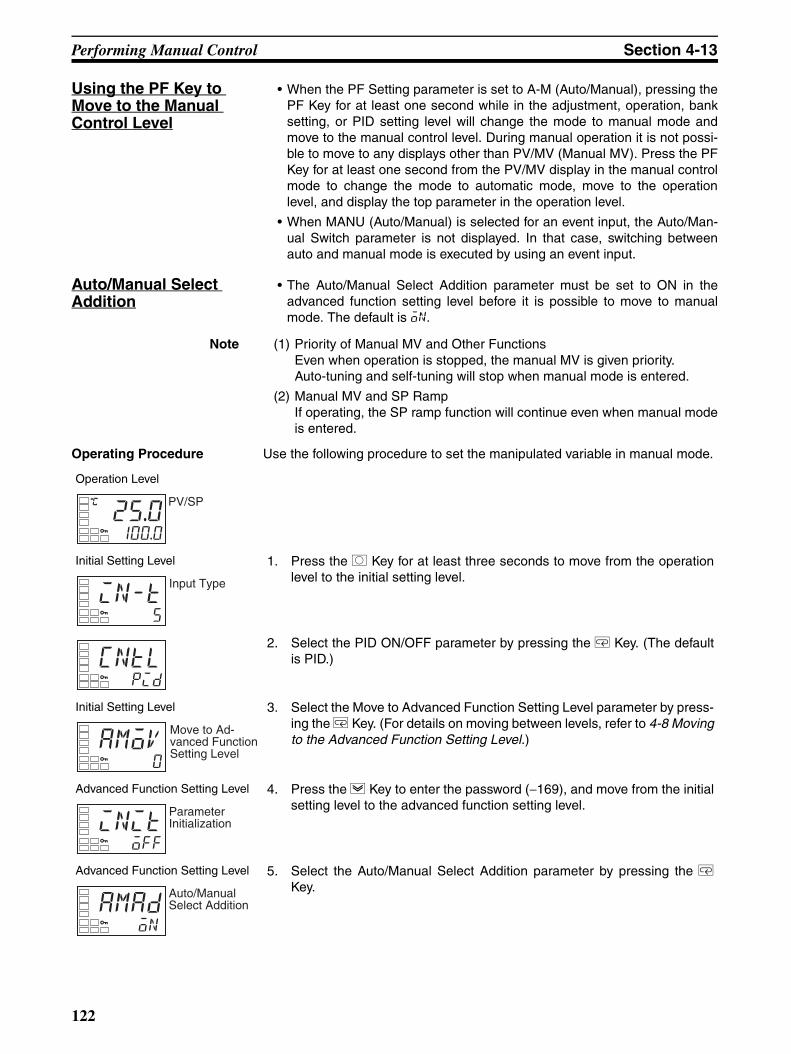
Performing Manual Control Section 4-13
Using the PF Key to Move to the Manual Control Level
• When the PF Setting parameter is set to A-M (Auto/Manual), pressing thePF Key for at least one second while in the adjustment, operation, banksetting, or PID setting level will change the mode to manual mode andmove to the manual control level. During manual operation it is not possi-ble to move to any displays other than PV/MV (Manual MV). Press the PFKey for at least one second from the PV/MV display in the manual controlmode to change the mode to automatic mode, move to the operationlevel, and display the top parameter in the operation level.
• When MANU (Auto/Manual) is selected for an event input, the Auto/Man-ual Switch parameter is not displayed. In that case, switching betweenauto and manual mode is executed by using an event input.
Auto/Manual Select Addition
• The Auto/Manual Select Addition parameter must be set to ON in theadvanced function setting level before it is possible to move to manualmode. The default is on.
Note (1) Priority of Manual MV and Other FunctionsEven when operation is stopped, the manual MV is given priority. Auto-tuning and self-tuning will stop when manual mode is entered.
(2) Manual MV and SP RampIf operating, the SP ramp function will continue even when manual modeis entered.
Operating Procedure Use the following procedure to set the manipulated variable in manual mode.
Operation Level
Initial Setting Level 1. Press the O Key for at least three seconds to move from the operationlevel to the initial setting level.
2. Select the PID ON/OFF parameter by pressing the M Key. (The defaultis PID.)
Initial Setting Level 3. Select the Move to Advanced Function Setting Level parameter by press-ing the M Key. (For details on moving between levels, refer to 4-8 Movingto the Advanced Function Setting Level.)
Advanced Function Setting Level 4. Press the D Key to enter the password (−169), and move from the initialsetting level to the advanced function setting level.
Advanced Function Setting Level 5. Select the Auto/Manual Select Addition parameter by pressing the MKey.
C
25.0100.0
PV/SP
in-t5
Input Type
cntlpid
amov0
Move to Ad-vanced Function Setting Level
initoff
Parameter Initialization
amadon
Auto/Manual Select Addition
122

Performing Manual Control Section 4-13
Operating Procedure In this example, A-M (Auto/Manual) is set for the PF Setting parameter(E5AN/EN-H only).
6. Use the U Key to set the parameter to ON. (The default is ON.)
Initial Setting Level 7. Press the O Key for at least one second to move from the advancedfunction setting level to the initial setting level.
8. Press the O Key for at least one second to move from the initial settinglevel to the operation level.
Operation Level 9. Select the Auto/Manual Switch parameter by pressing the M Key.
Manual Control Level 10. Press the O Key for at least three seconds to move from the operationlevel to the manual control level.
11. Press the U or D Key to set the manual MV. (In this example, the MV isset to 500%.)
Note The manual MV setting must be saved (see page 14), but valueschanged with Key operations are reflected in the control outputimmediately.
Operation Level 12. Press the O Key for at least one second to move from the manual controllevel to the operation level.
amadon
in-t5
Input Type
a-mAuto/Manual Switch
C
25.00.0
PV/MV
C
25.050.0
C
25.0100.0
alm
Operation Level
Initial Setting Level 1. Press the O Key for at least three seconds to move from the operationlevel to the initial setting level.
2. Select the PID ON/OFF parameter by pressing the U Key. (The defaultis PID.)
Initial Setting Level 3. Select the Move to Advanced Function Setting Level parameter by press-ing the M Key. (For details on moving between levels, refer to 4-8 Movingto the Advanced Function Setting Level.)
C
25.0100.0
alm
in-t5
Input Type
cntlpid
amov0
Move to Ad-vanced Function Setting Level
123

Using the Transfer Output Section 4-14
4-14 Using the Transfer Output
4-14-1 Transfer Output Function• The transfer output function can be used by Controllers that support a
transfer output (E5AN/EN-H@F). For Controllers that do not have a trans-fer output, a control output can be used as a simple transfer output if thecontrol output is a current output or a linear voltage output.
• To use a transfer output, change the setting for the Transfer Type parame-ter to anything other than OFF. (This will enable the Transfer Output UpperLimit and Transfer Output Lower Limit parameters.)
Advanced Function Setting Level 4. Press the D Key to enter the password (−169), and move from the initialsetting level to the advanced function setting level.
Advanced Function Setting Level 5. Select the Auto/Manual Select Addition parameter by pressing the MKey.
6. Use the U Key to set the parameter to ON.(The default is ON.)
7. Press the M Key to select the PF Setting parameter and confirm that it isset to “A-M.” (“A-M” is the default setting.)
Initial Setting Level 8. Press the O Key for at least one second to move from the advancedfunction setting level to the initial setting level.
9. Press the O Key for at least one second to move from the initial settinglevel to the operation level.
Manual Control Level 10. Press the PF Key for at least one second to move from the operation levelto the manual control level.
11. Press the U or D Key to set the manual MV. (In this example, the MV isset to 50.0%.)
Note The manual MV setting must be saved (see page 14), but valueschanged with key operations are reflected in the control outputimmediately.
Operation Level 12. Press the PF Key to move from the manual control level to the operationlevel.
initoff
Parameter Initialization
amadon
Auto/Manual Select Addition
amadon
pfa-m
in-t5
Input Type
C
25.00.0
PV/MV
C
25.050.0
C
25.0100.0
alm
124

Using the Transfer Output Section 4-14
• The operation differs for models with a transfer output and models withouta transfer output for which control output 1 or control output 2 is used as asimple transfer output, as shown in the following table.
Transfer Output Destination
Precision and User Calibration
Note For details on the calibration method, refer to SECTION 6 CALI-BRATION.
Transfer Output Type
Note (1) The default is OFF. For a Controller that does not support a transfer out-put, the item specified for the Control Output 1 Assignment or ControlOutput 2 Assignment parameter will be output.
(2) The output value will be different between when the Transfer Output Typeparameter is set to MV monitor (heating) or MV monitor (cooling), andwhen the Control Output 1 Assignment parameter is set to a heating con-trol output or cooling control output.Example: When a Current Output Is Set to 4 to 20 mA and MV Monitor(Heating) Is SelectedWhen used as a transfer output, 4.0 mA will be output for 0% and20.0 mA will be output for 100%.
Transfer output
Control output 1 Control output 2 Transfer output destination
Yes --- --- Transfer output
No Current output or linear voltage output
None, relay output, voltage output (for driving SSR), or SSR output
Control output 1
No Current output or linear voltage output
Current output or linear voltage output
Control output 1
No Relay output, voltage output (for driving SSR), or SSR output
Current output or linear voltage output
Control output 2
No Relay output, voltage output (for driving SSR), or SSR output
None, relay output, voltage output (for driving SSR), or SSR output
None
Precision User calibration
Transfer output ±0.3% FS Supported. (See note.)
Simple transfer out-put
Not specified. Not supported.
Transfer output type Symbol Setting range
OFF (See note 1.) off ---
Set point sp SP lower limit to SP upper limit
Set point during SP ramp sp-m SP lower limit to SP upper limit
PV pv Input setting range lower limit to input set-ting range upper limit or Scaling lower limit to scaling upper limit
MV monitor (heating) (See note 4.)
mv −5.0 to 105.0 (heating/cooling control: 0.0 to 105.0) (See note 2.)
MV monitor (cooling) (See note 5.)
c-mv 0.0 to 105.0 (See note 2.)
Valve opening (See note 6.)
v-m −10.0 to 110.0
125

Using the Transfer Output Section 4-14
When used as a control output, 3.7 mA will be output for 0% and 20.3 mAwill be output for 100% so that the actuator is controlled at 0% or 100%.
(3) When the set point is selected, remote SP will be output while the RemoteSP Mode is set in the SP Mode parameter.
(4) This setting will be ignored for position-proportional models.
(5) This setting will be ignored for standard control or for position-proportion-al models.
(6) Displayed for position-proportional models only when there is a potenti-ometer input.
Transfer Scaling • Reverse scaling is possible by setting the Transfer Output Lower Limitparameter larger than the Transfer Output Upper Limit parameter. If theTransfer Output Lower Limit and Transfer Output Upper Limit parametersare set to the same value when 4 to 20 mA is set, the transfer output willbe output continuously at 0% (4 mA).
• If the SP, SP during SP ramp, or PV is selected, the Transfer OutputLower Limit and Transfer Output Upper Limit parameters will be forciblyinitialized to the respective upper and lower setting limits for changes inthe upper and lower limits of the SP limiter and the temperature unit. If the MV for heating or MV for cooling is selected, the Transfer OutputLower Limit and Transfer Output Upper Limit parameters will be initializedto 100.0 and 0.0, respectively, when a switch is made between standardcontrol and heating/cooling control using the Standard or Heating/Coolingparameter.
• The output current when the linear current type is set to 4 to 20 mA, thetransfer output upper limit is set to 90.0, and the transfer output lower limitis set to 10.0 is shown in the following graph.
• For scaling from 0.0% to 100.0%, the output for −5.0 to 0.0 will be thesame value as for 0.0%, and the output for 100.0 to 105.0 will be thesame value as for 100.0%
20.320
43.7
0100
Output current (mA)
Transfer output valueControl output
MV (%)
(The above graph is for when the linear current output is set to 4 to 20 mA.)
126

Using the Transfer Output Section 4-14
Operating Procedure The following procedure sets the transfer output for an SP range of −50 to200.
10090100
20
4
Output current (mA)
MV (%)
Transfer output lower limit
Transfer output upper limit
(The above graph is for when the linear current output is set to 4 to 20 mA.)
Operation Level
Initial Setting Level 1. Press the O Key for at least three seconds to move from the operationlevel to the initial setting level.
Initial Setting Level 2. Select the Transfer Output Type parameter by pressing the M Key.
3. Press the U Key to select sp (set point).
Initial Setting Level 4. Select the Transfer Output Upper Limit parameter by pressing the M Key.
5. Use the D Key to set the parameter to 200.0. The default is 1300.0.
Initial Setting Level 6. Select the Transfer Output Lower Limit parameter by pressing the M Key.
C
25.0100.0
PV/SP
in-t5
Input Type
tr-toff
Transfer Output Type
tr-tsp
C
tr-h1300.0
Transfer Output Upper Limit
C
tr-h200.0
C
tr-l-200.0
Transfer Output Lower Limit
127

Using the Transfer Output Section 4-14
7. Use the U Key to set the parameter to −50.0. The default is −200.0.
Operation Level 8. To return to the operation level, press the O Key for at least one second.
C
tr-l-50.0
C
25.0100.0
PV/SP
128

Using Banks and PID Sets Section 4-15
4-15 Using Banks and PID Sets
Banks Up to eight banks, each of which contains the following parameters, can becreated. The current bank number can be changed by using key operations,event inputs, communications (operation commands), or simple programs.
In the bank setting level, select the bank numbers to be edited with the Dis-play Bank Selection parameter, and make the settings for each bank.
Note The current bank will be displayed. If you change the bank usingthe U and D Keys, monitor function will be canceled.
If the following parameters are changed, the changes will be saved in the cur-rent bank:
Set Point, Alarm Values 1 to 3, Alarm Value Upper Limits 1 to 3, Alarm Val-ue Lower Limits 1 to 3, (operation level)
SP Ramp Set Value, Soak Time, Wait Band (adjustment level).
PID Set Number
Simple Program and Bank FunctionsFor each bank, the Soak Time and Wait Band parameters can be set, and asimple program can be created. For details on creating a simple program,refer to 4-16 Using the Simple Program Function.
PID Sets • The PID set to be executed is selected by using the PID Set No. parame-ter in the bank setting level. If 0 (Automatic selection) is set, then the PIDset will be selected automatically according to preset conditions.
• Up to eight of the following parameters can be registered for each PID set.
Parameter 0 1 • • • 7
Set Point 200.0 500.0
PID Set No. 0 0
SP Ramp Set Value OFF OFF
Alarm Value 1 to 3 240.0 300.0
Alarm Value Upper Limit 1 to 3
40.0 30.0
Alarm Value Lower Limit 1 to 3
40.0 30.0
Soak Time 5 10
Wait Band 3.0 5.0
Parameter Setting range
Unit Default
Bank No. 0 to 7 --- 0
Display Bank Selection 0 to 7 --- See note.
• Select a number from 1 to 8 to specify the PID set for each bank.
• The default setting is 1. For details, refer to PID Sets.
• The bank number can be confirmed by checking the number at thebeginning of the parameter.
PID Set No.
0.pid1
Parameter Setting range Default Unit
Proportional Band Temperature: 0.1 to 3,240.0 8.0 °C or °FAnalog: 0.1 to 999.9 10.0 %FS
129

Using Banks and PID Sets Section 4-15
Note When the PID Automatic Selection Data parameter is set to DV, theunit will be %FS.
The settings for the PID sets are made in the PID setting level. In the PID set-ting level, select the PID set numbers to be edited with the Display PID Selec-tion parameter, and make the settings for each PID set.
Note The current PID set is displayed. If you use the U and D Keys tochange the PID set, the monitor function will be canceled
When the following parameters are changed, the changes will be reflected inthe current PID set:
Proportional Band, Integral Time, Derivative Time, MV Upper Limit, MVLower Limit, Cooling Coefficient (adjustment level)
LBA Detection Time (advanced function setting level)
Automatic PID Set Selection• If the PID Set No. parameter for a bank is set to 0, the PID set will be
selected automatically according to preset conditions.
Integral Time Standard, heating/cooling, position proportional (closed): 0.0 to 3,240.0
Position proportional (float-ing): 0.1 to 3,240.0
233.0 s
Derivative Time 0.0 to 3240.0 40.0 s
MV Upper Limit Standard: MV lower limit + 0.1 to 105.0
Heating/cooling: 0.0 to 105.0
105.0 %
Position proportional (closed): MV lower limit + 0.1 to 105.0
MV Lower Limit Standard: −5.0 to MV upper limit −0.1
−5.0 %
Heating/cooling: −105.0 to 0.0 −105.0
Position proportional (closed): −5.0 to MV upper limit −0.1
−5.0
Automatic Selection Range Upper Limit
Temperature: −19,999 to 32,400
1320.0 EU
Analog: −5.0 to 105.0 105.0 % (See note.)
Cooling Coefficient 0.01 to 99.99 1.00 None
LBA Detection Time 0 to 9,999 (0: LBA function disabled)
0 s
Parameter Setting range Unit Default
Display PID Selection 1 to 8 --- See note.
Parameter Setting range Default Unit
In the setting example on the left (with the PID Set Automatic Selection Data parame-ter set to PV), the following PID parameters are used:
PV ≤ 200°C: PID Set No. 1
200°C < PV ≤ 400°C: PID Set No. 2
Set the PID Set Automatic Selection Range Upper Limit so that the set value becomes larger as the PID set number increases. For PID Set No. 8, however, the automatic selection range upper limit always equals the upper limit of the specified range.The PID Set Automatic Selection Hysteresis parameter can be used to set the hyster-esis to prevent chattering when changing the PID set.
The PID Set Automatic Selection Data parameter can be used to select PV, DV (Derivative), or SP.
PID set
1
2
3
4
5
6
7
8
200.0
400.0
500.0
600.0
700.0
800.0
1000.0
1300.0
(upper limit)PV: 240.0
Automatic selection range
130

Using Banks and PID Sets Section 4-15
Note When the PID Set Automatic Hysteresis parameter is set to DV, thedefault setting becomes %FS.
Parameter Setting range Unit Default
Bank * PID Set No. *: 0 to 7
0: Automatic selection1 to 7: PID Set No. 1 to 7
--- 1
PID *Automatic Selection Range Upper Limit*: 1 to 8
Temperature: −19,999 to 32,400
1320.0 EU
Analog: −5.0 to 105.0 105.0 % (See note.)
PID Set Automatic Setting Data
PV: Process value
DV: Derivative value
SP: Set point
PV None
PID Set Automatic Hysteresis
0.10 to 99.99 0.50 %FS
131

Using the Simple Program Function Section 4-16
4-16 Using the Simple Program Function
4-16-1 Simple Program Function• A simple program consists of multiple banks.
The program can be created from the required number of banks by speci-fying the end bank in the Valid Program Bank parameter.A simple program can be started from any of the banks from bank 0 to theend bank. When operation is finished in one bank, the program switchesto the next bank and operation starts in that bank. Operation after the endbank has been completed can be set in the Program Pattern parameter.
• The program starts when the Program Start parameter is changed fromRSET to STRT.
• The program stops when the Program Start parameter is changed fromSTRT to RSET. The program can be reset in any bank.
Parameters Related to the Simple Program Function
Note (1) The setting unit is %FS for analog inputs.
(2) When the Soak Time or Wait Band parameter is changed in the adjust-ment level, the changes will be reflected in the current bank.
(3) Displayed when the Program Pattern parameter is set to any value otherthan OFF. The bank cannot be switched to any other bank.
Soak time 0
SP1
SPn
SP0
Soak time 1 Soak time n
Wait band 1
Wait band 0Wait band n
(Bank n)(Bank 1)(Bank 0)
Parameter name Symbol Set (monitor) values Unit Display level
Program Pattern ptrn OFF, STOP, CONT, LOOP --- Initial setting level
Program Start prst RSET, STRT --- Operation level
Bank ∗ Soak Time (See note 2.)
∗ sok 0 to 9999 min or h Bank setting level
Soak Time Unit t-u m (minutes)/h (hours) --- Advanced function set-ting level
Bank ∗ Wait Band (See note 2.)
∗ wtb Temperature: OFF, 0.1 to 3,240.0Analog: OFF, 0.01 to 99.99
°C or °F (See note 1.) Bank setting level
Soak Time Remain Monitor
sktr 0 to 9999 min or h Operation level
Valid Program Bank (See note 3.)
pbnk 0 to 7 --- Initial setting level
132

Using the Simple Program Function Section 4-16
Program Pattern Any of three program patterns can be selected. The simple program will notbe run if the Program Pattern parameter is set to OFF.
• Banks where the Soak Time parameter is set to 0 will not be executed.• The bank number can be changed even during program operation by using either an
event input or key operations.• The bank number is initialized to 0 when the program pattern is changed.
Pattern 1 (STOP)
Control will stop and the STOP mode will be entered when the program hasended.
Program Pattern Operation
OFF Program will not be executed.
STOP • Program operation will start when the Program Start parame-ter is changed from RSET to STRT. The bank number will be automatically incremented by one when the Soak Time parameter setting for the bank has elapsed.
• After the bank specified in the Valid Program Bank parame-ter has been executed, program operation will be ended. The RUN/STOP status will become STOP, and the program end output will be turned ON.
CONT • Program operation will start when the Program Start parame-ter is changed from RSET to STRT. The bank number will be automatically incremented by one when the Soak Time parameter setting for the bank has elapsed.
• After the bank specified in the Valid Program Bank parame-ter has been executed, program operation will be ended. The RUN/STOP status will continue as RUN (control will continue at the SP at the end bank), and the program end output will be turned ON.
LOOP • Program operation will start when the Program Start parame-ter is changed from RSET to STRT. The bank number will be automatically incremented by one when the Soak Time parameter setting for the bank has elapsed.
• After the bank specified in the Valid Program Bank parame-ter has been executed, the bank number will return to 0 and the program execution will continue.
Set point n
SP
PV
Soak time
Wait band
END displayEND output
Wait band
Automatically switches from RUN to STOP mode.
Bank n (end bank)
133

Using the Simple Program Function Section 4-16
Pattern 2 (CONT)
Control will continue in RUN mode when the program has ended.
Pattern 3 (LOOP)
At the end of the program, operation switches to the start bank and continuesin RUN mode.
Starting Method Any of the following three methods can be used to start the simple program.
• Setting the Program Start parameter to STRT.
• Turning ON an event input. (The program start must be assigned to anevent input. See note.)
• Starting with an Operation Command using communications. (When theprogram start is not assigned to an event input.)
Note When an event input is used to start and reset the simple program, writing isperformed to EEPROM. Be sure to consider the write life (1 million writes) ofthe EEPROM in the system design. When the program start is assigned to anevent input, the Program Start parameter will function as a monitor display,and the RSET/STRT displays can be used to check when the event input hasstarted or reset the simple program. When this is done, the Program Startparameter functions as a monitor display only and cannot be changed usingkey operations. If the Program Pattern parameter is set to OFF, the event inputassignment setting will be initialized to “None.”
Set point n
SP
PV
Soak time
Wait band
END displayEND output
Wait band
RUN mode continues.
Bank n (end bank)
Set point n
SP
PV
Soak time
Wait banWait ban
Bank n (end bank)
RUN mode continues.
Bank 0 (start bank)
Set point 0
134

Using the Simple Program Function Section 4-16
The following table shows the operations when the program is started.
• Changing from RSET to STRT
The following table shows the operations when the program is reset.
• Changing from STRT to RSET
Note (1) The bank number can be changed even during program operation by us-ing either an event input or key operations.
(2) The bank number is initialized to 0 when the program pattern is changed.
(3) Even if an event input assigned to "Program Start" is switched from STRTto RSET while the power is OFF, the RUN/STOP status will not bechanged when the power is turned ON and the bank number will not beinitialized to 0.
Soak Time and Wait Band
The wait band is the band within which the process value is stable in respectto the set point. The soak time is measured within the wait band. The timerthat measures the soak time operates only when the process value is withinthe wait band around the set point (i.e., SP ± wait band). In the following dia-gram, the timer will be stopped between the start and (1), (2) and (3), and (4)and (5) and will measure the time only between (1) and (2), (3) and (4), and(5) and the end.
Program Pattern Executed bank No.
RUN/STOP status Program end output
STOP Executed from cur-rent bank
RUN command executed.
OFF
CONT
LOOP
Program Pattern Executed bank No.
RUN/STOP status Program end output
STOP Initialized to bank 0 STOP command executed.
OFF
CONT
LOOP
RSET → STRT
PV
(5)(1) (2) (3) (4)
Set point
Wait band
Wait band
Soak time remain
Set point Set point
135

Using the Simple Program Function Section 4-16
Note If the wait band is set to OFF, the wait band will be treated as infinity and thetimer will measure time continuously after changing from RSET to STRT.
Operation When Power Is Turned ON
The following will occur if a power interruption occurs during execution of asimple program:
• The program start (RSET/STRT) and RUN/STOP status from before thepower interruption will be held.
• The timer value for the Soak Time parameter will be reset.
Therefore, when a power interruption occurs, the timer value for the SoakTime parameter will not be correct. In addition, if starting the program isassigned to an event input, the event input status when a power interruptionoccurs will be the program start status from just before the power interruption.
4-16-2 Operation at the Program EndThe following table shows operation when program operation ends, accordingto the Program Pattern parameter setting.
Note (1) The bank number can be changed even during program operation by us-ing either an event inputs or key operation.
(2) The bank number is initialized to 0 when the program pattern is changed.
Display at the Program End
When the program ends, the process value will be displayed on the No. 1 dis-play (see note) and the set point and “end” will be alternately displayed on theNo. 2 display at 0.5 s intervals.
Note One of the following displays: PV/SP, PV only, or PV/MV.
Program End Output
When the Program Pattern parameter is changed from OFF to STOP, CONT,or LOOP, the Auxiliary Output 1 Assignment parameter will automatically beset to the end output. Conversely, when the Program Pattern parameter ischanged from STOP, CONT, or LOOP to OFF, the Alarm 1 Output Assignmentparameter will automatically be initialized to ALM1. The output assignmentparameters can also be used to assign the program end output to any output.A program end output is also provided in communications status.
Clearing the Program End Status
The program END output and display will be cleared when the Program Startparameter is changed from STRT to RSET. The setting is changed from STRTto RSET while the Program Start parameter is displayed.
Program Pattern Executed bank No.
RUN/STOP status Program end output
STOP End bank number held
STOP command executed.
ON
CONT RUN continues.
LOOP --- --- ---
120.1end 120.0
Displayed alternately.
136

Using the Simple Program Function Section 4-16
The program END status can also be cleared using an event. If the programstart function is assigned to an event, however, the program end status cannotbe cleared from the Program Start parameter display, which will function onlyas a monitor display.
4-16-3 Combining a Simple Program with an SP RampControl can be combined with the SP ramp by setting the SP Ramp Set Valueand Soak Time parameters for each bank.
If the program moves to the next bank at the end of the soak time before theramp SP reaches the SP, the SP ramp operation will extend across the banksas shown below as long as the SP Ramp Set Value parameter is not set to 0.
If the SP Ramp Set Value parameter is set to 0 for the next bank, SP rampoperation will be stopped as shown below.
Bank n+1Bank n
SPn
PV
Wait band
Soak time
SPn+1SPn-1
Wait band
Wait band
Wait band
Ramp SP
Bank n+1Bank n
SPn
PV Soak time
SPn+1SPn-1
Ramp SP
Bank n+1Bank n
SPn
PVSoak time
SPn+1SPn-1 Ramp SP
137

Using the Simple Program Function Section 4-16
SP Start Program operation can be started by using an SP start from the bank 0 LSP.To use an SP start, set the SP Ramp Set Value and Soak Time parameters forbank 0 to 0.
4-16-4 Relationships between Simple Programs and Other Functions• Changing the Soak Time
If the soak time is changed while the program is being executed, timingwill be continued from the time value at that point. The timer value willbe reset, however, if a power interruption occurs.
• Changing the SP
If the soak time is changed while the program is being executed, timingwill be continued from the timer value at that point.
• Input Errors
Timing will be continued even if an input error occurs during operationin program mode.
Note Timing will be performed according to the PV at the time of the inputerror (i.e., the sensor input setting range upper limit).
• Changing to Manual Mode
Timing will be continued when changing to manual mode while thesimple program is being executed.
• AT
AT will be executed even if it is started while the simple program is be-ing executed. While AT is being executed, operation will not move tothe next bank and the soak remain time will remain at 0. Operation willmove to the next bank after AT has been completed. After operationhas been completed for the end bank, one of the following operationswill be executed depending on the program pattern.
Example Bank 0 SP: 30Bank 0 SP ramp set value: OFF
Bank 0 soak time: 0
Bank 1 SP: 100Bank 1 SP ramp set value: 1
Bank 1 soak time: 5
Bank 2Bank 1
SP=100
PV
Soak time
SP2SP=30
Ramp SP
Program Pattern Operation
STOP The STOP operation command will be executed, so AT will be stopped.
CONT The STOP operation command will not be executed, so AT will continue.
LOOP AT will be continued by changing to the start bank.
138

Using the Simple Program Function Section 4-16
• SP Mode
STRT and RSET can be executed for the simple program without re-gard to the SP mode. SP mode changes are enabled while the simpleprogram is being executed. Timing will continue in the SP mode afterthe change.
• RSP Input Errors
Timing will be continued even if an RSP input error occurs while thesimple program is being executed.
Note Timing will be performed according to the PV and remote SP at thetime of the RSP error.
• Switching RUN and STOP
Timing will continue if RUN and STOP are switched while the simpleprogram is being executed.
• Changing Banks
If the bank is changed while the simple program is being executed, thetime up to that point will be cleared and timing will start for the newbank's set value.
Operating Procedure Perform the following procedure to use the simple program function.
Program pattern: STOP
Valid program bank: 1
Bank 0 set point: 150°C, Soak time: 5 min, Wait band: 3°CBank 0 set point: 200°C, Soak time: 10 min, Wait band: 5°C
SP mode Description
LSP Timing is performed according to the SP of the bank being executed.
RSP Timing is performed according to the remote SP.
Bank 0
SP0=150.0
RSET → STRT
PV
End displayEnd output
Wait band = 3
STOPSoak time = 5 min Soak time = 10 min
Wait band = 5
SP0=200.0
Bank 1
Operation Level 1. Press the O Key for at least three seconds to move from the operationlevel to the initial setting level.
Initial Setting Level 2. Select the Program Pattern parameter by pressing the M Key.
C
25.0100.0
PV/SP
in-t5
Input Type
139

Using the Simple Program Function Section 4-16
Initial Setting Level 3. Use the U Key to set the parameter to STOP.
4. Press the M Key to select the Valid Program Bank parameter.
5. Use the U and D Keys to set 2.
6. Press the O Key for at least one second to move from the initial settinglevel to the operation level.
Operation Level 7. Press the O Key to move from the operation level to the bank setting lev-el.
Bank setting level 8. The Display Bank Selection parameter will be displayed. The currentbank number will be displayed, so use the U and D Keys to select 0.
9. Press the M Key to select the Bank 0 SP parameter.
10. Use the U and D Keys to set the parameter to 150.0.
11. Press the M Key to select the Bank 0 Soak Time parameter.
12. Use the U and D Keys to set the parameter to 5.
13. Press the M Key to select the Bank 0 Wait band parameter.
14. Use the U and D Keys to set the parameter to 3.0.
15. Press the M Key to select the Display Bank Selection parameter.
ptrnoff
Program Pattern
ptrnstop
pbnk7
pbnk2
C
25.0100.0
PV/SP
d.bnk0
Display Bank Selection
d.bnk0
0.lsp0.0
Bank 0 SP
0.lsp150.0
0.sok1
Bank 0 Soak Time
0.sok5
0.wtboff
Bank 0 Wait band
0.wtb3.0
140

Output Adjustment Functions Section 4-17
4-17 Output Adjustment Functions
4-17-1 Output Limits• Output limits can be set to control the output using the upper and lower
limits to the calculated MV.
• The following MV takes priority over the MV limits.Manual MV (See note.)MV at stopMV at PV error
16. Use the U and D Keys to set the parameter to 1.
17. Press the M Key to select the Bank 1 SP parameter.
18. Use the U and D Keys to set the parameter to 200.0.
19. Press the M Key to select the Bank 1 Soak Time parameter.
20. Use the U and D Keys to set the parameter to 10.
21. Press the M Key to select the Bank 1 Wait band parameter.
22. Use the U and D Keys to set the parameter to 5.0.
23. Press the O Key to move from the bank setting level to the operation lev-el.
Operation Level
d.bnk0
Display Bank Selection
d.bnk1
1.lsp0.0
Bank 1 SP
1.lsp200.0
1.sok1
Bank 1 Soak Time
0.sok10
1.wtboff
Bank 1 Wait band
1.wtb5.0
C
25.0100.0
PV/SP
141

Output Adjustment Functions Section 4-17
Note When the manual MV limit is enabled, the manual MV will be re-stricted by the MV limit.
• For heating/cooling control, upper and lower limits are set of overall heat-ing/cooling control. (They cannot be set separately for heating/cooling.)
4-17-2 MV at StopThe MV when control is stopped can be set.When setting the MV when control is stopped, set the MV at Stop and ErrorAddition parameter (advanced function setting level) to ON.
Standard Models
For heating/cooling control, the MV at stop will apply to the cooling side if theMV is negative and to the heating side if the MV is positive. The default is 0.0,so an MV will not be output for either standard or heating/cooling control.
Position-proportional Models
Open, close, or hold status can be selected for floating control or when theDirect Setting of Position Proportional MV parameter is set to OFF. With openstatus, only the open output will turn ON. With close status, only the close out-put will turn ON. With hold status, the open and close outputs will both turnOFF. The default setting is for hold status, with no outputs.
0%
100%Output
MV upper limit
MV lower limit
Output
MV lower limit
MV upper limit
Heating MV Cooling MV
142

Output Adjustment Functions Section 4-17
If the Direct Setting of Position Proportional MV parameter is set to ON duringclose control, the valve opening can be specified. The default setting is 0.0(i.e., the open and close outputs are adjusted so that valve opening will be 0).
Note The order of priority is as follows: Manual MV > MV at stop > MV at PV error.
• The following table shows the operation when a potentiometer erroroccurs when the Direct Setting of Position Proportional MV parameter isset to ON.
When the MV at stop is other than the above, the open and close out-puts will both be OFF.
4-17-3 MV at PV Error• A fixed MV is output for an input error, RSP input error, or potentiometer
error (close control only). To set the MV at PV error, set the MV at Stopand Error Addition parameter (advanced function setting level) to ON.The MV at stop takes priority when stopped and the manual MV takes pri-ority in manual mode.
Standard Models
With heating/cooling control, the MV on the cooling side is taken to be a neg-ative value, so the output is made to the heating side for a positive value andto the cooling side for a negative value. The default setting is 0.0 (i.e., thereare not outputs for either standard control or heating/cooling control).
Position-proportional Models
Open, close, or hold status can be selected for floating control or when theDirect Setting of Position Proportional MV parameter is set to OFF. With openstatus, only the open output will turn ON. With close status, only the close out-put will turn ON. With hold status, the open and close outputs will both turnOFF. The default setting is for hold status, with no outputs.
Parameter name
Setting range Unit Default
MV at STOP −5.0 to 105.0 for standard control
−105.0 to 105.0 (heating/cooling control)
% or none 0.0 or HOLD
Position-proportional ControlClose control and Direct Setting of Posi-tion Proportional MV parameter ON: −5.0 to 105.0Floating control or Direct Setting of Posi-tion Proportional MV parameter OFF: CLOS (Control output 2 ON)HOLD (Control outputs 1 and 2 both OFF)OPEN (Control output 1 ON)
MV at stop ≥ 100MV at stop ≤ 0
Open output ONClose output ON
143

Using the Extraction of Square Root Parameter Section 4-18
If the Direct Setting of Position Proportional MV parameter is set to ON duringclose control, valve opening can be specified. The default setting is 0.0, soopen and close outputs are adjusted so that valve opening will be 0.
Note The order of priority is as follows: Manual MV > MV at stop > MV at PV error.
• The following table shows the operation when a potentiometer erroroccurs when the Direct Setting of Position Proportional MV parameter isset to ON.
When the MV at stop is other than the above, the open and close outputswill both be OFF.
• The order of priority of the MVs is illustrated in the following diagram.
Note When the Manual MV Limit Enable parameter is set to ON, the setting rangewill be the MV lower limit to the MV upper limit.
4-18 Using the Extraction of Square Root Parameter
Extraction of Square Roots
Parameter name
Setting range Unit Default
MV at PV ERROR
−5.0 to 105.0 for standard control
−105.0 to 105.0 (heating/cooling control)
% or none 0.0 or HOLD
Position-proportional ControlClose control and Direct Setting of Posi-tion Proportional MV parameter ON: −5.0 to 105.0Floating control or Direct Setting of Posi-tion Proportional MV parameter OFF: CLOS (Control output 2 ON)HOLD (Control outputs 1 and 2 both OFF)OPEN (Control output 1 ON)
MV at stop ≥ 100MV at stop ≤ 0
Open output ONClose output ON
PID calculations
MV upper limit
Manipulated variable
Time
MV lower limit
MV at PV Error
RUN/STOP
MV at Stop
Manual MV (See note.)
Auto/manual switch
Output
RSP input errorPotentiometer input error (close control)
Extraction of Square Root Enable • For analog inputs, the Extraction of Square Root parameter is providedfor inputs so that differential pressure-type flow meter signals can bedirectly input.
• The default setting for the Extraction of Square Root parameter is OFF.The Extraction of Square Root Enable parameter must be set to ON inorder to use this function.
sqroff
144

Using the Extraction of Square Root Parameter Section 4-18
Operating Procedure Input type = 25 (4 to 20 mA)
This procedure sets the Extraction of Square Root Low-cut Point parameter to10.0%.
Extraction of Square Root Low-cut Point
• If the PV input (i.e., the input before extracting the square root) is higherthan 0.0% and lower than the low cut point set in the Extraction ofSquare Root Low-Cut Point parameter, the results of extracting thesquare root will be 0.0%. If the PV input is lower than 0.0% or higherthan 100.0%, extraction of the square root will not be executed, so theresult will be equal to the PV input. The low-cut point is set as normal-ized data for each input, with 0.0 as the lower limit and 100.0 as theupper limit for the input setting range.
sqrp0.0
Argument 1 (Input Data)
Extraction of square root
100% FS
100% FS0
Extraction of square root low-cut point
Parameter name Setting rage Unit Default
Extraction of Square Root Enable
OFF: Disabled, ON: Enabled --- OFF
Extraction of Square Root Low-cut Point
0.0 to 100.0 % 0.0
Operation Level
Initial Setting Level 1. Press the O Key for at least three seconds to move from the operationlevel to the initial setting level.
2. Use the U and D Keys to set the parameter to 25 (4 to 20 mA).
3. Press the M Key to select the Extraction of Square Root Enable param-eter.
4. Use the U Key to select ON.
C
25.0100.0
PV/SP
in-t5
Input Type
in-t25
sqroff
Extraction of Square Root Enable
sqron
Extraction of Square Root Enable
145

Setting the Width of MV Variation Section 4-19
4-19 Setting the Width of MV Variation
MV Change Rate Limit
Operating Procedure This procedure sets the MV change rate limit to 5.0%/s. The related parame-ters are as follows:
PID·ON/OFF = PID
ST = OFF
Operation Level 5. Press the O Key for at least one second to move from the initial settinglevel to the operation level.
Adjustment Level 6. Press the O Key to move from the operation level to the adjustment level.
7. Select the Extraction of Square Root Low-cut Point parameter by press-ing the M Key.
8. Use the U Key to set the parameter to −10.0.
Operation Level 9. Press the O Key to return to the operation level.
C
25.0100.0
PV/SP
l.adj
sqrp0.0
Extraction of Square Root Low-cut Point
sqrp10.0
Extraction of Square Root Low-cut Point
C
25.0100.0
PV/SP
MV Change Rate Limit (Heating) • The MV change rate limit sets the maximum allowable width of changein the MV per second. If the change in the MV exceeds this setting, theMV will be changed by the MV change rate limit until the calculatedvalue is reached. This function is disabled when the setting is 0.0.
• The MV change rate limit does not function in the following situations:
• In manual mode
• During ST execution (Cannot be set when ST is ON.)
• During AT execution
• During ON/OFF control
• While stopped (during MV at Stop output)
• During MV at PV Error output
orl0.0
Parameter name Setting rage Unit Default
MV Change Rate Limit
0.0 to 100.0 %/s 0.0
146

Setting the Width of MV Variation Section 4-19
Operation Level
Initial Setting Level 1. Press the O Key for at least three seconds to move from the operationlevel to the initial setting level.
2. Select the PID ON/OFF parameter by pressing the M Key.
3. Use the U Key to select 2-PID control. (The default is PID.)
4. Press the M Key to select the ST parameter.
5. Press the D Key to select OFF.
Operation Level 6. Press the O Key for at least one second to move from the initial settinglevel to the operation level.
Adjustment Level 7. Press the O Key to move from the operation level to the adjustment level.
8. Press the M Key to select the MV Change Rate Limit parameter.
9. Use the U Key to set the parameter to 5.0.
Operation Level 10. Press the O Key to return to the operation level.
C
25.0100.0
PV/SP
in-t5
Input Type
cntlpid
PID·ON/OFF
cntlpid
PID·ON/OFF
ston
ST
stoff
ST
C
25.0100.0
PV/SP
l.adj
orl0.0
MV Change Rate Limit
orl5.0
MV Change Rate Limit
C
25.0100.0
PV/SP
147

Setting the PF Key Section 4-20
4-20 Setting the PF Key
4-20-1 PF Setting (Function Key)
Note (1) When AT cancel is specified, it means that AT is cancelled regardless ofwhether the AT currently being executed is 100% AT or 40% AT.
(2) The setting of AT-1 will be ignored for heating/cooling control or for posi-tion-proportional floating control.
(3) Alarms 1 to 3, heater burnout, HS alarms, and heater overcurrent latchesare cancelled.
(4) For details on auto/manual operations using the PF Key, refer to 4-13 Per-forming Manual Control.
(5) Pressing the PF Key for at least one second executes operation accord-ing to the set value. When the Monitor/Setting Item parameter is selected,however, the display is changed in order from Monitor/Setting Item 1 to 5each time the key is pressed.
(6) This function is enabled when PF Key Protect is OFF.
Monitor/Setting Item
PF Setting • Pressing the PF Key for at least one second executes the operation setin the PF Setting parameter (E5AN/EN-H only).
Set value Symbol Setting Function
OFF off Disabled Does not operate as a function key.
RUN run RUN Specifies RUN status.
STOP stop STOP Specifies STOP status.
R-S r-s RUN/STOP reverse operation
Specifies reversing the RUN/STOP opera-tion status.
AT-2 at-2 100% AT Execute/Cancel
Specifies reversing the 100% AT Execute/Cancel status. (See note 1.)
AT-1 at-1 40% ATExecute/Cancel
Specifies reversing the 40% AT Execute/Cancel status. (See notes 1 and 2.)
LAT lat Alarm Latch Cancel Specifies canceling all alarm latches. (See note 3.)
A-M a-m Auto/Manual Specifies reversing the Auto/Manual status. (See note 4.)
PFDP pfdp Monitor/Setting Item Specifies the monitor/setting item display. Select the monitor setting item according to the Monitor/Setting Item 1 to 5 parameters (advanced function setting level).
BANK bank Bank Selection Specifies switching to the bank number + 1.
pfa-m
Monitor/Setting Item 1 Setting the PF Setting parameter to the Monitor/Setting Item makes it possi-ble to display monitor/setting items using the function key. The followingtable shows the details of the settings. For setting (monitor) ranges, refer tothe applicable parameter.
pfd50
Item 5pfd11
148

Setting the PF Key Section 4-20
Note (1) The SP for the current bank will be displayed.
(2) For details on MV settings for heating and cooling control, refer to MVDisplay for Heating and Cooling Control on page 82.
(3) The set value for the current PID set will be displayed.
(4) The set value for the current bank will be displayed.
Setting Monitor/Setting Items
Pressing the PF Key in the operation, adjustment, bank setting, or PID settinglevel displays the applicable monitor/setting items. Press the PF Key to dis-play in order Monitor/Setting Items 1 to 5. After Monitor/Setting Item 5 hasbeen displayed, the display will switch to the top parameter in the operationlevel.
Note (1) Items set as disabled in the Monitor/Setting Items 1 to 5 parameters willnot be displayed, and the display will skip to the next enabled setting.
(2) While a monitor/setting item is being displayed, the display will beswitched to the top parameter in the operation level if the M Key or theO Key is pressed.
Operating Procedure This procedure sets the PF Setting parameter to PFDP, and the Monitor/Set-ting Item 1 parameter to 7 (Alarm Value 1).
Set value
Setting Remarks
Monitor/Setting Symbol
0 Disabled ---
1 PV/SP/Bank No. (See note 1.) Can be set. (SP) ---
2 PV/SP/MV (See notes 1 and 2.) Can be set. (SP) ---
3 PV/SP /Soak time remain (See note 1.) Can be set. (SP) ---
4 Proportional band (P) (See note 3.) Can be set. p
5 Integral time (I) (See note 3.) Can be set. i
6 Derivative time (D) (See note 3.) Can be set. d
7 Alarm value 1 (See note 4.) Can be set. al-1
8 Alarm value upper limit 1 (See note 4.) Can be set. al1h
9 Alarm value lower limit 1 (See note 4.) Can be set. al1l
10 Alarm value 2 (See note 4.) Can be set. al-2
11 Alarm value upper limit 2 (See note 4.) Can be set. al2h
12 Alarm value lower limit 2 (See note 4.) Can be set. al2l
13 Alarm value 3 (See note 4.) Can be set. al-3
14 Alarm value upper limit 3 (See note 4.) Can be set. al3h
15 Alarm value lower limit 3 (See note 4.) Can be set. al3l
16 Bank No. Can be set. bank
Operation Level
Initial Setting Level 1. Press the O Key for at least three seconds to move from the operationlevel to the initial setting level.
C
25.0100.0
PV/SP
in-t5
Input Type
149

Counting Control Output ON/OFF Operations Section 4-21
4-21 Counting Control Output ON/OFF Operations
4-21-1 Control Output ON/OFF Count FunctionIf Control Output 1 and 2 are ON/OFF outputs (relay outputs, voltage outputsfor driving SSR, or SSR outputs), the number of times that a control outputturns ON and OFF can be counted. Based on the control output ON/OFFcount alarm set value, an alarm can be output and an error can be displayed ifthe set count value is exceeded.
The default setting of the Control Output ON/OFF Alarm Set Value parameteris 0. ON/OFF operations are not counted when this parameter is set to 0. Toenable counting ON/OFF operations, change the setting to a value other than0.
Initial Setting Level 2. Select the Move to Advanced Function Setting Level parameter by press-ing the M Key.
Advanced Function Setting Level 3. Press the D Key to enter the password (−169). It is possible to move tothe advanced function setting level by either pressing the M Key or wait-ing two seconds without pressing any key.
4. Press the M Key to select the PF Setting parameter.
5. Press the U Key to select PFDP (Monitor/Setting Item).
6. Press the M Key to select the Monitor/Setting Item 1 parameter.
7. Press the U Key to select 7 (Alarm Value 1).
Initial Setting Level 8. Press the O Key for at least one second to move from the advancedfunction setting level to the initial setting level.
Operation Level 9. Press the O Key for at least one second to move from the initial settinglevel to the operation level.
Monitor/Setting Item Level 10. Press the PF Key to display Alarm Value 1 for the current bank.
amov-169
Move to Ad-vanced Function Setting Level
initoff
Parameter Initialization
pfa-m
PF Setting
pfpfdp
PF Setting
pfd11
Monitor/Setting Item 1
pfd17
Monitor/Setting Item 1
in-t5
Input Type
C
25.0100.0
alm
al-10.0
Monitor/Setting Item Display 1
C
150

Counting Control Output ON/OFF Operations Section 4-21
Control Output ON/OFF Counter Monitor Function
This function is not displayed when the Control Output 1 ON/OFF Alarm SetValue and the Control Output 2 ON/OFF Alarm Set Value parameter are set to0, or when the control outputs are set for linear outputs.
Display When ON/OFF Count Alarm Occurs
When an ON/OFF count alarm occurs, the PV display in the No. 1 displayshown below alternates with the ralm display on the No. 2 display.
• PV
• PV/SP (Including the items displayed by setting the “PV/SP” DisplayScreen Selection parameter.)
• PV/Manual MV (Valve Opening), PV/SP/Manual MV (Valve Opening)
• PV/SP displayed for the monitor/setting items
Control Output ON/OFF Count Alarm Function
If the ON/OFF counter exceeds the control output ON/OFF count alarm setvalue, an ON/OFF count alarm will occur. The alarm status can be assignedto a control output or an auxiliary output, or it can be displayed at the Control-ler. The ON/OFF count alarm set value function is disabled by setting the ON/OFF count alarm set value to 0.
ON/OFF Counter Reset FunctionThe ON/OFF counter can be reset for a specific control output.
Note After the counter has been reset, the control output ON/OFF count monitorvalue will be automatically returned to 0.
If an error occurs in the control output ON/OFF counter data, the ON/OFFcount monitor value will be set to 9999 and an ON/OFF count alarm will occur.The alarm can be cleared by resetting the ON/OFF counter.
Parameter name Setting range Unit Default
Control Output 1 ON/OFF Count Monitor 0 to 9999 100 times 0
Control Output 2 ON/OFF Count Monitor 0 to 9999 100 times 0
PV/SP 25.0100.0
25.0ralm 100.0
C C
Normal ON/OFF Count Alarm
Alternating display
Parameter name Setting range Unit Default
Control Output 1 ON/OFF Alarm Set Value
0 to 9999 100 times 0
Control Output 2 ON/OFF Alarm Set Value
0 to 9999 100 times 0
Parameter name Setting range Unit Default
ON/OFF Counter Reset 0: Disable the counter reset function.
1: Reset the control output 1 ON/OFF counter.
2: Reset the control output 2 ON/OFF counter.
--- 0
151

Displaying PV/SV Status Section 4-22
Operating Procedure This procedure sets the Control Output 1 ON/OFF Alarm Set Value parameterto 10 (1,000 times).
4-22 Displaying PV/SV Status
4-22-1 PV and SV Status Display Functions
PV Status Display Function
The PV function in the PV/SP, PV, or PV/Manual MV (Valve Opening) Displayand the control and alarm status specified for the PV and PV status displayare alternately displayed in 0.5-s
Initial Setting Level 1. Press the O Key for at least three seconds to move from the operationlevel to the initial setting level.
Initial Setting Level 2. Select the Move to Advanced Function Setting Level parameter by press-ing the M Key.
Advanced Function Setting Level 3. Use the D Key to enter the password (“−169”). It is possible to move tothe advanced function setting level by either pressing the M Key or wait-ing two seconds without pressing any key.
4. Press the M Key to select the Control Output 1 ON/OFF Count Alarm SetValue parameter.
5. Use the U Key to set the parameter to 10.
Initial Setting Level 6. Press the O Key for at least one second to move to the initial setting lev-el.
Operation Level 7. Press the O Key for at least one second to move to the operation level.
in-t5
Input Type
amov-169
Move to Ad-vanced Function Setting Level
initoff
Parameter Initialization
ra10
Control Output 1 ON/OFF Count Alarm Set Value
ra110
Control Output 1 ON/OFF Count Alarm Set Value
in-t5
Input Type
C
25.0100.0
alm
Set value Symbol Function
OFF off No PV status display
Manual manu MANU is alternately displayed during manual control.
Stop stop STOP is alternately displayed while oper-ation is stopped.
Alarm 1 alm1 ALM1 is alternately displayed during Alarm 1 status.
Alarm 2 alm2 ALM2 is alternately displayed during Alarm 2 status.
152

Displaying PV/SV Status Section 4-22
• The default is OFF.
Note “HA” can be selected for models that do not support heater burnout detection,but the function will be disabled.
Example: When STOP Is Selected for the PV Status Display Function
SV Status Display Function
The SP, Blank, or Manual MV in the PV/SP, PV, or PV/Manual MV Display(Valve Opening) and the control and alarm status specified for the SV statusdisplay function are alternately displayed in 0.5-s cycles.
• The default is OFF.
Note “HA” can be selected for models that do not support heater burnout detection,but the function will be disabled.
Example: When ALM1 Is Selected for the SV Status Display Function
Note The order of priority for flashing and alternating displays on the No. 2 displayare as follows:
Alarm 3 alm3 ALM3 is alternately displayed during Alarm 3 status.
Alarm 1 to 3 OR status alm ALM is alternately displayed when Alarm 1, 2, or 3 is set to ON.
Heater Alarm (See note.) ha HA is alternately displayed when a heater burnout alarm, HS alarm, or heater over-current alarm is ON.
Set value Symbol Function
25.0100.0
stop100.0 25.0
C C
Normal
PV/SP
When RUN/STOP is STOP
Alternating display
Set value Symbol Function
OFF off No SV status display
Manual manu MANU is alternately displayed during manual control.
Stop stop STOP is alternately displayed while oper-ation is stopped.
Alarm 1 alm1 ALM1 is alternately displayed during Alarm 1 status.
Alarm 2 alm2 ALM2 is alternately displayed during Alarm 2 status.
Alarm 3 alm3 ALM3 is alternately displayed during Alarm 3 status.
Alarm 1 to 3 OR status alm ALM is alternately displayed when Alarm 1, 2, or 3 is set to ON.
Heater Alarm (See note.) ha HA is alternately displayed when a heater burnout alarm, HS alarm, or heater over-current alarm is ON.
25.0100.0
25.0alm1 100.0
C
When ALM1 Is ONNormal
PV/SPAlternating display
C
153

Displaying PV/SV Status Section 4-22
(1) Alternating display in SV status display
(2) Alternating display during program end output
(3) Flashing display during auto-tuning
(4) Alternating display when a control output ON/OFF count alarm occurs
(5) Flashing display when out of the setting range
Operating Procedure This procedure sets the PV Status Display Function parameter to ALM1.
Initial Setting Level 1. Press the O Key for at least three seconds to move from the operationlevel to the initial setting level.
Initial Setting Level 2. Select the Move to Advanced Function Setting Level parameter by press-ing the M Key.
Advanced Function Setting Level 3. Use the D Key to enter the password (−169). It is possible to move to theadvanced function setting level by either pressing the M Key or waitingtwo seconds without pressing any key.
4. Press the M Key to select the PV Status Display Function parameter.
5. Press the U Key to select ALM1.
Initial Setting Level 6. Press the O Key for at least one second to move to the initial setting lev-el.
Operation Level 7. Press the O Key for at least one second to move to the operation level.
If the Alarm 1 status is ON, PV and ALM1 will be alternately displayed.
in-t5
Input Type
amov-169
Move to Ad-vanced Function Setting Level
initoff
Parameter Initialization
pvstoff
PV Status Display Function
pvstalm1
PV Status Display Function
in-t5
Input Type
C
25.0100.0
alm1
154

Using a Remote SP Section 4-23
4-23 Using a Remote SP The remote SP function scales a remote SP input (4 to 20 mA) to the remoteSP upper and lower limits, and takes it as the set point. (This function is sup-ported by the E5AN-H and E5EN-H only.)
Set the Remote SP Enable parameter (advanced function setting level) to ON,and use an event input or an operation command to select the remote SP.
Precautions
• When the ST (self-tuning) parameter is turned ON, the SP Mode parame-ter is forcibly set to LSP.
• The remote SP input is not accepted during autotuning. Autotuning is exe-cuted for the remote SP at the beginning of autotuning.
• Changes in the remote SP value are not used as conditions for resettingthe standby sequence.
Remote SP Scaling• The remote SP input (4 to 20 mA) can be scaled to match the PV input
range, based on the Remote SP Upper Limit and Remote SP Lower Limitparameter settings.
• The remote SP input can be input in a range of −10% to 110% of 4 to 20mA. Input values outside of this range treated as out-of-range input val-ues (RSP input error) and clamped to the upper or lower limit. In SPmode, the RSP single indicator will flash, and in local SP mode the No. 2indicator for the Remote SP Monitor will flash.
• An alarm can be output if an RSP input error occurs by setting theRemote SP Input Error Output parameter to ON.
Parameter Setting range Unit Default
Remote SP Enable OFF: Disable, ON: Enable None OFF
Remote SP Upper Limit SP lower limit to SP upper limit EU 1300.0
Remote SP Lower Limit SP lower limit to SP upper limit EU −200.0
SP Tracking OFF: Disable, ON: Enable None OFF
Remote SP Input Error Output
OFF: Disable, ON: Enable None OFF
SP Mode LSP: Local SP, RSP: Remote SP None LSP
Remote SP Monitor Remote SP lower limit to remote SP upper limit
EU ---
Input (mA)
RSP (%)
2.4 (−10%)4.0 21.6
Remote SP lower limit
20.0 (110%)
Remote SP upper limit
155

Using a Remote SP Section 4-23
• When the SP Upper Limit or SP Lower Limit parameter setting ischanged, the remote SP upper or lower limit will be forcibly changed tothe SP upper or lower limit. For example, if the upper limit for the SP lim-iter is changed from A to B, the remote SP upper and lower limits will bechanged as shown in the following diagram.
SP ModeThe SP mode is used to switch between local SP and remote SP. When aremote SP is selected in SP mode, the RSP single indicator will light.
Remote SP MonitorIn remote SP mode, the remote SP can be checked on the No. 2 display in thePV/SP Display Screen. In local SP mode, it can be checked with the RemoteSP Monitor parameter.
SP Tracking• If the SP tracking function is enabled, the local SP inherits the remote SP
value after switching from remote SP to local SP. To enable the SP track-ing function, set the SP Tracking parameter to ON.
• SP tracking operates as follows:
1,2,3... 1. Switching to remote SP when the SP is LSP1 will result in switching toRSP2.
2. The operation will proceed according to remote SP inputs.
3. If the SP tracking function is enabled, the SP will become LSP2 afterswitching to local SP. If the SP tracking function is disabled, the SP will re-main as LSP1.
• If the SP tracking function is enabled when switching from local SP toremote SP, the SP ramp will operate.
Before change
Upper limit changed from A to B
SP limiter
RSP scaling range
B
After limiter upper limit change
SP upper and lower limitsRemote SP upper and lower limits
A
LSP1
RSP LSP
RSP2
LSP2
SP mode LSP
156
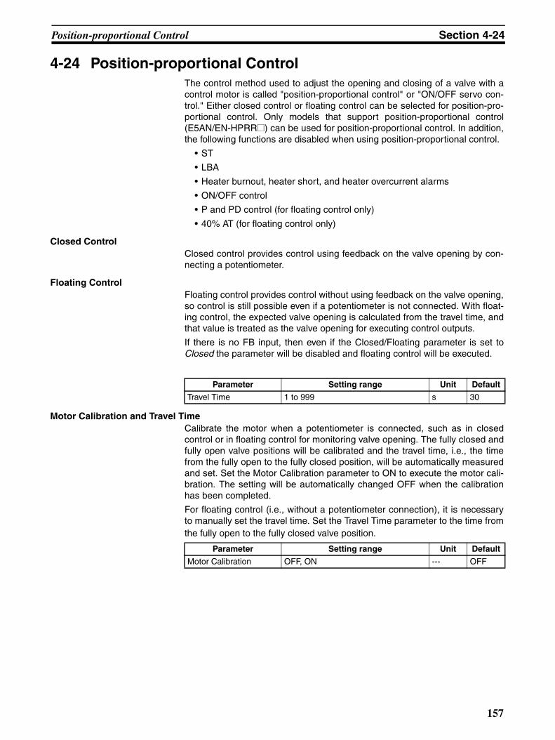
Position-proportional Control Section 4-24
4-24 Position-proportional ControlThe control method used to adjust the opening and closing of a valve with acontrol motor is called "position-proportional control" or "ON/OFF servo con-trol." Either closed control or floating control can be selected for position-pro-portional control. Only models that support position-proportional control(E5AN/EN-HPRR@) can be used for position-proportional control. In addition,the following functions are disabled when using position-proportional control.
• ST
• LBA
• Heater burnout, heater short, and heater overcurrent alarms
• ON/OFF control
• P and PD control (for floating control only)
• 40% AT (for floating control only)
Closed ControlClosed control provides control using feedback on the valve opening by con-necting a potentiometer.
Floating ControlFloating control provides control without using feedback on the valve opening,so control is still possible even if a potentiometer is not connected. With float-ing control, the expected valve opening is calculated from the travel time, andthat value is treated as the valve opening for executing control outputs.
If there is no FB input, then even if the Closed/Floating parameter is set toClosed the parameter will be disabled and floating control will be executed.
Motor Calibration and Travel TimeCalibrate the motor when a potentiometer is connected, such as in closedcontrol or in floating control for monitoring valve opening. The fully closed andfully open valve positions will be calibrated and the travel time, i.e., the timefrom the fully open to the fully closed position, will be automatically measuredand set. Set the Motor Calibration parameter to ON to execute the motor cali-bration. The setting will be automatically changed OFF when the calibrationhas been completed.
For floating control (i.e., without a potentiometer connection), it is necessaryto manually set the travel time. Set the Travel Time parameter to the time fromthe fully open to the fully closed valve position.
Parameter Setting range Unit Default
Travel Time 1 to 999 s 30
Parameter Setting range Unit Default
Motor Calibration OFF, ON --- OFF
157

Position-proportional Control Section 4-24
Position-proportional Dead Band and Open/Close HysteresisThe interval during which the valve output is held (for the ON and OFF switch-ing points for the open output and closed output) is set by the Position Propor-tional Dead Band parameter, and the hysteresis is set by the Open/CloseHysteresis parameter.
PV Dead BandWhen the process value (PV) is within the PV dead band, control is executedas if the process value is equal to the set point for the current bank to preventunnecessary outputs when the process value is in the vicinity of the set point.
Valve Opening MonitorValve opening can be monitored by connecting a potentiometer. The motormust be calibrated after the potentiometer is connected.
Note If no potentiometer is connected or if a potentiometer input error oc-curs, "---- " will be displayed.
With the E5AN/EN-H, valve opening can also be monitored on the PV/SP/MV(Valve Opening) Screen.
Parameter Setting range Unit Default
Position Proportional Dead Band
Position proportional (closed): 0.1 to 10.0
% 4.0
Position proportional (floating): 0.1 to 10.0
2.0
Open/Close Hysteresis 0.1 to 20.0 % 0.8
0
Dead band
−100%
OFF
ON
100%MV − Valve opening
Open/close positional-proportional hysteresis
Parameter Setting range Unit Default
PV Dead Band 0 to 32400 EU 0.0
PV dead bandSP
Parameter Setting range Unit Default
Valve Opening Monitor −10.0 to 110.0 % ---
158

Logic Operations Section 4-25
Manual OperationWith models that support position-proportional control, manual operation ispossible by moving to the manual control level and pressing the Up and DownKeys. The output on the open side is ON while the Up Key is pressed, and theoutput on the closed side is ON while the Down Key is pressed. If the DirectSetting of Position Proportional MV parameter is set to ON and closed controlis used, however, the Manual MV parameter can be set with the same displayand operations as for standard models.
MV at Stop and ErrorWith floating control or when the Direct Setting of Position Proportional MVparameter is set to OFF, select to output open, closed, or hold status whenstopped or when an error occurs. If the Direct Setting of Position ProportionalMV parameter is set to ON for closed control, set the MV.
4-25 Logic Operations
4-25-1 The Logic Operation Function (CX-Thermo)• The logic operation function logically calculates as 1 or 0 the Controller
status (alarms, SP ramp, RUN/STOP, auto/manual, etc.) and the externalevent input status, and outputs the results to work bits. The work bit statuscan be output to auxiliary or control outputs, and operating status can beswitched according to the work bit status.
• Work bit logic operation can be set from 1 to 8. Set them to No operation(Always OFF) (the default) when the work bits are not to be used. Whenlogic operations are being used, a dot will be displayed on the No. 2 dis-play of the adjustment level display
4-25-2 Using Logic OperationsLogic operations are set using the CX-Thermo.
Starting Logic Operations
There are two ways to start logic operations.
• Select Logic Operation Editor from the CX-Thermo tree, and click theStart Button.
l.adj.
Dot displayed.
Adjustment level displayAdjustment Level
159

Logic Operations Section 4-25
• Select Logic Operation Editor from the CX-Thermo Options Menu.
Making the Settings The following display will appear on the Logic Operation Editor Setting Win-dow. Set each of the parameters.
1,2,3... 1. Displaying the Library Import Dialog Box
Logic operation samples for specific cases are set in the library in advance.Examples of settings for specific cases are loaded by selecting them fromthe library list and clicking the OK Button.
A
BC
D
E
F
G H
I
J
K L
M
N
O
160

Logic Operations Section 4-25
Example: Selecting Library 1
2. Switching Work Bit Operations
Select the work bit logic operations from the Operation of Work Bit 1 to Op-eration of Work Bit 8 Tab Pages.
3. Selecting the Operation Type
From one to four operations are supported. If work bits are not to be used,set them to No operation (Always OFF) (the default).
• No Operation (Always OFF)
• Operation 1
• Operation 2
(A and B) or (C and D) When conditions A and B or conditions C and D are satisfied
(A or C) and (B or D)
When condition A or C and condition B or D are satisfied
161

Logic Operations Section 4-25
• Operation 3
• Operation 4
A or B or C or D
When condition A, B, C or D is satisfied
A and B and C and D
When conditions A, B, C and D are all satisfied
162

Logic Operations Section 4-25
4. Selecting Input Assignments
Select the input assignment for the work bit logic operation from the follow-ing settings.
Note (1) The event inputs that can be used depend on the Controller model.
Parameter name
Setting range
Work Bit 1 Input Assignment A
0: Always OFF1: Always ON
2: ON for one cycle when power is turned ON
3: Event Input 1 (external input) (See note 1.)4: Event Input 2 (external input) (See note 1.)
5: Event Input 3 (external input) (See note 1.)
6: Event Input 4 (external input) (See note 1.)7: Alarm 1
8: Alarm 2
9: Alarm 310: Control output ON/OFF count alarm (See note 2.)
11: Control output (heating)
12: Control output (cooling)13: Input error
14: RSP input error
15: HB (heater burnout) alarm16: HS alarm
17: OC (heater overcurrent) alarm
18: Auto/Manual19: RUN/STOP
20: RSP/LSP
21: Program start
22: AT Execute/Cancel23: SP ramp operating
24: Bank No. (bit 0)
25: Bank No. (bit 1)26: Bank No. (bit 2)
27: Program end output
28: Work bit 129: Work bit 2
30: Work bit 3
31: Work bit 432: Work bit 5
33: Work bit 6
34: Work bit 735: Work bit 8
Work Bit 1 Input Assignment B
Same as for work bit 1 input assignment A
Work Bit 1 Input Assignment C
Same as for work bit 1 input assignment A
Work Bit 1 Input Assignment D
Same as for work bit 1 input assignment A
to to
Work Bit 8 Input Assignment D
Same as for work bit 1 input assignment A
163

Logic Operations Section 4-25
(2) Turns ON when either the control output 1 or 2 ON/OFF count alarm isON.
5. Switching between Normally Open and Normally Closed for Inputs A to D
Click the condition to switch between normally open and normally closedinputs A to D.
6. Switching between Normally Open and Normally Closed for Work Bits
Click the condition to switch between normally open and normally closedwork bits.
7. Setting ON Delay Times
When an input with an ON delay turns ON, the output will turn ON after theset delay time has elapsed. The setting range is 0 to 9,999. The default is0 (disabled).
8. Setting OFF Delay Times
When an input with an OFF delay turns OFF, the output will turn OFF afterthe set delay time has elapsed. The setting range is 0 to 9,999. The defaultis 0 (disabled).
9. Switching ON/OFF Delay Time Unit
Select either seconds or minutes for the ON/OFF delay time unit. The de-fault is seconds.
10. Selecting the Number of Banks to Use
Select a number from 0 to 3 for the Bank Numbers Used parameter. (For models with two event inputs, select a number between 0 and 2.)
Note If a work bit is assigned for either the Event Input Data 1 or EventInput Data 2 parameter for a model that does not support event in-puts 1 and 2 and if a number greater than 0 is set for the Bank Num-bers Used parameter, then event inputs 1 and 2 will be used forbank selection.
For example, if the Bank Numbers Used parameter is set to 2 for a modelwith event inputs 3 and 4, and the following settings are made, then eventinput 1 (work bit 1) and event input 2 (work bit 2) will be used for bank se-lection.
• Event Input Data 1: Work bit 1
• Event Input Data 2: Work bit 2
• Event Input Data 3: Event input 3 (external input)
• Event Input Data 4: Event input 4 (external input)
To use event input 3 (external input) and event input 4 (external input) forbank selection, make the following settings:
• Event Input Data 1: Event input 3 (external input)
• Event Input Data 2: Event input 4 (external input)
• Event Input Data 3: Work bit 1
• Event Input Data 4: Work bit 2
Normally open Normally closed
Normally open Normally closed
164

Logic Operations Section 4-25
11. Changing Event Input Data
Select the event input conditions from the following setting ranges.
Note The event input data can be changed from the default setting evenif there is no event input terminal (external input). By changing thedefault setting, the event input assignment parameters will be dis-played at the Controller display and can be set from the Controller.
12. Changing the Event Input Assignment Function
Select the setting for the event input assignment.When a work bit is selected as event input data, Communications WriteEnable/Disable cannot be assigned to an event input.
13. Changing Control Output and Auxiliary Output Settings
Control output and auxiliary output assignments can be changed. Theitems that can be changed depend on the Controller model. For details, re-fer to 3-5-3 Assigned Output Functions.
Assigning a work bit to either a control output or to an auxiliary output isalso considered to be the same as assigning an alarm. For example, ifwork bit 1 is set for the Auxiliary Output 1 Assignment parameter, thenalarms 1 to 3 have been assigned.
14. Displaying Parameter Guides
A description of the parameters can be displayed.
15. Displaying the Work Bit Use Destinations
Display a list of destinations where the work bits are used.
Operating Procedure This procedure uses event input 2 to change to RUN or STOP.
Event input 2 ON: RUN
Event input 2 OFF: STOP
Parameter name Setting range
Event Input Data 1 0: Not assigned.
1: Event input 1 (external input)2: Event input 2 (external input)
3: Event input 3 (external input)
4: Event input 4 (external input)5: Work bit 1
6: Work bit 2
7: Work bit 38: Work bit 4
9: Work bit 5
10: Work bit 611: Work bit 7
12: Work bit 8
Event Input Data 2 Same as for event input data 1
Event Input Data 3 Same as for event input data 1
Event Input Data 4 Same as for event input data 1
165

Logic Operations Section 4-25
Event 2 Work bit 1
Always OFF
Reverse operation
Always OFF
Always OFF
1. Select Logic Operation Editor from the CX-Thermotree, and click the Start Button.
2. The Logic Operation Editor will be displayed. Confirmthat the screen for work bit 1 is displayed, and selectOperation 3 from the Operation Type Field.
3. Set the operation by selecting one of the following:
Work bit 1 input assignment A = 4: Event input 2 (ex-ternal input)
Work bit 1 input assignment B = 0: Always OFF
Work bit 1 input assignment C = 0: Always OFF
Work bit 1 input assignment D = 0: Always OFF
4. Invert work bit 1. Click (Normally open) to change
it to (Normally closed).
5. Assign RUN/STOP to event input 2. Set “5: Work bit 1”for the event input data for event input 2, and set “RUN/STOP” for the assignment function.
6. Closing the Logic Operation Editor Dialog BoxClick the Close Button.
This completes the procedure for setting parametersusing the CX-Thermo. Transfer the settings to the Control-ler to set the Controller. Refer to CX-Thermo help for theprocedure to transfer the settings.
166

Logic Operations Section 4-25
Operating Procedure This procedure outputs alarm 1 status to auxiliary output 1 during operation(RUN). A library object is used to make the setting.
Alarm 1 RUN/STOP Work bit 1
Always OFF Always OFF
1. Select Logic Operation Editor from the CX-Thermotree, and click the Start Button.
2. Click the Import of Library Button.
3. Select Library 1 from the library list, and then click theOK Button.
Confirm the following settings, and then click the OKButton.
Work bit 1 operation type: Operation 1
Work bit 1 input assignment A = 7: Alarm 1
Work bit 1 input assignment B = 19: Invert for RUN/STOP
Work bit 1 input assignment C = 0: Always OFF
Work bit 1 input assignment D = 0: Always OFF
Auxiliary output 1 = Work bit 1
4. Closing the Logic Operation Editor Dialog BoxClick the Close Button.
This completes the procedure for setting parametersusing the CX-Thermo. Transfer the settings to the Control-ler to set the Controller. Refer to CX-Thermo help for theprocedure to transfer the settings.
167

Logic Operations Section 4-25
168

SECTION 5Parameters
This section describes the individual parameters used to setup, control, and monitor operation.
5-1 Conventions Used in this Section . . . . . . . . . . . . . . . . . . . . . . . . . . . . . . . . . . 170
5-1-1 Meanings of Icons Used in this Section . . . . . . . . . . . . . . . . . . . . . . 170
5-1-2 About Related Parameter Displays . . . . . . . . . . . . . . . . . . . . . . . . . . 170
5-1-3 The Order of Parameters in This Section . . . . . . . . . . . . . . . . . . . . . 170
5-1-4 Alarms. . . . . . . . . . . . . . . . . . . . . . . . . . . . . . . . . . . . . . . . . . . . . . . . 170
5-2 Protect Level . . . . . . . . . . . . . . . . . . . . . . . . . . . . . . . . . . . . . . . . . . . . . . . . . . 171
5-3 Operation Level. . . . . . . . . . . . . . . . . . . . . . . . . . . . . . . . . . . . . . . . . . . . . . . . 175
5-4 Adjustment Level . . . . . . . . . . . . . . . . . . . . . . . . . . . . . . . . . . . . . . . . . . . . . . 190
5-5 Bank Setting Level . . . . . . . . . . . . . . . . . . . . . . . . . . . . . . . . . . . . . . . . . . . . . 209
5-6 PID Setting Level . . . . . . . . . . . . . . . . . . . . . . . . . . . . . . . . . . . . . . . . . . . . . . 216
5-7 Monitor/Setting Item Level . . . . . . . . . . . . . . . . . . . . . . . . . . . . . . . . . . . . . . . 220
5-8 Manual Control Level . . . . . . . . . . . . . . . . . . . . . . . . . . . . . . . . . . . . . . . . . . . 221
5-9 Initial Setting Level. . . . . . . . . . . . . . . . . . . . . . . . . . . . . . . . . . . . . . . . . . . . . 223
5-10 Advanced Function Setting Level . . . . . . . . . . . . . . . . . . . . . . . . . . . . . . . . . . 242
5-11 Communications Setting Level . . . . . . . . . . . . . . . . . . . . . . . . . . . . . . . . . . . . 281
169

Conventions Used in this Section Section 5-1
5-1 Conventions Used in this Section
5-1-1 Meanings of Icons Used in this SectionDescribes the functions of the parameter.
Describes the setting range and default of the parameter.
Used to indicate parameters used only for monitoring.
Describes the parameter settings, such as those for Operation Commands,and procedures.
Used to indicate information on descriptions in which the parameter is used orthe names of related parameters.
5-1-2 About Related Parameter DisplaysParameters are displayed only when the conditions for use given on the rightof the parameter heading are satisfied. Protected parameters are not dis-played regardless of the conditions for use, but the settings of these parame-ters are still valid.
5-1-3 The Order of Parameters in This SectionParameters are described level by level.
The first page of each level describes the parameters in the level and the pro-cedure to switch between parameters.
5-1-4 AlarmsIt will be specified in this section when alarms are set for the Control Output 1or 2 Assignment parameters, or for the Auxiliary Output 1 or 3 Assignmentparameters. For example, when alarm 1 is set for the Control Output 1 Assign-ment parameter, it will be specified that alarm 1 is assigned.
Assigning a work bit to either control output 1 or 2 or to auxiliary output 1 to 3is also considered to be the same as assigning an alarm. For example, if workbit 1 is set for the Auxiliary Output 1 Assignment parameter, then alarms 1 to 3have been assigned.
Function
Setting
Monitor
Operation
SeeSee
at
Displayed symbol
AT Execute/Cancel
Parameter name
The E5CN-H must be in operation, and control must be 2-PID control.
Conditions for use
170

Protect Level Section 5-2
5-2 Protect LevelFour levels of protection are provided on the E5CN-H, operation/adjustmentprotect, initial setting/ communications protect, setting change protect, and PFkey protect (PF Key protect is supported for the E5AN-H and E5EN-H only).These protect levels prevent unwanted operation of the keys on the frontpanel in varying degrees.
To move from the operation level to the protect level, press O and M Keys forthree seconds (see note) or more.
Note The time taken to move to the protect level can be adjusted by changing theMove to Protect Level Time parameter setting.
Parameters that are protected will not be displayed and their settings cannotbe changed.
Control in Progress
Protect Level
Press the O + M Keys for at least 1 s.
Press the O + M keys; display will flash.
Press the O + M Keys for at least 3 s. (See note.)
25.0100.0
C
Power ON
Operation LevelAdjustment
Level
PID Setting Level
Bank Setting Level
Press the O Key for at least 1 s.
Note The time to press the Key can be changed using the Move to Protect Level Time parameter.
Protect Level
M
M
M
M
M
M
M
pmov0
oapt0
icpt0
wtptoff
pmskon
prlp0
pfptoff
Page
Move to Protect LevelDisplayed only when a password is set.
Operation/Adjustment Protect
Initial Setting/ Communications Protect
Setting Change Protect
Parameter Mask Enable
Password to Move to Protect Level
PF Key Protect
172
172
172
173
173
174
173
171

Protect Level Section 5-2
The password to move to the protect level is entered for this parameter.
• The password to move to the protect level (i.e., the password set for thePassword to Move to Protect Level parameter) is entered for this parame-ter.
• The Operation/Adjustment Protect parameter will be displayed if the cor-rect password is entered.
Related Parameters
Password to move to protect level (protect level): Page 174
These parameters specify the range of parameters to be protected. Shadedsettings are the defaults.
Operation/Adjustment Protect
The following table shows the relationship between set values and the rangeof protection.
• Parameters are not protected when the set value is set to 0.
Initial Setting/Communications Protect
This protect level restricts movement to the initial setting level, communica-tions setting level, and advanced function setting level.
pmov Move to Protect Level The Password to Move to Protect Level password must not be set to 0.
Function
SeeSee
oapt Operation/Adjustment Protecticpt Initial Setting/Communications Protect
Function
Setting
Level Set value
0 1 2 3
Operation Level
PV Can be displayed Can be displayed Can be displayed Can be displayed
PV/SP Can be displayed and changed
Can be displayed and changed
Can be displayed and changed
Can be displayed
Others Can be displayed and changed
Can be displayed and changed
Cannot be dis-played and moving to other levels is not possible
Cannot be dis-played and moving to other levels is not possible
Adjustment Level Can be displayed and changed
Cannot be dis-played and moving to other levels is not possible
Cannot be dis-played and moving to other levels is not possible
Cannot be dis-played and moving to other levels is not possible
Set value
Initial setting level Communications setting level
Advanced function setting level
0 Possible to reach Possible to reach Possible to reach
1 Possible to reach Possible to reach Not possible to reach
2 Not possible to reach Not possible to reach Not possible to reach
172

Protect Level Section 5-2
This parameter specifies the range of data to be protected. The shaded cellindicates the default.
Change Setting Protect
Changes to settings using key operations are restricted.
When enabling and disabling of setting changes by event inputs assignment 1to 4 is selected, this parameter is not displayed.
• The all protect indication ( ) will light when setting is ON.
PF Key Protect
This parameter enables and disables PF Key operation (E5AN/EN-H only).
• The shaded cell indicates the default.
• This parameter turns the parameter mask function ON and OFF.
Note A parameter mask can be used to hide the displays of parameters that are notneeded. The parameter mask function is provided by the Setup Tool. Setup Tool: CX-Thermo (EST2-2C-MV4)
wtpt Setting Change ProtectThe Event Input Assignment 1 to 4 parameters must not be set to “set-ting change enable/disable.”
Function
Set value Description
OFF Settings can be changed using key operations.
ON Settings cannot be changed using key operations. (The protect level settings, however, can be changed.) Setting
pfpt PF Key Protect The Controller must have a PF Key (E5AN/EN-H).
Function
Set value Description
OFF PF Key enabled
ON PF Key disabled (Operation as a function key is prohibited.)Setting
pmsk Parameter Mask EnableThis parameter is displayed only when a parameter mask has been set from the Setup Tool.
Setting range Default
on: Enabled, off: Disabled on
Function
Setting
173

Protect Level Section 5-2
This parameter is used to set the password to move to the protect level.
• To prevent setting the password incorrectly, the U and O Keys or D andO Keys must be pressed simultaneously to set the password.
• Set this parameter to 0 when no password is to be set.
Related Parameters
Move to protect level (protect level): Page 172
Note Protection cannot be cleared or changed without the password. Be careful notto forget it. If you forget the password, contact your OMRON sales representa-tive.
prlp Password to Move to Protect Level
Setting range Default
−1999 to 9999 0
Function
Setting
SeeSee
174

Operation Level Section 5-3
5-3 Operation LevelDisplay this level to perform control operations. You can set alarm values,monitor the manipulated variable, and perform other operations in this level.
In the advanced function setting level, you can set a parameter to hide orshow the set points.
This level is displayed immediately after the power is turned ON.
To move to other levels, press the O Key or the O and M Keys.
Control in progress
Control stopped
Operation Level
Initial Setting Level
Control stops.
Communi- cations Setting Level
Adjustment Level
Power ON
Press the O Key less than 1 s.
Press the O Key for at least 1 s.
Press the O Key for at least 1 s; display will flash.
Press the O Key for at least 3 s.
Press the O Key for less than 1 s.
PID Setting Level
Bank Setting Level
25100
C
175

Operation Level Section 5-3
Note For details on the displays of Controllers with a No. 3 display (E5AN/EN-H),refer to Process Value/Set Point on page 177.
Operation Level
Page Page
al1l0.0
c
M
M
M
M
M
M
M
M
M
M
M
M
M
M
M
M
M
M
M
M
M
M
M
M
M
25.0c
25.0
0.0
c
a-m
bank0
rsp0.0
sp-m0.0
ct10.0
ct20.0
lcr10.0
lcr2
0.0
prstrset
sktr
0
r-s
run
al-10.0
c
al-20.0
c
al2h0.0
c
al2l0.0
c
al-30.0
c
al3h
0.0
al3l
0.0
o0.0
c-o
0.0
v-m
0.0
al1h0.0
c
c
Process ValueAdded when Additional PV display is ON.
Process Value/ Set Point
Auto/Manual Switch
Set Point During SP Ramp
Heater Current 1 Value Monitor
Heater Current 2 Value Monitor
Leakage Current 1 Monitor
Leakage Current 2 Monitor
Program Start
Soak Time Remain
RUN/STOP
Alarm Value 1
Alarm Value Upper Limit 1
Alarm Value Lower Limit 1
Alarm Value 2
Alarm Value Upper Limit 2
Alarm Value Lower Limit 2
Alarm Value 3
Alarm Value Upper Limit 3
Alarm Value Lower Limit 3
MV Monitor (Heating)
MV Monitor (Cooling)
Bank No.
Remote SP Monitor
Valve Opening Monitor
177
177
178
179
179
180
182
181
183
183
184
184
185
185
187
187
186
187
187
186
188
188
188
189
176

Operation Level Section 5-3
The process value is displayed on the No. 1 display, and nothing is displayedon the No. 2 and No. 3 (E5AN/EN-H only) displays.
During temperature input, the decimal point position depends on the currentlyselected sensor, and during analog input it depends on the Decimal Pointparameter setting.
Related Parameters
Input type: Page 224, Set point upper limit, Set point lower limit: Page 227 (ini-tial setting level)
The process value is displayed on the No. 1 display, and the set point is dis-played on the No. 2 display.
During temperature input, the decimal point position depends on the currentlyselected sensor, and during analog input it depends on the Decimal Pointparameter setting.
No. 3 Display (E5AN/EN-H)
The following table shows the contents of the No. 3 display, according to thesetting of the PV/SP Display Screen Selection parameter.
Process Value The Additional PV Display parameter must be set to ON.
Monitor range Unit
Process value Temperature: According to indication range for each sensor.Analog: Scaling lower limit −5% FS to Scaling upper limit +5% FS (Refer to page 335.)
EU
Function
Monitor
SeeSee
Process Value/Set Point (Display 1) (The Process Value/Set Point (Dis-play 2) parameter is supported for the E5AN-H and E5EN-H only.)Process Value/Set Point (Display 2)
Monitor range Unit
Process value Temperature: According to indication range for each sensor.Analog: Scaling lower limit −5% FS to Scaling upper limit +5% FS (Refer to page 335.)
EU
Setting range Unit
Set point SP lower limit to SP upper limit EU
Set value Display contents
0 Only the PV and SP are displayed. (The No. 3 display is not shown.)
1 PV/SP/Bank No. and PV/SP/MV are displayed in order.
Function
Monitor
177

Operation Level Section 5-3
When 1, 2, 5, or 6 is selected, press the M Key to display PV/SP (Display 2).
Example: When the PV/SP Display Screen Selection Parameter Is Set to 2
Related Parameters
Input type: Page 224, Set point upper limit, Set point lower limit: Page 227 (ini-tial setting level)
PV/SP display screen selection (advanced function setting level): Page 275
• This parameter switches the Controller between automatic and manualmodes.
• If the O Key is pressed for at least 3 seconds when the Auto/ManualSwitch parameter is displayed, the manual mode will be entered and themanual control level will be displayed.
• This parameter will not be displayed if an event input is set to “MANU”(auto/manual).
Related Parameters
PID ON/OFF (initial setting level): Page 228
Auto/manual select addition (advanced function setting level): Page 256
2 PV/SP/MV and PV/SP/Bank No. are displayed in order.
3 Only PV/SP/Bank No. are displayed.
4 PV/SP/MV are displayed
5 PV/SP/Bank No. and PV/SP/Soak time remain are displayed in order.
6 PV/SP/MV and PV/SP/Soak time remain are displayed in order.
7 Only PV/SP/Soak time remain are displayed.
Set value Display contents
25.0100.0
50.0
25.0100.0
0
MPress the key.
Operation Level PV/SP (Display 1)
PV/SP/MV PV/SP/Bank No.
C C
PV/SP (Display 2)
SeeSee
a-m Auto/Manual Switch
The Event Input Assignment 1 to 4 parameters must not be set to Auto/Manual and the Auto/Manual Select Addition parameter must be set to ON. The control must be set to 2-PID control.
Operation
SeeSee
178

Operation Level Section 5-3
• This parameter is used to select the bank. The SP, PID set number, SPramp set value, alarm value, soak time, and wait band are set in bank set-ting level for each bank to be used, and then operation is switchedbetween the banks using bank specifications (with event inputs, key oper-ations, or communications).
• With this parameter, the bank is specified by using key operations.
• Use the U and D Keys to specify the bank number.
• The default is for the current bank number to be displayed.
Related Parameters
Bank numbers used (advanced function setting level): Page 237
• This parameter monitors the remote SP while in Local SP Mode.
• While in Remote SP Mode, the remote SP can be monitored on the No.2 display of the PV/SP Screen.
Related Parameters
Process value/Set point (operation level): Page 177
SP mode (adjustment level): Page 193Remote SP upper limit, Remote SP lower limit (advanced function settinglevel): Page 267Remote SP enable (advanced function setting level): Page 266
bank Bank No. The Bank Numbers Used parameter must be set to 0.
Function
Operation
SeeSee
rsp Remote SP Monitor
The ST parameter must be set to OFF.The Remote SP Enable parameter must be set to ON.
The SP Mode parameter must be set to LSP.
Monitor range Unit
Remote SP lower limit to remote SP upper limitThere are restrictions on the SP limits.
EU
Function
Monitor
SeeSee
179

Operation Level Section 5-3
This parameter monitors the set point during SP ramp operation.
A ramp is used to restrict the change width of the set point as a rate ofchange.
This parameter is displayed when a set value is input for the Bank * SP RampSet Value parameter (bank setting level).
When not in ramp operation, the set point will be the same as the one dis-played for the Process Value/Set Point parameter.
Related Parameters
Process value/Set point (operation level): Page 177
Bank * SP ramp set value (bank setting level): Page 211
Set point upper limit, Set point lower limit (initial setting level): Page 227
sp-m Set Point During SP Ramp
The Bank * SP Ramp Set Value parameter must not be set to OFF, or the Remote SP Enable parameter must be set to ON.
The ST parameter must be set to OFF.
Monitor range Unit
SP: SP lower limit to SP upper limit EU
Function
Monitor
SeeSee
180

Operation Level Section 5-3
This parameter measures the heater current from the CT input used fordetecting heater burnout.
This parameter measures and displays the heater current value.
• Heater burnouts and heater overcurrent are not detected if the controloutput (heating) ON time is 100 ms or less.
• ffff is displayed when 55.0 A is exceeded.
• If a heater burnout detection 1 or heater overcurrent detection 1 alarm isoutput, the HA indicator will light and the No. 1 display for the heater cur-rent 1 value monitor will flash.
Related Parameters
Heater burnout detection 1, Heater burnout detection 2 (adjustment level):Page 194, 196
HB ON/OFF (advanced function setting level): Page 246
Heater overcurrent detection 1, Heater overcurrent detection 2 (adjustmentlevel): Page 195
Heater overcurrent use (advanced function setting level): Page 272
Error displays ct1: Page 306
ct1 Heater Current 1 Value Monitor
Heater burnout, HS alarm, and heater overcurrent detection must be supported. Alarm 1 must be assigned.The Heater Burnout Detection or Heater Overcurrent Use parameter must be set to ON.
Monitor range Unit
0.0 to 55.0 A
Function
Monitor
SeeSee
181

Operation Level Section 5-3
This parameter measures the heater current from the CT input used fordetecting heater burnout.
This parameter measures and displays the heater current value.
• Heater burnouts and heater overcurrent are not detected if the controloutput (heating) ON time is 100 ms or less.
• ffff is displayed when 55.0 A is exceeded.
• If a heater burnout detection 2 or heater overcurrent detection 2 alarm isoutput, the HA indicator will light and the No. 1 display for the heater cur-rent 2 value monitor will flash.
Related Parameters
Heater burnout detection 1, Heater burnout detection 2 (adjustment level):Page 194, 196
HB ON/OFF (advanced function setting level): Page 246
Heater overcurrent detection 1, Heater overcurrent detection 2 (adjustmentlevel): Page 195, 196
Heater overcurrent use (advanced function setting level): Page 272
Error displays ct2: Page 306
ct2 Heater Current 2 Value Monitor
Heater burnout, HS alarm, and heater overcurrent detection must be supported (two CTs). Alarm 1 must be assigned. The Heater Burnout Detection or Heater Overcurrent Use parameter must be set to ON.
Monitor range Unit
0.0 to 55.0 A
Function
Monitor
SeeSee
182

Operation Level Section 5-3
This parameter measures the heater current from the CT input used fordetecting SSR short-circuits.
The heater current is measured and the leakage current 1 monitor is dis-played.
• HS alarms are not detected if the control output (heating) OFF time is100 ms or less.
• ffff is displayed when 55.0 A is exceeded.
• If an HS alarm 1 alarm is output, the HA indicator will light and the No. 1display for the leakage current 1 monitor will flash.
Related Parameters
HS alarm 1, HS alarm 2 (adjustment level): Page 197
Failure detection (advanced function setting level): Page 257
Error displays lcr1: Page 306
This parameter measures the heater current from the CT input used fordetecting SSR short-circuits.
This parameter measures and displays the heater current value.
• HS alarms are not detected if the control output (heating) OFF time is100 ms or less.
• ffff is displayed when 55.0 A is exceeded.
• If an HS alarm 2 alarm is output, the HA indicator will light and the No. 1display for the leakage current 2 monitor will flash.
Related Parameters
HS alarm 1, HS alarm 2 (adjustment level): Page 197
HS alarm use (advanced function setting level): Page 257
Error displays lcr2: Page 306
lcr1 Leakage Current 1 Monitor
Heater burnout, HS alarms, and heater overcurrent detection must be supported. The HS Alarm Use parameter must be set to ON.
Monitor range Unit
0.0 to 55.0 A
Function
Monitor
SeeSee
lcr2 Leakage Current 2 Monitor
Heater burnout, HS alarms, and heater overcurrent detection must be supported (two CTs).Alarm 1 must be assigned. The HS Alarm Use parameter must be set to ON.
Monitor range Unit
0.0 to 55.0 A
Function
Monitor
SeeSee
183

Operation Level Section 5-3
This parameter starts and stops the simple program function.
• The RUN/STOP status will automatically switch to RUN when this param-eter is set to STRT.
• The simple program will stop when this parameter is set to RSET.
• This parameter will function as a monitor display for the start/stop statusof the simple program if an event input is selected to start the simple pro-gram.
Related Parameters
Soak time remain: Page 184, RUN/STOP: Page 185 (operation level)
Bank * soak time, Wait band (bank setting level): Page 215
Program pattern (initial setting level): Page 229
Soak time unit (advanced function setting level): Page 266
• This parameter measures and displays the remaining time of the soaktime for the simple program function.
Related Parameters
Program start (operation level): Page 184
Bank * soak time, Wait band (bank setting level): Page 215
Program pattern (initial setting level): Page 229
Soak time unit (advanced function setting level): Page 266
prst Program Start The Program Pattern parameter must not be set to OFF.
Setting range Default
RSET Stops the simpler program. rset
STRT Starts the simpler program.
Function
Operation
SeeSee
sktr Soak Time Remain The Program Pattern parameter must not be set to OFF.
Monitor range Unit
0 to 9999 min or h
Function
Monitor
SeeSee
184

Operation Level Section 5-3
This parameter starts and stops the control operation.
When run (RUN) is selected, control is started. When stop (STOP) isselected, control is stopped. The STOP indicator will light when control.
The default is run.
This parameter will not be displayed if an event input is set to “RUN/STOP.”
This parameter is set to one of the input values “X” in the alarm type list.
• This parameter sets the alarm value for alarm 1.
• During temperature input, the decimal point position depends on the cur-rently selected sensor, and during analog input it depends on the DecimalPoint parameter setting.
• The set value is saved in the Alarm 1 parameter in the current bank.
Related Parameters
Input type: Page 224, Scaling upper limit, Scaling lower limit, Decimal point(initial setting level): Page 226 (initial setting level)
Alarm 1 type (initial setting level): Page 231
Standby sequence reset: Page 244, Auxiliary output * open in alarm: Page245, Alarm 1 hysteresis: Page 233, Alarm 1 latch: Page 250 (advanced func-tion setting level)
Bank * alarm value 1 (bank setting level): Page 211
r-s RUN/STOPThe Event Input Assignment 1 to 4 parameters must not be set to “RUN/STOP.”
Operation
SeeSee
al-1 Alarm Value 1Alarm 1 must be assigned. The alarm 1 type must not be 0, 1, 4, 5, or 12.
Setting range Unit Default
−1999 to 9999 EU 0
Function
Setting
SeeSee
185

Operation Level Section 5-3
This parameter is set to one of the input values “X” in the alarm type list.
• This parameter sets the alarm value for alarm 2.
• During temperature input, the decimal point position depends on the cur-rently selected sensor, and during analog input it depends on the DecimalPoint parameter setting.
• The set value is saved in the Alarm 2 parameter in the current bank.
Related Parameters
Input type: Page 224, Scaling upper limit, Scaling lower limit, Decimal point(initial setting level): Page 226 (initial setting level)
Alarm 2 type (initial setting level): Page 233
Standby sequence reset: Page 244, Auxiliary output * open in alarm: Page245, Alarm 2 hysteresis: Page 233, Alarm 2 latch: Page 250 (advanced func-tion setting level)
Bank * alarm value 2 (bank setting level): Page 212
This parameter is set to one of the input values “X” in the alarm type list.
• This parameter sets the alarm value for alarm 3.
• During temperature input, the decimal point position depends on the cur-rently selected sensor, and during analog input it depends on the DecimalPoint parameter setting.
• The set value is saved in the Alarm 3 parameter in the current bank.
Related Parameters
Input type: Page 224, Scaling upper limit, Scaling lower limit, Decimal point(initial setting level): Page 226 (initial setting level)
Alarm 3 type (initial setting level): Page 234
Standby sequence reset: Page 244, Auxiliary output * open in alarm: Page245, Alarm 3 hysteresis: Page 233, Alarm 3 latch: Page 250 (advanced func-tion setting level)
Bank * alarm value 3 (bank setting level): Page 213
al-2 Alarm Value 2Alarm 2 must be assigned. The alarm 2 type must not be 0, 1, 4, 5, or 12.
Setting range Unit Default
−1999 to 9999 EU 0
Function
Setting
SeeSee
al-3 Alarm Value 3Alarm 3 must be assigned. The alarm 3 type must not be 0, 1, 4, 5, or 12.
Setting range Unit Default
−1999 to 9999 EU 0
Function
Setting
SeeSee
186

Operation Level Section 5-3
These parameters independently set the alarm value upper and lower limitswhen the mode for setting the upper and lower limits is selected for the Alarm1 Type parameter (initial setting level).
• This parameter sets the upper and lower limit values of alarm 1.
• During temperature input, the decimal point position depends on the cur-rently selected sensor, and during analog input it depends on the DecimalPoint parameter setting.
• The set value is saved in the Alarm Value Upper Limit 1 and Alarm ValueLower Limit 1 parameters in the current bank.
Related Parameters
Input type: Page 224, Scaling upper limit, Scaling lower limit, Decimal point:Page 226, Alarm 1 type: Page 231 (initial setting level), Standby sequencereset: Page 244, Auxiliary output * open in alarm: Page 245, Alarm 1 hystere-sis: Page 233, Alarm 1 latch: Page 250 (advanced function setting level)
Bank * alarm value upper limit 1, Bank * alarm value lower limit 1 (bank settinglevel): Page 212
These parameters independently set the alarm value upper and lower limitswhen the mode for setting the upper and lower limits is selected for the Alarm2 Type parameter (initial setting level).
• This parameter sets the upper and lower limit values of alarm 2.
• During temperature input, the decimal point position depends on the cur-rently selected sensor, and during analog input it depends on the DecimalPoint parameter setting.
• The set value is saved in the Alarm Value Upper Limit 2 and Alarm ValueLower Limit 2 parameters in the current bank.
al1h Alarm Value Upper Limit 1 Alarm 1 must be assigned. The alarm 1 type must not be 1, 4, or 5.al1l Alarm Value Lower Limit 1
Setting range Unit Default
−19999 to 32400 EU 0.0
Function
Setting
SeeSee
al2h Alarm Value Upper Limit 2 Alarm 2 must be assigned. The alarm 2 type must not be 1, 4, or 5.al2l Alarm Value Lower Limit 2
Setting range Unit Default
−1999 to 9999 EU 0
Function
Setting
187

Operation Level Section 5-3
Related Parameters
Input type: Page 224, Scaling upper limit, Scaling lower limit, Decimal point:Page 226, Alarm 2 type: Page 233 (initial setting level), Standby sequencereset: Page 244, Auxiliary output * open in alarm: Page 245, Alarm 2 hystere-sis: Page 233, Alarm 2 latch: Page 250 (advanced function setting level)
Bank * alarm value upper limit 2, Bank * alarm value lower limit 2 (bank settinglevel): Page 213
These parameters independently set the alarm value upper and lower limitswhen the mode for setting the upper and lower limits is selected for the Alarm3 Type parameter (initial setting level).
• This parameter sets the upper and lower limit values of alarm 3.
• During temperature input, the decimal point position depends on the cur-rently selected sensor, and during analog input it depends on the DecimalPoint parameter setting.
• The set value is saved in the Alarm Value Upper Limit 3 and Alarm ValueLower Limit 3 parameters in the current bank.
Related Parameters
Input type: Page 224, Scaling upper limit, Scaling lower limit, Decimal point:Page 226, Alarm 3 type: Page 234 (initial setting level), Standby sequencereset: Page 244, Auxiliary output * open in alarm: Page 245, Alarm 3 hystere-sis: Page 233, Alarm 3 latch: Page 250 (advanced function setting level)
Bank * alarm value upper limit 3, Bank * alarm value lower limit 3 (bank settinglevel): Page 214
This parameter is used to check the manipulated variable for the heating con-trol output during operation.
• This parameter cannot be set.
• During standard control, the manipulated variable is monitored. Duringheating/cooling control, the manipulated variables on the control output(heating) is monitored.
• The default is OFF and the manipulated variable is not displayed.
SeeSee
al3h Alarm Value Upper Limit 3 Alarm 3 must be assigned. The alarm 3 type must not be 1, 4, or 5.al3l Alarm Value Lower Limit 3
Setting range Unit Default
−1999 to 9999 EU 0
Function
Setting
SeeSee
o MV Monitor (Heating) The MV Display parameter must be set to ON.
Control Monitor range Unit
Standard −5.0 to 105.0 %
Heating/cooling 0.0 to 105.0 %
Function
Monitor
188

Operation Level Section 5-3
Related Parameters
MV display (advanced function setting level): Page 250
This parameter is used to check the manipulated variable for the cooling con-trol output during operation.
• This parameter cannot be set.
• During heating/cooling control, the manipulated variable on the controloutput (cooling) is monitored.
• The default is OFF and the manipulated variable is not displayed.
Related Parameters
Standard or heating/cooling (initial setting level): Page 228
MV display (advanced function setting level): Page 250
This parameter monitors the valve opening during operation.
• This parameter monitors the valve opening when position-proportionalcontrol is used.
• The valve opening can be monitored if a potentiometer is connected andmotor calibration is executed.
Related Parameters
Motor calibration (initial setting level): Page 240
PV/SP display screen selection (advanced function setting level): Page 275
SeeSee
c-o MV Monitor (Cooling)The control system must be set to heating/cooling control.The MV Display parameter must be set to ON.
Control Monitor range Unit
Heating/cooling 0.0 to 105.0 %
Function
Monitor
SeeSee
v-m Valve Opening Monitor
Position-proportional control must be supported. The No. 3 display must be supported.
The PV/SP Display Screen Selection parameter must be set to 1, 2, 4, or 6.
Control Monitor range Unit
Position-proportional −10.0 to 110.0 %
Function
Monitor
SeeSee
189

Adjustment Level Section 5-4
5-4 Adjustment LevelThis level is for executing AT (auto-tuning) and other operations, and for setcontrol parameters.
This Digital Controllers the basic Controller parameters for PID control (pro-portional band, integral time, derivative time) and heating/cooling control.
To move to the adjustment level from the operation level, press the O Keyonce.
• The following parameters are displayed for Controllers with CT Inputs:Heater current monitors, Leakage current monitors, heater burnout detec-tions, HS alarms, and heater overcurrent detections.
• Adjustment level parameters can be changed after setting the Operation/Adjustment Protect parameter to 0. Displays and changing levels are notpossible if the Operation/Adjustment Protect parameter is set to 1 to 3.Protection is set in the protect level.
Power ON
Operation LevelAdjustment
Level
PID Setting Level
Bank Setting Level
Control in progress
Press the O Key for at least 1 s.
190

Adjustment Level Section 5-4
Adjustment Level
Set either of these parame-ters.
PID settings
Hysteresis settings
M
M
M
M
M
M
M
M
M
M
M
M
M
M
M
M
M
M
M
M
M
M
M
M
M
M
l.adj
at
off
cmwtoff
irdaoff
spmdlsp
ct10.0
ins
0.00
c
insh0.00
c
insl0.00
c
p8.0
c
i233.0
d
40.0
c-sc
1.00
c-db
0.0
of-r50.0
hys1.0
chys1.0
soak
1
wt-b
off
mv-s0.0
mv-e0.0
sprt
off
ol-h105.0
ol-l-5.0
db2.0
oc-h0.8
sqrp
0.0
M
orl
M
0.0
M
M
M
M
M
M
M
M
ct20.0
lcr10.0
lcr20.0
hb10.0
hb20.0
hs150.0
hs250.0
oc150.0
oc250.0
M
AT Execute/Cancel
Communications Writing
Heater Current 1 Value Monitor
Heater Burnout Detection 1
Heater OvercurrentDetection 1
Heater Current 2 Value Monitor
Heater Burnout Detection 2
Heater OvercurrentDetection 2
Leakage Current 1 Monitor
Leakage Current 2 Monitor
HS Alarm 1
HS Alarm 2
Temperature Input Shift
Upper Limit Temperature Input Shift Value
Lower Limit Temperature Input Shift Value
Proportional Band
Integral Time
Derivative Time
Cooling Coefficient
Heating/cooling
Dead Band
Manual Reset ValueClear the offset during stabilization of P or PD control.
Hysteresis (Heating)
Hysteresis (Cooling)
Soak Time
Wait Band
MV at Stop
MV at PV Error
SP Ramp Set Value
MV Upper Limit
MV Lower Limit
MV Change Rate Limit
Extraction of Square Root Low-cut Point
Infrared Communications Use
SP Mode
Position Proportional Dead Band
Open/Close Hysteresis
Page Page PageAdjustment Level DisplayDisplayed only once when entering adjustment level.
1-point shift
2-point shift
192
192
193
193
193
194
195
196
196
198
197
198
198
199
199
199
200
200
200
201
201
202
202
202
203
203
204
204
205
205
205
206
207
207
207
194
195
191

Adjustment Level Section 5-4
This parameter is displayed after moving to the adjustment level.
When a logic operation is set, a period "." will be displayed on the No. 2. dis-play.
• This parameter indicates that the adjustment level has been entered.(The Adjustment Level parameter will not be displayed again even if theM Key is pressed in the adjustment level to scroll through the parame-ters.)
This parameter executes auto-tuning (AT).
• The MV is forcibly increased and decreased around the set point to findthe characteristics of the control object. From the results, the PID con-stants are automatically set in the Proportional Band (P), Integral Time (I),and Derivative Time (D) parameters.
• Both 100% AT and 40% AT are supported for AT.
• Only 100% AT can be executed for heating/cooling control and position-proportional floating control.
• This parameter will not be displayed when either 100% or 40% AT exe-cute/cancel is set to be executed using an event input.
• This parameter is normally off. Press the U Key and select at-2 or at-1 to execute AT. AT cannot be executed when control is stopped or duringON/OFF control.
• When AT execution ends, the parameter setting automatically returns tooff.
Related Parameters
PID * proportional band, PID * Integral time, PID * Derivative time (PID settinglevel): Page 217
PID ON/OFF (initial setting level): Page 228
l.adj Adjustment Level Display
Function
at AT Execute/Cancel
The ramp must be in operation, and 2-PID control must be used. Event Input Assignments 1 to 4 parameters must be other than 100% or 40% AT Execute/Cancel.
Setting rage Default
OFF: AT CancelAT-2: 100%AT Execute
AT-1: 40%AT Execute
OFF
Function
Operation
SeeSee
192

Adjustment Level Section 5-4
• This parameter enables/disables writing of parameters to the Digital Con-trollers from the host (personal computer) using communications.
• This parameter is not displayed if communications write enable/disable isset for execution using an event input assignment 1 to 4.
ON: Writing enabled
OFF: Writing disabled
• Default: OFF
Related Parameters
MB command logic switching (advanced function setting level): Page 252
Communications unit No., Communications baud rate, Communications datalength, Communications parity, Communications stop bits (communicationssetting level): Page 281
This parameter enables or disables infrared communications between thehost (personal computer) and the Digital Controller.
• Set this parameter to ON only when connecting to a Setup Tool, and leaveit set to OFF during normal operation.
ON: Infrared communications enabled.
OFF: Infrared communications disabled.
• Default: OFF
• This parameter is used to select the SP mode.
• In Local SP Mode, the local SP set in bank is used as the target value inthe control operation. In Remote SP Mode, the remote SP set via anexternal signal (e.g., 4 to 20 mA) is used as the target value in the controloperation.
cmwt Communications WritingCommunications must be supported.
The Event Input Assignments 1 to 4 parameters must not be set to enable communications writing.
Function
Setting
SeeSee
irdr Infrared Communications Use Infrared communications must be supported.
Function
Setting
spmd SP Mode
The ST parameter must be set to OFF.
The Remote SP Enable parameter must be set to ON.
The Event Input Assignment 1 to 4 parameters must not be set to switch to SP mode.
Setting range Default
RSP: Remote SP, LSP: Local SP LSP
Function
Setting
193

Adjustment Level Section 5-4
Related Parameters
Remote SP enable (advanced function setting level): Page 266
This parameter measures the heater current from the CT input used fordetecting heater burnout.
This parameter measures and displays the heater current value.
• Heater burnouts or heater overcurrent are not detected if the control out-put (heating) ON time is 100 ms or less.
• ffff is displayed when 55.0 A is exceeded.
• If a heater burnout detection 1 or heater overcurrent detection 1 alarm isoutput, the HA indicator will light and the No. 1 display for the heater cur-rent 1 value monitor will flash.
Related Parameters
Heater burnout detection 1, Heater burnout detection 2 (adjustment level):Page 194, 196
HB ON/OFF (advanced function setting level): Page 246
Heater overcurrent detection 1, Heater overcurrent detection 2 (adjustmentlevel): Page 195, 196
Heater overcurrent use (advanced function setting level): Page 272
Error displays ct1: Page 306
This parameter sets the current for the heater burnout alarm to be output.
• The heater burnout alarm is output when the heater current value fallsbelow the setting of this parameter.
• When the set value is 0.0, the heater burnout alarm output is turned OFF.When the set value is 50.0, the heater burnout alarm output is turned ON.
SeeSee
ct1 Heater Current 1 Value Monitor
Heater burnout, HS alarms, and heater overcurrent detection must be supported.
Alarm 1 must be assigned.
The HB ON/OFF parameter or Heater Overcurrent Use parameter must be set to ON.
Monitor range Unit
0.0 to 55.0 A
Function
Monitor
SeeSee
hb1 Heater Burnout Detection 1
Heater burnout, HS alarms, and heater overcurrent detection must be supported.Alarm 1 must be assigned. The Heater Burnout Detection parameter must be set to ON.
Setting range Unit Default
0.0 to 50.0 A 0.0
Function
Setting
194

Adjustment Level Section 5-4
Related Parameters
Heater current 1 value monitor (adjustment level): Page 181
HB ON/OFF, Heater burnout latch, Heater burnout hysteresis (advanced func-tion setting level): Page 246, 247
This parameter sets the current value for heater overcurrent alarm outputs.
• A heater overcurrent alarm is output when the heater current exceeds thevalue set for this parameter.
• When the set value is 50.0, the heater overcurrent alarm is turned OFF.When the set value is 0.0, the heater overcurrent alarm is turned ON.
Related Parameters
Heater current 1 value monitor (adjustment level): Page 181
Heater overcurrent use, Heater overcurrent latch, Heater overcurrent hystere-sis (advanced function setting level): Page 272, 273
This parameter measures the heater current from the CT input used fordetecting heater burnout.
This parameter measures and displays the heater current value.
• Heater burnouts and heater overcurrent are not detected if the controloutput (heating) ON time is 100 ms or less.
• ffff is displayed when 55.0 A is exceeded.
• If a heater burnout detection 2 or heater overcurrent detection 2 alarm isoutput, the HA indicator will light and the No. 1 display for the heater cur-rent 2 value monitor will flash.
SeeSee
oc1 Heater Overcurrent Detection 1
Heater burnout, HS alarms, and heater overcurrent detection must be supported.
Alarm 1 must be assigned.
The Heater Overcurrent Use ON/OFF parameter must be set to ON.
Setting range Unit Default
0.0 to 50.0 A 50.0
Function
Setting
SeeSee
ct2 Heater Current 2 Value Monitor
Heater burnout, HS alarms, and heater overcurrent detection must be supported (two CTs).
Alarm 1 must be assigned.
The HB ON/OFF or Heater Overcur-rent Use parameter must be set to ON.
Monitor range Unit
0.0 to 55.0 A
Function
Monitor
195

Adjustment Level Section 5-4
Related Parameters
Heater burnout detection 1, Heater burnout detection 2 (adjustment level):Page 194, 196
HB ON/OFF (advanced function setting level): Page 246
Heater overcurrent detection 1, Heater overcurrent detection 2 (adjustmentlevel): Page 195, 196
Heater overcurrent use (advanced function setting level): Page 272
Error displays ct2: Page 306
This parameter sets the current for the heater burnout alarm to be output.
• The heater burnout alarm is output when the heater current value fallsbelow the setting of this parameter.
• When the set value is 0.0, the heater burnout alarm output is turned OFF.When the set value is 50.0, the heater burnout alarm output is turned ON.
Related Parameters
Heater current 2 value monitor (adjustment level): Page 182
HB ON/OFF, Heater burnout latch, Heater burnout hysteresis (advanced func-tion setting level): Page 246
This parameter sets the current value for heater overcurrent alarm outputs.
• A heater overcurrent alarm is output when the heater current exceeds thevalue set for this parameter.
• When the set value is 50.0, the heater overcurrent alarm is turned OFF.When the set value is 0.0, the heater overcurrent alarm is turned turn ON.
SeeSee
hb2 Heater Burnout Detection 2
Heater burnout, HS alarms, and heater overcurrent detection must be supported (two CTs).Alarm 1 must be assigned. The HB ON/OFF parameter must be set to ON.
Setting range Unit Default
0.0 to 50.0 A 0.0
Function
Setting
SeeSee
oc2 Heater Overcurrent Detection 2
Heater burnout, HS alarms, and heater overcurrent detection must be supported (two CTs).Alarm 1 must be assigned.
The Heater Overcurrent Use param-eter must be set to ON.
Setting range Unit Default
0.0 to 50.0 A 50.0
Function
Setting
196

Adjustment Level Section 5-4
Related Parameters
Heater current 2 value monitor (adjustment level): Page 182
Heater overcurrent use, Heater overcurrent latch, Heater overcurrent hystere-sis (advanced function setting level): Page 272, 273
This parameter measures the heater current from the CT input used fordetecting SSR short-circuits.
This parameter measures and displays the heater current when the heater isOFF.
• HS alarms are not detected if the control output (heating) OFF time is100 ms or less.
• ffff is displayed when 55.0 A is exceeded.
• If an HS alarm 1 alarm is output, the HA indicator will light and the No. 1display for the leakage current 1 monitor will flash.
Related Parameters
HS alarm 1, HS alarm 2 (adjustment level): Page 197
HS alarm use (advanced function setting level): Page 257
Error displays lcr1: Page 306
This parameter sets the current for the HS alarm to be output.
• An HS alarm is output when the leakage current value exceeds the set-ting of this parameter.
• When the set value is 50.0, the HS alarm output is turned OFF. When theset value is 0.0, the HS alarm output is turned ON.
SeeSee
lcr1 Leakage Current 1 Monitor
Heater burnout, HS alarms, and heater overcurrent detection must be supported.Alarm 1 must be assigned. The HS Alarm parameter must be set to ON.
Monitor range Unit
0.0 to 55.0 A
Function
Monitor
SeeSee
hs1 HS Alarm 1
Heater burnout, HS alarms, and heater overcurrent detection must be supported.Alarm 1 must be assigned. The HS Alarm parameter must be set to ON.
Setting range Unit Default
0.0 to 50.0 A 50.0
Function
Setting
197

Adjustment Level Section 5-4
Related Parameters
Leakage current 1 monitor (adjustment level): Page 197
HS alarm, HS alarm latch, HS alarm hysteresis (advanced function settinglevel): Page 257
This parameter measures the heater current from the CT input used fordetecting SSR short-circuits.
This parameter measures and displays the heater current value.
• HS alarms are not detected if the control output (heating) OFF time is100 ms or less.
• ffff is displayed when 55.0 A is exceeded.
• If an HS alarm 2 alarm is output, the HA indicator will light and the No. 1display for the leakage current 2 monitor will flash.
Related Parameters
HS alarm 1, HS alarm 2 (adjustment level): Page 197
HS alarm use (advanced function setting level): Page 257
Error displays lcr2: Page 306
This parameter sets the current for the HS alarm to be output.
• An HS alarm is output when the leakage current value exceeds the set-ting of this parameter.
• When the set value is 50.0, the HS alarm output is turned OFF. When theset value is 0.0, the HS alarm output will turn ON.
SeeSee
lcr2 Leakage Current 2 Monitor
Heater burnout, HS alarms, and heater overcurrent detection must be supported (two CTs).Alarm 1 must be assigned. The HS Alarm parameter must be set to ON.
Monitor range Unit
0.0 to 55.0 A
Function
Monitor
SeeSee
hs2 HS Alarm 2
Heater burnout, HS alarms, and heater overcurrent detection must be supported (two CTs). Alarm 1 must be assigned. The HS Alarm parameter must be set to ON.
Setting range Unit Default
0.0 to 50.0 A 50.0
Function
Setting
198

Adjustment Level Section 5-4
Related Parameters
Leakage current 2 monitor (adjustment level): Page 198
HS alarm use, HS alarm latch, HS alarm hysteresis (advanced function set-ting level): Page 257
Sometimes an error occurs between the set point and the actual temperature.To offset this, a compensated value can be obtained by adding an input shiftvalue to the input. The compensated value is displayed as the measurementvalue and used for control.
The entire input range is shifted by a fixed rate (1-point shift). If the input shiftvalue is set to −1°C, control will be performed for a value 1°C lower than themeasured temperature.
Related Parameters
Input type (initial setting level): Page 224
Input shift type (advanced function setting level): Page 256
These parameters are used to shift the input temperature at two points: anupper-limit temperature and a lower-limit temperature (as opposed to theTemperature Input Shift parameter, which shifts the input temperature by set-ting the shift for only one point). A 2-point shift enables more accurate offset ofthe input range compared with a 1-point shift if the input shift values at theupper and lower limits differ.
This parameter sets input shift values for the upper and lower limits (2-pointshift) of the input range.
Related Parameters
Input type (initial setting level): Page 224
Input shift type (advanced function setting level): Page 256
SeeSee
ins Temperature Input Shift
The Input Type parameter must be set for a thermocouple or resistance thermometer, and the Input Shift Type parameter must be set to a one-point shift.
Setting range Unit Default
−199.99 to 324.00 °C or °F 0.00
Function
Setting
SeeSee
insh Upper-limit Temperature Input Shift Value The Input Type parameter must be set for a thermocouple or resistance thermometer and the Input Shift Type parameter must be set to a 2-point shift.
insl Lower-limit Temperature Input Shift Value
Setting range Unit Default
−199.99 to 324.00 °C or °F 0.00
Function
Setting
SeeSee
199

Adjustment Level Section 5-4
These parameters set PID control constants. PID constants are automaticallyset when AT or ST is executed.
P action: Refers to control in which the MV is proportional to the deviation(control error).
I action: Refers to a control action that is proportional to the time integral ofthe deviation. With proportional control, there is normally an offset(control error). Proportional action is thus used in combination withintegral action. As time passes, this control error disappears, andthe control temperature (process value) comes to agree with the setpoint.
D action: Refers to a control action that is proportional to the time derivative ofthe control error. The proportional control and integral control cor-rect for errors in the control result, and thus the control system islate in responding to sudden changes in temperature. The derivativeaction increases the MV in proportion to the slope of the change inthe temperature as a corrective action.
• The set values are saved in the Proportional Band, Integral Time, andDerivative Time parameters for the selected PID set.
Related Parameters
AT execute/cancel (adjustment level): Page 192
PID * proportional band, PID * Integral time, PID * Derivative time (PID settinglevel): Page 217
p Proportional Band The control must be set to 2-PID control.
i Integral Timed Derivative Time
Parameter name
Models Unit Default
Proportional Band
Controllers with Temperature Inputs: 0.1 to 3,240.0
°C or °F 8.0
Analog input: 0.1 to 999.9 %FS 10.0
Integral Time Standard, heating/cooling, or posi-tion-proportional (close) control: 0.0 to 3,240.0
Second 233.0
Position-proportional (floating) control: 0.1 to 3,240.0
Derivative Time 0.0 to 3240.0 Second 40.0
Function
Setting
SeeSee
200
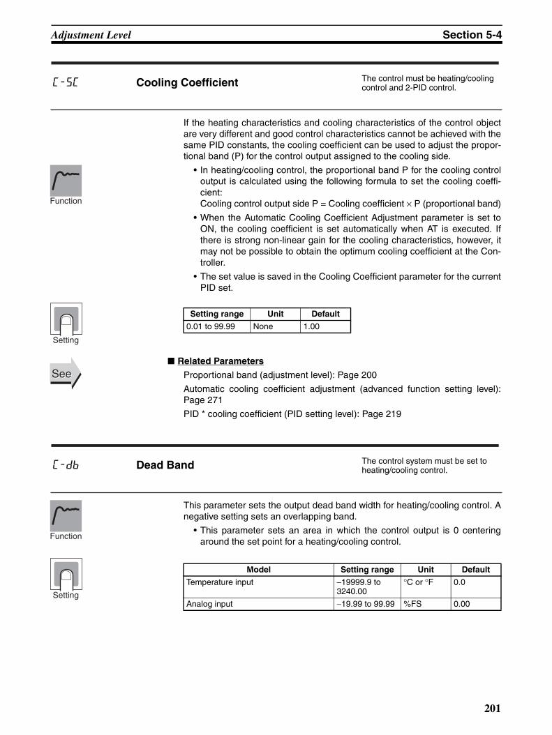
Adjustment Level Section 5-4
If the heating characteristics and cooling characteristics of the control objectare very different and good control characteristics cannot be achieved with thesame PID constants, the cooling coefficient can be used to adjust the propor-tional band (P) for the control output assigned to the cooling side.
• In heating/cooling control, the proportional band P for the cooling controloutput is calculated using the following formula to set the cooling coeffi-cient:Cooling control output side P = Cooling coefficient × P (proportional band)
• When the Automatic Cooling Coefficient Adjustment parameter is set toON, the cooling coefficient is set automatically when AT is executed. Ifthere is strong non-linear gain for the cooling characteristics, however, itmay not be possible to obtain the optimum cooling coefficient at the Con-troller.
• The set value is saved in the Cooling Coefficient parameter for the currentPID set.
Related Parameters
Proportional band (adjustment level): Page 200
Automatic cooling coefficient adjustment (advanced function setting level):Page 271
PID * cooling coefficient (PID setting level): Page 219
This parameter sets the output dead band width for heating/cooling control. Anegative setting sets an overlapping band.
• This parameter sets an area in which the control output is 0 centeringaround the set point for a heating/cooling control.
c-sc Cooling Coefficient The control must be heating/cooling control and 2-PID control.
Setting range Unit Default
0.01 to 99.99 None 1.00
Function
Setting
SeeSee
c-db Dead Band The control system must be set to heating/cooling control.
Model Setting range Unit Default
Temperature input −19999.9 to 3240.00
°C or °F 0.0
Analog input −19.99 to 99.99 %FS 0.00
Function
Setting
201

Adjustment Level Section 5-4
• This parameter sets the required manipulated variable to remove offsetduring stabilization of P or PD control.
Related Parameters
PID * integral time (PID setting level): Page 217
PID ON/OFF (initial setting level): Page 228
This parameter sets the hysteresis for ensuring stable operation at the ON/OFF switching point.
• For standard control, use the Hysteresis (Heating) parameter. The Hyster-esis (Cooling) parameter cannot be used.
• For heating/cooling control, the hysteresis can be set independently forheating/cooling. The Hysteresis (Heating) parameter is used for the heat-ing side, and the Hysteresis (Cooling) parameter is used for the coolingside.
Related Parameters
PID ON/OFF, Standard or heating/cooling (initial setting level): Page 228
of-r Manual Reset ValueThe control must be standard control and 2-PID control.The Integral Time parameter for PID sets 1 to 8 must be set to 0.
Setting range Unit Default
0.0 to 100.0 % 50.0
Function
Setting
SeeSee
hys Hysteresis (Heating) The control must be ON/OFF control. For the Hysteresis (Cooling) parame-ter, the control must be heating/cool-ing control.
chys Hysteresis (Cooling)
Function
Setting
Parameter name
Model Setting range Unit Default
Hysteresis (Heating)
Temperature input 0.1 to 3240.00 °C or °F 1.0
Analog Input 0.01 to 99.99 %FS 0.10
Hysteresis (Cooling)
Temperature input 0.1 to 3240.00 °C or °F 1.0
Analog Input 0.01 o 99.99 %FS 0.10
SeeSee
202

Adjustment Level Section 5-4
• This parameter sets the time for the control operation when using the sim-ple program function.
• The set value is saved in the Soak Time parameter for the current bank.
Related Parameters
Program start, Soak time remain (operation level): Page 184
Bank * wait band, Bank * soak time (Bank setting level): Page 215
Program pattern (initial setting level): Page 229
Soak time unit (advanced function setting level): Page 266
• This parameter sets the stable band within which the soak time is mea-sured for the simple program function.
• The set value is saved in the Soak Time parameter for the current bank.
Related Parameters
Program start, Soak time remain (operation level): Page 184
Bank * wait band, Bank * soak time (Bank setting level): Page 215
Program pattern (initial setting level): Page 229
Soak time unit (advanced function setting level): Page 266
soak Soak Time The Program Pattern parameter must not be set to OFF.
Setting range Unit Default
1 to 9999 min or h 1
Function
Setting
SeeSee
wt-b Wait Band The Program Pattern parameter must not be set to OFF.
Model Setting range Unit Default
Temperature input OFF or 0.1 to 3240.0
°C or °F off
Analog Input OFF or 0.01 to 99.99
%FS
Function
Setting
SeeSee
203

Adjustment Level Section 5-4
• This parameter sets the MV to use when the RUN/STOP status changesfrom RUN to STOP.
Related Parameters
RUN/STOP (operation level): Page 185
MV at stop and error addition (advanced function setting level): Page 256
• This parameter sets the MV to use when an input error occurs.
Related Parameters
MV at stop and error addition (advanced function setting level): Page 256
mv-s MV at StopThe control must be set to 2-PID control. The MV at Stop and Error Addition parameter must be ON.
Setting range Unit Default
Standard control: −5.0 to 105.0Heating/cooling control: −105.0 to 105.0Position-proportional control (close, with the Direct Setting of Position Proportional MV parameter ON): −5.0 to 105.0
% 0.0
Position-proportional control (floating or with the Direct Setting of Positional Propor-tional MV parameter OFF): CLOS, HOLD, OPEN
None HOLD
Function
Setting
SeeSee
mv-e MV at PV ErrorThe control must be set to 2-PID control. The MV at Stop and Error Addition parameter must be ON.
Setting range Unit Default
Standard control: −5.0 to 105.0Heating/cooling control: −105.0 to 105.0Position-proportional control (close, with the Direct Setting of Position Proportional MV parameter ON): −5.0 to 105.0
% 0.0
Position-proportional control (floating or with the Direct Setting of Positional Propor-tional MV parameter OFF): CLOS, HOLD, OPEN
None HOLD
Function
Setting
SeeSee
204

Adjustment Level Section 5-4
• This parameter sets the rate of change during SP ramp operation. Set themaximum permissible change width per unit of time as the SP ramp setvalue. The SP ramp function is disabled if this parameter is set to OFF.
• During temperature input, the decimal point position of the SP ramp setvalue is dependent on the currently selected sensor, and during analoginput it is dependent on scaling.
• The set value is saved in the SP Ramp Set Value parameter for the cur-rent bank.
Related Parameters
Input type: Page 224, Scaling upper limit, Scaling lower limit, Decimal point(initial setting level): Page 226, ST: Page 228 (initial setting level)
SP ramp time unit (advanced function setting level): Page 244
Bank * SP ramp set value (bank setting level): Page 211
• The MV Upper Limit and MV Lower Limit parameters set the upper andlower limits of the manipulated variable. When the calculated manipulatedvariable exceeds the upper or lower limit value, the upper or lower limitvalue will be the output level.
• The set value is saved in the MV Upper Limit and MV Lower Limit param-eters for the current PID set.
• MV Upper LimitThe setting ranges during standard control, heating/cooling control, andposition-proportional (close) control are different.
sprt SP Ramp Set Value The ST parameter must be set to OFF.
Setting range Unit Default
OFF or 1 to 32400 EU/s or EU/minute off
Function
Setting
SeeSee
ol-h MV Upper Limit The control must be set to 2-PID control. The ST parameter must be set to OFF. Position-proportional (close) control must be supported.
ol-l MV Lower Limit
Control method Setting range Unit Default
Standard MV lower limit + 0.1 to 105.0 % 105.0
Heating/cooling 0.0 to 105.0
Position proportional (close)
MV lower limit + 0.1 to 105.0
Function
Setting
205

Adjustment Level Section 5-4
• MV Lower LimitThe setting ranges during standard control, heating/cooling control, andposition-proportional (close) control are different. The manipulated vari-able for the cooling control output side during heating/cooling control isexpressed as a negative value.
Related Parameters
PID ON/OFF: Page 228, ST: Page 228 (initial setting level)
PID * MV upper limit, PID * MV lower limit (PID setting level): Page 217
• The MV Change Rate Limit parameter sets the maximum allowable varia-tion in the MV per second. If the change in the MV exceeds this setting,the MV will be changed by the MV change rate limit until the calculatedvalue is reached. If the limit is set to 0.0, this function will be disabled.
• The MV Change Rate Limit parameter will not operate in the following sit-uations.
• In manual mode
• During ST execution (Cannot be set when ST is ON.)
• During AT execution
• During ON/OFF control
• While stopped (MV output during STOP)
• During MV output when error occurs
Related Parameters
Proportional band (adjustment level): Page 200
Control method Setting range Unit Default
Standard −5.0 to MV upper limit −0.1 % −5.0
Heating/cooling −105.0 to 0.0 −105.0
Position proportional (close)
5.0 to MV upper limit −0.1 −5.0
SeeSee
orl MV Change Rate Limit 2-PID control must be used.
ST must be OFF.
Setting range Unit Default
0.0 to 100.0 %/s 0.0
Function
Setting
SeeSee
206

Adjustment Level Section 5-4
• This parameter sets the output hold interval (the ON/OFF switching inter-val between the open and close outputs) for position-proportional control.
Related Parameters
Open/close hysteresis (adjustment level): Page 207
• This parameter provides hysteresis in position-proportional control whenthe open and close outputs are switched ON or OFF.
Related Parameters
Position proportional dead band (adjustment level): Page 207
• This parameter sets the extraction of square root low-cut point used forthe inputs. The data after extracting the square root is shown below.
db Position Proportional Dead Band Position-proportional control must be supported.
Setting range Unit Default
Position proportional (close):0.1 to 10.0
% 4.0
Position proportional (floating): 0.1 to 10.0
% 2.0
Function
Setting
SeeSee
oc-h Open/Close Hysteresis Position-proportional control must be supported.
Setting range Unit Default
0.1 to 20.0 % 0.8
Function
Setting
SeeSee
sqrp Extraction of Square Root Low-cut PointThe input type must be an analog input, and the Extraction of Square Root Enable parameter must be set to ON.
Function
207

Adjustment Level Section 5-4
• The low-cut point is used for extracting the square root for flowrate sen-sors.
Related Parameters
Extraction of square root enable (initial setting level): Page 207
Setting range Unit Default
0.0 to 100.0 % 0.0
Argument 1 (input data)
Operation result100% FS
0
100% FS
Extraction of square root low-cut point
Setting
SeeSee
208

Bank Setting Level Section 5-5
5-5 Bank Setting LevelThe bank setting level is used to make settings such as the SP, PID set, alarmvalue, soak time, and wait band for each bank. Move to a particular bank fromthe Display Bank Selection parameter, which is displayed first in the bankselection level.
d.bnk2
M
M
M
M
M
M
M
M
M
M
M
M
M
M
M
M
M
M
M
M
M
M
M
M
M
M
M
M
M
0.lsp
0.0
0.pid1
0.spr
off
0.0
-10.a
1h
0.0
0.a
1l0.0
0.a
0.0
-20.a
2h
0.0
0.a
2l
0.0
0.a
0.0
-30.a
3h
0.0
0.a
3l
0.0
0.a
1
0.sok
off
0.wtb
2l
0.0
7.a
0.0
-37.a
3h0.0
7.a
3l0.0
7.a
1
7.sok
off
7.wtb
7.lsp
0.0
7.pid1
7.sproff
1h
0.0
7.a
1l0.0
7.a
0.0
-27.a
2h
0.0
7.a
d.bnk7
-17.a
0.0
d.bnk2
d.bnk1
d.bnk0
c
c
c
c
c
c
c
c
c
c
c
c
c
c
c
c
c
c
c
Power ON
Operation LevelAdjustment
Level
PID Setting Level
Bank Setting Level
Temperature control being performed.
Press the O Key for at least 1 s.
Bank Setting Level
Display Bank SelectionBank0
Bank1
Bank2
Bank7
Bank 7 SP
Bank 7 PID Set No.
Bank 7 SP Ramp Set Value
Bank 7 Alarm Value 1
Bank 7 Alarm Value Upper Limit 1
Bank 7 Alarm Value Lower Limit 1
Bank 7 Alarm Value 2
Bank 7 Alarm Value Upper Limit 2
Bank 7 Alarm Value Lower Limit 2
Bank 7 Alarm Value 3
Bank 7 Alarm Value Upper Limit 3
Bank 7 Alarm Value Lower Limit 3
Bank 7 Soak Time
Bank 7 Wait Band
209

Bank Setting Level Section 5-5
The parameter is used to select the bank for making the display settings.
• This parameter selects the bank number for which the display settings areto be made.
• Up to eight banks (0 to 7) can be used. The following items are registeredin each bank: SP, alarm value, SP ramp set value, soak time, and waitband.
Note The current bank will be displayed. If you use the U and D Keys tochange the bank number, the monitor function will be canceled.
Related Parameters
Bank No. (operation level): Page 179Bank numbers used (initial setting level): Page 237
These parameters are used to set the SP for each bank.
• The SP can be set for banks 0 to 7.
Related Parameters
PV/SP (operation level): Page 177
These parameters are used to set the PID set for each bank.
• The PID set can be set for banks 0 to 7.
• If the parameter is set to 0, the PID set that is automatically selected withthe PID set automatic selection function, based on the PV, DV, and SP, willbe used for control. To specify the PID set, set a number from 1 to 8.
d.bnk Display Bank Selection
Setting range Default
0 to 7 See note.
Function
Setting
SeeSee
*.lsp Bank (0 to 7) SP
Setting range Default
SP lower limit to SP upper limit 0.0FunctionSetting
SeeSee
*.pid Bank (0 to 7) PID Set No. 2-PID control must be used.
Setting range Default
0 to 8 1
Function
Setting
210

Bank Setting Level Section 5-5
Related Parameters
PID (*) proportional band, PID (*) integral time, PID (*) derivative time (PIDsetting level): Page 217PID (*) automatic selection range upper limit (PID setting level): Page 218PID set automatic selection data (advanced function setting level): Page 269
These parameters are used to set the SP ramp set value for each bank.
• The SP ramp set value can be set for banks 0 to 7.
• This parameter specifies the rate of change during SP ramp operation.Set the maximum allowable change width per unit of time as the SP rampset value. When this parameter set to OFF, the SP ramp function will bedisabled.
• During temperature input, the decimal point position for the SP ramp setvalue depends on the current sensor, and during analog input it dependson scaling.
Related Parameters
Input type: Page 224Scaling upper limit, Scaling lower limit, Decimal point: Page 226ST (initial setting level): Page 228SP ramp time unit (advanced function setting level): Page 244
These parameters set one of the input values "X" in the alarm type list foreach bank.
• These parameters set the value for alarm value 1 in banks 0 to 7.
• During temperature input, the decimal point position is set automaticallyaccording to the current sensor, and during analog input it depends on theDecimal Point parameter setting.
SeeSee
*.spr Bank 0 to 7 SP Ramp Set Value The ST parameter must be set to OFF.
Setting range Unit Default
OFF, 1 to 32400 EU/s, EU/min, EU/h OFF
Function
Setting
SeeSee
*.a-1 Bank * Alarm Value 1(*: 0 to 7)
Alarm 1 must be assigned.The alarm 1 type must not be 0, 1, 4, 5, or 12.
Setting range Unit Default
−19999 to 32400 EU 0.0
Function
Setting
211

Bank Setting Level Section 5-5
Related Parameters
Input type: Page 224Scaling upper limit, Scaling lower limit, Decimal point: Page 226Alarm 1 type (initial setting level): Page 231Standby sequence reset: Page 244Auxiliary output * open in alarm: Page 245Alarm 1 hysteresis: Page 233Alarm 1 latch (advanced function level): Page 250
These parameters set the alarm value upper and lower limits individually foreach bank when the mode for setting the upper and lower limits is selected forthe Alarm 1 Type parameter (initial setting level).
• These parameters set the upper and lower limits of alarm 1 for banks 0 to7.
• During temperature input, the decimal point position is set automaticallyaccording to the current sensor, and during analog input it depends on theDecimal Point parameter setting.
Related Parameters
Input type: Page 224Scaling upper limit, Scaling lower limit, Decimal point: Page 226Alarm 1 type (initial setting level): Page 231Standby sequence reset: Page 244Auxiliary output * open in alarm: Page 245Alarm 1 hysteresis: Page 233Alarm 1 latch (advanced function level): Page 250
These parameters set one of the input values "X" in the alarm type list foreach bank.
• These parameters set the value for alarm value 2 in banks 0 to 7.
• During temperature input, the decimal point position is set automaticallyaccording to the current sensor, and during analog input it depends on theDecimal Point parameter setting.
SeeSee
*.a1h Bank * Alarm Value Upper Limit 1
*.a1lBank * Alarm Value Lower Limit 1(*: 0 to 7)
Alarm 1 must be assigned.
The alarm 1 type must not be 1, 4, or 5.
Setting range Unit Default
−19999 to 32400 EU 0.0
Function
Setting
SeeSee
*.a-2 Bank * Alarm Value 2(*: 0 to 7)
Alarm 2 must be assigned.The alarm 2 type must not be 0, 1, 4, or 5, or 12.
Function
212

Bank Setting Level Section 5-5
Related Parameters
Input type: Page 224Scaling upper limit, Scaling lower limit, Decimal point: Page 226Alarm 2 type (initial setting level): Page 233Standby sequence reset: Page 244Auxiliary output * open in alarm: Page 245Alarm 2 hysteresis: Page 233Alarm 2 latch (advanced function level): Page 250
These parameters set the alarm value upper and lower limits individually foreach bank when the mode for setting the upper and lower limits is selected forthe Alarm 2 Type parameter (initial setting level).
• These parameters set the upper and lower limits of alarm 2 for banks 0 to7.
• During temperature input, the decimal point position is set automaticallyaccording to the current sensor, and during analog input it depends on theDecimal Point parameter setting.
Related Parameters
Input type: Page 224Scaling upper limit, Scaling lower limit, Decimal point: Page 226Alarm 2 type (initial setting level): Page 233Standby sequence reset: Page 244Auxiliary output * open in alarm: Page 245 Alarm 2 hysteresis: Page 233Alarm 2 latch (advanced function level): Page 250
These parameters set one of the input values "X" in the alarm type list foreach bank.
• These parameters set the value for alarm value 3 in banks 0 to 7.
Setting range Unit Default
−19999 to 32400 EU 0.0Setting
SeeSee
*.a2h Bank * Alarm Value Upper Limit 2
*.a2l Bank * Alarm Value Lower Limit 2(*: 0 to 7)
Alarm 2 must be assigned.The alarm 2 type must not be 1, 4, or 5.
Setting range Unit Default
−19999 to 32400 EU 0.0
Function
Setting
SeeSee
*.a-3 Bank * Alarm Value 3(*: 0 to 7)
Alarm 3 must be assigned.
The alarm 3 type must not be 0, 1, 4, 5, or 12.
Function
213

Bank Setting Level Section 5-5
• During temperature input, the decimal point position is set automaticallyaccording to the current sensor, and during analog input it depends on theDecimal Point parameter setting.
Related Parameters
Input type: Page 224Scaling upper limit, Scaling lower limit, Decimal point: Page 226Alarm 3 type (initial setting level): Page 234Standby sequence reset: Page 244Auxiliary output * open in alarm: Page 245Alarm 3 hysteresis: Page 233Alarm 3 latch (advanced function level): Page 250
These parameters set the alarm value upper and lower limits individually foreach bank when the mode for setting the upper and lower limits is selected forthe Alarm 3 Type parameter (initial setting level).
• These parameters set the upper and lower limits of alarm 3 for banks 0 to7.
• During temperature input, the decimal point position is set automaticallyaccording to the current sensor, and during analog input it depends on theDecimal Point parameter setting.
Related Parameters
Input type: Page 224Scaling upper limit, Scaling lower limit, Decimal point: Page 226Alarm 3 type (initial setting level): Page 234Standby sequence reset: Page 244Auxiliary output * open in alarm: Page 245Alarm 3 hysteresis: Page 233Alarm 3 latch (advanced function level): Page 250
Setting range Unit Default
−19999 to 32400 EU 0.0Setting
SeeSee
*.a3h Bank * Alarm Value Upper Limit 3 Alarm 3 must be assigned.
*.a3l Bank * Alarm Value Lower Limit 3(*: 0 to 7)
The alarm 3 type must be set to "upper and lower limit alarm," "upper and lower limit range alarm," or "upper and lower limit alarm with standby sequence."
Setting range Unit Default
−19999 to 32400 EU 0.0
Function
Setting
SeeSee
214

Bank Setting Level Section 5-5
These parameters set the soak time for each bank.
• These parameters set the time for the control operation in each bankwhen using the simple program function
• When the bank function is enabled, this parameter is enabled when thecurrent bank program pattern is not set to OFF.
Related Parameters
Program start, Soak time remain (operation level): Page 184Bank (*) wait band (bank setting level): Page 215Program pattern (initial setting level): Page 229Soak time unit (advanced function setting level): Page 266
These parameters set the wait band for each bank.
• These parameters set the stable band, in each bank, within which thesoak time is measured for the simple program function.
• When the bank function is enabled, this parameter is enabled when thecurrent bank program pattern is not set to OFF.
Related Parameters
Program start, Soak time remain (operation level): Page 184Bank (*) soak time (bank setting level): Page 215Program pattern (initial setting level): Page 229Soak time unit (advanced function setting level): Page 266
*.sok Bank Soak Time The Program Pattern parameter must not be set to OFF.
Setting range Unit Default
0 to 9999 min or h 1
Function
Setting
SeeSee
*.wtb Bank Wait Band The Program Pattern parameter must not be set to OFF.
Setting range Unit Default
Temperature: OFF, 0.1 to 3,240.0
°C or °F off
Analog: OFF, 0.01 to 99.99
%FS
Function
Setting
SeeSee
215

PID Setting Level Section 5-6
5-6 PID Setting LevelThe PID setting level is used to make settings such as PID values for eachPID set and MV limit values. Move to a particular PID set from the Display PIDSet Selection parameter, which is displayed first in the PID setting level.
This parameter is used to select the PID set for making the display settings.
• This parameter selects the PID set for which the display settings are to bemade.
• Up to eight sets (1 to 8) can be used. The following items registered ineach set: PID value, MV upper and lower limits, automatic selection rangeupper limit, cooling coefficient, and LBA detection time.
Note The current PID set will be displayed. If you use the U and D Keysto change the PID set, the monitor function will be canceled.
Related Parameters
Bank No. (operation level): Page 179
d.pid Display PID Selection
d.pid3
d.pid2
d.pid1
d.pid8
M
M
M
M
M
M
1.oll-5.0
M
M
M
M
M
M
M
M
M
8.p8.0
l-5.0
8.d40.0
h105.0
M
M
M
8.ol
8.ol
1.p8.0
1.i233.0
1.d40.0
1.olh105.0
1.aut
1320.0
1.csc1.00
1.lba0
8.i233.0
8.aut
1320.0
sc1.00
8.c
8.lba0
c
c
c
c
Power ON
Operation LevelAdjustment
Level
PID Setting Level
Bank Setting Level
Temperature control being performed.
Press the O Key for at least 1 s.
PID Setting Level
Display PID SelectionPID1
PID 8 Proportional Band
PID2
PID3
PID8
PID 8 Integral Time
PID 8 Derivative Time
PID 8 MV Upper Limit
PID 8 MV Lower Limit
PID 8 Automatic Selection Range Upper Limit
PID 8 Cooling Coefficient
PID 8 LBA Detection Time
Setting range Default
1 to 8 See note.
Function
Setting
SeeSee
216

PID Setting Level Section 5-6
These parameters set the PID constants for each PID set. When AT and STare executed, the parameters are set automatically.
Note If the settings for RT (robust tuning) are changed, the P (proportion-al band), I (integral time), and D (derivative time) will be initialized.
Related Parameters
AT execute/cancel (adjustment level): Page 192
These parameters set the MV upper and lower limits for each PID set.
• The MV Upper Limit and MV Lower Limit parameters set the upper andlower limits of the manipulated variable. When the calculated manipulatedvariable exceeds the upper or lower limit value, the upper or lower limitvalue will be the output level.
• MV limits do not operate when floating control is used with models thatsupport position-proportional control, so these parameters are disabled.
*.p PID * Proportional Band*.i PID * Integral Time 2-PID control must be used.
*.d PID * Derivative Time (*: 1 to 8)
P action: For the P action, the MV is proportional to the derivative.
I action: For the I action, an output is produced that is proportional to the time integral of the derivative. An offset normally occurs with the proportional action, so the proportional action is used in combination with the inte-gral action. As time passes, this offset disappears and the control tem-perature comes to match the set point.
D action: For the D action, an output is produced that is proportional to the time derivative of the input. Because the proportional action and integral action correct for errors in the control result, the control system will be slow to respond to sudden changes in temperature. The derivative action performs a corrective action by increasing the MV in proportion to the slope of the temperature change.
Parameter Setting range Unit Default
Proportional Band
Temperature: 0.1 to 3,240.0 °C or °F 8.0
Analog: 0.1 to 999.9 %FS 10.0
Integral Time Standard/heating and cooling, position proportional (closed): 0.0 to 3,240.0
s 233.0
Position proportional (floating): 0.1 to 3,240.0
Derivative Time 0.0 to 3240.0 s 40.0
Function
Setting
SeeSee
*.olh PID * MV Upper Limit 2-PID control must be used.The ST parameter must be set to OFF.
Closed control must be used (for position proportional models).
*.oll PID * MV Lower Limit(*: 1 to 8)
Function
217

PID Setting Level Section 5-6
• MV Upper LimitThe setting range depends on whether standard, position-proportional(closed) control, or heating/cooling control is used. In addition, the coolingMV during heating/cooling control is expressed as a negative value.
• MV Lower LimitThe setting range depends on whether standard, position-proportional(closed) control, or heating/cooling control is used. In addition, the coolingMV during heating/cooling control is expressed as a negative value.
Related Parameters
PID ON/OFF: Page 228ST (initial setting level): Page 228
These parameters set the upper limit for each PID set when PID sets areselected automatically.
• These parameters are used to set the automatic selection range upperlimits for PID sets 1 to 8.
• The sensor setting range for PID set 8 is 32,400 EU for temperatureinputs and 105.0% for analog inputs. This parameter does not need to beset.
• These values apply to the PV (process value), DV (deviation), or SP (setpoint) set in the PID Set Automatic Selection Data parameter. The defaultsetting is PV.
Related Parameters
PID set automatic selection data (advanced function setting level): Page 269
Control method Setting range Unit Default
Standard MV lower limit + 0.1 to 105.0 % 105.0
Heating/cooling 0.0 to 105.0
Position-propor-tional (closed)
MV lower limit + 0.1 to 105.0
Control method Setting range Unit Default
Standard −5.0 to MV lower limit - 0.1 % −5.0
Heating/cooling −105.0 to 0.0 −105.0
Position-propor-tional (closed)
−5.0 to MV upper limit - 0.1 −5.0
Setting
SeeSee
*.aut PID * Automatic Selection Range Upper Limit (*: 1 to 8)
2-PID control must be used.
Setting range Unit Default
Temperature: −19,999 to 32,400
EU 1320.0
Analog: −5.0 to 105.0 % 105.0
Function
Setting
SeeSee
218

PID Setting Level Section 5-6
If the heating and cooling characteristics of the control object are very differ-ent and good control characteristics cannot be achieved with the same PIDconstants, the cooling coefficient can be used to adjust the proportional band(P) for the control output assigned to the cooling side. One parameter is setfor each PID set.
• In heating/cooling control, the proportional band P for the cooling controloutput is calculated using the following formula to set the cooling coeffi-cient:Cooling control output side P = Cooling coefficient × P (proportional band)
• The cooling coefficient will be set automatically if autotuning is executedwhen the Automatic Cooling Coefficient Adjustment parameter is set toON. The execution results will be saved in the PID set where autotuningwas started. If non-linearity is strong in the cooling characteristics, how-ever, this function may not find the optimum cooling coefficient.
Related Parameters
PID (*) proportional band (PID setting level): Page 217
These parameters set whether the LBA function is to be enabled or disabledand sets the time interval for detection, for each PID set.
• These parameters set the time interval for detecting the LBA.
• Setting 0 disables the LBA function.
• For ON/OFF control, make the setting in the LBA Detection Time parame-ter in the advanced function setting level.
Related Parameters
Alarm 1 type (initial setting level): Page 231LBA level (advanced function setting level): Page 259LBA band (advanced function setting level): Page 260
*.csc PID * Cooling Coefficient(*: 1 to 8)
Heating and cooling control and 2-PID control must be used.
Setting range Unit Default
0.01 to 99.99 None 1.00
Function
Setting
SeeSee
*.lba PID * LBA Detection Time(*: 1 to 8)
2-PID control must be used.
Alarm 1 must be assigned.
The alarm 1 type must be 12 (LBA).
Setting range Unit Default
0 to 9999 s 0
Function
Setting
SeeSee
219

Monitor/Setting Item Level Section 5-7
5-7 Monitor/Setting Item LevelMonitor/setting items can be displayed by means of the function key when thePF Setting parameter (advanced function setting level) is set to PFDP: Moni-tor/Setting Item (for the E5AN/EN-H only).
• When the PF Key is set to display monitor/setting items, pressing the PFKey will display in order the contents of the Monitor/Setting Item 1 to 5parameters. The contents of these parameters are shown in the followingtable. For the setting (monitor) ranges, refer to the applicable parameters.
Related Parameters
PF setting (advanced function setting level): Page 273
Monitor/setting items 1 to 5 (advanced function setting level): Page 274
Operation Level
Power ON
PF Key
PF
Adjustment Level
Monitor/Setting Item Level
Control in progress
Press the O Key for at least 1 s.
Key
PID Setting Level
Bank Setting Level
Monitor/Setting Item Display 1 to 5The PF Setting parameter must be set to PFDP, and the Monitor/Setting Item 1 to 5 parameters must not be set to OFF.
Set value
Setting Remarks
Monitor/Setting Symbol
0 Disabled ---
1 PV/SP/Bank No. Can be set. (SP) ---
2 PV/SP/MV Can be set. (SP) ---
3 PV/SP /Soak time remain Can be set. (SP) ---
4 Proportional band (P) Can be set. p
5 Integral time (I) Can be set. i
6 Derivative time (D) Can be set. d
7 Alarm value 1 Can be set. al-1
8 Alarm value upper limit 1 Can be set. al1h
9 Alarm value lower limit 1 Can be set. al1l
10 Alarm value 2 Can be set. al-2
11 Alarm value upper limit 2 Can be set. al2h
12 Alarm value lower limit 2 Can be set. al2l
13 Alarm value 3 Can be set. al-3
14 Alarm value upper limit 3 Can be set. al3h
15 Alarm value lower limit 3 Can be set. al3l
16 Bank No. Can be set. bank
Function
SeeSee
220

Manual Control Level Section 5-8
5-8 Manual Control LevelThe manipulated variable can be set in manual mode while the PV/MV param-eter is displayed.
The final MV used in automatic mode will be used as the initial manual MVwhen moving from automatic mode to manual mode. In manual mode, thechange value will be saved immediately and reflected in the actual MV.
To move from the operation level to the manual control level, press the O Keyfor at least three seconds with the Auto/Manual Switch parameter displayed.In addition, this operation can be performed using the PF Key by setting thePF Key parameter (advanced function setting level) to A-M (Auto/Manual). Fordetails on the setting method, refer to 4-13 Performing Manual Control.
This setting cannot be made during ON/OFF operation.
• The MANU indicator will light during manual control.
• It is not possible to move to any displays except for the PV/MV parameterduring manual operation.
• To return to the operation level, press the O Key or the PF Key in themanual control level for at least one second.
The manual control level display appears as shown below.
Press the O Key for at least 1 s; display will flash.
a-m PF
Operation Level
Power ON
Adjustment Level
Press the O Key for at least 1 s.
Press the Key for at least 1 s. (See note.)
Manual Control Level
PF
Press the O Key for at least 3 s.
Press the Key for at least 1 s or the O Key for at least 1 s. (See note.)
Note: When the PF Setting parameter is set to A-M for a Controller that has a PF Key (E5AN/EN-H).
PID Setting Level
Bank Setting Level
PV/MV (Manual MV)
Function 25.0100.0
50.0
25.050.0
MANU MANU
25.0MANU 50.0
With No. 3 Display Without No. 3 Display
PV/SP/Manual MV PV/Manual MVPV/Manual MV
Note: When the PV/SP Display Screen Selection parameter is 0.
C CC
221

Manual Control Level Section 5-8
Note When the Manual MV Limit Enable parameter is set to ON, the setting rangewill be the MV lower limit to the MV upper limit.
Related Parameters
Standard or heating/cooling (initial setting level): Page 228
Monitor range Unit
Process value Temperature: According to indication range for each sensor.
Analog: Scaling lower limit −5% FS to Scaling upper limit +5% FS (Refer to page 335.)
EU
Set point SP lower limit to SP upper limit EU
Setting range Unit
MV (manual MV) Standard control −5.0 to 105.0 (See note.)
%
Heating/cooling control −105.0 to 105.0 (See note.)
Position-proportional control −5.0 to 105.0 (See note.)
SeeSee
222

Initial Setting Level Section 5-9
5-9 Initial Setting LevelThis level is used to set up the basic Digital Controller specifications. In thislevel, you can set the Input Type parameter to set the sensor input to be con-nected, limit the setting range of set points, set the alarm modes, and performother operations.
To move from the operation level to the initial setting level, press the O Keyfor at least three seconds with any parameter displayed except for the Auto/Manual Switch parameter.
• The initial setting level is not displayed when the Initial/CommunicationsProtect parameter is set to 2. It can be used when the Initial/Communica-tions Protect parameter is set to 0 or 1.
• If the Input Type parameter is set for an analog input, the following param-eters will be set: Scaling upper limit, Scaling lower limit, and Decimalpoint.
Operation Level
Initial Setting Level
Control stops.
Power ON
Control in progress
Control stopped
25100
C
Press the O Key for at least 1 s.
Press the O Key for at least 1 s; display will flash.
Press the O Key for at least 3 s.
223

Initial Setting Level Section 5-9
• This parameter sets the type of sensor.
• When this parameter is changed, the set point limiter is changed to thedefaults. If the limiter must be specified, set the SP Upper Limit and SPLower Limit parameters (initial setting level) again.
Initial Setting Level
M
M
M
M
M
M
M
M
M
M
M
M
M
M
M
M
M
M
M
MM
M
M
M
in-t
5
in-h100
in-l
0
dp0
d-uc
sl-h
1300.0
c
sl-l
-200.0
c
cntl
pid
s-hc
stnd
st
on
ptrn
off
cp
20
c-cp20
alt12
alt2
2
alt32
tr-t
off
tr-h
100.0
tr-l
0.0
o1-t
4-20
clfl
flot
calb
off
mot
30
off
sqr
amov
0
M
M
pbnk
7
M
alh1
0.2
c
M
alh2
0.2
c
M
alh3
0.2
c
M
M
M
M
ev-1none
ev-2stop
ev-3none
ev-4
none
M
ev-b
1
M
orev
or-r
ST (Self-tuning)
Input Type
Scaling Upper Limit
Scaling Lower Limit
Decimal Point
For input type of analog
Temperature Unit °C, °F
SP Upper Limit
SP Lower Limit
PID ON/OFF
Standard or Heating/Cooling
Program Pattern
Control Period (Heating)
Control Period (Cooling)
Set the ON/OFF output cycle.
Direct/Reverse Operation
Alarm 1 Type
Alarm 1
Hysteresis
Alarm 2 Type
Alarm 3 Type
Alarm 2
Hysteresis
Alarm 3
Hysteresis
Transfer Output Type
Linear output
Transfer Output Upper Limit
Transfer Output Lower Limit
Linear Current Output
Bank Numbers Used
Event Input 1 Assignment
Event Input 2 Assignment
Event Input 3 Assignment
Event Input 4 Assignment
Extraction of Square Root Enable
Valid Program Bank
Closed/Floating
Motor Calibration
Travel Time
Page Page Page
For input type of temperature
Limit the set point
For input type of temperature, stand-ard control, or PID
When assigning PID or control output to ON/OFF output
Linear output
Move to Advanced Func-tion Setting Level:Displayed when initial set-ting/ communications pro-tect is set to 0.
Move by setting password (−169).
224
226
226
226
226
227
227
228
228
228
229
230
230
233
233
233
234
235
236
236
236
237
241
240
240
240
239
238
238
238
238
230
231
231
233
in-t Input Type
Function
224

Initial Setting Level Section 5-9
• Set one of the set values from the following table. The default is 5.
• If a platinum resistance thermometer is mistakenly connected while a set-ting for other than a platinum resistance thermometer is in effect, S.ERRwill be displayed. To clear the S.ERR display, check the wiring and thencycle the power.
Related Parameters
Temperature unit, Set point upper limit, Set point lower limit (initial settinglevel): Page 226
Setting
Input type Specifications Set value Input temperature range
Platinum resistance thermometer
Pt100 0 −200.0 to 850.0 (°C)/−300.0 to 1,500.0 (°F)
1 −199.9 to 500.0 (°C)/−199.9 to 900.0 (°F)
2 0.0 to 100.0 (°C)/0.0 to 210.0 (°F)
JPt100 3 −199.9 to 500.0 (°C)/−199.9 to 900.0 (°F)
4 0.0 to 100.0 (°C)/0.0 to 210.0 (°F)
Thermocouple K 5 −200.0 to 1,300.0 (°C)/−300.0 to 2,300.0 (°F)
6 −20.0 to 500.0 (°C)/0.0 to 900.0 (°F)
J 7 −100.0 to 850.0 (°C)/−100.0 to 1,500.0 (°F)
8 −20.0 to 400.0 (°C)/0.0 to 750.0 (°F)
T 9 −200.0 to 400.0 (°C)/−300.0 to 700.0 (°F)
10 −199.9 to 400.0 (°C)/−199.9 to 700.0 (°F)
E 11 −200.0 to 600.0 (°C)/−300.0 to 1,100.0 (°F)
L 12 −100.0 to 850.0 (°C)/−100.0 to 1,500.0 (°F)
U 13 −200.0 to 400.0 (°C)/−300.0 to 700.0 (°F)
14 −199.9 to 400.0 (°C)/−199.9 to 700.0 (°F)
N 15 −200.0 to 1,300.0 (°C)/−300.0 to 2,300.0 (°F)
R 16 0.0 to 1,700.0 (°C)/0.0 to 3,000.0 (°F)
S 17 0.0 to 1,700.0 (°C)/0.0 to 3,000.0 (°F)
B 18 100.0 to 1,800.0 (°C)/300.0 to 3,200.0 (°F)
W 19 0.0 to 2,300.0 (°C)/0.0 to 3,200.0 (°F)
PLII 20 0.0 to 1,300.0 (°C)/0.0 to 2,300.0 (°F)
K 21 −50.0 to 200.0 (°C)/−50.0 to 200.0 (°F)
J 22 −50.0 to 200.0 (°C)/−50.0 to 200.0 (°F)
T 23 −50.0 to 200.0 (°C)/−50.0 to 200.0 (°F)
Platinum resistance thermometer
Pt100 24 −50.0 to 200.0 (°C)/−50.0 to 200.0 (°F)
Current input 4 to 20 mA 25 One of the following ranges depending on the scal-ing.−19999 to 32400−1999.9 to 3240.0−199.99 to 324.00−19.999 to 32.400
0 to 20 mA 26
Voltage input 1 to 5 V 27
0 to 5 V 28
0 to 10 V 29
SeeSee
225

Initial Setting Level Section 5-9
• These parameters can be used when the input type is set for an analoginput.
• When an analog input is used, scaling is performed. Set the upper limit inthe Scaling Upper Limit parameter and the lower limit in the Scaling LowerLimit parameter.
• The Decimal Point parameter specifies the decimal point position ofparameters (set point, etc.) whose unit is EU.
• Scaling Upper Limit, Scaling Lower Limit
• Decimal Point
Related Parameters
Input type (initial setting level): Page 224
• Set the temperature input unit to either °C or °F.
Related Parameters
Input type (initial setting level): Page 224
in-h Scaling Upper Limit The input type must be set for an analog input.
in-l Scaling Lower limitdp Decimal Point
Parameter name Setting range Unit Default
Scaling Upper Limit Scaling lower limit + 1 to 32400 None 100
Scaling Lower Limit −19999 to scaling upper limit − 1 None 0
Parameter name Setting range Default
Decimal Point 0 to 3 0
Set value Settings Example
0 0 digits past decimal point 12345
1 1 digits past decimal point 1234.5
2 2 digits past decimal point 123.45
3 3 digits past decimal point 12.345
Function
Setting
SeeSee
d-u Temperature Unit The input type must be set for a tem-perature input.
Setting range Default
c: °C, f: °F c
Function
Setting
SeeSee
226

Initial Setting Level Section 5-9
• These parameters set the upper and lower limits of the set points. A setpoint can be set within the range defined by the upper and lower limit setvalues in the SP Upper Limit and SP Lower Limit parameters. If theseparameters are reset, any set point that is outside of the new range will beforcibly changed to either the upper limit or the lower limit.
• When the temperature input type and temperature unit have beenchanged, the set point upper limit and set point lower limit are forciblychanged to the upper and lower limits of the sensor.
• During temperature input, the decimal point position depends on the cur-rently selected sensor, and during analog input it depends on the DecimalPoint parameter setting.
Controllers with Thermocouple/Resistance Thermometer Universal Inputs
Related Parameters
Input type: Page 224, Temperature unit: Page 226 (initial setting level)
sl-h SP Upper Limit sl-l SP Lower Limit
Parameter name
Setting range Unit Default
Set Point Upper Limit
Temperature SP lower limit + 1 to Input set-ting range upper limit
EU 1300.0
Analog SP lower limit + 1 to scaling upper limit
EU
Set Point Lower Limit
Temperature Input setting range lower limit to SP upper limit − 1
EU −200.0
Analog Scaling lower limit to SP upper limit − 1
EU
Function
Setting
SeeSee
227

Initial Setting Level Section 5-9
• This parameter selects 2-PID control or ON/OFF control.
• The auto-tuning and self-tuning functions can be used in 2-PID control.
Related Parameters
AT execute/cancel: Page 192, Manual reset, Hysteresis (heating), and Hyster-esis (cooling): Page 202 (adjustment level)
ST stable range (advanced function setting level): Page 247
• This parameter selects standard control or heating/cooling control.
• When heating/cooling control is selected for the E5CN-H (for a modelwhich does not support control output 2), the auxiliary output 2 terminal(SUB2) is assigned as the control output (cooling).
Related Parameters
MV monitor (heating): Page 188, MV monitor (cooling): Page 189 (operationlevel)
Cooling coefficient, Dead band: Page 201, Hysteresis (heating), Hysteresis(cooling): Page 202 (adjustment level)
Control period (heat), Control period (cool) (initial setting level): Page 230
Control output 1 assignment: Page 261, Control output 2 assignment, Auxil-iary output 1 assignment: Page 263, Auxiliary output 2 assignment: Page 264,Auxiliary output 3 assignment: Page 265 (advanced function setting level)
• The ST (self-tuning) function executes tuning from the start of programexecution to calculate PID constants matched to the control target. Whenthe ST function is in operation, be sure to turn ON the power supply of theload connected to the control output simultaneously with or before startingController operation.
cntl PID ON/OFF
Setting range Default
pid: 2-PID, onof: ON/OFF pid
Function
Setting
SeeSee
s-hc Standard or Heating/Cooling
Setting range Default
stnd: Standard, h-c: Heating/cooling stnd
Function
Setting
SeeSee
st ST (self-tuning)The control must be set to a temper-ature input, standard control, and 2-PID control.
Function
228

Initial Setting Level Section 5-9
• Auto-tuning can be started during self-tuning.
Related Parameters
Input type: Page 224, PID ON/OFF: Page 228 (initial setting level), ST stablerange (advanced function setting level): Page 247
This parameter sets the type of control when using the simple program func-tion.
• If the Program Pattern parameter is set to OFF, the simple program willnot operate.
• If the Program Pattern parameter is set to STOP, the RUN/STOP statuswill change to STOP after execution has been completed up to the banknumber specified in the Valid Program Bank parameter.
• If the Program Pattern parameter is set to CONT, control will continue inRUN status after execution has been completed up to the bank numberspecified in the Valid Program Bank parameter.
• If the Program Pattern parameter is set to LOOP, the program will returnto bank number 0 and repeat the program operation.
Related Parameters
Program start, Soak time remain: Page 184, RUN/STOP: Page 185 (operationlevel)
Bank * soak time, Bank * wait band (bank setting level): Page 215
Soak time unit (advanced function setting level): Page 266
Parameter name Setting range Unit Default
ST off: ST function OFF, on: ST function ON
None on
Setting
SeeSee
ptrn Program Pattern
Setting range Default
off Simple program function turned OFF off
stop Go to STOP mode at end of program.
cont Continue in RUN mode at end of program.
loop Return to bank number 0 and repeat the program operation.
Function
Setting
SeeSee
229

Initial Setting Level Section 5-9
• This parameter sets the final bank number for executing program opera-tion.
Related Parameters
Program pattern (initial setting level): Page 229
• These parameters set the output periods. Set the control periods takingthe control characteristics and the electrical durability of the relay intoconsideration.
• For standard control, use the Control Period (Heating) parameter. TheControl Period (Cooling) parameter cannot be used.
• When the heating control output is a current output, the Control Period(Heating) parameter cannot be used.
• For heating/cooling control, the control period can be set independentlyfor heating and cooling. The Control Period (Heating) parameter is usedfor the heating control output, and the Control Period (Cooling) parameteris used for the cooling control output
Related Parameters
PID ON/OFF (initial setting level): Page 228
pbnk Valid Program Bank
The Program Pattern parameter must not be set to OFF.
Setting range Default
0 to 7 7
Function
Setting
SeeSee
cp Control Period (Heating)
The cooling control output and heat-ing control outputs must be assigned to relay outputs, voltage outputs (for driving SSR), or SSR outputs.
The control must be set to 2-PID control.For the Control Period (Cooling) parameter, the control must be set to heating/cooling control.
c-cp Control Period (Cooling)
Parameter name Setting range Unit Default
Control Period (Heating) 0.5 or 1 to 99 Second 20
Control Period (Cooling) 0.5 or 1 to 99 Second 20
Function
Setting
SeeSee
230

Initial Setting Level Section 5-9
• “Direct operation” refers to control where the manipulated variable isincreased when the process value increases. Alternatively, “reverse oper-ation” refers to control where the manipulated variable is increased whenthe process value decreases.
• Select one of the following six alarm 1 types: Deviation, deviation range,absolute value, LBA, PV change rate alarm, or RSP alarm.
orev Direct/Reverse Operation
Setting range Default
or-r: Reverse operation, or-d: Direct operation or-r
Function
Setting
alt1 Alarm 1 Type Alarm 1 must be assigned.
Set values Alarm type Alarm output operation
When alarm value X is positive
When alarm value X is negative
0 Alarm function OFF Output OFF
1 (See note 1.)
Upper- and lower-limit (See note 2.)
2 Upper-limit
3 Lower-limit
4 (See note 1.)
Upper- and lower-limit range
(See note 3.)
5 (See note 1.)
Upper- and lower-limit with standby sequence
(See note 4.)
6 Upper-limit with standby sequence
7 Lower-limit with standby sequence
8 Absolute-value upper-limit
Function
SettingL H
ONOFF
SP
XONOFF
SP
ONOFF
SP
X
XONOFF
SP
XONOFF
SP
L HONOFF
SP
L HONOFF
SP(See note 5.)
XONOFF
SP
ONOFF
SP
X
XONOFF
SP
XONOFF
SP
XONOFF
0
XONOFF
0
231

Initial Setting Level Section 5-9
Note (1) With set values 1, 4 and 5, the upper- and lower- limit values can be setindependently for each alarm type, and are expressed as “L” and “H.”
(2) Set value: 1 (Upper- and lower-limit alarm)
(3) Set value: 4 (Lower limit range)
(4) Set value: 5 (Upper- and lower-limit with standby sequence)
• For the lower-limit alarms in cases 1 and 2 above, the alarm is normal-ly OFF if upper- and lower-limit hysteresis overlaps.
• In case 3, the alarm is always OFF.
(5) Set value: 5 (The alarm is always OFF if upper- and lower-limit alarm hys-teresis with standby sequence overlaps.)
(6) Displayed when remote SP input is supported.
• Set the alarm type independently for each alarm in the Alarm 1 to 3 Typeparameters in the initial setting level. The default is 2 (Upper-limit alarm).
Related Parameters
Bank * alarm value upper limit 1, Bank * alarm value lower limit 1 (bank settinglevel): Page 212
Standby sequence reset: Page 244, Auxiliary output 1 open in alarm: Page245, Alarm 1 hysteresis: Page 233, Alarm 1 latch: Page 250 (advanced func-tion setting level)
9 Absolute-value lower-limit
10 Absolute-value upper-limit with standby sequence
11 Absolute-value lower-limit with standby sequence
12 LBA (alarm 1 type only) ---
13 PV change rate alarm ---
14 Remote SP absolute value upper limit (See note 6.)
15 Remote SP absolute value lower limit (See note 6.)
Set values Alarm type Alarm output operation
When alarm value X is positive
When alarm value X is negative
ONOFF
X
0
ONOFF
X
0
XONOFF
0
XONOFF
0
ONOFF
X
0
ONOFF
X
0
XONOFF
0
XONOFF
0
ONOFF
X
0
ONOFF
X
0
L H
H < 0, L > 0|H| < |L|
SP L H
H > 0, L < 0|H| > |L|
SP LHH < 0, L < 0
SP
LHH < 0, L > 0
|H| ≥ |L|SP
LHH > 0, L < 0
|H| ≤ |L|SP
Case 3 (Always ON)Case 2Case 1
L H
H < 0, L > 0|H| < |L|
SP HL
H > 0, L < 0|H| > |L|
SP LHH < 0, L < 0
SP
L
L
H
H
H < 0, L > 0|H| ≥ |L|SP
SP
H > 0, L < 0|H| ≤ |L|
Case 3 (Always OFF)Case 2Case 1
SeeSee
232

Initial Setting Level Section 5-9
• These parameters set the hysteresis for alarms 1, 2, and 3.
Related Parameters
Bank * alarm value 1 to 3: Page 211, 212, 213, Bank * alarm value upper limit1 to 3, Bank * alarm value lower limit 1 to 3: (bank setting level): Page 212,213, 214
Alarm 1 to 3 type (initial setting level): Page 231, 233, 234
Standby sequence reset: Page 244, Alarm 1 to 3 open in alarm: Page 250,Alarm 1 to 3 latch: Page 250 (advanced function setting level)
• Select one of the following five alarm 2 types: Deviation, deviation range,absolute value, PV change rate alarm, or RSP alarm.
Refer to the alarm 1 type list. The 12: LBA (Loop Burnout Alarm) setting inthat list cannot be used.
Related Parameters
Bank * alarm value 2: Page 212
Bank * alarm value upper limit 2, Bank * alarm value lower limit 2 (bank settinglevel): Page 213
Standby sequence reset: Page 244, Auxiliary output 2 open in alarm: Page245, Alarm 2 hysteresis: Page 233
Alarm 2 latch (advanced function setting level): Page 250
alh1 Alarm 1 Hysteresis Alarm 1 must be assigned.
The alarm 1 type must not be 0, 12, or 13.
alh2 Alarm 2 HysteresisAlarm 2 must be assigned.
The alarm 2 type must not be 0, 12, or 13.
alh3 Alarm 3 HysteresisAlarm 3 must be assigned.The alarm 3 type must not be 0, 12, or 13.
Models Unit Default
Temperature input: 0.1 to 3,240.0
°C or °F 0.2
Analog input: 0.01 to 99.9 %FS 0.02
Function
Setting
SeeSee
alt2 Alarm 2 Type Alarm 2 must be assigned.
Function
Setting
SeeSee
233

Initial Setting Level Section 5-9
• Select one of the following five alarm 3 types:Deviation, deviation range, absolute value, PV change rate alarm, or RSPalarm.
Refer to the alarm 1 type list. The 12: LBA (Loop Burnout Alarm) setting inthat list cannot be used.
Related Parameters
Bank * alarm value 3: Page 213, Bank * alarm value upper limit 3, Bank *alarm value lower limit 3: Page 214 (operation level)
Standby sequence reset: Page 244, Auxiliary output * open in alarm: Page245, Alarm 3 hysteresis: Page 233, Alarm 3 latch: Page 250 (advanced func-tion setting level)
alt3 Alarm 3 Type Alarm 3 must be assigned.
Setting
SeeSee
234

Initial Setting Level Section 5-9
• This parameter sets the transfer output type.
• The following table shows the differences between models with a transferoutput and models without a transfer output that use control output 1 orcontrol output 2 as a simple transfer output.
Transfer Output Destination
Precision and User Calibration
Note For details on the calibration method, refer to SECTION 6 CALI-BRATION.
]
Related Parameter
Transfer output upper limit, Transfer output lower limit (initial setting level):Page 236
tr-t Transfer Output Type There must be a transfer output, cur-rent output, or linear voltage output.
Transfer output
Control output 1 Control output 2 Transfer output destination
Yes --- --- Transfer output
No Current output or linear voltage out-put
No
Relay output, voltage output (for driving SSR), or SSR output
Control output 1
No Current output or linear voltage out-put
Current output or linear voltage output
Control output 1
No Relay output, volt-age output (for driving SSR), or SSR output
Current output or linear voltage output
Control output 2
No Relay output, volt-age output (for driving SSR), or SSR output
No
Relay output, voltage output (for driving SSR), or SSR output
No
Precision User calibration
Transfer output ±0.3% FS Supported. (See note.)
Simple transfer output Not specified. Not supported.
Transfer output type Default
OFF off off
Set point sp
Set point during SP ramp sp-m
PV pv
MV monitor (heating) mv
MV monitor (cooling) c-mv
Valve opening v-m
Setting
SeeSee
235

Initial Setting Level Section 5-9
• This parameter sets the upper and lower limit values of transfer outputs.
Note (1) If the set point is selected, the remote SP will be output as long as theRemote SP Mode is selected in the SP Mode parameter.
(2) This setting will be ignored for position-proportional model.
(3) This setting will be ignored for standard control or position-proportionalcontrol.
(4) This parameter will be displayed only when the is a potentiometer inputfor a position-proportional model.
Related Parameter
Transfer output type (initial setting level): Page 235
This parameter selects the output type for linear current outputs.
• When control output 1 or control output 2 is a current output, select either4 to 20 mA or 0 to 20 mA as the output type.
tr-h Transfer Output Upper Limit A transfer output or linear voltage output must be supported.The Transfer Output Type parameter must not be set to OFF.
tr-l Transfer Output Lower Limit
Function
Setting
Transfer output type
Setting range Default Unit
Transfer output lower
limit
Transfer output upper
limit
Set point (See note 1.)
SP lower limit to SP upper limit SP lower limit SP upper limit EU
Set point during SP ramp
SP lower limit to SP upper limit
PV Temperature Input setting range lower limit to input setting range upper limit
Input setting range lower limit
Input setting range upper limit
Analog Analog scaling lower limit to analog scaling upper limit
Scaling lower limit
Scaling upper limit
MV monitor (heating) (See note 2.)
Standard −5.0 to 105.0 0.0 100.0 %
Heating/cooling
0.0 to 105.0
MV monitor (cooling) (See note 3.)
0.0 to 105.0
Valve opening (See note 4.)
Position-pro-portional
−10.0 to 110.0
SeeSee
o1-t Linear Current OutputThe E5CN-H must be used, and the control output must be a current out-put.
236

Initial Setting Level Section 5-9
Note Even when control output 1 or control output 2 is used as a control output or asimple transfer output, 0 to 20 mA can be used.
Related Parameter
Transfer output type (initial setting level): Page 235
The Bank Numbers Used parameter is used when switching bank numbersaccording to ON/OFF combinations of event inputs that have been preset forbank numbers 0 to 7. The number of banks used can be changed to 2, 4, or 8,according to the set value.
The Event Input Assignment Screen will not be displayed when event inputsare assigned for the Bank Numbers Used parameter. The following tablesshow the set values and the display/hide status of Event Input Assignments 1and 2.
Controllers with Event Inputs 1 and 2 (Two Event Inputs)
Controllers with Event Inputs 3 and 4 (Two Event Inputs)
Controllers with Event Inputs 1 to 4 (Four Event Inputs)
Linear current output
Default
4-20: 4 to 20 mA 0-20: 0 to 20 mA
4-20Setting
SeeSee
ev-b Bank Numbers Used Event inputs must be supported.
Function
Event Input Assignment 1 Event Input Assignment 2
Bank Num-bers Used
0 Displayed (Banks not switched.)
1 Hidden (2 banks) Displayed (Event input 2 not used to switch banks.)
2 Hidden (4 banks)
Event Input Assignment 3 Event Input Assignment 4
Bank Num-bers Used
0 Displayed (Banks not switched.)
1 Hidden (2 banks) Displayed (Event input 4 not used to switch banks.)
2 Hidden (4 banks)
Event Input Assignment
1
Event Input Assignment
2
Event Input Assignment
3
Event Input Assignment
4
Bank Numbers Used
0 Displayed (Banks not switched.)
1 Hidden (2 banks)
Displayed (Event inputs 2 to 4 not used to switch banks.)
2 Hidden (4 banks) Displayed (Event inputs 3 to 4 not used to switch banks.)
3 Hidden (8 banks) Displayed (Event input 4 not used to switch banks.)
237

Initial Setting Level Section 5-9
For details on event input assignments, refer to Event Input Assignments 1 to4 on page 238.
The following table shows the relationship between event input ON/OFF com-binations and the banks that are selected.
Note (1) For Controllers with event inputs 3 and 4, this becomes event input 3.
(2) For Controllers with event inputs 3 and 4, this becomes event input 4.
(3) Turn event inputs ON and OFF while power is being supplied. Changesin ON/OFF status are detected for inputs of 50 ms or longer. (For logicoperations, however they are detected at 250 ms or longer.)
Related Parameter
Event Input Assignment 1 to 4: Page 238
• The following functions can be assigned to event inputs 1 to 4.
RUN/STOP
Auto/Manual Switch
Program Start
Invert Direct/Reverse Operation
SP Mode Switch
100% AT Execute/Cancel
40% AT Execute/Cancel
Setting Change Enable/Disable
Communications Write Enable/Disable
Alarm Latch Cancel
Bank Numbers
Used
Event No. Bank No.
0 1 2 3 4 5 6 7
1 Event input 1 (See note 1.)
OFF ON --- --- --- --- --- ---
2 Event input 1 (See note 1.)
OFF ON OFF ON --- --- --- ---
Event input 2 (See note 2.)
OFF OFF ON ON --- --- --- ---
3 Event input 1 (See note 1.)
OFF ON OFF ON OFF ON OFF ON
Event input 2 (See note 2.)
OFF OFF ON ON OFF OFF ON ON
Event input 3 (See note 3.)
OFF OFF OFF OFF ON ON ON ON
Setting range Default
0 to 2 (for 2 event inputs)
0 to 3 (for 4 event inputs)
1
SeeSee
ev-* Event Input Assignment * (*: 1 to 4)An event input must be assigned.The event inputs must not be used to switch banks.
Function
238

Initial Setting Level Section 5-9
• Default: Event Input Assignment 1: none
Event Input Assignment 2: stop (For Controllers supporting event inputs 3 and 4, the default is none.)
Event Input Assignment 3: none
Event Input Assignment 4: none
Note (1) PRST (Program Start) can be set even when the Program Pattern param-eter is set to OFF, but the function will be disabled.
(2) This can be selected only for models that support the remote SP function.
(3) This setting will be ignored for heating/cooling control or for position-pro-portional (floating) control.
(4) This can be selected only for models that support communications. Also,when a work bit is selected as event input data, communications writingenable/disable cannot be selected.
Related Parameter
Bank Numbers Used (initial setting level): Page 237
• This parameter is used to select the control method for position-propor-tional control.
Setting Function
none None
stop RUN/STOP
manu Auto/Manual
prst Program start (See note 1.)
drs Invert Direct/Reverse Opera-tion
rsp SP Mode Switch (See note 2.)
at-2 100% AT Execute/Cancel
at-1 40% AT Execute/Cancel (See note 3.)
wtpt Setting Change Enable/Dis-able (See note 4.)
cmwt Communications Write Enable/Disable
lat Alarm Latch Cancel
Setting
SeeSee
clfl Closed/FloatingPosition-proportional control must be supported and there must be a potentiometer input.
Setting range Default
flot: Floating
clos: Closed
flot
Function
Setting
239

Initial Setting Level Section 5-9
• This parameter is used to calibrate a motor. It must be executed whenmonitoring valve opening. (The display cannot be changed during motorcalibration.)
• The travel time is reset when motor calibration is executed.
• The setting becomes off after switching to this parameter.
• Motor calibration is executed when on is selected.
• The setting returns to off after the motor calibration has been completed.
Related Parameter
Travel Time (initial setting level): Page 240
• This parameter sets the time from when the valve is completely open untilit is completely closed.
• The travel time is set automatically when motor calibration is executed.
Related Parameter
Motor Calibration (initial setting level): Page 240
This parameter enables and disables square root extraction.
Related Parameter
Extraction of square root low-cut point (adjustment level): Page 207
calb Motor CalibrationPosition-proportional control must be supported and there must be a potentiometer input.
Function
SeeSee
mot Travel Time Position-proportional control must be supported.
Setting range Unit Default
1 to 999 s 30
Function
Setting
SeeSee
sqr Extraction of Square Root Enable An analog input must be supported.
Setting range Default
on: Enabled, off: Disabled None
Function
Setting
SeeSee
240

Initial Setting Level Section 5-9
• Set the Move to Advanced Function Setting Level parameter set value to“−169.”
• Move to the advanced function setting level either by pressing M Key orO Key or by waiting or two seconds to elapse.
Related Parameter
Initial setting/communication protect (adjustment level): Page 172
amov Move to Advanced Function Setting Level The Initial Setting/Communications Protect parameter must be set to 0.
Function
SeeSee
241

Advanced Function Setting Level Section 5-10
5-10 Advanced Function Setting LevelThe advanced function setting level is used for optimizing Controller perfor-mance. To move to this level, input the password (“−169”) from the initial set-ting level.
To be able to enter the password, the Initial Setting/Communications Protectparameter in the protect level must be set to 0. (The default is 0.)
• The parameters in this level can be used when the Initial Setting/Commu-nications Protect parameter is set to 0.
• To switch between setting levels, press the O Key.
• To change set values, press the U and D Keys.
Password inputset value −169
Control in progress
Control stopped
Operation Level
Initial Setting Level
Control stops.
Communi- cations Setting Level
Adjustment Level
Power ON
Advanced Function Setting Level
PID Setting Level
Bank Setting Level
25.0100.0
CPress the O Key for at least 1 s.
Press the O Key less than 1 s.
Press the O Key for at least 3 s.
Press the O Key for at least 3 s.
Press the O Key for less than 1 s.
Press the O Key for at least 1 s.
242

Advanced Function Setting Level Section 5-10
Advanced Function Setting Level
M
M
M
M
M
M
M
M
M
M
M
M
M
M
M
M
M
init
off
M
M
M
M
M
M
M
sprum
resta
sb1nn-o
sb2nn-o
sb3n
n-o
hbh
0.1
hbu
on
hbl
off
M
a3lt
ret
o-dp
M
M
M
M
M
M
M
M
M
M
M
M
M
M
off
off
off
M
M
M
st-b
15.0
c
alfa
0.65
at-g
at-h
lcma
20.0
inf
0.0
pvad
off
a1lt
off
a2lt
off
prlt
3
sero
off
colrred
rlrvoff
pv-b
5.0
c
M
cjc
on
M
M
M
M
M
M
M
M
M
M
M
M
istp
ins1
mvse
off
amad
on
rt
off
hsu
on
hsl
off
hsh
0.1
lba
0
lbab
3.0
c
out1o
out2
none
8.0
c lbal p-db
0.0
M
M
M
M
M
M
M
M
M
M
M
M
M
rspu
off
rsph
1300.0
rspl-200.0
sptr
off
rseo
off
pidh
0.50
manl
off
pmvdoff
pvrp17
cscaoff
pidi
pv
pfd1
1
pfd20
pfd3
0
pfd4
0
pfd5
0
spdp4
odsl
o
pvdpon
pvst
off
svst
off
ra1m0
ra2m0
ra1
0
ra2
0
rac
0
cmov0
c
c
c
c
M
M
M
M
M
0
a1on
0
a2on
0
a3on
0
a1of
a2of
0
a3of
0
M
M
M
M
sub1
alm1
sub2
alm2
csel
on
t-u
m
sub3
alm3
M
M
ocl
off
ocuon
och
0.1
M
pf
a-m
0.8
1.0
M
alsp
sp-m
M
M
M
d.ref0.25
0
RT
Parameter Initialization
SP Ramp Time Unit
Standby Sequence Reset
Auxiliary Output 1
Open in Alarm
Auxiliary Output 2
Open in Alarm
Auxiliary Output 3
Open in Alarm
HB ON/OFF
Heater Burnout Latch
Heater Burnout Hysteresis
ST Stable Range
AT Calculated Gain
α
AT Hysteresis
Limit Cycle MV Amplitude
Input Digital Filter
Additional PV Display
MV Display
Automatic Display Return Time
Alarm 1 Latch
Alarm 2 Latch
Alarm 3 Latch
Move to Protect Level Time
Input Error Output
Cold Junction Compensation Method
MB Command Logic Switching
PV Change Color
PV Stable Band
Alarm 1 ON Delay
Alarm 2 ON Delay
Alarm 3 ON Delay
Alarm 1 OFF Delay
Alarm 2 OFF Delay
Alarm 3 OFF Delay
Input Shift Type
MV at Stop and Error Addition
Auto/Manual Select Addition
HS Alarm Use
HS Alarm Latch
HS Alarm Hysteresis
LBA Detection Time
LBA Level
LBA Band
Control Output 1 Assignment
Control Output 2 Assignment
Auxiliary Output 1 Assignment
Auxiliary Output 2 Assignment
Auxiliary Output 3 Assignment (E5AN/E5EN-H only)
Character Select
Soak Time Unit
Alarm SP Selection
Manual MV Limit Enable
PV Rate of Change
Calculation Period
Automatic Cooling
Coefficient Adjustment
Heater Overcurrent
Use
Heater Overcurrent
Latch
Heater Overcurrent
Hysteresis
Move to Calibration Level
PF Setting
Monitor/Setting Item 1
Monitor/Setting Item 2
Monitor/Setting Item 3
Monitor/Setting Item 4
Monitor/Setting Item 5
"PV/SP" DisplayScreen Selection
MV Display Selection
PV Decimal Point Display
PV Status DisplayFunction
SV Status Display Function
Display RefreshPeriod
Control Output 1ON/OFF CountMonitor
Control Output 2ON/OFF CountMonitor
Control Output 1ON/OFF CountAlarm Set Value
Control Output 2ON/OFF CountAlarm Set Value
ON/OFF Counter Reset
Remote SP Enable
Remote SP Upper Limit
Remote SP Lower Limit
SP Tracking
Remote SP Input Error Output
PID Set Automatic Selection Data
PID Set Automatic Selection Hysteresis
PV Dead Band
Direct Setting of Position Proportional MV
Page Page Page Page Page
244
244
244
245
246
247
247
247
248
252
248
249
253
255
255
255
255
255
255
256
256
256
257
257
258
258
259
264
265
266
266
266
267
267
268
268
269
269
269
270
270
274
274
274
274
274
275
275
276
277
278
278
279
280
277
245
245
246
254
248
249
259
260
261
262
263
265
271
271
272
272
273
273
276
279
280
250
250
250
250
250
251
251
252
243

Advanced Function Setting Level Section 5-10
• This parameter returns all parameter settings to their defaults.
• After the initialization, the set value automatically turns off.
• This parameter sets the time unit for the rate of change during SP rampoperation.
Related Parameters
Ramp SP monitor (operation level): Page 180
Bank * SP ramp set value (bank setting level): Page 211
• This parameter selects the conditions for enabling reset after the standbysequence of the alarm has been canceled.
• Output is turned OFF when switching to the initial setting level, communi-cations setting level, advanced function setting level, or calibration level.
• Condition AControl started (including power ON), and set point, alarm value (alarmvalue upper/lower limit), or input shift value (upper/lower-limit temperatureinput shift value) changed.
• Condition BPower ON
• The following example shows the reset action when the alarm type islower-limit alarm with standby sequence.
init Parameter Initialization
Setting range Default
off: Initialization is not executed. off
fact: Initializes to the factory settings described in the manual.
Function
Setting
spru SP Ramp Time Unit The ST parameter must be set to OFF.
Setting range Default
s: EU/s, m: EU/min, h: EU/h m
Function
Setting
SeeSee
rest Standby Sequence Reset Alarm 1 to 3 type must be 5, 6, 7, 10, or 11.
Function
244

Advanced Function Setting Level Section 5-10
Related Parameters
Alarm 1 to 3 type (initial setting level): Page 231 to 233
Alarm 1 to 3 latch (advanced function setting level): Page 250
• This parameter sets the output status of auxiliary outputs 1 to 3.
• When Close in Alarm is set, the status of the auxiliary output function isoutput unchanged. When Open in Alarm is set, the status of the auxiliaryoutput function is reversed before being output. The following table showsthe relationship between the auxiliary output function, auxiliary output,and operation displays (SUB1 to SUB3).
Related Parameters
Auxiliary output 1 to 3 assignment (advanced function setting level): Page 263to 265
Setting range Default
a: Condition A, b: Condition B a
Alarm (after change)
Alarm
SP changeCondition A only
Condition A only
Alarm hysteresis
: Standby sequence canceled: Standby sequence reset
Alarm output: Condition A
Alarm output: Condition B
Setting
SeeSee
sb*n Auxiliary Output * Open in Alarm (*: 1 to 3)
Auxiliary output 1, 2, or 3 must be assigned.
Auxiliary output function
Auxiliary output Operation display (SUB1 to SUB3)
Close in Alarm ON ON Lit
OFF OFF Not lit
Open in Alarm ON OFF Lit
OFF ON Not lit
Setting range Default
n-o: Close in alarm, n-c: Open in alarm n-o
Function
Setting
SeeSee
245

Advanced Function Setting Level Section 5-10
• Set to use the heater burnout alarm.
• When this parameter is set to ON, the heater burnout alarm is held untileither of the following conditions is satisfied.
a Heater burnout detection is set to 0.0 A.
b The power is cycled.
c The latch is cancelled by the PF Key. (PF Setting = LAT: Alarm Latch Cancel)
d The latch is cancelled by an event input. (Event Input Assignment 1 to 4 = LAT: Alarm Latch Cancel)
• Output is turned OFF when switching to the initial setting level, communi-cations setting level, advanced function setting level, or calibration level.
Related Parameters
Event input assignment 1 to 4 (initial setting level): Page 238
HB ON/OFF: Page 246, PF setting: Page 273 (advanced function settinglevel)
hbu HB ON/OFFHeater burnout, HS alarms, and heater overcurrent detection must be supported.
Alarm 1 must be assigned.
Setting range Default
on: Enabled, off: Disabled on
Function
Setting
hbl Heater Burnout Latch
Heater burnout, HS alarms, and heater overcurrent detection must be supported.Alarm 1 must be assigned.The Heater Burnout Detection parameter must be set to ON.
Setting range Default
on: Enabled, off: Disabled off
Function
Setting
SeeSee
246

Advanced Function Setting Level Section 5-10
• This parameter sets hysteresis for heater burnout detection.
Related Parameters
HB ON/OFF (advanced function setting level): Page 246
• The setting of this parameter determines when ST operates.This parameter cannot be used when ST is set to OFF.
Related Parameters
Input type: Page 224, PID ON/OFF: Page 228, ST: Page 228 (initial settinglevel)
• Normally, use the default for this parameter.
• This parameter sets the 2-PID control α constant.
hbh Heater Burnout Hysteresis
The Heater Burnout parameter must be set to ON.The Heater Burnout Latch parameter must be set to OFF.Heater burnout, HS alarms, and heater overcurrent detection must be supported.Alarm 1 must be assigned.
Setting range Unit Default
0.1 to 50.0 A 0.1
Function
Setting
SeeSee
st-b ST Stable RangeST must be ON and temperature input, standard control, 2-PID control must be set.
Setting range Unit Default
0.1 to 3240.0 °C or °F 15.0
Function
Setting
SeeSee
alfa α ST must be OFF and 2-PID control must be set.
Setting range Unit Default
0.00 to 1.00 None 0.65
Function
Setting
247

Advanced Function Setting Level Section 5-10
Related Parameters
PID ON/OFF: Page 228, ST: Page 228 (initial setting level)
• Normally use the default values for these parameters.
• The AT Calculated Gain parameter sets the gain for when PID values arecalculated using AT. When emphasizing response, decrease the setvalue. When emphasizing stability, increase the set value.
• The AT Hysteresis parameter sets the hysteresis for limit cycle operationduring autotuning when switching ON and OFF.
• The Limit Cycle MV Amplitude parameter sets the MV amplitude for limitcycle operation during autotuning.
Note (1) When the temperature unit is °F, the default is 1.4.
(2) With standard models, this is displayed during standard control. With po-sition-proportional models, this is displayed during close control (whenthere is a potentiometer input).
Related Parameters
AT execute/cancel (adjustment level): Page 192
SeeSee
at-g AT Calculated Gain Control must be set to 2-PID control.
at-h AT Hysteresislcma Limit Cycle MV Amplitude
Parameter name Setting range Unit Default
AT Calculated Gain 0.1 to 10.0 --- 1.0
AT Hysteresis Temperature input: 0.1 to 3,240.0
°C or °F 0.8 (See note 1.)
Analog input: 0.01 to 9.99
%FS 0.20
Limit Cycle MV Amplitude (See note 2.)
5.0 to 50.0 % 20.0
Function
Setting
SeeSee
248

Advanced Function Setting Level Section 5-10
• This parameter sets the time constant for the input digital filter. The follow-ing diagram shows the effect on data after passing through the digital fil-ter:
This parameter adds a display at the beginning of the operation level for theprocess value (PV). If there is no need to display the set point, use this to dis-play only the present temperature.
Set to ON to display, and OFF to not display.
inf Input Digital Filter
Setting range Unit Default
0.0 to 999.9 Second 0.0
Function
0.63 A
A
PV before passing through filter
PV after passing through filter
(Time constant)
Input digital filter
Time
Setting
pvad Additional PV Display
Setting range Default
on: Displayed, off: Not displayed off
Function
Setting
249

Advanced Function Setting Level Section 5-10
This parameter is used to display the manipulated variable (MV).
The manipulated variable is displayed when the MV Monitor (Heating) and MVMonitor (Cooling) parameters are set to ON, and not displayed when theseparameters are set to OFF.
Related Parameters
MV monitor (heating): Page 188, MV monitor (cooling): Page 189 (operationlevel)
• In the operation level, adjustment level, bank setting level, PID settinglevel, or monitor/setting item level, the display automatically returns to thePV/SP if there are no key operations for the time set for this parameter.
• The automatic display return time is disabled when the parameter is set toOFF. (In that case, the display will not be automatically switched.)
• When this parameter is set to ON, the alarm function is held until one ofthe following conditions is satisfied.
a The power is cycled.
b The latch is cancelled by the PF Key. (PF Setting = LAT: Alarm Latch Cancel)
c The latch is cancelled by an event input. (Event Input Assignment 1 to 4 = LAT: Alarm Latch Cancel)
o-dp MV Display
Setting range Default
on: Displayed, off: Not displayed off
Function
Setting
SeeSee
ret Automatic Display Return Time
Setting range Unit Default
OFF, 1 to 99 Second off
Function
Setting
a1lt Alarm 1 Latch Alarm 1 must be assigned, and the alarm 1 type must not be 0.
a2lt Alarm 2 Latch Alarm 2 must be assigned, and the alarm 2 type must not be 0 or 12.
a3lt Alarm 3 Latch Alarm 3 must be assigned, and the alarm 3 type must not be 0 or 12.
Function
250

Advanced Function Setting Level Section 5-10
• The output is turned OFF when switching to the initial setting level, com-munications setting level, advanced function setting level, or calibrationlevel.
• If an auxiliary output is set to close in alarm, the output is kept closed. If itis set to open in alarm, it is kept open.
Related Parameters
Bank * alarm value 1 to 3 (bank setting level): Page 211, 212, 213
Bank * alarm value upper limit 1 to 3 (bank setting level): Page 212, 213, 214
Bank * alarm value lower limit 1 to 3 (bank setting level): Page 212, 213, 214
Alarm 1 to 3 type (initial setting level): Page 231 to 234
Standby sequence reset: Page 244, Auxiliary output * open in alarm: Page245, HB ON/OFF: Page 246, Alarm 1 to 3 hysteresis: Page 233 (advancedfunction setting level)
Event input assignment 1 to 4 (initial setting level): Page 238
HB ON/OFF: Page 246, PF setting: Page 273 (advanced function settinglevel)
• This parameter sets the key pressing time required to move to the protectlevel from the operation level, the adjustment level, bank setting level, PIDsetting level, or monitor/setting item level.
Related Parameters
Operation/adjustment protect, Initial setting/communications protect, Settingchange protect (protect level): Page 172
• When this parameter is set to ON, the output assigned for alarm 1 turnsON for input errors.
Note For details on input errors, refer to Error Displays on page 304.
• The alarm 1 output is an OR output between alarm 1, HB alarm/HSalarm, heater overcurrent alarm, and input error.
• Output is turned OFF when switching to the initial setting level, communi-cations setting level, advanced function setting level, or calibration level.
Setting range Default
on: Enabled, off: Disabled off
Setting
SeeSee
prlt Move to Protect Level Time
Setting range Unit Default
1 to 30 Second 3
Function
Setting
SeeSee
sero Input Error Output Alarm 1 must be assigned, but not to a work bit output.
Function
Setting
251

Advanced Function Setting Level Section 5-10
• This parameter specifies whether cold junction compensation is to be per-formed internally by the Controller or to be performed externally when theinput type setting is 5 to 23.
• The cold junction compensation external setting is enabled when the tem-perature difference is measured using two thermocouples.
Related Parameters
Input type (initial setting level): Page 224
• This parameter switches the logic of the MB command (communicationswriting switch) for the SYSWAY communications protocol
• The MB command (communications writing switch) is the equivalent ofthe MB command (remote/local switch) of the E5@J.
• The setting indicated by the shaded cell indicates the default (same logicas E5@J).
(Terms in parentheses () are the terms used on the E5@J.)
Related Parameters
Communications writing (adjustment level): Page 193
Protocol setting (communications setting level): Page 281
Setting range Default
on: Enabled, off: Disabled off
cjc Cold Junction Compensation Method Input type must be thermocouple.
Setting range Default
on: Internally, off: Externally on
Function
Setting
SeeSee
rlrv MB Command Logic SwitchingCommunications must be supported.CompoWay/F must be selected as the protocol.
Set value
Text data of MB command
0000 0001
OFF Communications writing enabled (remote mode selection)
Communications writing disabled (local mode selection)
ON Communications writing disabled (local mode selection)
Communications writing enabled (remote mode selection)
Function
Setting
SeeSee
252

Advanced Function Setting Level Section 5-10
Use the PV color change function to change the color of the PV display (No. 1display).
There are three display colors, orange, red, and green, and you can selectfrom the following three modes and eight types.
• Constant: This mode displays orange, red, or green all the time.
• Linked to Alarm 1: This mode switches the PV display color from red togreen when alarm 1 turns ON or from green to red when alarm 1 turnsON.
• Linked to PV stable band: This mode switches the PV display colorbetween red outside the PV stable band and green within PV stable band,or between green outside the PV stable band and red within PV stableband. Set the PV stable band in the PV Stable Band parameter in theadvanced function setting level.
• The default is red (red).
The following table shows the display functions that can be set using the PVcolor change function.
colr PV Change Color
Function
Setting
Mode Setting Function PV change color Application example
Constant org Orange Constant: Orange To match the display color with other Controller models
red Red Constant: Red To match the display color with other Controller models
grn Green Constant: Green To match the display color with other Controller models
Linked to alarm 1
ALM1 ON ALM1 OFF
Application example
r-g Red to Green
Red Green To display the PV reached signal
g-r Green to Red
Green Red To display error signals
PV
SP
OFF
ON
Alarm value
ALM1 ON
253

Advanced Function Setting Level Section 5-10
Related Parameters
PV stable band (advanced function setting level): Page 254
This parameter sets the PV stable band width within which the PV displaycolor is changed.
• When the mode to link to the PV stable band is selected with the PVChange Color parameter, the PV display color will change according towhether the present value (PV) is lower than, within, or higher than the PVstable band, as shown in the following figure.
• There is a hysteresis of 0.2 (°C or °F).
Note Set “None” as the unit for Controllers with Analog Inputs.
Related Parameters
PV change color (advanced function setting level): Page 253
Linked to PV stable band
Low PV stable band High Application example
r-g.r Red to Green to Red
Red Green Red To display stable status
g-o.r Green to Orange to Red
Green Orange Red To display stable status
o-g.r Orange to Green to Red
Orange Green Red To display stable status
Mode Setting Function PV change color Application example
PV
SP
Within PV stable band
Within PV stable band
WithinLow High
SeeSee
pv-b PV Stable Band
Models Setting range Unit Default
Controllers with Thermocouple/Resis-tance Thermometer Universal Inputs
0.1 to 999.9 °C or °F (See note.)
5.0
Controllers with Analog Inputs 0.01 to 99.99 %FS 5.00
Function
PV
0.2 (°C or °F)0.2 (°C or °F) SP
PV stable band
PV stable band
Low Within High
When analog inputs are used: 0.02 (%FS)
Setting
SeeSee
254

Advanced Function Setting Level Section 5-10
Alarm 1, 2, or 3 outputs are prevented from turning ON until after the delaytimes set in these parameters have elapsed.
• Set the time for which the ON delay is to be enabled.
• To disable the ON delay, set 0.
Related Parameters
Alarm 1 to 3 type (initial setting level): Pages 231 to 234
Alarm 1, 2, or 3 outputs are prevented from turning OFF until after the delaytimes set in these parameters have elapsed.
• Set the time for which the OFF delay is to be enabled.
• To disable the OFF delay, set 0.
Related Parameters
Alarm 1 to 3 type (initial setting level): Pages 231 to 234
a1on Alarm 1 ON DelayAlarm 1 must be assigned, and the alarm 1 type must not be 0, 12, or 13.
a2on Alarm 2 ON DelayAlarm 2 must be assigned, and the alarm 2 type must not be 0, 12, or 13.
a3on Alarm 3 ON DelayAlarm 3 must be assigned, and the alarm 3 type must not be 0, 12, or 13.
Setting range Unit Default
0 to 999 Second 0
Function
Setting
SeeSee
a1of Alarm 1 OFF DelayAlarm 1 must be assigned, and the alarm 1 type must not be 0, 12, or 13.
a2of Alarm 2 OFF DelayAlarm 2 must be assigned, and the alarm 2 type must not be 0, 12, or 13.
a3of Alarm 3 OFF DelayAlarm 3 must be assigned, and the alarm 3 type must not be 0, 12, or 13.
Setting range Unit Default
0 to 999 Second 0
Function
Setting
SeeSee
255

Advanced Function Setting Level Section 5-10
This parameter sets the shift method for a temperature input.
• When the input type is for a temperature input, set either a 1-point shift ora 2-point shift.
Related Parameters
Temperature input shift, Upper-limit temperature input shift value, Lower-limittemperature input shift value (adjustment level): Page 199
Input type (initial setting level): Page 224
This parameter sets whether or not the MV at Stop and MV at PV Errorparameters are to be displayed.
• Set whether or not the MV at Stop and MV at PV Error parameters are tobe displayed.
Related Parameters
MV at stop, MV at PV error (adjustment level): Page 204
• Set whether the Auto/Manual Switch parameter is to be displayed.
Note For Controllers with a PF Key (E5AN/EN-H), the default is ON.
istp Input Shift Type The input type must be for a temper-ature input.
Setting range Default
ins1: 1-point shift, ins2: 2-point shift ins1
Function
Setting
SeeSee
mvse MV at Stop and Error Addition The control must be set to 2-PID control.
Setting range Default
on: Displayed, off: Not displayed off
Function
Setting
SeeSee
amad Auto/Manual Select Addition The control must be set to 2-PID control.
Setting range Default
on: Displayed, off: Not displayed on
Function
Setting
256

Advanced Function Setting Level Section 5-10
Related Parameters
Auto/manual switch (operation level): Page 178
This parameter executes robust tuning (RT).
• When AT or ST is executed with RT selected, PID constants are automat-ically set which make it hard for control performance to degenerate evenwhen control object characteristics are changed.
• Even when hunting occurs for PID constants when AT or ST is executedin normal mode, it is less likely to occur when AT or ST is executed in RTmode.
Related Parameters
AT execute/cancel (PID setting level): Page 192
PID * proportional band (PID setting level): Page 217
PID * integral time (PID setting level): Page 217
PID * derivative time (PID setting level): Page 217
PID ON/OFF (initial setting level): Page 228
ST (initial setting level): Page 228
• Set this parameter to use HS alarms.
SeeSee
rt RTThe control must be set to 2-PID control.The input type must be set to tem-perature input.
Setting range Default
on: RT function OFF, off: RT function ON off
Function
Setting
SeeSee
hsu HS Alarm UseHeater burnout, HS alarms, and heater overcurrent detection must be supported.
Alarm 1 must be assigned.
Setting range Default
on: Enabled, off: Disabled on
Function
Setting
257

Advanced Function Setting Level Section 5-10
• When this parameter is set to ON, the HS alarm is held until any of the fol-lowing conditions is satisfied.
a The HS alarm current is set to 50.0 A.
b The power is cycled.
c The latch is cancelled by the PF Key. (PF Setting = LAT: Alarm Latch Cancel)
d The latch is cancelled by an event input. (Event Input Assignment 1 to 4 = LAT: Alarm Latch Cancel)
• Output is turned OFF when switching to the initial setting level, communi-cations setting level, advanced function setting level, or calibration level.
Related Parameters
HS alarm use (advanced function setting level): Page 257
Event input assignment 1 to 4 (initial setting level): Page 238
HB ON/OFF: Page 246, PF setting: Page 273 (advanced function settinglevel)
• This parameter sets the hysteresis for HS alarms.
Related Parameters
HS alarm use (advanced function setting level): Page 257
hsl HS Alarm Latch
Heater burnout, HS alarms, and heater overcurrent detection must be supported.Alarm 1 must be assigned.The HS Alarm parameter must be set to ON.
Setting range Default
on: Enabled, off: Disabled OFF
Function
Setting
SeeSee
hsh HS Alarm Hysteresis
Heater burnout and HS alarms must be supported.Alarm 1 must be assigned.The HS Alarm parameter must be set to ON.The HS Alarm Latch parameter must be set to OFF.
Setting range Unit Default
0.1 to 50.0 A 0.1
Function
Setting
SeeSee
258

Advanced Function Setting Level Section 5-10
This parameter enables or disables the LBA function and sets the detectiontime interval.
• Set the time interval for detecting loop burnouts.
• To disable the LBA function, set 0.
Related Parameters
Alarm 1 type (initial setting level): Page 231
PID* LBA detection time (PID setting level): Page 219
LBA level: Page 259, LBA band: Page 260 (advanced function setting level)
• This parameter sets the LBA level.
• If the deviation between the SP and PV exceeds the LBA level, a loopburnout is detected.
Note For ON/OFF control, the LBA Detection Time parameter (advancedfunction setting level) must not be set to 0. For 2-PID control, theLBA Detection Time parameter must not be set to 0 for any of PIDsets 1 to 8.
Note Set “None” as the unit for Controllers with Analog Inputs.
Related Parameters
Process value/Set point (operation level): Page 177
Alarm 1 type (initial setting level): Page 231
PID * LBA detection time (PID setting level): Page 219
LBA detection time, LBA band: Page 219 (advanced function setting level)
lba LBA Detection Time
Alarm 1 must be assigned.
The alarm type must be set to 12 (LBA).
ON/OFF control must be used.
Setting range Unit Default
0 to 9999 Second 0
Function
Setting
SeeSee
lbal LBA LevelAlarm 1 must be assigned.The alarm type must be set to 12 (LBA).The LBA detection time must not be 0. (See note.)
Models Setting range Unit Default
Temperature input 0.1 to 3240.0 °C or °F 8.0
Analog Input 0.01 to 99.99 %FS 10.00
Function
Setting
SeeSee
259

Advanced Function Setting Level Section 5-10
• This parameter sets the LBA band.
• If a control deviation greater than the LBA band is not reduced when theLBA level is exceeded, an loop burnout is detected.
Note For ON/OFF control, the LBA Detection Time parameter (advancedfunction setting level) must not be set to 0. For 2-PID control, theLBA Detection Time parameter must not be set to 0 for any of PIDsets 1 to 8.
Related Parameters
Process value/Set point (operation level): Page 177
Alarm 1 type (initial setting level): Page 231
LBA detection time, LBA level (advanced function setting level): Page 259
lbab LBA Band
Alarm 1 must be assigned.The alarm type must be set to 12 (LBA).The LBA detection time must not be 0. (See note.)
Models Setting range Unit Default
Temperature input 0.0 to 3240.0 °C or °F 3.0
Analog input 0.00 to 99.99 %FS 0.20
Function
Setting
SeeSee
260

Advanced Function Setting Level Section 5-10
• This parameter sets the function to be assigned to control output 1.
Note (1) If c-o is assigned for standard control, a value equivalent to 0% is output.
(2) Can be selected for a relay output, voltage output (for driving SSR), orSSR output only.
(3) Can be selected when the Program Pattern parameter is set to OFF, butthe function will be disabled.
(4) WR1 to WR8 are not displayed when the logic operation function is notused.
Related Parameters
Standard or heating/cooling: Page 228, Program pattern: Page 229, Transferoutput type: Page 235 (initial setting level)
out1 Control Output 1 Assignment
There must a transfer output, or if there is no transfer output, control output 1 must not be a linear output or if it is a linear output, the transfer output type must be set to OFF.
Setting range Default
None: No function is assigned to control output 1. o
o: Heating control output is output.
c-o: Cooling control output is output. (See note 1.)
alm1: Alarm 1 is output. (See note 2.)
alm2: Alarm 2 is output. (See note 2.)
alm3: Alarm 3 is output. (See note 2.)
p.end: Program end is output. (See notes 2 and 3.)
ralm: Control output ON/OFF count alarm (See note 2.)
wr1: Work bit 1 (See notes 2 and 4.)
wr2: Work bit 2 (See notes 2 and 4.)
wr3: Work bit 3 (See notes 2 and 4.)
wr4: Work bit 4 (See notes 2 and 4.)
wr5: Work bit 5 (See notes 2 and 4.)
wr6: Work bit 6 (See notes 2 and 4.)
wr7: Work bit 7 (See notes 2 and 4.)
wr8: Work bit 8 (See notes 2 and 4.)
Function
Setting
SeeSee
261

Advanced Function Setting Level Section 5-10
• This parameter sets the function to be assigned to control output 2.
Note (1) If c-o is assigned for standard control, a value equivalent to 0% will beoutput.
(2) Can be selected for a relay output, voltage output (for driving SSR), orSSR output only.
(3) The setting will be ignored when the Program Pattern parameter is set toOFF.
(4) WR1 to WR8 are not displayed when the logic operation function is notused.
(5) If the Standard or Heating/Cooling parameter is set to heating/coolingcontrol, control automatically switches to c-o.
Related Parameters
Standard or heating/cooling: Page 228, Program pattern: Page 229, (initialsetting level)
out2 Control Output 2 Assignment
There must a transfer output, or if there is no transfer output, control output 1 must be a linear output or control output 2 must not be a linear output. If control output 1 is not a lin-ear output and control output 2 is a linear output, the transfer output type must be set to OFF.
Setting range Default
none: No function is assigned to control output 2. none
(See note 5.)
o: Heating control output is output.
c-o: Cooling control output is output. (See note 1.)
alm1: Alarm 1 is output. (See note 2.)
alm2: Alarm 2 is output. (See note 2.)
alm3: Alarm 3 is output. (See note 2.)
p.end: Program end is output. (See notes 2 and 3.)
ralm: Control output ON/OFF count alarm (See note 2.)
wr1: Work bit 1 (See notes 2 and 4.)
wr2: Work bit 2 (See notes 2 and 4.)
wr3: Work bit 3 (See notes 2 and 4.)
wr4: Work bit 4 (See notes 2 and 4.)
wr5: Work bit 5 (See notes 2 and 4.)
wr6: Work bit 6 (See notes 2 and 4.)
wr7: Work bit 7 (See notes 2 and 4.)
wr8: Work bit 8 (See notes 2 and 4.)
Function
Setting
SeeSee
262

Advanced Function Setting Level Section 5-10
• This parameter sets the function to be assigned to auxiliary output 1.
Note (1) If c-o is assigned for standard control, a value equivalent to 0% will beoutput.
(2) Can be selected when the Program Pattern parameter is set to OFF, butthe function will be disabled.
(3) If a setting is changed when the Program Pattern parameter is not set toOFF, control automatically switches to p.end.
(4) WR1 to WR8 are not displayed when the logic operation function is notused.
Related Parameters
Program pattern (initial setting level): Page 229
sub1 Auxiliary Output 1 Assignment Auxiliary output 1 must be assigned.
Setting range Default
none: No function is assigned to auxiliary output 1. alm1
(See note 3.)
o: Heating control output is output.
c-o: Cooling control output is output. (See note 1.)
alm1: Alarm 1 is output.
alm2: Alarm 2 is output.
alm3: Alarm 3 is output.
p.end: Program end is output. (See note 2.)
ralm: Control output ON/OFF count alarm
wr1: Work bit 1 (See note 4.)
wr2: Work bit 2 (See note 4.)
wr3: Work bit 3 (See note 4.)
wr4: Work bit 4 (See note 4.)
wr5: Work bit 5 (See note 4.)
wr6: Work bit 6 (See note 4.)
wr7: Work bit 7 (See note 4.)
wr8: Work bit 8 (See note 4.)
Function
Setting
SeeSee
263

Advanced Function Setting Level Section 5-10
• This parameter sets the function to be assigned to auxiliary output 2.
Note (1) If c-o is assigned for standard control, a value equivalent to 0% will beoutput.
(2) Can be selected when the Program Pattern parameter is set to OFF, butthe function will be disabled.
(3) If the Standard or Heating/Cooling parameter is set to heating/coolingcontrol when there is no control output 2 (E5CN-H), control automaticallyswitches to c-o.
(4) WR1 to WR8 are not displayed when the logic operation function is notused.
Related Parameters
Standard or heating/cooling: Page 228, Program pattern: Page 229, (initialsetting level)
sub2 Auxiliary Output 2 Assignment Auxiliary output 2 must be assigned.
Setting range Default
none: No function is assigned to auxiliary output 2. alm2
(See note 3.)
o: Heating control output is output.
c-o: Cooling control output is output. (See note 1.)
alm1: Alarm 1 is output.
alm2: Alarm 2 is output.
alm3: Alarm 3 is output.
p.end: Program end is output. (See note 2.)
ralm: Control output ON/OFF count alarm
wr1: Work bit 1 (See note 4.)
wr2: Work bit 2 (See note 4.)
wr3: Work bit 3 (See note 4.)
wr4: Work bit 4 (See note 4.)
wr5: Work bit 5 (See note 4.)
wr6: Work bit 6 (See note 4.)
wr7: Work bit 7 (See note 4.)
wr8: Work bit 8 (See note 4.)
Function
SeeSee
264

Advanced Function Setting Level Section 5-10
• This parameter sets the function to be assigned to Auxiliary output 3.
Note (1) If c-o is assigned for standard control, a value equivalent to 0% will beoutput.
(2) Can be selected when the Program Pattern parameter is set to OFF, butthe function will be disabled.
(3) WR1 to WR8 are not displayed when the logic operation function is notused.
Related Parameters
Standard or heating/cooling: Page 228, Program pattern: Page 229, (initialsetting level)
• This parameter switches the characters to be displayed.The following two types of characters can be displayed.11-segment display7-segment display
When set to on, an 11-segment display is used.
sub3 Auxiliary Output 3 Assignment Auxiliary output 3 must be assigned (E5AN-H and E5EN-H only).
Setting range Default
none: No function is assigned to auxiliary output 3. alm3
o: Heating control output is output.
c-o: Cooling control output is output. (See note 1.)
alm1: Alarm 1 is output.
alm2: Alarm 2 is output.
alm3: Alarm 3 is output.
p.end: Program end is output. (See note 2.)
ralm: Control output ON/Off count alarm
wr1: Work bit 1 (See note 3.)
wr2: Work bit 2 (See note 3.)
wr3: Work bit 3 (See note 3.)
wr4: Work bit 4 (See note 3.)
wr5: Work bit 5 (See note 3.)
wr6: Work bit 6 (See note 3.)
wr7: Work bit 7 (See note 3.)
wr8: Work bit 8 (See note 3.)
Function
Setting
SeeSee
csel Character Select
Setting range Default
on: 11-segment display, off: 7-segment display on
Function
Setting
265

Advanced Function Setting Level Section 5-10
• Set the soak time unit for the simple program function.
Related Parameters
Program start, Soak time remain (operation level): Page 184
Bank * soak time, Bank * wait band (bank setting level): Page 215
Program pattern (initial setting level): Page 229
This parameter sets whether the set point that triggers a deviation alarm dur-ing SP ramp operation is to be the ramp SP or target SP.
• Set whether the set point that triggers a deviation alarm is the ramp SP ortarget SP.
Related Parameters
Bank * SP ramp set value (bank setting level): Page 211ST (initial setting level): Page 228
• When this parameter is set to ON, you can switch between a remote SPand local SP (by specifying one or the other in the SP Mode parameter).The Set Point During SP Ramp parameter is always enabled.
t-u Soak Time Unit The Program Pattern parameter must not be set to OFF.
Setting range Default
m: Minutes, h: Hours m
Function
Setting
SeeSee
alsp Alarm SP Selection
Alarm 1, 2, and 3 functions must be assigned.The SP Ramp Set Value parameter must not be set to OFF.
The ST parameter must be set to OFF.The alarm type must be set to 1, 2, 3, 4, 5, 6, or 7.
Setting range Default
sp-m: Ramp SP, sp: SP sp-m
Function
Setting
SeeSee
rspu Remote SP Enable The ST parameter must be set to OFF.
Function
266
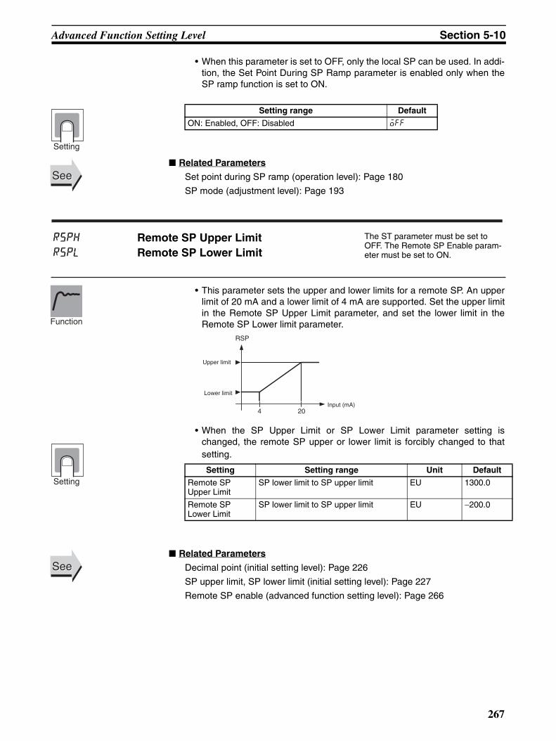
Advanced Function Setting Level Section 5-10
• When this parameter is set to OFF, only the local SP can be used. In addi-tion, the Set Point During SP Ramp parameter is enabled only when theSP ramp function is set to ON.
Related Parameters
Set point during SP ramp (operation level): Page 180
SP mode (adjustment level): Page 193
• This parameter sets the upper and lower limits for a remote SP. An upperlimit of 20 mA and a lower limit of 4 mA are supported. Set the upper limitin the Remote SP Upper Limit parameter, and set the lower limit in theRemote SP Lower limit parameter.
• When the SP Upper Limit or SP Lower Limit parameter setting ischanged, the remote SP upper or lower limit is forcibly changed to thatsetting.
Related Parameters
Decimal point (initial setting level): Page 226
SP upper limit, SP lower limit (initial setting level): Page 227
Remote SP enable (advanced function setting level): Page 266
Setting range Default
ON: Enabled, OFF: Disabled off
Setting
SeeSee
rsph
rspl
Remote SP Upper LimitRemote SP Lower Limit
The ST parameter must be set to OFF. The Remote SP Enable param-eter must be set to ON.
Setting Setting range Unit Default
Remote SP Upper Limit
SP lower limit to SP upper limit EU 1300.0
Remote SP Lower Limit
SP lower limit to SP upper limit EU −200.0
Function
4
RSP
20
Upper limit
Lower limit
Input (mA)
Setting
SeeSee
267

Advanced Function Setting Level Section 5-10
• This parameter specifies the operation for when the mode is changedfrom Remote SP Mode to Local SP Mode.
• When this parameter is set to ON, Local SP Mode inherits the remote SP.
• When this parameter is set to OFF, the local SP is not affected by theremote SP.
Related Parameters
Set point during SP ramp (operation level): Page 180
SP mode (adjustment level): Page 193
• When this parameter is set to ON, the output to which alarm 1 is assignedturns ON when a remote SP input error occurs.
Note For details on input errors, refer to 4-23 Using a Remote SP Func-tion.
• The output is an OR output between alarm 1, the heater burnout/HS/heater overcurrent alarm, the input error, and the RSP input error status.
• The output turns OFF when switching to the initial setting level, advancedfunction setting level, communications setting level, or calibration level.
Related Parameters
Remote SP upper limit, Remote SP lower limit (advanced function settinglevel): Page 267
SP mode (adjustment level): Page 193
sptr SP TrackingThe ST parameter must be set to OFF.The Remote SP Enable parameter must be set to OFF.
Setting range Default
ON: Enabled, OFF: Disabled off
Function
Setting
SeeSee
rseoRemote SP Input Error Output
The ST parameter must be set to OFF.The Remote SP Enable parameter must be set to ON.
Alarm 1 must be assigned, but not to a work bit output.
Setting range Default
ON: Enabled, OFF: Disabled off
Function
Setting
SeeSee
268

Advanced Function Setting Level Section 5-10
• This parameter provides the data for automatic selection of the PID set.
• The PID set number to be used is automatically selected according to thedata set in the PID Set Automatic Selection Data parameter. The selec-tion range is specified in the PID Set Automatic Selection Range UpperLimit parameter.
• The PID Set Automatic Selection Hysteresis parameter is used to set thehysteresis to prevent chattering when the PID set is changed.
Related Parameters
PID set automatic selection range upper limit (PID setting level): Page 269
Bank * PID set No. (bank setting level): Page 210
• For position-proportional models, control is executed with the processvalue equal to the set point when the process value is within the PV deadband.
• This function prevents unnecessary outputs when the process valueapproaches the set point.
Related Parameters
Closed/floating (initial setting level): Page 239
Motor calibration (initial setting level): Page 240
Travel time (initial setting level): Page 240
Position proportional dead band (adjustment level): Page 207
Open/close hysteresis (adjustment level): Page 207
pidi
pidh
PID Set Automatic Selection DataPID Set Automatic Selection Hysteresis
The control must be set to 2-PID control.
Parameter Setting range Unit Default
PID Set Automatic Selec-tion Data
pv: Process valuedv: Deviationsp: Set point
--- PV
PID Set Automatic Selec-tion Hysteresis
0.10 to 99.99 %FS 0.50
Function
Setting
SeeSee
p-db PV Dead Band Position-proportional control must be supported.
Setting range Unit Default
0 to 32400 EU 0.0
Function
Setting
SeeSee
269

Advanced Function Setting Level Section 5-10
This parameter sets whether the MV Upper Limit and MV Lower Limit param-eters are to be enabled for manual MV in manual mode.
Related Parameters
PID * MV upper limit, PID * MV lower limit (PID setting level): Page 217
• When this parameter is set to ON, valve opening can be specified in theMV at Stop, MV at PV Error, and Manual MV Limit Enable parameters.
Related Parameters
MV at stop (adjustment level): Page 204
MV at PV error (adjustment level): Page 204
Manual MV (manual control level): Page 221
manl Manual MV Limit EnableThe control must be set to 2-PID control.Close control (position-proportional models) must be used.
Setting range Default
on: Enabled, off: Disabled OFF
Function
Setting
SeeSee
pmvdDirect Setting of Position Proportional MV
Close control (position-proportional models) must be used.
Setting range Default
on: Enabled, off: Disabled OFF
Function
Setting
SeeSee
270

Advanced Function Setting Level Section 5-10
• The change width can be found for PV input values in any set period. Dif-ferences with previous values in each set period are calculated, and analarm is output if the results exceed the alarm value.
• The PV rate of change calculation period can be set in units of 60 ms(sampling period).
Related Parameters
Process value, Process value/set point (operation level): Page 177
Alarm 1 to 3 type, (Initial setting level): Pages 231, 233, 234.
• By setting the Automatic Cooling Coefficient Adjustment parameter toON, autotuning can be executed during heating/cooling control to auto-matically calculate the cooling coefficient at the same time as the PIDparameters. If there is strong non-linear gain for the cooling characteris-tics, such as when cooling water boils for cooling control, it may not bepossible to obtain the optimum cooling coefficient with this function, andcontrol may take the form of oscillating waves. If that occurs, increase theproportional band or the cooling coefficient to improve control.
Related Parameters
PID * cooling coefficient (PID setting level): Page 219
pvrp PV Rate of Change Calculation Period Alarms 1, 2, and 3 must be assigned. The alarm type must be set to 13.
Setting range Unit Default
1 to 999 Sampling period 17 (= 17 × 60 ms = 1020 ms)
Function
Setting
SeeSee
cscaAutomatic Cooling Coefficient Adjust-ment
The control must be set to heating/cooling control and 2-PID control.
Setting range Default
on: Enabled, off: Disabled OFF
Function
Setting
SeeSee
271

Advanced Function Setting Level Section 5-10
• Set this parameter to use the heater overcurrent alarm.
• When this parameter is set to ON, the HS alarm is held until any of the fol-lowing conditions is satisfied.
a Heater overcurrent detection is set to 50.0 A.
b The power is cycled.
c The latch is cancelled by the PF Key. (PF Setting = LAT: Alarm Latch Cancel)
d The latch is cancelled by an event input. (Event Input Assignment 1 to 4 = LAT: Alarm Latch Cancel)
• Output is turned OFF when switching to the initial setting level, communi-cations setting level, advanced function setting level, or calibration level.
Related Parameters
Heater overcurrent detection 1, Heater overcurrent detection 2 (adjustmentlevel): Pages 195, 196
Heater overcurrent use (advanced function setting level): Page 272
Heater overcurrent hysteresis (advanced function setting level): Page 273
Event input assignment 1 to 4 (initial setting level): Page 238
HB ON/OFF: Page 246, PF setting: Page 273 (advanced function settinglevel)
ocu Heater Overcurrent UseHeater burnout, HS alarms, and heater overcurrent detection must be supported.
Alarm 1 must be assigned.
Setting range Default
on: Enabled, off: Disabled ON
Function
Setting
ocl Heater Overcurrent LatchHeater burnout, HS alarms, and heater overcurrent detection must be supported (two CTs).
Alarm 1 must be assigned.
Setting range Default
on: Enabled, off: Disabled OFF
Function
Setting
SeeSee
272

Advanced Function Setting Level Section 5-10
• This parameter sets the hysteresis for heater overcurrent detection.
Related Parameters
Heater overcurrent use (advanced function setting level): Page 272
• This parameter sets the function of the PF Key.
The default setting is A-M (Auto/Manual).
Note (1) When AT cancel is specified, it means that AT is cancelled regardless ofwhether the AT currently being executed is 100% AT or 40% AT.
och Heater Overcurrent Hysteresis
Heater burnout, HS alarms, and heater overcurrent detection must be supported, and alarm 1 must be assigned. The Heater Overcurrent Use parameter must be set to ON, and the Heater Overcurrent Latch parameter must be set to OFF.
Setting range Unit Default
0.1 to 50.0 A 0.1
Function
Setting
SeeSee
pf PF Setting The PF Key must be supported (E5AN/EN-H).
Set value Setting Function
OFF: off Disabled Does not operate as a function key.
RUN: run RUN Specifies RUN status.
STOP: stop STOP Specifies STOP status.
R-S: r-s Reversing RUN/STOP operation
Specifies reversing RUN/STOP opera-tion status.
AT-2: at-2 100%ATExecute/Cancel
Specifies reversing 100% AT Execute/Cancel status. (See note 1.)
AT-1: at-1 40%ATExecute/Cancel
Specifies reversing 40% AT Execute/Cancel status. (See notes 1 and 2.)
LAT: lat Alarm Latch Cancel Specifies canceling alarm latches. (See note 3.)
A-M: a-m Auto/Manual Specifies reversing Auto/Manual status (See note 4.)
PFDP: pfdp Monitor/Setting Item Specifies the monitor/setting item dis-play. Select the monitor/setting item using the Monitor/Setting Item 1 to 5 parameters (advanced function setting level).
BANK: bank Bank No. Specifies switching to the bank number + 1.
Function
Setting
273

Advanced Function Setting Level Section 5-10
(2) The setting of this function will be ignored for heating/cooling control orposition-proportional (floating) control.
(3) Alarms 1 to 3, heater burnout, HS alarms, and heater overcurrent latchesare cancelled.
(4) For details on auto/manual operations using the PF Key, refer to 4-13 Per-forming Manual Control.
Related Parameters
Monitor/setting item 1 to 5 (advanced function setting level): Page 274
• Set the PF Key parameter to Monitor/Setting Item to enable using thefunction key to display monitor/setting items. The items that will be dis-played are set using the Monitor/Setting Item 1 to 5 parameters. The set-tings are listed in the following table.
Note The MV for heating and cooling control is set in the MV Display Selectionparameter.
Related Parameters
PF setting: Page 273, MV display selection: Page 275 (advanced function set-ting level)
SeeSee
pfd* Monitor/Setting Item * (*: 1 to 5) The PF Setting parameter must be set to PFDP.
Function
Setting
Set value Setting Remarks
Monitor/Setting Symbol
0 Disabled ---
1 PV/SP/Bank No. Can be set. (SP) ---
2 PV/SP/MV (See note.) Can be set. (SP) ---
3 PV/SP/Soak time remain Can be set. (SP) ---
4 Proportional band (P) Can be set. p
5 Integral time (I) Can be set. i
6 Derivative time (D) Can be set. d
7 Alarm value 1 Can be set. al-1
8 Alarm value upper limit 1 Can be set. al1h
9 Alarm value lower limit 1 Can be set. al1l
10 Alarm value 2 Can be set. al-2
11 Alarm value upper limit 2 Can be set. al2h
12 Alarm value lower limit 2 Can be set. al2l
13 Alarm value 3 Can be set. al-3
14 Alarm value upper limit 3 Can be set. al3h
15 Alarm value lower limit 3 Can be set. al3l
16 Bank No. Can be set. bank
SeeSee
274

Advanced Function Setting Level Section 5-10
• This parameter sets the PV/SP Screen No. 3 display and order of display.
• The default is 4.
Note The MV for heating and cooling control is set in the MV Display Selectionparameter.
Related Parameters
Process value/set point (operation level): Page 177
MV display selection (advanced function setting level): Page 275
• This parameter selects the MV display for PV/SP/MV during heating andcooling control. Either heating MV or cooling MV can be selected.
spdp PV/SP Display Screen Selection The No. 3 display must be supported (E5AN/EN-H).
Set value Display contents
0 Only PV/SP is displayed (with no No. 3 display).
1 PV/SP/Bank No. and PV/SP/MV are displayed in order. (See note.)
2 PV/SP/MV and PV/SP/Bank No. are displayed in order. (See note.)
3 Only PV/SP/Bank No. is displayed.
4 PV/SP/MV is displayed (See note.)
5 PV/SP/Bank No. and PV/SP/Soak time remain are dis-played in order.
6 PV/SP/MV and PV/SP/Soak time remain are displayed in order. (See note.)
7 Only PV/SP/Soak time remain is displayed.
Function
Setting
SeeSee
odsl MV Display Selection
The No. 3 display must be supported (E5AN/EN-H).
Heating and cooling control must be used.
The PV/SP Display Screen Selection parameter must be set to 1, 2, 4, or 6, or the Monitor/Setting Item 1 to 5 parameter must be set to 2.
Setting range Default
o: MV (heating)
c-o: MV (cooling)
o
Function
Setting
275

Advanced Function Setting Level Section 5-10
The display below the decimal point in the PV can be hidden for temperatureinputs.
• The PV decimals below the decimal point can be hidden by setting the PVDecimal Point Display parameter to OFF. When this parameter is set toON, the display below the decimal point will appear according to the inputtype setting.
Related Parameters
Input type (initial setting level): Page 224
• The PV in the No. 1 display for the PV/SP, PV, or PV/Manual MV (ValveOpening) Screen is alternately displayed in 0.5-s cycles with the controland alarm status specified for the PV status display function.
Related Parameters
Process value/set point, PV (operation level): Page 177
PV/MV (manual MV) (manual control level): Page 221
pvdp PV Decimal Point Display The input type must be set to tem-perature input.
Setting range Default
on: ON, off: OFF ON
Function
Setting
SeeSee
pvst PV Status Display Function
Monitor range Default
off: No PV status display off
manu: MANU is alternately displayed during manual control.
stop: STOP is alternately displayed while operation is stopped.
alm1: ALM1 is alternately displayed during Alarm 1 status.
alm2: ALM2 is alternately displayed during Alarm 2 status.
alm3: ALM3 is alternately displayed during Alarm 3 status.
alm: ALM is alternately displayed when Alarm 1, 2, or 3 is set to ON.
ha: HA is alternately displayed when a heater burnout alarm, HS alarm, or heater overcurrent alarm is ON.
Monitor
SeeSee
276

Advanced Function Setting Level Section 5-10
• The SP, Blank, or Manual MV in the No. 2 display for the PV/SP, PV, orPV/Manual MV (Valve Opening) Screen is alternately displayed in 0.5-scycles with the control and alarm status specified for the SV status displayfunction.
Related Parameters
Process value/set point, PV (operation level): Page 177
PV/MV (manual MV) (manual control level): Page 221
• This parameter delays the display refresh period for monitor values. Onlydisplay refreshing is delayed, and the refresh period for process valuesused in control is not changed.
• This function is disabled by setting the parameter to OFF.
svst SV Status Display Function
Monitor range Default
off: No SV status display off
manu: MANU is alternately displayed during manual control.
stop: STOP is alternately displayed while operation is stopped.
alm1: ALM1 is alternately displayed during Alarm 1 status.
alm2: ALM2 is alternately displayed during Alarm 2 status.
alm3: ALM3 is alternately displayed during Alarm 3 status.
alm: ALM is alternately displayed when Alarm 1, 2, or 3 is set to ON.
ha: HA is alternately displayed when a heater burnout alarm, HS alarm, or heater overcurrent alarm is ON.
Function
Monitor
SeeSee
d.ref Display Refresh Period
Setting range Unit Default
OFF, 0.25, 0.5, 1.0 Second 0.25
Function
Monitor
277

Advanced Function Setting Level Section 5-10
• This parameter monitors the number of times that control output 1 isturned ON and OFF.
• This function is not displayed when the set value is 0, or when the controloutput is a linear output.
• This parameter monitors the number of times that control output 2 isturned ON and OFF.
• This function is not displayed when the set value is 0, or when the controloutput is a linear output.
ra1m Control Output 1 ON/OFF Count Monitor
Control output 1 must be supported.
A relay output, voltage output (for driving SSR), or SSR output must be used.
The Control Output 1 ON/OFF Count Alarm Set Value parameter must not be set to 0.
Monitor range Unit
0 to 9999 100 times
Function
Monitor
ra2m Control Output 2 ON/OFF Count Monitor
Control output 2 must be supported.
Relay, voltage outputs (for driving SSR), or SSR output must be used.The Control Output 2 ON/OFF Count Alarm Set Value parameter must not be set to 0.
Monitor range Unit
0 to 9999 100 times
Function
Monitor
278

Advanced Function Setting Level Section 5-10
• An ON/OFF count alarm occurs when the ON/OFF counter exceeds thevalue set for this parameter.
• It is possible to assign ON/OFF count alarms to auxiliary outputs and tohave them displayed on the screen.
• This function is disabled when the set value is 0.
Related Parameters
Control output 1 ON/OFF count monitor (advanced function setting level):Page 278
• An ON/OFF count alarm occurs when the ON/OFF counter exceeds thevalue set for this parameter.
• It is possible to assign ON/OFF count alarms to auxiliary outputs and tohave them displayed on the screen.
• This function is disabled when the set value is 0.
Related Parameters
Control output 2 ON/OFF count monitor (advanced function setting level):Page 278
ra1Control Output 1 ON/OFF Count Alarm Set Value
Control output 1 must be supported.
Relay, voltage outputs (for driving SSR), or SSR output must be used.
Setting range Unit Default
0 to 9999 100 times 0
Function
Monitor
SeeSee
ra2Control Output 2 ON/OFF Count Alarm Set Value
Control output 2 must be supported.
Relay, voltage outputs (for driving SSR), or SSR output must be used.
Setting range Unit Default
0 to 9999 100 times 0
Function
Monitor
SeeSee
279

Advanced Function Setting Level Section 5-10
• This parameter resets the ON/OFF counter for specified control outputs.
Note After the counter has been reset, the set value will be automatically returnedto 0.
Related Parameters
Control output 1 ON/OFF count monitor, Control output 2 ON/OFF count mon-itor (advanced function setting level): Page 278
This parameter sets the password to move to the calibration level.
• Set the password to move to the calibration level. The password is 1201.
• Move to the calibration level either by pressing the M Key or O Key or bywaiting for two seconds to elapse.
Related Parameter
Initial setting/communications protect (protect level): Page 172
rac ON/OFF Counter ResetControl outputs 1 and 2 must be sup-ported.Relay, or voltage outputs (for driving SSR), or SSR output must be used.
Setting range Default
0: Disable the counter reset function.
1: Reset the control output 1 ON/OFF counter.2: Reset the control output 2 ON/OFF counter.
0
Function
Setting
SeeSee
cmov Move to Calibration Level Initial setting/communications protect must be 0.
Function
SeeSee
280

Communications Setting Level Section 5-11
5-11 Communications Setting Level
• Each parameter is enabled when the power is reset.
• Match the communications specifications of the E5@N-H and the hostcomputer. If multiple devices are connected, ensure that the communica-tions specifications for all devices in the system (except the Communica-tions unit number) are the same.
Related Parameter
Communications writing (adjustment level): Page 193
psel Protocol Setting Communications must be supported.
u-no Communications Unit No.bps Communications Baud Ratelen Communications Data Length CompoWay/F must be selected as the protocol.
sbit Communications Stop Bits CompoWay/F must be selected as the protocol.
prty Communications Paritysdwt Send Data Wait Time
Item Symbol Set values Settings Default
Protocol setting psel cwf, mod CompoWay/F (SYSWAY), Modbus
cwf
Communications Unit No.
u-no 0 to 99 0 to 99 1
Communications baud rate
bps 1.2, 2.4, 4.8, 9.6, 19.2, 38.4, or 57.6 (kbps)
1.2, 2.4, 4.8, 9.6, 19.2, 38.4, or 57.6 (kbps)
9.6
Communications data length
len 7 or 8 bits 7 or 8 bits 7
Stop bits sbit 1 or 2 bits 1 or 2 bits 2
Communications parity
prty none, even, odd None, Even, Odd even
Send data wait time sdwt 0 to 99 0 to 99 (ms) 20
SeeSee
281

Communications Setting Level Section 5-11
282

SECTION 6CALIBRATION
This section describes how the user can calibrate the E5CN-H Digital Controllers.
6-1 Parameter Structure. . . . . . . . . . . . . . . . . . . . . . . . . . . . . . . . . . . . . . . . . . . . . 284
6-2 User Calibration . . . . . . . . . . . . . . . . . . . . . . . . . . . . . . . . . . . . . . . . . . . . . . . 285
6-2-1 Calibrating Inputs . . . . . . . . . . . . . . . . . . . . . . . . . . . . . . . . . . . . . . . 285
6-2-2 Registering Calibration Data . . . . . . . . . . . . . . . . . . . . . . . . . . . . . . 285
6-3 Thermocouple Calibration (Thermocouple/Resistance Thermometer Input) . 285
6-3-1 Preparations . . . . . . . . . . . . . . . . . . . . . . . . . . . . . . . . . . . . . . . . . . . 286
6-4 Platinum Resistance Thermometer Calibration(Thermocouple/Resistance Thermometer Input) . . . . . . . . . . . . . . . . . . . . . . 289
6-5 Calibrating Analog Input (Analog Input) . . . . . . . . . . . . . . . . . . . . . . . . . . . . 290
6-5-1 Calibrating a Current Input. . . . . . . . . . . . . . . . . . . . . . . . . . . . . . . . 290
6-5-2 Calibrating a Voltage Input . . . . . . . . . . . . . . . . . . . . . . . . . . . . . . . . 291
6-6 Calibrating the Transfer Output . . . . . . . . . . . . . . . . . . . . . . . . . . . . . . . . . . . 292
6-7 Checking Indication Accuracy . . . . . . . . . . . . . . . . . . . . . . . . . . . . . . . . . . . . 294
6-7-1 Thermocouple . . . . . . . . . . . . . . . . . . . . . . . . . . . . . . . . . . . . . . . . . . 294
6-7-2 Platinum Resistance Thermometer . . . . . . . . . . . . . . . . . . . . . . . . . . 294
6-7-3 Analog Input . . . . . . . . . . . . . . . . . . . . . . . . . . . . . . . . . . . . . . . . . . . 295
283

Parameter Structure Section 6-1
6-1 Parameter Structure• To execute user calibration, enter the password “1201” at the Move to Cal-
ibration Level parameter in the advanced function setting level. The modewill be changed to the calibration mode, and adj will be displayed.
• The Move to Calibration Level parameter may not be displayed. If thishappens, set the Initial/Communications Protect parameter in the protectlevel to 0 before moving to the advanced function setting level. (Thedefault setting is 0.)
• The calibration mode is ended by turning the power OFF.
• The parameter calibrations in the calibration mode are structured asshown below.
Controllers with Thermocouple/Resistance Thermometer Universal Inputs
21: K22: J23: T
5: K7: J11: E12: L15: N19: W20: PLII
6: K8: J9, 10: T13, 14: U16: R17: S18: B
1: Pt1002: Pt1003: JPt1004: JPt10024: Pt100
0: Pt100 25: 4 to 20 mA 26: 0 to 20 mA
27: 1 to 5 V 28: 0 to 5 V
29: 0 to 10 V
Advanced Function Setting Level
Moves automatically according to input type.
Platinum resistance thermometer Thermocouple
Note: This is displayed only for Controllers that have a transfer output (E5AN/EN-H@@F).
adj
30
p390
e20c
p280
e26b
t 54
b9a5
t 24
e220
a 20
c8e7
a 1
4677
t -6
0200
t -6
2988
p 10
4543
p 10
4543
c400
29be
c700
ba13
c400
29be
c700
ba13
str
no
bia5
35b8
bia5
35b8
p200
93a7
p140
93d7
1v 5
c7c3
1v 1
5ac0
2v10
b104
2v 1
4ad9
Analog input
Transfer Output Calibration
284

User Calibration Section 6-2
When calibration has been performed after purchase, the user calibrationinformation shown in the following illustration will be displayed when moving tothe calibration level.
6-2 User CalibrationThe E5@N-H is correctly calibrated before it is shipped from the factory, andnormally need not be calibrated by the user.
If, however, it must be calibrated by the user, use the parameters for calibrat-ing temperature input and analog input. OMRON, however, cannot ensure theresults of calibration by the user. Also, calibration data is overwritten with thelatest calibration results. The default calibration settings cannot be restoredafter user calibration. Perform user calibration with care.
6-2-1 Calibrating InputsThe input type selected in the parameter is used for calibration. The inputtypes are as follows:
Controllers with Thermocouple, Resistance Thermometer, Analog UniversalInputs
• Thermocouple: 19 types
• Analog input: 5 types
• Platinum resistance thermometer: 6 types
6-2-2 Registering Calibration DataThe new calibration data for each item is temporarily registered. It can be offi-cially registered as calibration data only when all items have been calibratedto new values. Therefore, be sure to temporarily register all items when youperform the calibration. When the data is registered, it is also recorded thatuser calibration has been performed.
Prepare separate measuring devices and equipment for calibration. Fordetails on how to handle measuring devices and equipment, refer to therespective instruction manuals.
6-3 Thermocouple Calibration (Thermocouple/Resistance Thermometer Input)
• Calibrate according to the type of thermocouple: thermocouple 1 group(input types 5, 7, 11, 12, 15, 19, 20) and thermocouple 2 group (inputtypes 6, 8, 9, 10, 13, 14, 16, 17, 18, 21, 22, 23).
• When calibrating, do not cover the bottom of the Controller. Also, do nottouch input terminals/pins (terminals 4 and 5 on the E5CN-H, and pins 19and 20 on the E5AN/EN-H) or compensating conductors.
.adj30
A dot is displayed.
285

Thermocouple Calibration (Thermocouple/Resistance Thermometer Input) Section 6-3
6-3-1 Preparations
• Set the cold junction compensator designed for compensation of internalthermocouples to 0°C. Make sure that internal thermocouples are dis-abled (i.e., that tips are open).
• In the above figure, STV indicates a standard DC current/voltage source.
• Use the compensating conductor designed for the selected thermocou-ple. When thermocouples R, S, E, B, W, or PLII is used, the cold junctioncompensator and the compensating conductor can be substituted withthe cold junction compensator and the compensating conductor for ther-mocouple K.
Connecting the Cold Junction Compensator
Correct process values cannot be obtained if you touch the contact ends ofthe compensating conductor during calibration of a thermocouple. Accord-ingly, short-circuit (enable) or open (disable) the tip of the thermocouple insidethe cold junction compensator as shown in the figure below to create a con-tact or non-contact state for the cold junction compensator.
E5CN-HSTV
0°C/32°F
4
5
9
10
−
+
Input power supply
Compensating conductor
Cold junction compensator
E5AN/EN-HSTV
0°C/32°F
19
20
2
1
−
+
Input power supply
Compensating conductor
Cold junction compensator
E5@N-H 0°C/32°F 0°C/32°F
Compensating conductor Compensating conductor
Cold junction compensator Cold junction compensator
Short-circuit
OpenE5@N-H
286

Thermocouple Calibration (Thermocouple/Resistance Thermometer Input) Section 6-3
In this example, calibration is shown for a Controller with a thermocouple setas the input type.
1,2,3... 1. Connect the power supply.
2. Connect a standard DC current/voltage source (STV), precision digitalmultimeter (DMM), and contact junction compensator (e.g., a zero con-troller as in the figure) to the thermocouple input terminals, as shown inthe figure below.
3. Turn the power ON.
4. Move to the calibration level.This starts the 30-minute aging timer. This timer provides an approximatetimer for aging. After 30 minutes have elapsed, the No. 2 display changesto 0. You can advance to the next step in this procedure even if 0 is notdisplayed.
Input types 5, 7, 11, 12, 15, 19, 20:
Input types 6, 8, 9, 10, 13, 14, 16, 17, 18, 21, 22, 23:
5. When the M Key is pressed, the status changes as shown to the left.The No. 2 display at this time shows the currently entered count value inhexadecimal. Set the STV as follows:
• Input types 5, 7, 11, 12, 15, 19, 20: Set to 54 mV.
• Input types 6, 8, 9, 10, 13, 14, 16, 17, 18, 21, 22, 23: Set to 24 mV.
Allow the count value on the No. 2 display to fully stabilize, then press theD Key to temporarily register the calibration settings.If this count value is outside of the specified range, the No. 2 display willflash and the count value will not be temporarily registered.
6. When the M Key is pressed, the status changes as shown to the left.Set the STV to −6 mV.Allow the count value on the No. 2 display to fully stabilize, then press theD Key to temporarily register the calibration settings.If this count value is outside of the specified range, the No. 2 display willflash and the count value will not be temporarily registered.
7. Press the M Key. The display changes as shown on the left. Set the STVto 700 mV.Allow the count value on the No. 2 display to fully stabilize, then press theD Key to temporarily register the calibration settings.If this count value is outside of the specified range, the No. 2 display willflash and the count value will not be temporarily registered.
STV
DMM
OUTPUT INPUT
−
+Leave open.
Compensating conductor of currently selected thermocoupleUse K thermocouple compensating conductor for E, R, S, B, W, and PLII thermocouples.
Zero controller
adj30
t-54b9a5
t-24e220
t--62988
c700-ba13
287

Thermocouple Calibration (Thermocouple/Resistance Thermometer Input) Section 6-3
8. Press the M Key. The display changes as shown on the left. Set the STV to 400 mV.Allow the count value on the No. 2 display to fully stabilize, then press theD Key to temporarily register the calibration settings.If this count value is outside of the specified range, the No. 2 display willflash and the count value will not be temporarily registered.
9. When the M Key is pressed, the status changes as shown to the left.
10. Change the wiring as follows:
Disconnect the STV to enable the thermocouple of the cold junction com-pensator. When doing this, be sure to disconnect the wiring on the STVside.
11. Allow the count value on the No. 2 display to fully stabilize, then press theD Key to temporarily register the calibration settings.
12. When the M Key is pressed, the status changes as shown to the left.The data to be temporarily registered is not displayed if it is not complete.Press the U Key. The No. 2 display changes to yes. Release the key andwait two seconds or press the M Key. This stores the temporarily regis-tered calibration data to EEPROM. To cancel the saving of temporarilyregistered calibration data to EEPROM, press the M Key (while no is dis-played in the No. 2 display) without pressing the U Key.
13. The calibration mode is ended by turning the power OFF.
For Controllers that have a transfer output (E5AN/EN-H@@F), transferoutput calibration continues to be performed. For details on the settings,refer to 6-6 Calibrating the Transfer Output on page 292.
c400429be
bias35b8
STV
DMM
OUTPUT INPUT
−
+
Open in non-connected state
Short-circuit
Compensating conductor of currently selected thermocoupleUse K thermocouple compensating conductor for E, R, S, B, W and PLII thermocouple.
Zero controller
strno
288

Platinum Resistance Thermometer Calibration (Thermocouple/Resistance Thermometer Input) Section 6-4
6-4 Platinum Resistance Thermometer Calibration (Thermocouple/Resistance Thermometer Input)
In this example, calibration is shown for Controller with a resistance thermom-eter set as the input type.
Use connecting wires of the same thickness.
1,2,3... 1. Connect the power supply.
2. Connect a precision resistance box (called a “6-dial” in this manual) to theplatinum resistance thermometer input terminals, as shown in the follow-ing diagram.
3. Turn the power ON.
4. Move to the calibration level.This starts the 30-minute aging timer. This timer provides an approximatetimer for aging. After 30 minutes have elapsed, the No. 2 display changesto 0. You can advance to the next step in this procedure even if 0 is notdisplayed.
Input type 0:
Input types 1, 2, 3, 4, 24:
5. Execute calibration for the main input.Press the M Key to display the count value for each input type.The No. 2 display at this time shows the currently entered count value inhexadecimal. Set the 6-dial as follows:
• Input type 0: 390 Ω• Input type 1, 2, 3, 4 or 24: 280 Ω
Allow the count value on the No. 2 display to fully stabilize, then press theD Key to temporarily register the calibration settings.If this count value is outside of the specified range, the No. 2 display willflash and the count value will not be temporarily registered.
Input type 0: Press the M Key to display the count value for each input type.
The No. 2 display at this time shows the currently entered count value inhexadecimal. Set the 6-dial as follows:
• Input type 0: 200 Ω• Input type 1, 2, 3, 4 or 24: 140 Ω
Input types 1, 2, 3, 4, 24: Allow the count value on the No. 2 display to fully stabilize, then press theD Key to temporarily register the calibration settings.
If this count value is outside of the specified range, the No. 2 display willflash and the count value will not be temporarily registered.
E5CN-H
4
3
5
10
9
A
B'
B6-dial
Input power supply
E5AN/EN-H
19
18
20
2
1
A
B'
B
6-dial
Input power supply
adj30
p390e20c
p280e26b
p20093a7
p140e26b
289

Calibrating Analog Input (Analog Input) Section 6-5
6-5 Calibrating Analog Input (Analog Input)
6-5-1 Calibrating a Current InputIn this example, calibration is shown for a Controller with a current input set asthe input type.
6. When the M Key is pressed, the status changes as shown to the left.Set the 6-dial to 10 Ω.
Allow the count value on the No. 2 display to fully stabilize, then press theD Key to temporarily register the calibration settings.If this count value is outside of the specified range, the No. 2 display willflash and the count value will not be temporarily registered.
7. When the M Key is pressed, the status changes as shown to the left.The data to be temporarily registered is not displayed if it is not complete.Press the U Key. The No. 2 display changes to yes. Release the key andwait two seconds or press the M Key. This stores the temporarily regis-tered calibration data to EEPROM.To cancel the saving of temporarily registered calibration data to EE-PROM, press the M Key (while no is displayed in the No. 2 display) with-out pressing the U Key.
8. The calibration mode is quit by turning the power OFF.For Controllers that have a transfer output (E5AN/EN-H@@F), transfer output calibration continues to be performed. For details on the settings, refer to 6-6 Calibrating the Transfer Output on page 292.
p-104543
strno
1,2,3... 1. Connect the power supply.
2. Connect an STV and DMM to the current input terminals, as shown in thefollowing diagram.
3. Turn the power ON.
4. Move to the calibration level.This starts the 30-minute aging timer. This timer provides an approximatetimer for aging. After 30 minutes have elapsed, the No. 2 display changesto 0. You can advance to the next step in this procedure even if 0 is notdisplayed.
5. When the M Key is pressed, the status changes as shown to the left.The No. 2 display at this time shows the currently entered count value inhexadecimal. Set the STV to 20 mA.
Allow the count value on the No. 2 display to fully stabilize, then press theD Key to temporarily register the calibration settings.If this count value is outside of the specified range, the No. 2 display willflash and the count value will not be temporarily registered.
STV
E5CN-H
DMM
+
−
9
10
3
4
Input power supply
STV
E5AN/EN-H
DMM
+
−
1
2
18
19
Input power supply
adj30
a-20c8e7
290

Calibrating Analog Input (Analog Input) Section 6-5
6-5-2 Calibrating a Voltage InputIn this example, calibration is shown for a Controller with a voltage input set asthe input type.
6. When the M Key is pressed, the status changes as shown to the left.Set the STV to 1 mA.
Allow the count value on the No. 2 display to fully stabilize, then press theD Key to temporarily register the calibration settings.If this count value is outside of the specified range, the No. 2 display willflash and the count value will not be temporarily registered.
7. When the M Key is pressed, the status changes as shown to the left.The data to be temporarily registered is not displayed if it is not complete.Press the U Key. The No. 2 display changes to yes. Release the key andwait two seconds or press the M Key. This stores the temporarily regis-tered calibration data to EEPROM.To cancel the saving of temporarily registered calibration data to EE-PROM, press the M Key (while no is displayed in the No. 2 display) with-out pressing the U Key.
8. The calibration mode is ended by turning the power OFF.
For Controllers that have a transfer output (E5AN/EN-H@@F), transferoutput calibration continues to be performed. For details on the settings,refer to 6-6 Calibrating the Transfer Output on page 292.
a--14677
strno
1,2,3... 1. Connect the power supply.
2. Connect an STV and DMM to the voltage input terminals, as shown in thefollowing diagram.
3. Turn the power ON.
4. Move to the calibration level.This starts the 30-minute aging timer. This timer provides an approximatetimer for aging. After 30 minutes have elapsed, the No. 2 display changesto 0. You can advance to the next step in this procedure even if 0 is notdisplayed.
Input type 27 or 28:
Input type 29:
5. When the M Key is pressed, the status changes as shown to the left.The No. 2 display at this time shows the currently entered count value inhexadecimal. Set the STV as follows:
• Input type 27 or 28: 5 V
• Input type 29: 10 V
Allow the count value on the No. 2 display to fully stabilize, then press theD Key to temporarily register the calibration settings.If this count value is outside of the specified range, the No. 2 display willflash and the count value will not be temporarily registered.
STV
E5CN-H
DMM
−
+
9
10
4
5
Input power supply
STV
E5AN/EN-H
DMM
−
+
1
2
19
17
Input power supply
adj30
1v-5c7c3
2v10b104
291

Calibrating the Transfer Output Section 6-6
6-6 Calibrating the Transfer Output
Input type 27 or 28:
Input type 29:
6. When the M Key is pressed, the status changes as shown to the left.Set the STV to 1 V.
Allow the count value on the No. 2 display to fully stabilize, then press theD Key to temporarily register the calibration settings.If this count value is outside of the specified range, the No. 2 display willflash and the count value will not be temporarily registered.
7. When the M Key is pressed, the status changes as shown to the left.The data to be temporarily registered is not displayed if it is not complete.Press the U Key. The No. 2 display changes to yes. Release the key andwait two seconds or press the M Key. This stores the temporarily regis-tered calibration data to EEPROM.To cancel the saving of temporarily registered calibration data to EE-PROM, press the M Key (while no is displayed in the No. 2 display) with-out pressing the U Key.
8. The calibration mode is ended by turning the power OFF.
For Controllers that have a transfer output (E5AN/EN-H@@F), transferoutput calibration continues to be performed. For details on the settings,refer to 6-6 Calibrating the Transfer Output on page 292.
For Controllers that have a transfer output (E5@N-H@@F), the Transfer Output Calibration Screen will be displayed after input calibration has been completed.
Use the following procedure for calibration.
1. Connect the DMM to the transfer output terminal.
1v-15ac0
2v-14ad9
strno
adj30
Advanced Function Setting Level
Main Input Calibration
Input calibration display
M
M
M
M
Note: This is displayed only for Controllers that have a transfer output (E5AN/EN-H@@F).
Transfer Output Calibration
E5AN/EN-H
+
−28
27
15
14
10
DMM
Input power supply
+
−
E5CN-H
DMM
Input power supply91
2
292

Calibrating the Transfer Output Section 6-6
2. Press the M Key to switch to the Transfer Output Screen.
3. The 20 mA Calibration Screen will be displayed. Use the U and D Keys to adjustthe DMM monitor value to 20 mA, and then press the M Key. The contents of thecalibration will be temporarily registered.
4. The 4 mA Calibration Screen will be displayed. Use the U and D Keys to adjustthe DMM monitor value to 4 mA, and then press the M Key. The contents of thecalibration will be temporarily registered.
5. Press the U Key. The No. 2 display changes to yes. Release the key and wait twoseconds or press the M Key. This stores the temporarily registered calibration datato EEPROM.To cancel the saving of temporarily registered calibration data to EEPROM, pressthe M Key (while no is displayed in the No. 2 display) without pressing the U Key.
6. The calibration mode is quit by turning the power OFF.
strno
a20.t52ac
a4.t0037
str.tno
293

Checking Indication Accuracy Section 6-7
6-7 Checking Indication Accuracy• After calibrating the input, be sure to check the indication accuracy to
make sure that the calibration has been executed correctly.
• Operate the E5@N-H in the process value/set point monitor mode.
• Check the indication accuracy at the following three values: upper limit,lower limit, and mid-point.
6-7-1 Thermocouple• Preparations
The diagram below shows the required device connections. Make surethat the E5CN/AN/EN-H and cold junction compensator are connected bya compensating conductor for the thermocouple that is to be used duringactual operation.
• OperationMake sure that the cold junction compensator is at 0°C, and set the STVoutput to the voltage equivalent of the starting power of the check value.The cold junction compensator and compensation conductor are notrequired when an external cold junction compensation method is used.
6-7-2 Platinum Resistance Thermometer• Preparations
The diagram below shows the required device connections.
• OperationSet the 6-dial to the resistance equivalent to the check value.
E5CN-H
4
5
9
10
STV−
+
Input power supplyCold junction compensator
Compensating conductor
E5AN/EN-H
19
20
1
2
STV−
+
Input power supplyCold junction compensator
Compensating conductor
E5CN-H
4
3
5
10
9
A
B'
B
Input power supply
6-dial
E5AN/EN-H
19
18
20
2
1
A
B'
B
Input power supply
6-dial
294

Checking Indication Accuracy Section 6-7
6-7-3 Analog Input• Preparations
The diagram below shows the required device connections.(The connection terminals depend on the model and input type.)
Current Input for a Controller with an Analog Input
Voltage Input for a Controller with an Analog Input
• OperationSet the STV output to the voltage or current equivalent to the check value.
E5CN-H
3
4
10
9
STV+
−
Input power supply
E5AN/EN-H
18
19
2
1
STV+
−
Input power supply
E5CN-H
4
5
10
9
STV−
+
Input power supply
E5AN/EN-H
19
17
2
1
STV−
+
Input power supply
295

Checking Indication Accuracy Section 6-7
296

Appendix
Specifications
Ratings
Note (1) For the setting ranges for each sensor input, see page 335.
(2) When connecting the ES2-THB, connect it 1:1.
(3) The E5AN-H and E5EN-H Output Units are sold separately. Refer to the following table.
Supply voltage 100 to 240 VAC, 50/60 Hz 24 VAC, 50/60 Hz/24 VDC
Operating voltage range 85% to 110% of rated supply voltage
Power consump-tion
E5CN-H 8.5 VA 5.5 VA/3.5 W
E5AN-H 12 VA 8.5 VA/5.5 W
E5EN-H 12 VA 8.5 VA/5.5 W
Sensor input (See note 1.) Temperature inputThermocouple: K, J, T, E, L, U, N, R, S, B, W, PLIIPlatinum resistance thermometer: Pt100, JPt100
Controllers with Analog (See note 2.)Current input: 4 to 20 mA, 0 to 20 mA (Input impedance: 150 Ω max.)Voltage input: 1 to 5 V, 0 to 5 V, 0 to 10 V (Input impedance: 1 MΩ max.)
Control output (See note 3.) Relay output E5CN-H Relay output:SPST-NO, 250 VAC, 3 A (resistive load), electrical dura-bility: 100,000 operationsMin. applicable load: 5 V, 10 mA
E5AN-HE5EN-H
Relay output: Open and closeSPST-NO, 250 VAC, 1 A (including inrush current), elec-trical durability: 100,000 operationsMin. applicable load: 5 V, 10 mA
Voltage output E5CN-H Output voltage 12 VDC ±15% (PNP), max. load current 21 mA, with short-circuit protection circuit
Current output E5CN-H 4 to 20 mA DC, 0 to 20 mA DC, Load: 600 Ω max., Resolution: approx. 10,000
Linear voltage output
E5CN-H 0 to 10 VDC,Load: 1 kΩ min., Resolution: approx. 10,000
SSR output E5AN-HE5EN-H
75 to 250 VAC , 1A (resistive load)
Auxiliary output E5CN-H SPST-NO, 250 VAC, 3 A (resistive load), electrical durability: 100,000 operationsMin. applicable load: 5 V, 10 mA
E5AN-HE5EN-H
SPST-NO, 250 VAC, 3 A (resistive load), electrical durability: 100,000 operationsMin. applicable load: 5 V, 10 mA
Control method 2-PID or ON/OFF control
Setting method Digital setting using front panel keys
Indication method 11-segment/7-segment digital display and single-lighting indicator
Other functions Depend on the model
Ambient temperature −10 to 55°C (with no condensation or icing); with 3-year guarantee: −10 to 50°CAmbient humidity 25% to 85%
Storage temperature −25 to 65°C (with no condensation or icing)
Altitude 2,000 m or less
Recommended fuse T2A, 250 VAC, time lag, low shut-off capacity
Installation environment Installation Category II, Pollution Class 2 (IEC 61010-1 compliant)
297

Appendix
E5AN-H/EN-H Output Unit Ratings
HB, HS, and Heater Overcurrent Alarms (for E5CN/AN/EN-H Controllers with Heater Burnout, HS, and Heater Overcurrent Alarms)
Note (1) When the control output 1 ON time is less than 100 ms, heater burnout detection, heater overcurrentdetection, and heater current measurement are not performed.
(2) When the control output 1 OFF time is less than 100 ms, HS alarm, and leakage current measure-ment are not performed.
Characteristics
Model Output type Output form Specifications
E53-RN Relay ON/OFF 250 VAC, 5 A (resistive load), electrical durability: 100,000 opera-tions
E53-QN
E53-Q3
E53-Q4
Voltage (PNP)
Voltage (NPN)
Voltage (PNP)
ON/OFF
ON/OFF
ON/OFF
PNP type, 12 VDC, 40 mA (with short-circuit protection)
NPN type, 24 VDC, 20 mA (with short-circuit protection)
PNP type, 24 VDC, 40 mA (with short-circuit protection)
E53-C3NE53-C3DN
4 to 20 mA0 to 20 mA
LinearLinear
4 to 20 mA DC, Load: 600 Ω max., Resolution: approx. 10,0000 to 20 mA DC, Load: 600 Ω max., Resolution: approx. 10,000
E53-V34N
E53-V35N
0 to 5 V
0 to 10 V
Linear
Linear
0 to 10 VDC, Load: 1 kΩ max., Resolution: approx. 10,000
0 to 5 VDC, Load: 1 kΩ max., Resolution: approx. 10,000
Max. heater current 50 A AC
Input current readout accuracy ±5% FS ±1 digit max.
Heater burnout alarm setting range
0.1 to 49.9 A (0.1 A units)0.0 A: Heater burnout alarm output turns OFF.50.0 A: Heater burnout alarm output turns ON.Min. detection ON time: 100 ms (See note 1.)
HS alarm setting range 0.1 to 49.9 A (0.1 A units)0.0 A: HS alarm output turns ON.50.0 A: HS alarm output turns OFF.Min. detection OFF time: 100 ms (See note 2.)
Heater overcurrent alarm setting range
0.1 to 49.9 A (0.1 A units)0.0 A: Heater overcurrent alarm output turns ON.50.0 A: Heater overcurrent alarm output turns OFF.Min. detection OFF time: 100 ms
Indication accuracy(ambient temperature of 23°C)
Thermocouple (See note 1.):(±0.1% of indication value or ±1°C, whichever is greater) ±1 digit max.
Platinum resistance thermometer:(±0.1% of indication value or ±0.5°C, whichever is greater) ±1 digit max.
Analog input: ±0.1% FS ±1 digit max.
CT input: ±5% FS ±1 digit max.
Temperature variation influence (See note 2.)
Thermocouple (R, S, B, W, PLII)(±1% of PV or ±10°C, whichever is greater) ±1 digit max.Other thermocouples:(±1% of PV or ±4°C, whichever is greater) ±1 digit max.
*K thermocouple at −100°C max: ±10°C max.Platinum resistance thermometer:(±1% of PV or ±2°C, whichever is greater) ±1 digit max.
Analog input: ±1% FS ±1 digit max.
Voltage variation influence (See note 2.)
Hysteresis Temperature Input 0.1 to 3240.0°C or °F(in units of 0.1°C or °F)
Analog Input 0.01% to 99.99% FS (in units of 0.01% FS)
298

Appendix
Note (1) The indication accuracy of K thermocouples in the −200 to 1,300°C range, T and N thermocouplesat a temperature of −100°C or less, and U and L thermocouples at any temperature is ±2°C ±1 digitmaximum. The indication accuracy of B thermocouples at a temperature of 400°C to 800±3°C orless is not specified. The indication accuracy of R and S thermocouples at a temperature of 200°Cor less is ±3°C ±1 digit maximum. The indication accuracy of W thermocouples is (the larger of±0.3% or ±3°C) ±1 digit maximum and the indication accuracy of PLII thermocouples is (the largerof ±0.3% or ±2°C) ±1 digit maximum.
(2) Ambient temperature: −10°C to 23°C to 55°CVoltage range: −15 to +10% of rated voltage
Proportional band (P) Temperature Input 0.1 to 3240.0°C or °F(in units of 0.1°C or °F)
Analog Input 0.1% to 999.9% FS (in units of 0.1% FS)
Integral time (I) Standard, heating/cooling, position proportional (closed): 0.0 to 3240.0
Position proportional (floating): 0.1 to 3240.0 (in units of 0.1 s)
Derivative time (D) 0.0 to 3240.0 (in units of 0.1 s)
Control Period 0.5, 1 to 99 s (in units of 1 s)
Manual reset value 0.0% to 100.0% (in units of 0.1%)
Alarm setting range −19,999 to 32,400 (decimal point position depends on input type)
Sampling period 60 ms
Insulation resistance 20 MΩ min. (at 500 VDC)
Dielectric strength 2,300 VAC, 50/60 Hz for 1 min between terminals of different charge
Malfunction vibration 10 to 55 Hz, 20 m/s2 for 10 min each in X, Y and Z directions
Vibration resistance 10 to 55 Hz, 20 m/s2 for 2 hr each in X, Y, and Z directions
Malfunction shock 100 m/s2, 3 times each in X, Y, and Z directions
Shock resistance 300 m/s2, 3 times each in X, Y, and Z directions
Weight E5CN-H Approx. 150 g Adapter: approx. 10 g Terminal cover: approx. 10 g
E5AN-H Approx. 310 g Adapter: approx. 100 g Terminal cover: approx. 1.6 g per coverE5EN-H Approx. 260 g
Degree of protec-tion
E5CN-HE5AN-HE5EN-H
Front panel: IP66Rear case: IP20Terminals: IP00
Memory protection EEPROM (non-volatile memory) (number of writes: 1,000,000)
299

Appendix
Rating and Characteristics of Options
Current Transformer (CT)Specifications
Note The maximum continuous current of the E5@N-H is 50 A.
External DimensionsE54-CT1
Event inputs Contact InputON: 1 kΩ max., OFF: 100 kΩ min.
Non-contact InputON: Residual voltage 1.5 V max.; OFF: Leakage current 0.1 mA max.
Communications Transmission path: RS-485/232C/RS-422Communications method: RS-485 (2-wire, half duplex), RS-232C or RS-422 (4-wire, half duplex)Synchronization: Start-stopBaud rate: 1.2, 2.4, 4.8, 9.6, 19.2, 38.4, or 57.6 kbps
Transfer output 4 to 20 mA DC, Load: 600 Ω max., Resolution: Approx. 10,000, Accuracy: ±0.3%
Item Specifications
Model number E54-CT1 E54-CT3
Max. continuous current 50 A 120 A (See note.)
Dielectric strength 1,000 VAC (for 1 min)
Vibration resistance 50 Hz, 98 m/s2
Weight Approx. 11.5 g Approx. 50 g
Accessories None Armature (2), Plug (2)
2115
253
40
10.5
5.8
dia.
7.5
2.8
10
30
Two, 3
.5 d
ia.
300

Appendix
E54-CT3
30
40 ×
40
12 d
ia.
9
2.36 dia.
15
30
Two,
M3 ho
les, d
epth
: 4
301

Appendix
E58-CIFQ1 USB-Serial Conversion CableSpecifications
Compatible Operating EnvironmentA personal computer that includes the following specifications is required.
• USB port• CD-ROM drive• Windows 2000/XP/Vista
Appearance and Nomenclature
Appearance (Unit: mm)
LED Indicator Display
Item Specifications
Applicable OS Windows 2000/XP/Vista
Applicable software CX-Thermo version 4.00 or higher
Applicable models OMRON E5AN/EN/CN-H Digital Controllers
USB interface rating Conforms to USB Specification 1.1
DTE speed 38,400 bps
Connector specifications Computer end: USB (type A plug)Digital Controller end: Serial
Power supply Bus power (5 VDC supplied from USB host controller)
Current consumption 70 mA
Ambient operating temperature 0 to 55°C (with no condensation or icing)
Ambient operating humidity 10% to 80%
Storage temperature −20 to 60°C (with no condensation or icing)
Storage humidity 10% to 80%
Altitude 2,000 m max.
Weight Approx. 100 g
250 LED (SD)
(2,100)
LED (RD)USB connector (type A plug)
1,765
Serial connector
Indicator Color Status Meaning
SD Yellow Lit Sending data from USB-Serial Conversion Cable
Not lit Not sending data from USB-Serial Conversion Cable
RD Yellow Lit Receiving data from the USB-Serial Conversion Cable
Not lit Not receiving data from the USB-Serial Conversion Cable
302

Appendix
E58-CIFIR USB-Infrared Conversion Cable
Specifications
Compatible Operating EnvironmentA personal computer that includes the following specifications is required.
• USB port• CD-ROM drive• Windows 2000/XP/Vista
Appearance and Nomenclature
Appearance (Unit: mm)
LED Indicators
Item Specifications
Applicable OS Windows 2000/XP/Vista
Applicable software CX-Thermo version 4.0 or higher
Applicable models OMRON E5AN/EN-H Digital Controllers
USB interface rating Conforms to USB Specification 1.1
DTE speed 38,400 bps
Connector specifications Computer end: USB (type A plug)
Power supply Bus power (5 VDC supplied from USB host controller)
Current consumption 80 mA max.
Ambient operating temperature 0 to 55°C (with no condensation or icing)
Ambient operating humidity 10% to 80%
Storage temperature −20 to 60°C (with no condensation or icing)
Storage humidity 10% to 80%
Altitude 2,000 m max.
Weight Approx. 130 g (including mounting adapter)
Accessories Instruction Sheet, Setup Manual, driver CD-ROM, mounting adapter
Indicator Color Status Meaning
SD Yellow Lit Sending data from personal computer to Digital Controller.
Not lit Not sending data from personal computer to Digital Controller.
RD Yellow Lit Personal computer receiving data from Digital Controller.
Not lit Personal computer not receiving data from Digital Controller.
USB connector (type A plug)
35.8
17.8
4.6
dia.
23.1
(75)21.8
99.2
16
39
18.5
(2,000) 54
LED (SD)LED (RD)
Mounting adapter
With Mounting Adapter Connected
303

Appendix
Error DisplaysWhen an error occurs, the error contents are shown on the No. 1 or the No. 2 display.
This section describes how to check error codes on the display, and the actions to be taken to remedy theproblems.
MeaningThe input value has exceeded the control range. (See note.)
Note Control RangeResistance thermometer, thermocouple input: Temperature setting lower limit −20°C to temperature
setting upper limit +20°C(Temperature setting lower limit −40°F to temperaturesetting upper limit +40°F)
Analog input −5% to +105% of scaling range
ActionCheck the wiring of inputs for miswiring, disconnections, and short-circuits and check the input type.
If no abnormality is found in the wiring and input type, turn the power OFF then back ON again.
If the display remains the same, the Controller must be replaced. If the display is restored, then the probablecause is electrical noise affecting the control system. Check for electrical noise.
Note With resistance thermometer input, a break in the A, B, or B’ line is regarded as a disconnection.
Operation at ErrorAfter an error occurs, the error is displayed and the alarm outputs function as if the upper limit has beenexceeded.
When the Input Error Output parameter in the advanced function setting level is set to ON, the output assignedto the alarm 1 function turns ON whenever an input error occurs.
An error message is displayed when the PV, PV/SP, or PV/MV is displayed.
Note The control output turns OFF. When the manual MV, MV at stop, or MV at PV error is set, however thecontrol output corresponds to the set value.
MeaningThough this is not an error, it is displayed if the process value exceeds the display range when the controlrange is larger than the display range.
The display ranges are shown below (with decimal points omitted).
• When less than −19,999 [[[[
• When more than 32,400 ]]]]
Input Errors.err
Display Range Exceeded[[[[
]]]]
304

Appendix
ActionControl continues, allowing normal operation. The message is displayed when the PV, PV/SP, or PV/MV is dis-played.
MeaningThere is an error in internal circuits.
ActionFirst, turn the power OFF then back ON again. If the display remains the same, the Controller must berepaired. If the display is restored, then the probable cause is electrical noise affecting the control system.Check for electrical noise.
OperationControl output and alarm output turn OFF.
MeaningInternal memory operation is in error.
ActionFirst, turn the power OFF then back ON again. If the display remains the same, the Controller must berepaired. If the display is restored, then the probable cause is electrical noise affecting the control system.Check for electrical noise.
Operation at ErrorControl output and alarm output turn OFF. (Current output is approx. 0 mA).
MeaningThis error is displayed when the heater current value exceeds 55.0 A.
−19999 32400 −19999 32400
Resistance thermometer input (Except for models with a setting range of −199.9 to 500.0°C)Thermocouple input (Except for models with a setting range of −199.9 to 400.0°C)
Control range
s.err display Numeric display s.err display
Input indication range
Analog Input• When display range < control range
Control range
s.err display [[[[ display Numeric display
Input indication range
]]]] display s.err display
Display range (See note.)
Resistance thermometer input (Except for models with a setting range of −1999. to 500.0°C)Thermocouple input (Except for models with a setting range of −199.9 to 400.0°C)
Control range
s.err display [[[[ display Numeric display
Input indication range
s.err display
Analog Input• When display range > control range
Control range
s.err display Numeric display s.err display
Display range (See note.)
Note: The display range is shown in numbers with decimal points omitted.
AD Converter Errore333
Memory Errore111
Current Value Exceedsffff
305

Appendix
ActionControl continues, allowing normal operation. An error message is displayed when the following items are dis-played.
Heater current 1 value monitorHeater current 2 value monitorLeakage current 1 monitorLeakage current 2 monitor
MeaningWhen heater burnout, HS alarm, or heater overcurrent occurs, the No. 1 display in the applicable setting levelflashes.
ActionWhen a heater burnout, HS error, or heater overcurrent is detected, the HA indicator lights and the No. 1 dis-play flashes for the applicable Heater Current 1 Value Monitor, Heater Current 2 Value Monitor, Leakage Cur-rent 1 Monitor, or Leakage current 1 Monitor parameters in the operation level and adjustment level. Controlcontinues, allowing normal operation.
MeaningWhen an input count value error occurs or the converted valve opening is not between −10% and 110%, thevalve opening monitor value will be displayed as “- - - -.”
ActionCheck the wiring of the potentiometer.
OperationThe control outputs will turn OFF or will output the MV value set for errors. Operation will be normal if floatingcontrol is being used. The valve opening monitor value will be displayed as “- - - -.”
Heater BurnoutHS AlarmHeater Overcurrent
ct2
lcr1
lcr2
ct1
Potentiometer Input Error----
306

Appendix
TroubleshootingChecking ProblemsIf the Digital Controller is not operating normally, check the following points before requesting repairs. If theproblem persists, contact your OMRON representative for details on returning the product.
Timing Status Meaning Countermeasures Page
Turning ON the power for the first time
Temperature unit (°C/°F) is flashing.
ST (self-tuning) is in progress (default setting: ON).
This is not a product fault. The temperature unit (°C/°F) flashes while ST (self-tuning) is being performed
62
Temperature error is large.Input error (S.Err dis-play)
Input type mismatch Check the sensor type and reset the input type correctly.
49
Thermometer is not installed properly.
Check the thermometer installation location and polarity and install correctly.
28
Communications are not possible.
Non-recommended adapter is being used.
Make sure that the connected device is not faulty.
Section 1 of Communi-cations Manual
During opera-tion
OvershootingUndershootingHunting
ON/OFF control is enabled
Select PID control and execute either ST (self-tuning) or AT (auto-tuning). When using self-tuning, turn ON the power supply to the Digital Controller and load (heater, etc.) at the same time, or turn ON the load power supply first. Accurate self-tuning and optimum control will not be pos-sible if the power supply to the load is turned ON after turning ON the power sup-ply to the Digital Controller.
60
Control cycle is longer compared with the speed of rise and fall in tem-perature
Shorten the control cycle. A shorter control cycle improves control performance, but a cycle of 20 ms minimum is recommended in consideration of the service life of the relays.
52
Unsuitable PID con-stant
Set appropriate PID constants using either of the following methods.
• Execute AT (autotuning).• Set PID constants individually using man-
ual settings.
60
HS alarm operation fault
Use breeder resistance if the problem is due to leakage current. Also investigate the errors detected by the HS alarm function.
71
Temperature is not rising
Specified operation is unsuitable for required control (default: Reverse operation)
Select either forward or reverse operation depending on the required control. Reverse operation is used for heating operations.
52
Heater is burnt out or deteriorated.
Check whether heater burnout or deteriora-tion have occurred. Also investigate the errors detected by the heater burnout alarm.
71
Insufficient heater capacity
Check whether the heater’s heating capac-ity is sufficient.
---
Cooling system in operation.
Check whether a cooling system is operat-ing.
---
Peripheral devices have heat preven-tion device operat-ing.
Set the heating prevention temperature set-ting to a value higher than the set tempera-ture of the Digital Controller.
---
307

Appendix
During opera-tion (continued)
Output will not turn ON
Set to STOP (default: RUN)
Set the RUN/STOP mode to RUN. If STOP is lit on the display, control is stopped.
185
Specified operation is unsuitable for required control (default: Reverse operation)
Select either forward or reverse operation depending on the required control. Reverse operation is used for heating operations.
52
A high hysteresis is set for ON/OFF oper-ation (default: 1.0°C)
Set a suitable value for the hysteresis. 57
Digital Controller will not operate
Set to STOP (default: RUN)
Set the RUN/STOP mode to RUN. If STOP is lit on the display, control is stopped.
185
Temperature error is largeInput error (S.err dis-play)
Thermometer has burnt out or short-cir-cuited.
Check whether the thermometer has burnt out or short-circuited
---
Thermometer lead wires and power lines are in the same conduit, causing noise from the power lines (generally, dis-play values will be unstable).
Wire the lead wires and power lines in sep-arate conduits, or wiring using a more direct path.
---
Connection between the Digital Controller and thermocouple is using copper wires.
Connect the thermocouple’s lead wires directly, or connect a compensating conduc-tor suitable for the thermocouple.
---
Installation location of thermometer is unsuitable.
Check whether the location of the thermom-eter is suitable.
---
Input shift is not set correctly (default: 0°C)
Set a suitable input shift. If input shift is not required, set the input shift value to 0.0.
87
Keys will not operate Setting change pro-tect is ON.
Turn OFF setting change protect. 106
Cannot shift levels Operations limited due to protection.
Set the operation/adjustment protect, initial setting/communications protect, and set-ting change protect values as required.
106
After long ser-vice life
Control is unstable Terminal screws may be loose.
Retighten terminal screws to a torque of 0.74 to 0.90 N·m.
30
The internal compo-nents have reached the end of their ser-vice life.
The Digital Controller’s internal electrolytic capacitor depends on the ambient tempera-ture, and load rate. The structural life depends on the ambient environment (shock, vibration). The life expectancy of the output relays varies greatly with the switch-ing capacity and other switching conditions. Always use the output relays within their rated load and electrical life expectancy. If an output relay is used beyond its life expectancy, its contacts may become welded or burned. Replace the Digital Con-troller and all other Digital Controllers pur-chased in the same time period.
---
Timing Status Meaning Countermeasures Page
308

Appendix
Symptom: Cannot Communicate or a Communications Error Occurs
Meaning Countermeasures
The communications wiring is not correct. Correct the wiring.
The communications line has become dis-connected.
Connect the communications line securely and tighten the screws.
The communications cable is broken. Replace the cable.
The communications cable is too long. The total cable length is 500 m maximum for RS-485 and 15 m maximum for RS-232C communications. To extend the communications distance for RS-232C communications, use OMROM's Z3R Optical Interface.
The wrong communications cable has been used.
Use a shielded, twisted-pair AWG24 to AWG14 (cross-sectional area of 0.205 to 2.081 mm2) cable for the communications cable.
More than the specified number of communi-cations devices are connected to the same communications path for RS-485/RS-422 communications.
When 1:N RS-485/RS-422 communications are used, a maximum of 32 nodes (including the host node) can be connected.
An end node has not been set at each end of the communications line for RS-485/RS-422 communications.
Set or connect terminating resistance at each end of the line.
RS-485 connections: If the E5CN-H, E5AN-H, or E5EN-H is the end node, use 120-Ω (1/2-W) terminating resistance. The combined terminating resistance with the host device must be at least 54 Ω.
RS-422 connections: If the E5AN-H or E5EN-H is the end node, use 240-Ω (1/2-W) terminating resistance. The combined terminating resistance with the host device must be at least 100 Ω.
The specified power supply voltage is not being supplied to the Controller.
Supply the specified power supply voltage.
The specified power supply voltage is not being supplied to an Interface Converter (such as the K3SC).
Supply the specified power supply voltage.
The same baud rate and communications method are not being used by all of the Con-trollers, host devices, and other devices on the same communications line.
Set the same values for the baud rate, protocol, data length, stop bits, and parity on all nodes.
The unit number specified in the command frame is different from the unit number set by the Controller.
Use the same unit number.
The same unit number as the Controller is being used for another node on the same communications line for RS-485 communica-tions.
Set each unit number for only one node.
There is a mistake in programming the host device.
Use a line monitor to check the commands. Check operation using a sam-ple program.
The host device is detecting the absence of a response as an error before it receives the response from the Controller.
Shorten the send data wait time in the Controller or increase the response wait time in the host device.
The host device is detecting the absence of a response as an error after broadcasting a command (except for SYSWAY).
The Controller does not return responses for broadcast commands.
The host device sent another command before receiving a response from the Control-ler.
The response must always be read after sending a command (except for broadcast commands).
The host device sent the next command too soon after receiving a response from the Controller.
After receiving a response, wait at least 2 ms before sending the next command.
309

Appendix
Note For details on errors, refer to E5CN-H/E5AN-H/E5EN-H Digital Controllers Communications ManualAdvanced Type (Cat. No. H159).
The communications line became unstable when Controller power was turned ON or interrupted, and the host device read the unstable status as data.
Initialize the reception buffer in the host device before sending the first command and after turning OFF the power to the Controller.
The communications data was corrupted from noise from the environment.
Try using a slower baud rate.Separate the communications cable from the source of noise.
Use a shielded, twisted-pair cable for the communications cable.
Use as short a communications cable as possible, and do not lay or loop extra cable.
To prevent inductive noise, do not run the communications cable parallel to a power line.If noise countermeasures are difficult to implement, use an Optical Inter-face.
Meaning Countermeasures
310

Appendix
Parameter Operation Lists
Operation Level
Note (1) The parameters in the current bank will be accessed.
Parameters Characters Setting (monitor) value Display Default Unit Set value
Process Value Temperature: According to indication range for each sen-sor.Analog: Scaling lower limit −5% FS to Scaling upper limit +5% FS
EU
Set Point (See note 1.)
SP lower limit to SP upper limit
0 EU
Auto/Manual Switch a-m
Bank No. bank 0 to 7 (See note 2.) 0 None
Remote SP Monitor rsp Remote SP upper limit to Remote SP lower limit
EU
Set Point During SP Ramp
sp-m SP lower limit to SP upper limit
EU
Heater Current 1 Value Monitor
ct1 0.0 to 55.0 A
Heater Current 2 Value Monitor
ct2 0.0 to 55.0 A
Leakage Current 1 Monitor
lcr1 0.0 to 55.0 A
Leakage Current 2 Monitor
lcr2 0.0 to 55.0 A
Program Start prst RSET, STRT rset, strt RSET None
Soak Time Remain sktr 0 to 9999 min or h
RUN/STOP r-s RUN/STOP run, stop Run None
Alarm Value 1 (See note 1.)
al-1 −19999 to 32400 0.0 EU
Alarm Value Upper Limit 1 (See note 1.)
al1h −19999 to 32400 0.0 EU
Alarm Value Lower Limit 1 (See note 1.)
al1l −19999 to 32400 0.0 EU
Alarm Value 2 (See note 1.)
al-2 −19999 to 32400 0.0 EU
Alarm Value Upper Limit 2 (See note 1.)
al2h −19999 to 32400 0.0 EU
Alarm Value Lower Limit 2 (See note 1.)
al2l −19999 to 32400 0.0 EU
Alarm Value 3 (See note 1.)
al-3 −19999 to 32400 0.0 EU
Alarm Value Upper Limit 3 (See note 1.)
al3h −19999 to 32400 0.0 EU
Alarm Value Lower Limit 3 (See note 1.)
al3l −19999 to 32400 0.0 EU
MV Monitor (Heating)
o −5.0 to 105.5 (standard)0.0 to 105.0 (heating/cooling)
%
MV Monitor (Cooling)
c-o 0.0 to 105.0 %
Valve Opening Moni-tor
v-m −10.0 to 110.0 %
311

Appendix
(2) Unless the Program Pattern parameter is set to OFF, the bank number will be from 0 to the valueset for the Valid Program Bank parameter.
Adjustment Level Parameters Characters Setting (monitor) value Display Default Unit Set value
Adjustment Level Display
l.adj
AT Execute/Cancel at OFF: AT CancelAT-2: 100%AT Execute
AT-1: 40%AT Execute (See note 3.)
off,at-2,
at-1
OFF None
Communications Writing
cmwt OFF, ON off, on OFF None
Infrared Communica-tions Use
irdr OFF, ON off, on OFF None
SP Mode spmd LSP, RSP lsp, rsp LSP None
Heater Current 1 Value Monitor
ct1 0.0 to 55.0 A
Heater Burnout Detection 1
hb1 0.0 to 50.0 0.0 A
Heater Overcurrent Detection 1
oc1 0.0 to 50.0 50.0 A
Heater Current 2 Value Monitor
ct2 0.0 to 55.0 A
Heater Burnout Detection 2
hb2 0.0 to 50.0 0.0 A
Heater Overcurrent Detection 2
oc2 0.0 to 50.0 50.0 A
Leakage Current 1 Monitor
lcr1 0.0 to 55.0 A
HS Alarm 1 hs1 0.0 to 50.0 50.0 A
Leakage Current 2 Monitor
lcr2 0.0 to 55.0 A
HS Alarm 2 hs2 0.0 to 50.0 50.0 A
Heater Burnout Detection 1
hb1 0.0 to 50.0 0.0 A
Heater Burnout Detection 2
hb2 0.0 to 50.0 0.0 A
SP 0 sp-0 SP lower limit to SP upper limit
0 EU
SP 1 sp-1 SP lower limit to SP upper limit
0 EU
SP 2 sp-2 SP lower limit to SP upper limit
0 EU
SP 3 sp-3 SP lower limit to SP upper limit
0 EU
Temperature Input Shift
ins −199.99 to 32400 0.00 °C or °F
Upper Limit Temper-ature Input Shift Value
insh −199.99 to 32400 0.00 °C or °F
Lower Limit Temper-ature Input Shift Value
insl −199.99 to 32400 0.00 °C or °F
312

Appendix
Proportional Band (See note 1.)
p Universal input: 0.1 to 3240.0 8.0 °C or °F (See note 1.)
Analog input: 0.1 to 999.9 10.0 %FS
Integral Time (See note 1.)
i Standard, heating/cooling, position proportional (closed): 0.0 to 3240.0
Position proportional (floating): 0.1 to 3240.0
233.0 Second
Derivative Time (See note 1.)
d 0.0 to 3240.0 40.0 Second
0.0 to 3240.0 40.0 Second
Cooling Coefficient (See note 1.)
c-sc 0.01 to 99.99 1.00 None
Dead Band c-db Temperature input: −1999.9 to 3240.0
0.0 °C or °F
Analog input: −19.99 to 99.99 0.00 %FS
Manual Reset Value of-r 0.0 to 100.0 50.0 %
Hysteresis (Heating) hys Temperature input: 0.1 to 3240.0
1.0 °C or °F
Analog input: 0.01 to 99.99 0.10 %FS
Hysteresis (Cooling) chys Temperature input: 0.1 to 3240.0
1.0 °C or °F
Analog input: 0.01 to 99.99 0.10 %FS
Soak Time (See note 2.)
soak 1 to 9,999 1 min or h
Wait Band (See note 2.)
wt-b Temperature input: OFF, 0.1 to 3240.0
off, 0.1 to 3240.0
OFF °C or °F
Analog input: OFF, 0.01 to 99.99
off, 0.01 to 99.99
OFF %FS
MV at Stop mv-5 Standard: −5.0 to 105.0Heating/cooling: −105.0 to 105.0
0.0 %
Position proportional (Float-ing or Direct Setting of Posi-tion Proportional MV parameter set to OFF): CLOS, HOLD, OPEN
clos, hold, open
HOLD None
Position proportional (Close and Direct Setting of Position Proportional MV parameter set to ON): −5.0 to 105.0
0.0 %
MV at PV Error mv-e Standard: −5.0 to 105.0
Heating/cooling: −105.0 to 105.0
0.0 %
Position proportional (Float-ing or Direct Setting of Posi-tion Proportional MV parameter set to OFF): CLOS, HOLD, OPEN
clos, hold, open
HOLD None
Position proportional (Close and Direct Setting of Position Proportional MV parameter set to ON): −5.0 to 105.0
0.0 %
SP Ramp Set Value (See note 2.)
sprt OFF or 1 to 9,999 off, 1 to 9999
OFF EU/s, EU/min, EU/h
Parameters Characters Setting (monitor) value Display Default Unit Set value
313

Appendix
Note (1) The parameters in the current PID set will be accessed.
(2) The parameters in the current bank will be accessed.
(3) Not displayed for heating/cooling control or floating control (for models with position-proportionalcontrol).
MV Upper Limit(See note 1.)
ol-h Standard: MV lower limit (0.1 to 105.0
Heating/cooling: 0.0 to 105.0
105.0 %
Position proportional (closed): MV upper limit (0.1 to 105.0)
MV Lower Limit(See note 1.)
ol-l Standard: −5.0 to MV upper limit −0.1
−5.0 %
Heating/cooling: −105.0 to 0.0 −105.0
Position proportional (closed): −5.0 to MV upper limit −0.1
−5.0
MV Change Rate Limit
orl 0.0 to 100.0(0.0: MV Change Rate Limit Disabled)
0.0 %/s
Position Propor-tional Dead Band
db Position proportional (closed): 0.1 to 10.0
4.0 %
Position proportional (floating): 0.1 to 10.0
2.0
Open/Close Hystere-sis
oc-h 0.1 to 20.0 0.8 %
Extraction of Square Root Low-cut Point
sgrp 0.0 to 100.0 0.0 %
Parameters Characters Setting (monitor) value Display Default Unit Set value
314

Appendix
Bank Setting LevelParameters Characters Setting (monitor) value Display Default Unit Set
value
Display Bank Selec-tion
d.bnk 0 to 7 (See note 1.) None
Bank 0 SP 0.lsp SP lower limit to SP upper limit
0.0 EU
Bank 0 PID Set No. 0.pid 0 to 8 (0: Auto selection) 1 None
Bank 0 SP Ramp Set Value
0.spr OFF, 1 to 32400 off, 1 to 32400 OFF EU/s, EU/min, EU/h
Bank 0 Alarm Value 1
0.al1 −19999 to 32400 0.0 EU
Bank 0 Alarm Value Upper Limit 1
0.a1h −19999 to 32400 0.0 EU
Bank 0 Alarm Value Lower Limit 1
0.a1l −19999 to 32400 0.0 EU
Bank 0 Alarm Value 2
0.a-2 −19999 to 32400 0.0 EU
Bank 0 Alarm Value Upper Limit 2
0.a2h −19999 to 32400 0.0 EU
Bank 0 Alarm Value Lower Limit 2
0.a2l −19999 to 32400 0.0 EU
Bank 0 Alarm Value 3
0.a-3 −19999 to 32400 0.0 EU
Bank 0 Alarm Value Upper Limit 3
0.a3h −19999 to 32400 0.0 EU
Bank 0 Alarm Value Lower Limit 3
0.a3l −19999 to 32400 0.0 EU
Bank 0 Soak Time 0.sok 0 to 9999 1 min or h
Bank 0 Wait Band 0.wtb Temperature input: OFF, 0.1 to 3240.0
off, 0.1 to 3240.0 OFF °C or °F
Analog input: OFF, 0.01 to 99.99
off, 0.01 to 99.99 %FS
Bank 1 SP 1.lsp SP lower limit to SP upper limit
0.0 EU
to
Bank 1 Wait Band 1.wtb Temperature input: OFF, 0.1 to 3240.0
off, 0.1 to 3240.0 OFF °C or °F
Analog input: OFF, 0.01 to 99.99
off, 0.01 to 99.99 %FS
Bank 2 SP 2.lsp SP lower limit to SP upper limit
0.0 EU
to
Bank 2 Wait Band 2.wtb Temperature input: OFF, 0.1 to 3240.0
off, 0.1 to 3240.0 OFF °C or °F
Analog input: OFF, 0.01 to 99.99
off, 0.01 to 99.99 %FS
Bank 3 SP 3.lsp SP lower limit to SP upper limit
0.0 EU
to
Bank 3 Wait Band 3.wtb Temperature input: OFF, 0.1 to 3240.0
off, 0.1 to 3240.0 OFF °C or °F
Analog input: OFF, 0.01 to 99.99
off, 0.01 to 99.99 %FS
315

Appendix
Note The current bank is displayed. If the bank is changed with the Up or Down Key, monitor functions will belost.
Bank 4 SP 4.lsp SP lower limit to SP upper limit
0.0 EU
to
Bank 4 Wait Band 4.wtb Temperature input: OFF, 0.1 to 3240.0
off, 0.1 to 3240.0 OFF °C or °F
Analog input: OFF, 0.01 to 99.99
off, 0.01 to 99.99 %FS
Bank 5 SP 5.lsp SP lower limit to SP upper limit
0.0 EU
to
Bank 5 Wait Band 5.wtb Temperature input: OFF, 0.1 to 3240.0
off, 0.1 to 3240.0 OFF °C or °F
Analog input: OFF, 0.01 to 99.99
off, 0.01 to 99.99 %FS
Bank 6 SP 6.lsp SP lower limit to SP upper limit
0.0 EU
to
Bank 6 Wait Band 6.wtb Temperature input: OFF, 0.1 to 3240.0
off, 0.1 to 3240.0 OFF °C or °F
Analog input: OFF, 0.01 to 99.99
off, 0.01 to 99.99 %FS
Bank 7 SP 7.lsp SP lower limit to SP upper limit
0.0 EU
to
Bank 7 Wait Band 7.wtb Temperature input: OFF, 0.1 to 3240.0
off, 0.1 to 3240.0 OFF °C or °F
Analog input: OFF, 0.01 to 99.99
off, 0.01 to 99.99 %FS
Parameters Characters Setting (monitor) value Display Default Unit Set value
316

Appendix
PID Setting LevelParameters Characters Setting (monitor) value Display Default Unit Set value
Display PID Selec-tion
d.pid 1 to 8 (See note 1.)
PID 1 Proportional Band
up Temperature input: 0.1 to 3240.0
8.0 °C or °F
Analog input: 0.1 to 999.9 10.0 %FS
PID 1 Integral Time 1.i Standard/heating/cooling, position proportional (closed): 0.0 to 3240.0
233.0 s
Position proportional (floating): 0.1 to 3240.0
PID 1 Derivative Time
1.d 0.0 to 3240.0 40.0 s
PID 1 MV Upper Limit
1.olh Standard: MV lower limit (0.1 to 105.0)
Heating/cooling: 0.0 to 105.0
105.0 %
Position proportional (closed): MV lower limit (0.1 to 105.0)
PID 1 MV Lower Limit
1.oll Standard: −5.0 to MV upper limit −0.1
−5.0 %
Heating/cooling: −105.0 to 0.0 −105.0
Position proportional (closed): −5.0 to MV upper limit −0.1
−5.0
PID 1 Automatic Selection Range Upper Limit
1.aut Temperature input: −19999 to 32400
1320.0 EU
Analog input: −5.0 to 105.0 105.0 % (See note 2.)
PID 1 Cooling Coef-ficient
1.csc 0.01 to 99.99 1.0 None
PID 1 LBA Detec-tion Time
1.lbr 0 to 9999 (0: LBA function disabled)
0 s
PID 2 Proportional Band
2.p Temperature input: 0.1 to 3240.0
8.0 °C or °F
Analog input: 0.1 to 999.9 10.0 %FS
to
PID 2 LBA Detec-tion Time
2.lbr 0 to 9999 (0: LBA function disabled)
0 s
PID 3 Proportional Band
3.p Temperature input: 0.1 to 3240.0
8.0 °C or °F
Analog input: 0.1 to 999.9 10.0 %FS
to
PID 3 LBA Detec-tion Time
3.lbr 0 to 9999 (0: LBA function disabled)
0 s
PID 4 Proportional Band
4.p Temperature input: 0.1 to 3240.0
8.0 °C or °F
Analog input: 0.1 to 999.9 10.0 %FS
to
PID 4 LBA Detec-tion Time
4.lbr 0 to 9999 (0: LBA function disabled)
0 s
PID 5 Proportional Band
5.p Temperature input: 0.1 to 3240.0
8.0 °C or °F
Analog input: 0.1 to 999.9 10.0 %FS
to
317

Appendix
Note (1) The current PID is displayed. If the PID set is changed with the Up or Down Key, monitor functionswill be lost.
(2) The unit will be %FS if the PID Set Automatic Selection Data parameter is set to DV.
Initial Setting Level
PID 5 LBA Detec-tion Time
5.lbr 0 to 9999 (0: LBA function disabled)
0 s
PID 6 Proportional Band
6.p Temperature input: 0.1 to 3240.0
8.0 °C or °F
Analog input: 0.1 to 999.9 10.0 %FS
to
PID 6 LBA Detec-tion Time
6.lbr 0 to 9999 (0: LBA function disabled)
0 s
PID 7 Proportional Band
7.p Temperature input: 0.1 to 3240.0
8.0 °C or °F
Analog input: 0.1 to 999.9 10.0 %FS
to
PID 7 LBA Detec-tion Time
7.lbr 0 to 9999 (0: LBA function disabled)
0 s
PID 8 Proportional Band
8.p Temperature input: 0.1 to 3240.0
8.0 °C or °F
Analog input: 0.1 to 999.9 10.0 %FS
to
PID 8 LBA Detec-tion Time
8.lbr 0 to 9999 (0: LBA function disabled)
0 s
Parameters Characters Setting (monitor) value Display Default Unit Set value
Parameters Characters Setting (monitor) value Display Default Unit Set value
Input Type in-t Temper-ature input
0: Pt1001: Pt1002: Pt1003: JPt1004: JPt100
5 None
5: K6: K7: J8: J9: T10: T11: E12: L13: U14: U15: N16: R17: S18: B19: W20: PLII21: K22: J23: T24: Pt100
Analog input
25: 4 to 20 mA26: 0 to 20 mA27: 1 to 5 V28: 0 to 5 V29: 0 to 10 V
0 None
318

Appendix
Scaling Upper Limit in-h Scaling lower limit + 1 to 32400
100 None
Scaling Lower Limit in-l −19,999 to scaling upper limit −1
0 None
Decimal Point dp 0 to 3 0 None
Temperature Unit d-u °C, °F c, f °C None
SP Upper Limit sl-h Temperature input: SP lower limit + 1 to input range upper limit
1300.0 EU
Analog input: SP lower limit + 1 to Scaling upper limit
SP Lower Limit sl-l Temperature input: Input range lower limit to SP upper limit −1
−200.0 EU
Analog: Scaling lower limit to SP upper limit −1
PID ON/OFF cntl ON/OFF 2-PID onof, pid PID None
Standard or Heating/Cooling
s-hc Standard or heating/cooling send, h-c Standard None
ST st OFF, ON off, on ON None
Program Pattern ptrn OFF, STOP, CONT, LOOP off, stop, cont
OFF None
Valid Program Bank pbnk 0 to 7 7 None
Control Period (Heating)
cp 0.5 or 1 to 99 0.5, 1 to 99 20 Second
Control Period (Cool-ing)
c-cp 0.5 or 1 to 99 0.5, 1 to 99 20 Second
Direct/Reverse Operation
orev Reverse operation, direct operation
or-r, or-d Reverse operation
None
Parameters Characters Setting (monitor) value Display Default Unit Set value
319

Appendix
Alarm 1Type alt1 0: Alarm function OFF1: Upper and lower-limit
alarm2: Upper-limit alarm3: Lower-limit alarm4: Upper and lower-limit
range alarm5: Upper and lower-limit
alarm with standby sequence
6: Upper-limit alarm with standby sequence
7: Lower-limit alarm with standby sequence
8: Absolute-value upper-limit alarm
9: Absolute-value lower-limit alarm
10: Absolute-value upper-limit alarm with standby sequence
11: Absolute-value lower-limit alarm with standby sequence
12: LBA (Loop Burnout Alarm)13: PV change rate alarm14: Remote SP absolute
value upper limit alarm (See note 1.)
15: Remote SP absolute value lower limit alarm (See note 1.)
2 None
Alarm 1 Hysteresis alh1 Temperature input: 0.1 to 3240.0
0.2 °C or °F
Analog input: 0.01 to 99.99 0.02 %FS
Alarm 2 Type alt2 Same settings as the alarm 1 type.
Note The 12: LBA (Loop Burnout Alarm) setting cannot be used.
2 None
Alarm 2 Hysteresis alh2 Temperature input: 0.1 to 3240.0
0.2 °C or °F
Analog input: 0.01 to 99.99 0.02 %FS
Alarm 3 Type alt3 Same settings as the alarm 2 type
2 None
Alarm 3 Hysteresis alh3 Temperature input: 0.1 to 3240.0
0.2 °C or °F
Analog input: 0.01 to 99.99 0.02 %FS
Transfer Output Type tr-t OFF: OFFSP: Set point (See note 2.)SP-M: Ramp set pointPV: Process valueMV: Manipulated variable
(heating) (See note 3.)C-MV: Manipulated variable
(cooling) (See note 4.)V-M: Valve Opening (See
note 5.)
off
sp
sp-m
pv
mv
c-mv
v-m
OFF None
Transfer Output Upper Limit
tr-h See note 6. See note 6. See note 6.
Parameters Characters Setting (monitor) value Display Default Unit Set value
320

Appendix
Note (1) Displayed when there is a remote SP input.
(2) If the PV is selected, the remote SP will be output as long as the SP Mode is set to the Remote SPMode.
(3) This setting is ignored for position-proportional control models.
(4) This setting is ignored for models with standard or position-proportional control.
(5) Displayed only when there is a potentiometer input for a model with position-proportional control.
Transfer Output Lower Limit
tr-l See note 6. See note 6. See note 6.
Linear Current Out-put
o1-t 4-20: 4 to 20 mA0-20: 0 to 20 mA
4-20, 0-20 4-20 None
Bank Numbers Used ev-b 0 to 2
0 to 3 (Only when four event inputs are supported)
1 None
Event Input Assign-ment 1
ev-1 None: NoneSTOP: RUN/STOPMANU: Auto/ManualPRST: Program Start (See note 3.) DRS: Invert Direct/Reverse OperationAT-2: 100% AT Execute/Can-celAT-1: 40% AT Execute/CancelWTPT: Setting Change Enable/DisableCMWT: Communications Write Enable/DisableLAT: Alarm Latch Cancel
none
stop
manu
prst
drs
at-2
at-1
wtpt
cmwt
lat
NONE None
Event Input Assign-ment 2
ev-2 None: NoneSTOP: RUN/STOPMANU: Auto/ManualPRST: Program Start (See note 3.)DRS: Invert Direct/Reverse OperationAT-2: 100% AT Execute/Can-celAT-1: 40% AT Execute/CancelWTPT: Setting Change Enable/DisableCMWT: Communications Write Enable/DisableLAT: Alarm Latch Cancel
none
stop
manu
prst
drs
at-2
at-1
wtpt
cmwt
lat
STOP None
Event Input Assign-ment 3
ev-3 Same as for Event Input Assignment 1.
none NONE None
Event Input Assign-ment 4
ev-4 Same as for Event Input Assignment 1.
none NONE None
Closed/Floating clfl FLOT: FloatingCLOS: Closed
flot,clos
FLOT None
Motor Calibration calb OFF, ON off,on
OFF None
Travel Time mot 1 to 999 30 s
Extraction of Square Root Enable
sqr OFF, ON off,on
OFF None
Move to Advanced function Setting Level
amov −1999 to 9,999 0 None
Parameters Characters Setting (monitor) value Display Default Unit Set value
321

Appendix
(6) Refer to the following table.
(6.1) Initialized when the transfer output type is changed.Initialized if the input type, temperature unit, scaling upper/lower limit, or SP upper/lower limit is changed when the transfer output type is SP, ramp SP, or PV.
(7) The setting of PRST (program start) will be ignored if the Program Pattern parameter is set to OFF.
(8) Can be selected only for models with the remote SP function.
(9) This setting will be ignored for heating/cooling control or for floating control (for models with position-proportional control).
(10) Displayed only for models with communications.
(11) The parameter will be “NONE” for models with event inputs 3 and 4.
Manual Control Level
Note (1) When the Manual MV Limit Enable parameter is set to ON, the setting range will be the MV lowerlimit to the MV upper limit.
(2) The valve opening will be monitored for floating control or close control when the Direct Setting ofPosition Proportional MV parameter is set to OFF.
Monitor/Setting Item Level The contents displayed vary depending on the Monitor/Setting 1 to 5 (advanced function setting level) setting.
Advanced Function Setting Level
Transfer output type
Setting (monitor) range Default (transfer output upper/lower limits)
(See note 6.1.)
Unit
Set Point SP lower limit to SP upper limit SP upper limit/lower limit EU
Set Point During SP Ramp
SP lower limit to SP upper limit SP upper limit/lower limit EU
PV Temperature input: Input set-ting range lower limit to input setting range upper limit
Input setting range upper/lower limit
EU
Analog input: Scaling lower limit to scaling upper limit
Scaling upper/lower limit EU
MV Monitor (Heating)
Standard: −5.0 to 105.0Heating/cooling: 0.0 to 105.0
100.0/0.0 %
MV Monitor (Cooling)
0.0 to 105.0 100.0/0.0 %
Valve Opening −10.0 to 110.0 100.0/0.0 %
Parameters Characters Setting (monitor) value Display Default Unit Set value
Manual MV −5.0 to 105.0 (standard) (See note 1.)−105.0 to 105.0 (heating/cool-ing) (See note 1.)−0.5 to 105.0 (position propor-tional) (See notes 1 and 2.)
0.0 %
Parameters Characters Setting (monitor) value Display Default Unit Set value
Parameter Initializa-tion
init OFF, FACT off, fact OFF None
SP Ramp Time Unit (See note 1.)
spru S: EU/secondM: EU/minuteH: EU/hour
s
m
h
M None
Standby Sequence Reset
rest Condition A, condition B a, b Condition A None
HB ON/OFF hbu OFF, ON off, on ON None
322

Appendix
Auxiliary Output 1 Open in Alarm
sb1n N-O: Close in alarmN-C: Open in alarm
n-o, n-c N-O None
Auxiliary Output 2 Open in Alarm
sb2n N-O: Close in alarmN-C: Open in alarm
n-o, n-c N-O None
Auxiliary Output 3 Open in Alarm
sb3n N-O: Close in alarmN-C: Open in alarm
n-o, n-c N-O None
Heater Burnout Latch
hbl OFF, ON off, on OFF None
Heater Burnout Hys-teresis
hbh 0.1 to 50.0 0.1 A
ST Stable Range st-b 0.1 to 3240.0 15.0 °C or °Fα alfa 0.00 to 1.00 0.65 None
AT Calculated Gain at-g 0.1 to 10.0 0.8 None
AT Hysteresis at-h Universal input: 0.1 to 3240.0 0.8 °C or °FAnalog input: 0.01 to 9.99 0.20 %FS
Limit Cycle MV Amplitude
lcma 5.0 to 50.0 20.0 %
Input Digital Filter inf 0.0 to 999.9 0.0 Second
Additional PV Dis-play
pvad OFF, ON off, on OFF None
MV Display o-dp OFF, ON off, on OFF None
Automatic Display Return Time
ret OFF or 1 to 99 off, 1 to 99
OFF Second
Alarm 1 Latch a1lt OFF, ON off, on OFF None
Alarm 2 Latch a2lt OFF, ON off, on OFF None
Alarm 3 Latch a3lt OFF, ON off, on OFF None
Move to Protect Level Time
prlt 1 to 30 3 Second
Input Error Output sero OFF, ON off, on OFF None
Cold junction Com-pensation Method
cjc OFF, ON off, on ON None
MB Command Logic Switching
rlrv OFF, ON off, on OFF None
PV Change Color colr Orange, Red, Green
Red to Green: When ALM1 is ON,Green to Red: When ALM1 is ONRed to Green to Red
Within PV stable band: GreenOutside stable band: Red
Green to Orange to Red Within PV stable band: GreenOutside stable band: Green, Red
Orange to Green to Red Within PV stable band: GreenOutside stable band: Green, Red
org, red, grn
r-g
g-r
r-g.r
g-o.r
o-g.r
RED None
PV Stable Band pv-b Temperature input: 0.1 to 3240.0
5.0 °C or °F (See note 1.)
Analog input: 0.01 to 99.99 5.00 %FS
Parameters Characters Setting (monitor) value Display Default Unit Set value
323

Appendix
Alarm 1 ON Delay a1on 0 to 999 (0: ON delay dis-abled)
0 Second
Alarm 2 ON Delay a2on 0 to 999 (0: ON delay dis-abled)
0 Second
Alarm 3 ON Delay a3on 0 to 999 (0: ON delay dis-abled)
0 Second
Alarm 1 OFF Delay a1of 0 to 999 (0: OFF delay dis-abled)
0 Second
Alarm 2 OFF Delay a2of 0 to 999 (0: OFF delay dis-abled)
0 Second
Alarm 3 OFF Delay a3of 0 to 999 (0: OFF delay dis-abled)
0 Second
Input Shift Type istp INS1: Temperature input 1-point shift
INS2: Temperature input 2-point shift
ins1, ins2 INS1 None
MV at Stop and Error Addition
mvst OFF, ON off, on OFF None
Auto/Manual Select Addition
amad OFF, ON off, on OFF None
RT rt OFF, ON off, on OFF None
HS Alarm Use hsu OFF, ON off, on ON None
HS Alarm Latch hsl OFF, ON off, on OFF None
HS Alarm Hysteresis hsh 0.1 to 50.0 0.1 A
LBA Detection Time (See note 2.)
lba 0 to 9999 (0: LBA function dis-abled)
0 Second
LBA Level lbal Temperature input: 0.1 to 3240.0
8.0 °C or °F
Analog input: 0.01 to 99.99 10.00 %FS
LBA Band lbab Temperature input: 0.0 to 3240.0
3.0 °C or °F
Analog input: 0.00 to 99.99 0.20 %FS
Parameters Characters Setting (monitor) value Display Default Unit Set value
324

Appendix
Control Output 1 Assignment
out1 When control output 1 is a ON/OFF output (See note 3.):NONE: No assignmentO: Control output (heat-
ing)C-O: Control output (cool-
ing)ALM1: Alarm 1ALM2: Alarm 2ALM3: Alarm 3P.END: Program end output
(See note 5.)RALM: Control output ON/
OFF count alarmWR1: Work bit 1 (See note 6.)WR2: Work bit 2 (See note 6.)WR3: Work bit 3 (See note 6.)WR4: Work bit 4 (See note 6.)WR5: Work bit 5 (See note 6.)WR6: Work bit 6 (See note 6.)WR7: Work bit 7 (See note 6.)WR8: Work bit 8 (See note 6.)When control output 1 is a lin-ear output (See note 3.):NONE: No assignmentO: Control output
(heating)C-O: Control output
(cooling)
none
o
c-o
alm1
alm2
alm3
p.end
ralm
wr1
wr2
wr3
wr4
wr5
wr6
wr7
wr8
none
o
c-o
O None
Control Output 2 Assignment
out2 When control output 2 is a ON/OFF output (See note 4.):NONE: No assignmentO: Control output (heat-
ing)C-O: Control output (cool-
ing)ALM1: Alarm 1ALM2: Alarm 2ALM3: Alarm 3P.END: Program end output
(See note 5.)RALM: Control output ON/
OFF count alarmWR1: Work bit 1 (See note 6.)WR2: Work bit 2 (See note 6.)WR3: Work bit 3 (See note 6.)WR4: Work bit 4 (See note 6.)WR5: Work bit 5 (See note 6.)WR6: Work bit 6 (See note 6.)WR7: Work bit 7 (See note 6.)WR8: Work bit 8 (See note 6.)When control output 2 is a lin-ear output (See note 4.)NONE: No assignmentO: Control output (heat-
ing)C-O: Control output (cool-
ing)
none
o
c-o
alm1
alm2
alm3
p.end
ralm
wr1
wr2
wr3
wr4
wr5
wr6
wr7
wr8
none
o
c-o
NONE None
Parameters Characters Setting (monitor) value Display Default Unit Set value
325

Appendix
Auxiliary Output 1 Assignment
sub1 NONE: No assignmentO: Control output (heat-
ing)C-O: Control output (cool-
ing)ALM1: Alarm 1ALM2: Alarm 2ALM3: Alarm 3P.END: Program end output
(See note 5.)RALM: Control output ON/
OFF count alarmWR1: Work bit 1 (See note 6.)WR2: Work bit 2 (See note 6.)WR3: Work bit 3 (See note 6.)WR4: Work bit 4 (See note 6.)WR5: Work bit 5 (See note 6.)WR6: Work bit 6 (See note 6.)WR7: Work bit 7 (See note 6.)WR8: Work bit 8 (See note 6.)
none
o
c-o
alm1
alm2
alm3
p.end
ralm
wr1
wr2
wr3
wr4
wr5
wr6
wr7
wr8
ALM1 None
Auxiliary Output 2 Assignment
sub2 NONE: No assignmentO: Control output
(heating)C-O: Control output
(cooling)ALM1: Alarm 1ALM2: Alarm 2ALM3: Alarm 3P.END: Program end output
(See note 5.)RALM: Control output ON/
OFF count alarmWR1: Work bit 1 (See note 6.)WR2: Work bit 2 (See note 6.)WR3: Work bit 3 (See note 6.)WR4: Work bit 4 (See note 6.)WR5: Work bit 5 (See note 6.)WR6: Work bit 6 (See note 6.)WR7: Work bit 7 (See note 6.)WR8: Work bit 8 (See note 6.)
none
o
c-o
alm1
alm2
alm3
p.end
ralm
wr1
wr2
wr3
wr4
wr5
wr6
wr7
wr8
ALM2 None
Auxiliary Output 3 Assignment
sub3 NONE: No assignmentO: Control output
(heating)C-O: Control output
(cooling)ALM1: Alarm 1ALM2: Alarm 2ALM3: Alarm 3P.END: Program end output
(See note 5.)RALM: Control output ON/
OFF count alarmWR1: Work bit 1 (See note 6.)WR2: Work bit 2 (See note 6.)WR3: Work bit 3 (See note 6.)WR4: Work bit 4 (See note 6.)WR5: Work bit 5 (See note 6.)WR6: Work bit 6 (See note 6.)WR7: Work bit 7 (See note 6.)WR8: Work bit 8 (See note 6.)
none
o
c-o
alm1
alm2
alm3
p.end
ralm
wr1
wr2
wr3
wr4
wr5
wr6
wr7
wr8
ALM3 None
Character Select csel OFF, ON off, on ON None
Soak Time Unit t-u M: Minutes; H: Hours m, h M None
Alarm SP Selection alsp SP-M: Ramp set pointSP: Set point
sp-m, sp SP-M None
Parameters Characters Setting (monitor) value Display Default Unit Set value
326

Appendix
Remote SP Enable rspu OFF, ON off, on OFF None
Remote SP Upper Limit
rsph SP lower limit to SP upper limit
1300.0 EU
Remote SP Lower Limit
rspl SP lower limit to SP upper limit
−200.0 EU
SP Tracking sptr OFF, ON off, on OFF None
Remote SP Input Error Output
rseo OFF, ON off, on OFF None
PID Set Automatic Selection Data
pidi PV: Process ValueDV: Deviation
SP: Set point
pv
dv
sp
PV None
PID Set Automatic Selection Hysteresis
pidh 0.10 to 99.99 0.50 %FS
PV Dead Band p-db 0 to 32400 0.0 EU
Manual MV Limit Enable
manl OFF, ON off, on OFF None
Direct Setting of Position Propor-tional MV
pmvd OFF, ON off, on OFF None
PV Rate of Change Calculation Period
pvrp 1 to 999 17 Sampling period
Automatic Cooling Coefficient Adjust-ment
csca OFF, ON off, on OFF None
Heater Overcurrent Use
ocu OFF, ON off, on ON None
Heater Overcurrent Latch
ocl OFF, ON off, on OFF None
Heater Overcurrent Hysteresis
och 0.1 to 50.0 0.1 A
PF Setting pf OFF: Not assignedRUN: RUNSTOP: STOPR-S: RUN/STOPAT-2: 100% AT ExecuteAT-1: 40% AT ExecuteLAT: Alarm Latch CancelA-M: Auto/manualPFDP: Monitor/setting itemBANK: Bank selection
off
run
stop
r-s
at-2
at-1
lat
a-m
pfdp
bank
A-M None
Monitor/Setting Item 1
pfd1 0: Disabled1: PV/SP/Bank No.2: PV/SP/MV3: PV/SP/Soak time remain4: Proportional band (P)5: Integral time (I)6: Derivative time (D)7: Alarm value 18: Alarm value upper limit 19: Alarm value lower limit 110: Alarm value 211: Alarm value upper limit 212: Alarm value lower limit 213: Alarm value 314: Alarm value upper limit 315: Alarm value lower limit 316: Bank No.
1 None
Monitor/Setting Item 2
pfd2 Same as for Monitor/Setting Item 1.
0 None
Parameters Characters Setting (monitor) value Display Default Unit Set value
327

Appendix
Monitor/Setting Item 3
pfd3 Same as for Monitor/Setting Item 1.
0 None
Monitor/Setting Item 4
pfd4 Same as for Monitor/Setting Item 1.
0 None
Monitor/Setting Item 5
pfd5 Same as for Monitor/Setting Item 1.
0 None
PV/SP Display Screen Selection
spdp 0: PV/SP1: PV/SP/Bank No.,
PV/SP/MV
2: PV/SP/MV, PV/SP/Bank No.
3: PV/SP/Bank No.
4: PV/SP/MV5: PV/SP/Bank No., PV/SP/
Soak Time Remain
6: PV/SP/MV, PV/SP/Soak Time Remain
7: PV/SP/Soak Time Remain
4 None
MV Display Selec-tion
odsl O: MV (Heating)C-O: MV (Cooling)
o
c-o
0 None
PV Decimal Point Display
pvdp OFF, ON off, on ON None
PV Status Display Function
pvst OFF: OFFMANU: ManualSTOP: StopALM1: Alarm 1ALM2: Alarm 2ALM3: Alarm 3ALM: Alarm 1 to 3 OR statusHA: Heater alarm
off
manu
stop
alm1
alm2
alm3
alm
ha
OFF None
SV Status Display Function
svst OFF: OFFMANU: ManualSTOP: StopALM1: Alarm 1ALM2: Alarm 2ALM3: Alarm 3ALM: Alarm 1 to 3 OR statusHA: Heater alarm
off
manu
stop
alm1
alm2
alm3
alm
ha
OFF None
Display Refresh Period
d.ref OFF, 0.25, 0.5, 1.0 off0.250.51.0
0.25 Second
Control Output 1 ON/OFF Count Monitor
ra1m 0 to 9999 100 times
Control Output 2 ON/OFF Count Monitor
ra2m 0 to 9999 100 times
Control Output 1 ON/OFF Count Alarm Set Value
ra1 0 to 9999 0 100 times
Control Output 2 ON/OFF Count Alarm Set Value
ra2 0 to 9999 0 100 times
ON/OFF Counter Reset
rac 0 to 2 0 None
Move to Calibration Level
cmov −1999 to 9,999 0 None
Parameters Characters Setting (monitor) value Display Default Unit Set value
328

Appendix
Note (1) The parameters in the current PID set will be accessed.
(2) Displayed for ON/OFF control.
(3) The setting range depends on whether control output 1 is a linear output (relay output, current out-put, or linear voltage output) or an ON/OFF output (voltage output (for driving SSR) or SSR output.
(4) The setting range depends on whether control output 2 is a linear output (relay output, current out-put, or linear voltage output) or an ON/OFF output (voltage output (for driving SSR) or SSR output.
(5) This setting is ignored if the Program Pattern parameter is OFF.
(6) WR1 to WR8 are not displayed if logic operations are not used.
Protect Level
Communications Setting Level
Note (1) When setting CWF, either CompoWay/F or SYSWAY can be used as the communications protocol.(CompoWay/F and SYSWAY are automatically identified by the command frames.)
Parameters Characters Setting (monitor) value Display Default Unit Set value
Move to Protect level pmov −1999 to 9,999 0 None
Operation/Adjust-ment Protect
oapt 0 to 3 0 None
Initial Setting/Com-munications Protect
icpt 0 to 2 0 None
Setting Change Pro-tect
wtpt OFF, ON off, on OFF None
PF Key Protect pfpt OFF, ON off, on OFF None
Parameter Mask Enable
pmsk OFF, ON off, on ON None
Password to Move to Protect Level
prlp −1999 to 9,999 0 None
Parameters Characters Setting (monitor) value Display Default Unit Set value
Protocol Setting psel CompoWay/F (SYSWAY), Modbus (See note 1.)
cwf, mod Compo-Way/F (SYSWAY)
None
Communications Unit No.
u-no 0 to 99 1 None
Communications Baud Rate
bps 1.2, 2.4, 4.8, 9.6, 19.2, 38.4, or 57.6
1.2, 2.4, 4.8, 9.6, 19.2, 38.4, 57.6
9.6 kbps
Communications Data Length
len 7, 8 7 Bit
Communications Stop Bits
sbit 1, 2 2 Bit
Communications Parity
prty None, Even, Odd none, even, odd
Even None
Send Data Wait Time
sdwt 0 to 99 20 ms
329

Appendix
Initialization According to Parameter ChangesThe parameters that are initialized when parameters are changed are shown under Related initialized parame-ters.
Changedparameter
Related initialized parameters
Input type
Temperature unit
Scaling Lower Limit
Scaling Upper Limit
SP Lower LimitSP
Upper Limit
PID/ON OFF
Stan-dard or Heating/Cooling
Pro-gram
Pattern
Valid Program
Bank
ST Remote SP
Enable
Related parameter initialization execution condition
--- Temper-ature input
Analog input
--- Standard
models
Stan-dard
models
--- (See note 21.)
--- ---
SP Upper Limit, SP Lower Limit (See note 1.)
(See note 1.)
(See note 1.)
--- --- --- --- --- --- ---
Set Point (See note 3.)
(See note 3.)
(See note 3.)
(See note 3.)
--- --- --- --- --- ---
Bank No. --- --- --- --- --- --- --- ---
RUN/STOP --- --- --- --- --- --- (See note 22.)
--- --- ---
RT (See note 4.)
--- --- --- --- --- --- --- --- ---
Proportional Band (See note 16.) (See notes 4 and 15.)
--- --- --- --- --- --- --- --- ---
Integral Time (See note 16.) (See notes 4 and 15.)
--- --- --- --- --- --- --- --- ---
Derivative Time (See note 16.) (See notes 4 and 15.)
--- --- --- --- --- --- --- --- ---
MV Upper Limit, MV Lower Limit --- --- --- --- --- (See note 6.)
--- --- --- ---
MV at Stop --- --- --- --- --- --- --- --- ---
MV at PV Error --- --- --- --- --- --- --- --- ---
Manual MV --- --- --- --- --- --- --- --- --- ---
Transfer Output Upper Limit,Transfer Output Lower Limit(See note 5.)
(See notes 1 and 5.)
(See notes 1 and 5.)
(See notes 1 and 5.)
(See notes 1 and 5.)
--- (See notes 2 and 5.)
--- --- --- ---
SP Mode (See note 19.)
--- --- --- (See note 19.)
(See note 19.)
--- --- (See note 12.)
(See note 13.)
Remote SP Enable (See note 19.)
--- --- --- (See note 19.)
(See note 19.)
--- --- (See note 12.)
---
Remote SP Upper Limit, Remote SP Lower Limit
(See note 2.)
(See note 2.)
(See note 2.)
(See note 2.)
--- --- --- --- --- ---
Control Output 1 Assignment --- --- --- --- --- --- --- ---
Control Output 2 Assignment --- --- --- --- --- (See note 7.)
(See note 7.)
--- --- ---
Auxiliary Output 1 Assignment --- --- --- --- --- (See note 8.)
(See note 8.)
--- --- ---
Auxiliary Output 2 Assignment --- --- --- --- --- (See note 7.)
(See note 7.)
--- --- ---
Auxiliary Output 3 Assignment --- --- --- --- --- (See note 7.)
(See note 7.)
--- --- ---
Event Input Assignment 1 --- --- --- --- --- --- (See note 9.)
--- --- ---
Event Input Assignment 2 --- --- --- --- --- --- (See note 9.)
--- --- ---
Event Input Assignment 3 --- --- --- --- --- --- (See note 9.)
--- --- ---
Event Input Assignment 4 --- --- --- --- --- --- (See note 9.)
--- --- ---
Move to Protect Level --- --- --- --- --- --- --- --- --- ---
MV Display Selection --- --- --- --- --- --- --- --- ---
Position Proportional Dead Band --- --- --- --- --- --- --- --- --- ---
Temperature Input Shift (See note 15.)
--- --- --- --- --- --- --- --- ---
Upper Limit Temperature Input Shift Value, Lower Limit Temperature Input Shift Value
(See note 15.)
--- --- --- --- --- --- --- --- ---
330

Appendix
Dead Band (See note 15.)
--- --- --- --- --- --- --- --- ---
Hysteresis (Heating) (See note 15.)
--- --- --- --- --- --- --- --- ---
Hysteresis (Cooling) (See note 15.)
--- --- --- --- --- --- --- --- ---
Wait Band (See note 15.)
--- --- --- --- --- --- --- --- ---
Alarm 1 to 3 Hysteresis (See note 15.)
--- --- --- --- --- --- --- --- ---
ST Stable Range (See note 15.)
--- --- --- --- --- --- --- --- ---
AT Hysteresis (See notes 15 and 20.)
(See note 20.)
--- --- --- --- --- --- --- ---
PV Stable Band (See note 15.)
--- --- --- --- --- --- --- --- ---
LBA Level (See note 15.)
--- --- --- --- --- --- --- --- ---
LBA Band (See note 15.)
--- --- --- --- --- --- --- --- ---
Bank 1 to 7 SP (See note 3.)
(See note 3.)
(See note 3.)
(See note 3.)
--- --- --- --- --- ---
Bank 0 to 7 Wait Band (See note 15.)
--- --- --- --- --- --- --- --- ---
PID 1 to 8 Proportional Band(See note 16.)
(See notes 4 and 15.)
--- --- --- --- --- --- --- --- ---
PID 1 to 8 Integral Time (See note 16.) (See notes 4 and 15.)
--- --- --- --- --- --- --- --- ---
PID 1 to 8 Derivative Time (See note 16.)
(See notes 4 and 15.)
--- --- --- --- --- --- --- --- ---
PID 1 to 8 MV Upper Limit,PID 1 to 8 MV Lower Limit
--- --- --- --- --- (See note 6.)
--- --- --- ---
PID 1 to 8 Automatic Selection Range Upper Limit
(See note 14.)
(See note 14.)
--- --- --- --- --- --- --- ---
Changedparameter
Related initialized parameters
Input type
Temperature unit
Scaling Lower Limit
Scaling Upper Limit
SP Lower LimitSP
Upper Limit
PID/ON OFF
Stan-dard or Heating/Cooling
Pro-gram
Pattern
Valid Program
Bank
ST Remote SP
Enable
Related parameter initialization execution condition
--- Temper-ature input
Analog input
--- Standard
models
Stan-dard
models
--- (See note 21.)
--- ---
331

Appendix
Changedparameter
Related initialized parameters
Transfer Output Type
Floating/Closed Bank Numbers Used
PID Set Automatic
Selection Data
Direct Setting of Position
Proportional MV
Password to Move to Protect
Level
Related parameter initialization execution condition
--- Models with position-
proportional control and FB
input
--- Models with position-
proportional control and FB
input, close control
---
SP Upper Limit, SP Lower Limit --- --- --- --- --- ---Set Point --- --- --- --- --- ---Bank No. --- --- --- --- --- ---RUN/STOP --- --- --- --- --- ---RT --- --- --- --- --- ---Proportional Band (See note 16.) --- --- --- --- --- ---Integral Time (See note 16.) --- (See note 17.) --- --- --- ---Derivative Time (See note 16.) --- --- --- --- --- ---MV Upper Limit, MV Lower Limit --- --- --- --- --- ---MV at Stop --- --- --- ---MV at PV Error --- --- --- ---Manual MV --- --- --- ---Transfer Output Upper Limit,Transfer Output Lower Limit(See note 5.)
(See notes 3 and 5.)
--- --- --- --- ---
SP Mode --- --- --- --- --- ---Remote SP Enable --- --- --- --- --- ---Remote SP Upper Limit, Remote SP Lower Limit
--- --- --- --- --- ---
Control Output 1 Assignment --- --- --- --- --- ---Control Output 2 Assignment --- --- --- --- --- ---Auxiliary Output 1 Assignment --- --- --- --- --- ---Auxiliary Output 2 Assignment --- --- --- --- --- ---Auxiliary Output 3 Assignment --- --- --- --- --- ---Event Input Assignment 1 --- --- (See note 18.) --- --- ---Event Input Assignment 2 --- --- (See note 18.) --- --- ---Event Input Assignment 3 --- --- (See note 18.) --- --- ---Event Input Assignment 4 --- --- (See note 18.) --- --- ---Move to Protect Level --- --- --- --- --- (See note 10.)
MV Display Selection --- --- --- --- --- ---Position Proportional Dead Band --- (See note 11.) --- --- --- ---Temperature Input Shift --- --- --- --- --- ---Upper Limit Temperature Input Shift Value, Lower Limit Temperature Input Shift Value
--- --- --- --- --- ---
Dead Band --- --- --- --- --- ---Hysteresis (Heating) --- --- --- --- --- ---Hysteresis (Cooling) --- --- --- --- --- ---Wait Band --- --- --- --- --- ---Alarm 1 to 3 Hysteresis --- --- --- --- --- ---ST Stable Range --- --- --- --- --- ---AT Hysteresis --- --- --- --- --- ---PV Stable Band --- --- --- --- --- ---LBA Level --- --- --- --- --- ---LBA Band --- --- --- --- --- ---
332

Appendix
Note (1) Initialized to input setting range upper and lower limits, or scaling upper and lower limits.
(2) Initialized to SP upper and lower limits.
(3) Clamped by SP upper and lower limits.
(4) Initialized only when the input type is changed to analog input when RT turns ON. The defaults areas follows: RT: OFF
(5) Initialization is performed as shown below according to the transfer output type setting. The initial-ization differs depending on the changed parameter and the output type setting.SP: SP upper and lower limitsRamp SP: SP upper and lower limitsPV: Input setting range upper and lower limits or scaling upper and lower limitsMV (Heating): 100.0/0.0MV (Cooling): 100.0/0.0Valve Opening: 100.0/0.0(5.1) Initialized only when the transfer output type is set to SP, Ramp SP, or PV.(5.2) Initialized only when the transfer output type is set to MV (Heating) or MV (Cooling).(5.3) Initialized to the above default values regardless of the settings for changing the transfer output type.
(6) Initialized as follows according to the Standard or Heating/Cooling parameter setting.
MV Upper Limit: 105.0
MV Lower Limit: Standard −5.0, heating/cooling −105.0
(7) For standard models, initialized to control output (cooling) for heating/cooling control, according tothe following. (The defaults for standard control and for models with position-propotional control arethe defaults in the parameter list.)
With control output 2: The Control Output 2 Assignment parameter is initialized to control output(cooling).
Without control output 2 and E5CN-H: The Auxiliary Output 2 Assignment parameter is initialized tocontrol output (cooling).
(8) When the program pattern is OFF, the Auxiliary Output 1 Assignment parameter is initialized toalarm output 1. When the program pattern is not OFF, the Auxiliary Output 1 Assignment parameteris initialized to program end output.
(9) When the program pattern is changed to OFF, if the Program Start parameter is assigned it is ini-tialized to “not assigned.”
(10) If the password is changed, it will be initialized to the new password.
Bank 1 to 7 SP --- --- --- --- --- ---Bank 0 to 7 Wait Band --- --- --- --- --- ---PID 1 to 8 Proportional Band(See note 16.)
--- --- --- --- --- ---
PID 1 to 8 Integral Time (See note 16.) --- (See note 17.) --- --- --- ---PID 1 to 8 Derivative Time (See note 16.)
--- --- --- --- --- ---
PID 1 to 8 MV Upper Limit,PID 1 to 8 MV Lower Limit
--- --- --- --- --- ---
PID 1 to 8 Automatic Selection Range Upper Limit
--- --- --- (See note 14.) --- ---
Changedparameter
Related initialized parameters
Transfer Output Type
Floating/Closed Bank Numbers Used
PID Set Automatic
Selection Data
Direct Setting of Position
Proportional MV
Password to Move to Protect
Level
Related parameter initialization execution condition
--- Models with position-
proportional control and FB
input
--- Models with position-
proportional control and FB
input, close control
---
333

Appendix
(11) Initialized to 4.0 for close control and to 2.0 for floating control.
(12) If the ST is changed to ON, the SP Mode will be initialized to LSP and the remote SP function willbe disabled.
(13) If the remote SP function is disabled, the SP Mode will be initialized to LSP.
(14) The default values are as follows:
Temperature InputDepends on the setting of the PID Set Automatic Selection Data parameter and the upper and lowerlimits for the input setting range (which depends on the temperature unit).
• PID Set Automatic Selection Data = PV: Upper limit + 20°C (40°F)
• PID Set Automatic Selection Data = DV: Upper limit − Lower Limit + 20°C (40°F)
• PID Set Automatic Selection Data = SP: Upper limit
Analog InputThe default is 105.0 (regardless of the setting of the PID Set Automatic Selection Data parameter.
(15) Initialized when the input type is changed from a temperature input to an analog input or from ananalog input to a temperature input.
(16) The proportional band, integral time, and derivative time are initialized when the input type ischanged from a temperature input to an analog input or from an analog input to a temperature input.
(17) Initialized to 233 if the integral time is 0 and the Close/Floating parameter is set for floating control.
(18) Event input assignments used for bank selection are initialized to NONE. They are also initialized toNONE when only event inputs 3 and 4 are supported (i.e., when only two event inputs are support-ed).
(19) If the ST is enabled, the SP Mode is initialized to LSP and the remote SP function is disabled.
(20) Initialized to 0.8 when the temperature unit is °C, and to 1.4 when the temperature unit is °F.
(21) When the program valid bank is exceeded and the Program Pattern parameter is not OFF.
(22) Initialized to Stop if the Program Pattern parameter is not OFF.
334

Appendix
Sensor Input Setting Range, Indication Range, Control Range
• The default is 5.
• The applicable standards for each of the above input ranges are as follows:K, J, T, E, N, R, S, B: JIS C1602-1995, IEC 584-1L: Fe-CuNi, DIN 43710-1985U: Cu-CuNi, DIN 43710-1985W: W5Re/W26Re, ASTM E988-1990JPt100: JIS C 1604-1989, JIS C 1606-1989Pt100: JIS C 1604-1997, IEC 751PLII: According to Platinel II Electromotive Force Table by Engelhard Corp.
Input type Specifications
Set value
Input setting range Input indication range
Resistance thermometer
Pt100 0 −200.0 to 850.0 (°C)/−300.0 to 1,500.0 (°F) −220.0 to 870.0 (°C)/−340.0 to 1,540.0 (°F)
1 −199.9 to 500.0 (°C)/−199.9 to 900.0 (°F) −199.9 to 520.0 (°C)/−199.9 to 940.0 (°F)
2 0.0 to 100.0 (°C)/0.0 to 210.0 (°F) −20.0 to 120.0 (°C)/−40.0 to 250.0 (°F)
JPt100 3 −199.9 to 500.0 (°C)/−199.9 to 900.0 (°F) −199.9 to 520.0 (°C)/−199.9 to 940.0 (°F)
4 0.0 to 100.0 (°C)/0.0 to 210.0 (°F) −20.0 to 120.0 (°C)/−40.0 to 250.0 (°F)
Thermocou-ple
K 5 −200.0 to 1,300.0 (°C)/−300.0 to 2,300.0 (°F)
−220.0 to 1,320.0 (°C)/−340.0 to 2,340.0 (°F)
6 −20.0 to 500.0 (°C)/0.0 to 900.0 (°F) −40.0 to 520.0 (°C)/−40.0 to 940.0 (°F)
J 7 −100.0 to 850.0 (°C)/−100.0 to 1,500.0 (°F) −120.0 to 870.0 (°C)/−140.0 to 1,540.0 (°F)
8 −20.0 to 400.0 (°C)/0.0 to 750.0 (°F) −40.0 to 420.0 (°C)/−40.0 to 790.0 (°F)
T 9 −200.0 to 400.0 (°C)/−300.0 to 700.0 (°F) −220.0 to 420.0 (°C)/−340.0 to 740.0 (°F)
10 −199.9 to 400.0 (°C)/−199.9 to 700.0 (°F) −199.9 to 420.0 (°C)/−199.9 to 740.0 (°F)
E 11 −200.0 to 600.0 (°C)/−300.0 to 1,100.0 (°F) −20.0 to 620.0 (°C)/−40.0 to 1,140.0 (°F)
L 12 −100.0 to 850.0 (°C)/−100.0 to 1,500.0 (°F) −120.0 to 870.0 (°C)/−140.0 to 1,540.0 (°F)
U 13 −200.0 to 850.0 (°C)/−300.0 to 700.0 (°F) −220.0 to 420.0 (°C)/−340.0 to 740.0 (°F)
14 −199.9 to 400.0 (°C)/−199.9 to 700.0 (°F) −199.9 to 420.0 (°C)/−199.9 to 740.0 (°F)
N 15 −200.0 to 1,300.0 (°C)/−300.0 to 2,300.0 (°F)
−220.0 to 1,320.0 (°C)/−340.0 to 2,340.0 (°F)
R 16 0.0 to 1,700.0 (°C)/0.0 to 3,000.0 (°F) −20.0 to 1,720.0 (°C)/−40.0 to 3,040.0 (°F)
S 17 0.0 to 1,700.0 (°C)/0.0 to 3,000.0 (°F) −20.0 to 1,720.0 (°C)/−40.0 to 3,040.0 (°F)
B 18 100.0 to 1,800.0 (°C)/300.0 to 3,200.0 (°F) 0.0 to 1,820.0 (°C)/0.0 to 3,240.0 (°F)
W 19 0.0 to 2,300.0 (°C)/0.0 to 3,200.0 (°F) −20.0 to 2,320.0 (°C)/−40.0 to 270.0 (°F)
PLII 20 0.0 to 1,300.0 (°C)/0.0 to 2,300.0 (°F) −20.0 to 1,320.0 (°C)/−40.0 to 2,340.0 (°F)
K 21 −50.0 to 200.0 (°C)/−50.0 to 200.0 (°F) −90.0 to 220.0 (°C)/−90.0 to 240.0 (°F)
J 22 −50.0 to 200.0 (°C)/−50.0 to 200.0 (°F) −90.0 to 220.0 (°C)/−90.0 to 240.0 (°F)
T 23 −50.0 to 200.0 (°C)/−50.0 to 200.0 (°F) −90.0 to 220.0 (°C)/−90.0 to 240.0 (°F)
Resistance thermometer
Pt100 24 −50.0 to 200.0 (°C)/−50.0 to 200.0 (°F) −90.0 to 220.0 (°C)/−90.0 to 240.0 (°F)
Current input 4 to 20 mA
25 Any of the following ranges, by scaling:−19,999 to 32,400−1,999.9 to 3,240.0−199.99 to 324.00−19.999 to 32.400
−5% to 105% of setting range.
The display shows −19,999 to 32,400 (numeric range with decimal point omitted).
0 to 20 mA
26
Voltage input 1 to 5 V 27
0 to 5 V 28
0 to 10 V 29
335

Appendix
Control Range• Resistance thermometer and thermocouple input
Temperature lower limit −20°C to temperature upper limit +20°C, or temperature lower limit −40°C totemperature upper limit +40°C
• Analog input−5% to +105% of scaling range
Setting Levels DiagramThis diagram shows all of the setting levels. To move to the advanced function setting level and calibrationlevel, you must enter passwords. Some parameters are not displayed depending on the protect level settingand the conditions of use.
Control stops when you move from the operation level to the initial setting level.
Note (1) You can return to the operation level by executing a software reset.
(2) It is not possible to move to other levels from the calibration level by operating the keys on the frontpanel. It can be done only by first turning OFF the power.
(3) From the manual control level, key operations can be used to move to the operation level only.
Start in manual mode.
Press the O Key for at least 3 s while a-m is displayed. (a-m will flash after 1st second.)
25.0100.0
ca-m
25.0100.0
c
Power ON
Manual Control Level
Manual mode
Operation Level
Press the O Key for at least 1 s.
Input password.
Press the O Key less than 1 s.
Press the O Key for at least 3 s. (Display will flash after 1st second.)
Control stops.Press the O Key for less than 1 s.
Press the O+ M Keys for at least 1 s.Press
the O + M Keys for at least 3 s. (Display will flash after 1st second.)
Protect Level
Control in progress
Level change
Not displayed for some models
Control stopped
Start in automatic mode.
Adjustment Level
Initial Setting Level
Monitor/Setting Item Level
Advanced FunctionSetting Level
Calibration Level
Press the PF Key for at least 1 s.
Communica-tions Setting Level
Press the O Key less than 1 s.
Press the O Key less than 1 s.
Press the O Key for at least 1 s.
PID Setting Level
Bank Setting Level
Press the O Key less than 1 s.
Note: The time taken to move to the protect level can be adjusted by changing the “Move to protect level time” setting.
336

Appendix
(4) When the PF Setting parameter is set to A-M for a Controller with a PF Key (E5AN/EN-H).
(5) When the PF Setting parameter is set to PFDP for a Controller with a PF Key (E5AN/EN-H)
337

Appendix
Parameter FlowThis section describes the parameters set in each level. Pressing the M Key at the last parameter in each levelreturns to the top parameter in that level.
PID Setting Level
d.pid3
d.pid2
d.pid1
d.pid8
Display PID SelectionPID1
M
M
M
M
M
M
1.oll-5.0
M
M
M
M
PID 8 Proportional Band
M
M
M
M
M
8.p8.0
l-5.0
8.d40.0
h105.0
M
M
M
8.ol
8.ol
1.p8.0
1.i233.0
1.d40.0
1.olh105.0
1.aut1320.0
1.csc1.00
1.lba0
8.i233.0
8.aut
1320.0
sc1.00
8.c
8.lba0
c
c
Power ON
c
c
d.bnk2
M
M
M
M
M
M
M
M
M
M
M
M
M
M
M
M
M
M
M
M
M
M
M
M
M
M
M
M
0.lsp
0.0
0.pid1
0.sproff
0.0
-10.a
1h
0.0
0.a
1l0.0
0.a
0.0
-20.a
2h
0.0
0.a
2l
0.0
0.a
0.0
-30.a
3h0.0
0.a
3l0.0
0.a
1
0.sok
off
0.wtb
2l
0.0
7.a
0.0
-37.a
3h0.0
7.a
3l0.0
7.a
1
7.sok
off
7.wtb
7.lsp
0.0
7.pid1
7.sproff
1h0.0
7.a
1l0.0
7.a
2h
0.0
7.a
d.bnk7
-17.a
0.0
d.bnk2
d.bnk1
d.bnk0
c
c
c
c
c
c
c
c
c
c
c
c
c
c
c
c
c
c
c
0.0
-27.ac
M
M
c
c
c
c
Manual Control Level
Operation Level
Initial Setting Level
Advanced Function Setting
Level
Communica-tions Setting
Level
Adjustment LevelProtect Level Monitor/Setting
Item LevelPID Setting
LevelBank Setting
Level
Bank Setting Level
Press the O Key less than 1 s.
Press the O Key less than 1 s. Press the O Key less than 1 s.
PID2
PID3
PID8
PID 8 Integral Time
PID 8 Derivative Time
PID 8 MV Upper Limit
PID 8 MV Lower Limit
PID 8 Automatic Selection Range Upper Limit
PID 8 Cooling Coefficient
PID 8 LBA Detection Time
Display Bank SelectionBank0
Bank1
Bank2
Bank7
Bank 7 SP
Bank 7 PID Set No.
Bank 7 SP Ramp Set Value
Bank 7 Alarm Value 1
Bank 7 Alarm Value Upper Limit 1
Bank 7 Alarm Value Lower Limit 1
Set
eith
er o
f the
se p
aram
eter
s
Set
eith
er o
f the
se p
aram
eter
sS
et e
ither
of t
hese
par
amet
ers
Bank 7 Alarm Value 2
Bank 7 Alarm Value Upper Limit 2
Bank 7 Alarm Value Lower Limit 2
Bank 7 Alarm Value 3
Bank 7 Alarm Value Upper Limit 3
Bank 7 Alarm Value Lower Limit 3
Bank 7 Soak Time
Bank 7 Wait Band
338

Appendix
25.0c
al1l0.0
c
M
M
M
M
M
M
M
M
M
M
M
M
M
M
M
M
M
M
M
M
M
M
M
M
M
25.0c
25.0
0.0
c
a-m
bank0
rsp0.0
sp-m0.0
ct10.0
ct20.0
lcr10.0
lcr2
0.0
prstrset
sktr
0
r-s
run
al-10.0
c
al-20.0
c
al2h0.0
c
al2l0.0
c
al-30.0
c
al3h
0.0
al3l
0.0
o0.0
c-o
0.0
v-m
0.0
al1h0.0
c
PF PF
PF
PF
25.0
0.0
c
M
M
M
M
M
M
M
M
M
M
M
M
M
M
M
M
M
M
M
M
M
M
M
M
M
M
l.adj
at
off
cmwtoff
irdaoff
spmdlsp
ct10.0
ins
0.00
c
insh0.00
c
insl0.00
c
p8.0
c
i233.0
d
40.0
c-sc
1.00
c-db
0.0
of-r50.0
hys1.0
chys1.0
soak
1
wt-b
off
mv-s0.0
mv-e0.0
sprt
off
ol-h105.0
ol-l-5.0
db2.0
oc-h0.8
sqrp
0.0
M
orl
M
0.0
M
M
M
M
M
M
M
M
ct20.0
lcr10.0
lcr20.0
hb10.0
hb20.0
hs150.0
hs250.0
oc150.0
oc250.0
M
100.0
Starting in manual mode.
Note:
Power ON
Starting in automatic mode.
Manual Control LevelPID Control only
PV/MV
Press the O Key less than 1 s.
Operation LevelAdjustment Level
Adjustment Level DisplayDisplayed only once when entering adjustment level.
AT Execute/Cancel
Communications Writing
Heater Current 1 Value Monitor
Heater Burnout Detection 1
Heater OvercurrentDetection 1
Heater Current 2 Value Monitor
Heater Burnout Detection 2
Heater OvercurrentDetection 2
Leakage Current 1 Monitor
Leakage Current 2 Monitor
HS Alarm 1
HS Alarm 2
Temperature Input Shift
1-point shift
2-point shift
Upper Limit Temperature Input Shift Value
Lower Limit Temperature Input Shift Value
Proportional Band
Integral Time
PID settings
Derivative Time
Cooling Coefficient
Heating/cooling
Dead Band
Manual Reset ValueClear the offset during stabilization of P or PD control.
Hysteresis (Heating)
Hysteresis (Cooling)
Hysteresis settings
Soak Time
Wait Band
MV at Stop
MV at PV Error
SP Ramp Set Value
MV Upper Limit
MV Lower Limit
MV Change Rate Limit
Process ValueAdded when Additional PV display is ON.
Process Value/ Set Point
Auto/Manual SwitchPID control only.Added when auto/man-ual select addition is ON.
Set Point During SP Ramp
Heater Current 1 Value Monitor
Heater Current 2 Value Monitor
Leakage Current 1 Monitor
Leakage Current 2 Monitor
Program Start
Soak Time Remain
Press the O and M Keys for at least 3 s.
RUN/STOP
Alarm Value 1
Set
eith
er o
f the
se p
aram
eter
s.
Alarm Value Upper Limit 1
Alarm Value Lower Limit 1
Alarm Value 2
Set
eith
er o
f the
se p
aram
eter
s.
Alarm Value Upper Limit 2
Alarm Value Lower Limit 2
Alarm Value 3
Alarm Value Upper Limit 3
Alarm Value Lower Limit 3
Set
eith
er o
f the
se p
aram
eter
s.
MV Monitor (Heating)
MV Monitor (Cooling)
Press the PF Key for at least 1 s.
(See note 1.)
Press the O Key or the PF Key for at least 1 s. (See note 1.).
1. When the PF Setting parameter is set to A-M for a Controller with a PF Key (E5AN/EN-H).2. When the PF Setting parameter is set to PFDP for a Controller with a PF Key (E5AN/EN-H).
Press the O Key for at least 3 s.
Set either of these parame-ters.
Extraction of Square Root Low-cut Point
Press the O and M Keys for at least 1 s.
PF Key (See note 2.)
PF Key (See note 2.)
Monitor/Setting Item Level (E5AN/EN-H only)
Monitor/Setting Item Display 1
Monitor/Setting Item Display 2
Monitor/Setting Item Display 3
Monitor/Setting Item Display 4
Monitor/Setting Item Display 5
Note: The monitor/setting items to be displayed is set in the Monitor/Setting Item 1 to 5 parameters (advanced function setting level).
Infrared Communications Use
SP Mode
Position Proportional Dead Band
Open/Close Hysteresis
Bank No.
Remote SP Monitor
Valve Opening Monitor
339

Appendix
M
M
M
M
M
M
M
pmov0
oapt0
icpt0
wtptoff
pfptoff
pmskon
prlp0
M
M
M
M
M
M
M
pselcwf
u-no1
bps9.6
len7
sbit2
prtyeven
sdwt20
M
M
M
M
M
M
M
M
M
M
M
M
M
M
M
M
M
M
M
M
M
M
M
M
in-t
5
in-h100
in-l
0
dp0
d-uc
sl-h
1300.0
c
sl-l
-200.0
c
cntl
pid
s-hc
stnd
st
on
ptrn
off
cp
20
c-cp20
alt12
alt2
2
alt32
tr-t
off
tr-h
100.0
tr-l
0.0
o1-t
4-20
clfl
flot
calb
off
mot
30
off
sqr
amov
0
M
M
pbnk
7
M
alh1
0.2
c
M
alh2
0.2
c
M
alh3
0.2
c
M
M
M
M
ev-1none
ev-2stop
ev-3none
ev-4
none
M
ev-b
1
M
orev
or-r
ST (Self-tuning)
Protect Level Communications Setting Level
The time taken to move to the protect level can be adjusted by changing the "Move to protect level time" setting.
Displayed only for models with communications. Changes are effective after cycling power or after a software reset.
Move to Protect Level:Displayed only when a password is set. Restricts moving to protect level.
Operation/Adjustment Pro-tect:Restricts displaying and modifying menus in opera-tion, adjustment, and man-ual control levels.
Initial Setting/ Communications Protect:This protect level restricts move-ment to the initial setting, com-munications setting, and ad-vanced function setting levels.
Setting Change Protect:Protects changes to setups by operating the front panel keys.
Password to Move to Protect Level:Password setting
PF Key ProtectRestricts PF key operation (E5AN/EN-H only)
Parameter Mask Enable:Displayed only when a parameter mask is set.
Protocol Setting:Switches between CompoWay/F (SYS-WAY) and Modbus.
Communications Unit No.
Communications Baud Rate
CompoWay/F (SYSWAY) only
Communications Data Length
Communications Stop Bits
Communications Parity
Send Data Wait Time
Press the O Key for at least 1 s.
Press the O Key less than 1 s.
Initial Setting Level
Input Type
Scaling Upper Limit
Scaling Lower Limit
Decimal Point
For input type of analog
Temperature Unit °C, °F
For input type of temperature
SP Upper Limit
SP Lower Limit
Limit the set point
PID ON/OFF
Standard or Heating/Cooling
For input type of temperature, stand-ard control, or PID
Program Pattern
When assigning PID or control output to ON/OFF output
Control Period (Heating)
Control Period (Cooling)
Set the ON/OFF output cycle.
Direct/Reverse Operation
Alarm 1 Type
Alarm 1
Hysteresis
Press the O Key for at least 3 s.Other than the Auto/Manual Switch display
Press the O Key less than 1 s.
Alarm 2 Type
Alarm 3 Type
Alarm 2
Hysteresis
Alarm 3
Hysteresis
Transfer Output Type
Linear output
Transfer Output Upper Limit
Transfer Output Lower Limit
Linear Current Output
Linear output
Bank Numbers Used
Event Input Assignment 1
Event Input Assignment 2
Event Input Assignment 3
Event Input Assignment 4
Extraction of Square Root Enable
Move to Advanced Function Setting Level:Displayed when initial set-ting/ communications pro-tect is set to 0.
Move by setting password (−169).
Valid Program Bank
Closed/Floating
Motor Calibration
Travel Time
340

Appendix
M
M
M
M
M
M
M
M
M
M
M
M
M
M
M
M
M
init
off
M
M
M
M
M
M
M
sprum
resta
sb1nn-o
sb2nn-o
sb3n
n-o
hbh
0.1
hbu
on
hbl
off
M
a3lt
ret
o-dp
M
M
M
M
M
M
M
M
M
M
M
M
M
M
off
off
off
M
M
M
st-b
15.0
c
alfa
0.65
at-g
at-h
lcma
20.0
inf
0.0
pvad
off
a1lt
off
a2lt
off
prlt
3
sero
off
colrred
rlrvoff
pv-b
5.0
c
M
cjc
on
M
M
M
M
M
M
M
M
M
M
M
M
istp
ins1
mvse
off
amad
on
rt
off
hsu
on
hsl
off
hsh
0.1
lba
0
lbab
3.0
c
out1o
out2
none
8.0
c lbal p-db
0.0
M
M
M
M
M
M
M
M
M
M
M
M
M
rspu
off
rsph
1300.0
rspl-200.0
sptr
off
rseo
off
pidh
0.50
manl
off
pmvdoff
pvrp17
cscaoff
pidi
pv
pfd1
1
pfd20
pfd3
0
pfd4
0
pfd5
0
spdp4
odsl
o
pvdpon
pvst
off
svst
off
ra1m0
ra2m0
ra1
0
ra2
0
rac
0
cmov0
c
c
c
c
M
M
M
M
M
0
a1on
0
a2on
0
a3on
0
a1of
a2of
0
a3of
0
M
M
M
M
sub1
alm1
sub2
alm2
csel
on
t-u
m
sub3
alm3
M
M
ocl
off
ocuon
och
0.1
M
pf
a-m
0.8
1.0
M
alsp
sp-m
M
M
M
d.ref0.25
0
RT
Press the O Key for at least 1 s.
Advanced Function Setting Level
Parameter Initialization
SP Ramp Time Unit
Standby Sequence Reset
Auxiliary Output 1
Open in Alarm
Auxiliary Output 2
Open in Alarm
Auxiliary Output 3
Open in Alarm
HB ON/OFF
Heater Burnout Latch
Heater Burnout Hysteresis
ST Stable Range
AT Calculated Gain
α
AT Hysteresis
Limit Cycle MV Amplitude
Input Digital Filter
Additional PV Display
MV Display
Automatic Display Return Time
Alarm 1 Latch
Alarm 2 Latch
Alarm 3 Latch
Move to Protect Level Time
Input Error Output
Cold Junction Compensation Method
MB Command Logic Switching
PV Change Color
PV Stable Band
Alarm 1 ON Delay
Alarm 2 ON Delay
Alarm 3 ON Delay
Alarm 1 OFF Delay
Alarm 2 OFF Delay
Alarm 3 OFF Delay
Input Shift Type
MV at Stop and Error Addition
Auto/Manual Select Addition
HS Alarm Use
HS Alarm Latch
HS Alarm Hysteresis
LBA Detection Time
LBA Level
LBA Band
Control Output 1 Assignment
Control Output 2 Assignment
Auxiliary Output 1 Assignment
Auxiliary Output 2 Assignment
Auxiliary Output 3 Assignment (E5AN/E5EN-H only)
Character Select
Soak Time Unit
Alarm SP Selection
Manual MV Limit Enable
PV Rate of Change
Calculation Period
Automatic Cooling
Coefficient Adjustment
Heater Overcurrent
Use
Heater Overcurrent
Latch
Heater Overcurrent
Hysteresis
Move to Calibration Level
PF Setting
Monitor/Setting Item 1
Monitor/Setting Item 2
Monitor/Setting Item 3
Monitor/Setting Item 4
Monitor/Setting Item 5
"PV/SP" DisplayScreen Selection
MV Display Selection
PV Decimal PointDisplay
PV Status DisplayFunction
SV Status Display Function
Display RefreshPeriod
Control Output 1ON/OFF CountMonitor
Control Output 2ON/OFF CountMonitor
Control Output 1ON/OFF CountAlarm Set Value
Control Output 2ON/OFF CountAlarm Set Value
ON/OFF Counter Reset
Power ON
Manual Control Level
Operation Level
Initial Setting Level
Adjustment LevelProtect Level Monitor/Setting
Item LevelPID Setting
LevelBank Setting
Level
Remote SP Enable
Remote SP Upper Limit
Remote SP Lower Limit
SP Tracking
Remote SP Input Error Output
PID Set Automatic Selection Data
PID Set Automatic Selection Hysteresis
PV Dead Band
Direct Setting of Position Proportional MV
Advanced Function Setting
Level
Communica-tions Setting
Level
341

Appendix
342

Index
Numerics2-PID control, 51, 228
Aadjustment level, 12, 190
parameter operation list, 312
advanced function setting level, 13, 242
moving to, 104
parameter operation list, 322
alarm delays, 112
alarms, 9alarm delays, 112
alarm hysteresis, 90
alarm latch, 91
alarm outputs, 67
alarm types, 67
alarm values, 69
operation, 91
analog input, 92, 295
calibration, 290
AT (auto-tuning), 60
auto control, 98
auto/manual select addition, 122, 256
auto/manual switch, 178
auxiliary output 1 assignment, 263
auxiliary output 2 assignment, 264
auxiliary output 3 assignment, 265
auxiliary outputs 2 and 3, 35
wiring, 36
Bbank setting level, 209
basic model
E5AN-H, 7E5CN-H, 5E5EN-H, 7
Ccalibration
analog input, 290
current input, 290
indication accuracy, 294
input types, 285
platinum resistance thermometer, 289
registering calibration data, 285
thermocouple, 285
user calibration, 285
voltage input, 291
characteristics, 298
cold junction compensator
connecting, 286
communications
operation commands, 108
wiring
RS-485, 38
communications function, 9communications setting level, 13, 281
parameter operation list, 329
control outputs, 9control outputs 1 and 2
wiring, 31, 33
control periods, 52, 230
Controllers with Analog Input, 290
Controllers with Analog Inputs, 284, 291
cooling coefficient
setting, 95
current input
calibration, 290
current transformer
calculating detection current, 73
Current Transformers (CT), 72, 300
CT inputs
wiring, 37
external dimensions, 300
E54-CT1, 300
E54-CT3, 301
specifications, 300
Current Value Exceeds (error display), 305
Ddead band, 94
setting, 95
detection current, 73
dimensions, 18
E5AN-H, 18
E5CN-H, 18
E5EN-H, 18
direct operation, 52, 231
Display Range Exceeded (error display), 304
down key, 4
343

Index
Eerror displays, 304
Current Value Exceeds, 305
Display Range Exceeded, 304
Heater Burnout, 306
Heater Overcurrent, 306
HS Alarm, 306
Input Error, 304
Memory Error, 305
event inputs, 9, 36, 96
wiring, 36
external dimensions
Current Transformer (CT), 300
Ffront panel
E5AN-H, 2E5CN-H, 2E5EN-H, 3
HHB alarm (heater burnout alarm), 71
settings, 78
Heater Burnout (error display), 306
heater burnout alarm, 9, 298
heater burnout hysteresis, 247
heater burnout latch, 246
heater overcurrent
hysteresis, 273
latch, 272
heating/cooling control, 93, 201, 228
cooling coefficient, 94, 201
dead band, 94, 201
setting, 95
HS alarm, 9, 71, 298
settings, 80
HS Alarm (error display), 306
hysteresis, 58, 59
II/O configuration, 5
basic model
E5AN-H, 7E5CN-H, 5E5EN-H, 7
main functions, 8indication accuracy, 294
indicators
explanation, 3operation, 3
initial setting level, 13, 223
parameter operation list, 318
initial setting/communications protect, 106
initial settings, 46
examples, 46, 47, 48
initialization, 244
Input Error (error display), 304
input sensor types, 8, 224
input shift, 87
one-point shift, 87
two-point shift, 88
input types, 49
list, 49
setting, 49
inputs
wiring, 30
installation, 18, 21
E5AN/E5EN-H
mounting the terminal cover, 22, 23
mounting to the panel, 23
E5CN-H
mounting the terminal cover, 22
mounting to the panel, 21
panel cutout
E5AN-H, 19
E5CN-H, 19
E5EN-H, 20
removing from case
E5AN-H, 25
E5CN-H, 23
E5EN-H, 25
Kkeys
down key, 4key operations, 11
level key, 4mode key, 4operations, 4up key, 4
344

Index
LLBA (loop burnout alarm), 114
band, 115
detection time, 116
level, 115, 116
level key, 4logic operations, 159
loop burnout alarm (LBA), 114
Mmain functions, 8manual control, 98, 119
manual control level, 13
moving to, 121
parameter operation list, 322
manual setup, 66
Memory Error (error display), 305
mode key, 4monitor/setting item level, 220
mounting, 21
terminal cover
E5AN/E5EN-H, 23
E5CN-H, 22
to panel
E5AN/E5EN-H, 23
E5CN-H, 21
MV at PV error, 143, 256
MV at stop, 142, 256
NNo. 1 display, 3No. 2 display, 3
OON/OFF control, 51, 228
setting, 58
one-point shift, 88
operation level, 12, 175
parameter operation list, 311
operation/adjustment protect, 106
output functions
assignments, 53
output limits, 141
output periods, 230
output specifications
setting, 52
Ppanel cutout
E5AN-H, 19
E5CN-H, 19
E5EN-H, 20
parameter flow, 336
parameter operation list, 311
adjustment level, 312
manual control level, 322
operation level, 311
parameter operation lists
advanced function setting level, 322
communications setting level, 329
initial setting level, 318
protect level, 329
parameter structure, 284
parameters
additional PV display, 249
adjustment level display, 192
alarm 1 hysteresis, 233
alarm 1 latch, 250
alarm 1 OFF delay, 255
alarm 1 ON delay, 255
alarm 1 type, 231
alarm 2 hysteresis, 233
alarm 2 latch, 250
alarm 2 OFF delay, 255
alarm 2 ON delay, 255
alarm 2 type, 233
alarm 3 hysteresis, 233
alarm 3 latch, 250
alarm 3 OFF delay, 255
alarm 3 ON delay, 255
alarm 3 type, 234
alarm SP selection, 266
alarm value 1, 185
alarm value 2, 186
alarm value 3, 186
alarm value lower limit 1, 187
alarm value lower limit 2, 187
alarm value lower limit 3, 188
alarm value upper limit 1, 187
alarm value upper limit 2, 187
alarm value upper limit 3, 188
alpha, 247
345

Index
AT calculated gain, 248
AT execute/cancel, 192
AT hysteresis, 248
auto/manual select addition, 256
auto/manual switch, 178
automatic cooling coefficient adjustment, 271
automatic display return time, 250
auxiliary output * open in alarm, 245
auxiliary output 1 assignment, 263
auxiliary output 2 assignment, 264
auxiliary output 3 assignment, 265
bank (0 to 7) PID set No., 210
bank (0 to 7) SP, 210
bank * alarm value 1, 211
bank * alarm value 2, 212
bank * alarm value 3, 213
bank * alarm value lower limit 1, 212
bank * alarm value lower limit 2, 213
bank * alarm value lower limit 3, 214
bank * alarm value upper limit 1, 212
bank * alarm value upper limit 2, 213
bank * alarm value upper limit 3, 214
bank 0 to 7 SP ramp set value, 211
bank No., 179
bank numbers used, 237
bank soak time, 215
bank wait band, 215
character select, 265
closed/floating, 239
cold junction compensation method, 252
communications baud rate, 281
communications data length, 281
communications parity, 281
communications stop bits, 281
communications Unit No., 281
communications writing, 193
control output 1 assignment, 261
control output 1 ON/OFF count alarm set value, 279
control output 1 ON/OFF count monitor, 278
control output 2 assignment, 262
control output 2 ON/OFF count alarm set value, 279
control output 2 ON/OFF count monitor, 278
control period (cooling), 230
control period (heating), 230
cooling coefficient, 201
dead band, 201
decimal point, 226
derivative time, 200
direct setting of position proportional MV, 270
direct/reverse operation, 231
display bank selection, 210
display PID selection, 216
display refresh period, 277
event input assignment *, 238
extraction of square root enable, 240
extraction of square root low-cut point, 207
HB ON/OFF, 246
heater burnout detection 1, 194
heater burnout detection 2, 196
heater burnout hysteresis, 247
heater burnout latch, 246
heater current 1 value monitor, 181, 194
heater current 2 value monitor, 182, 195
heater overcurrent detection 1, 195
heater overcurrent detection 2, 196
heater overcurrent hysteresis, 273
heater overcurrent latch, 272
heater overcurrent use, 272
HS alarm 1, 197
HS alarm 2, 198
HS alarm hysteresis, 258
HS alarm latch, 258
HS alarm use, 257
hysteresis (cooling), 202
hysteresis (heating), 202
infrared communications use, 193
initial setting/communications protect, 172
input digital filter, 249
input error output, 251
input shift type, 256
input type, 224
integral time, 200
LBA band, 260
LBA detection time, 259
LBA level, 259
leakage current 1 monitor, 183, 197
leakage current 2 monitor, 183, 198
limit cycle MV amplitude, 248
linear current output, 236
lower-limit temperature input shift value, 199
manual MV limit enable, 270
manual reset value, 202
MB command logic switching, 252
monitor/setting item, 274
monitor/setting item display 1 to 5, 220
motor calibration, 240
move to advanced function setting level, 241
move to calibration level, 280
move to protect level, 172
move to protect level time, 251
MV at PV error, 204
MV at stop, 204
MV at stop and error addition, 256
MV change rate limit, 206
346

Index
MV display, 250
MV display selection, 275
MV lower limit, 205
MV monitor (cooling), 189
MV monitor (heating), 188
MV upper limit, 205
ON/OFF counter reset, 280
open/close hysteresis, 207
operation/adjustment protect, 172
parameter initialization, 244
parameter mask enable, 173
password to move to protect level, 174
PF key protect, 173
PF setting, 273
PID * cooling coefficient, 219
PID * integral time, 217
PID * LBA detection time, 219
PID * MV lower limit, 217
PID * proportional band, 217
PID automatic selection range upper limit, 218
PID derivative time, 217
PID MV upper limit, 217
PID ON/OFF, 228
PID set automatic selection data, 269
PID set automatic selection hysteresis, 269
position proportional dead band, 207
process value, 177
process value/set point, 177
program pattern, 229
program start, 184
proportional band, 200
protocol setting, 281
PV change color, 253
PV dead band, 269
PV decimal point display, 276
PV rate of change calculation period, 271
PV stable band, 254
PV status display function, 276
PV/MV (manual MV), 221
PV/SP display screen selection, 275
remote SP enable, 266
remote SP input, 268
remote SP lower limit, 267
remote SP monitor, 179
remote SP upper limit, 267
RT, 257
RUN/STOP, 185
scaling lower limit, 226
scaling upper limit, 226
selecting, 14
send data wait time, 281
set point during SP ramp, 180
setting change protect, 173
soak time, 203
soak time remain, 184
soak time unit, 266
SP lower limit, 227
SP mode, 193
SP ramp set value, 205
SP ramp time unit, 244
SP tracking, 268
SP upper limit, 227
ST (self-tuning), 228
ST stable range, 247
standard or heating/cooling, 228
standby sequence reset, 244
SV status display function, 277
temperature input shift, 199
temperature unit, 226
transfer output lower limit, 236
transfer output type, 235
transfer output upper limit, 236
travel time, 240
upper-limit temperature input shift value, 199
valid program bank, 230
wait band, 203
part names, 2password, 107, 108
PID constants, 60, 63
setting manually, 66
PID control
setting, 58
PID setting level, 216
platinum resistance thermometer, 294
calibration, 289
power supply
wiring, 30
precautions
wiring, 30
process value (PV), 177
program end, 136
output, 136
program patterns, 133
proportional action, 67
protect level, 12, 106, 171
moving to, 108, 172, 251
communications operation command, 108
password, 107, 174
parameter operation list, 329
protection, 106
initial setting/communications, 106, 172
operation/adjustment, 106, 172
347

Index
setting change, 106, 107
PV display
color change, 109
stable band, 110
PV/MV, 221
Rratings, 297
removing from case
E5AN/E5EN-H, 25
E5CN-H, 23
reverse operation, 52, 231
RT (robust tuning), 64, 257
run/stop control, 98
Sscaling
upper and lower limits for analog inputs, 92
self-tuning (ST), 62, 228
sensor input
control range, 335
indication range, 335
setting range, 335
sensor types, 224
set point (SP), 56
limiter, 100
limiting change rate, 102
lower limit, 102
ramp, 102
setting, 56, 59
setting upper and lower limits, 100
upper limit, 101
setting change protect, 106
setting level configuration, 11
setting levels
diagram, 336
settings
cooling coefficient, 95
dead band, 95
event input, 96
HB alarm (heater burnout alarm), 78
moving to advanced function setting level, 78
heating/cooling control, 95
HS alarm, 80
moving to advanced function setting level, 79, 80
hysteresis, 59
LBA detection time, 115
password, 108
PID ON/OFF, 58
saving, 14
SP lower limit, 102
SP upper limit, 101
shifting input values, 87
simple program function, 132
controlling start, 99
starting, 134
soak time, 135
SP ramp, 102
alarm operations, 104
operation at startup, 103
restrictions, 103
specifications, 297
Current Transformer (CT), 300
output, 52
USB-Serial Conversion Cable, 302
ST (self-tuning), 62
ST stable range, 64
startup conditions, 63
standard control, 228
standby sequence, 90
startup
conditions, 63
operation, 103
support software port, 40
Ttemperature input, 8
shift values, 90
temperature unit, 4, 51
terminals
arrangement
E5AN/E5EN-H, 29
E5CN-H, 28
wiring, 28
thermocouple, 294
calibration, 285
Thermocouple/Resistance Thermometer
input type, 289
three-position control, 58
transfer output, 124
type, 125
troubleshooting, 307
two-point shift, 88, 89, 90
348

Index
Uuniversal inputs, 284
up key, 4USB-Serial Conversion Cable
specifications, 302
user calibration, 285
Vvoltage input
calibration, 291
Wwait band, 135
wiring, 30
auxiliary outputs 2, and 3, 35
communications
RS-485, 38
control output 1, 31
control output 2, 33
CT inputs, 37
event inputs, 36
inputs, 30
power supply, 30
precautions, 30
terminal arrangement, 28
terminals, 28
349

Index
350

Revision History
A manual revision code appears as a suffix to the catalog number on the front cover of the manual.
The following table outlines the changes made to the manual during each revision. Page numbers refer to theprevious version.
Revision code Date Revised content
01 January 2008 Original production
01A March 2008 Page 6: Added case color information to the model number legend.Page 8: Added model number legend for Output Units.
02 March 2009 Pages xii and xiv: Added information on shipping standards.Pages 26, 32, 34, 72, 138, 213, 279, 295, 306, 313, and 314: Made minor correc-tions.Page 29: Replaced graphic.Pages 73 to 77: Made minor corrections to graphics.Page 89: Replaced graphic and changed step 2.
03 January 2011 Page 103: Removed last line of table.Page 125: Changed note 2.Page 132: Changed two symbols.
Cat. No. H157-E1-03
Revision code
351


Terms and Conditions of Sale1. Offer; Acceptance. These terms and conditions (these "Terms") are deemed
part of all quotes, agreements, purchase orders, acknowledgments, price lists,catalogs, manuals, brochures and other documents, whether electronic or inwriting, relating to the sale of products or services (collectively, the "Products")by Omron Electronics LLC and its subsidiary companies (“Omron”). Omronobjects to any terms or conditions proposed in Buyer’s purchase order or otherdocuments which are inconsistent with, or in addition to, these Terms.
2. Prices; Payment Terms. All prices stated are current, subject to change with-out notice by Omron. Omron reserves the right to increase or decrease priceson any unshipped portions of outstanding orders. Payments for Products aredue net 30 days unless otherwise stated in the invoice.
3. Discounts. Cash discounts, if any, will apply only on the net amount of invoicessent to Buyer after deducting transportation charges, taxes and duties, and willbe allowed only if (i) the invoice is paid according to Omron’s payment termsand (ii) Buyer has no past due amounts.
4. Interest. Omron, at its option, may charge Buyer 1-1/2% interest per month orthe maximum legal rate, whichever is less, on any balance not paid within thestated terms.
5. Orders. Omron will accept no order less than $200 net billing. 6. Governmental Approvals. Buyer shall be responsible for, and shall bear all
costs involved in, obtaining any government approvals required for the impor-tation or sale of the Products.
7. Taxes. All taxes, duties and other governmental charges (other than generalreal property and income taxes), including any interest or penalties thereon,imposed directly or indirectly on Omron or required to be collected directly orindirectly by Omron for the manufacture, production, sale, delivery, importa-tion, consumption or use of the Products sold hereunder (including customsduties and sales, excise, use, turnover and license taxes) shall be charged toand remitted by Buyer to Omron.
8. Financial. If the financial position of Buyer at any time becomes unsatisfactoryto Omron, Omron reserves the right to stop shipments or require satisfactorysecurity or payment in advance. If Buyer fails to make payment or otherwisecomply with these Terms or any related agreement, Omron may (without liabil-ity and in addition to other remedies) cancel any unshipped portion of Prod-ucts sold hereunder and stop any Products in transit until Buyer pays allamounts, including amounts payable hereunder, whether or not then due,which are owing to it by Buyer. Buyer shall in any event remain liable for allunpaid accounts.
9. Cancellation; Etc. Orders are not subject to rescheduling or cancellationunless Buyer indemnifies Omron against all related costs or expenses.
10. Force Majeure. Omron shall not be liable for any delay or failure in deliveryresulting from causes beyond its control, including earthquakes, fires, floods,strikes or other labor disputes, shortage of labor or materials, accidents tomachinery, acts of sabotage, riots, delay in or lack of transportation or therequirements of any government authority.
11. Shipping; Delivery. Unless otherwise expressly agreed in writing by Omron:a. Shipments shall be by a carrier selected by Omron; Omron will not drop ship
except in “break down” situations.b. Such carrier shall act as the agent of Buyer and delivery to such carrier shall
constitute delivery to Buyer;c. All sales and shipments of Products shall be FOB shipping point (unless oth-
erwise stated in writing by Omron), at which point title and risk of loss shallpass from Omron to Buyer; provided that Omron shall retain a security inter-est in the Products until the full purchase price is paid;
d. Delivery and shipping dates are estimates only; ande. Omron will package Products as it deems proper for protection against nor-
mal handling and extra charges apply to special conditions.12. Claims. Any claim by Buyer against Omron for shortage or damage to the
Products occurring before delivery to the carrier must be presented in writingto Omron within 30 days of receipt of shipment and include the original trans-portation bill signed by the carrier noting that the carrier received the Productsfrom Omron in the condition claimed.
13. Warranties. (a) Exclusive Warranty. Omron’s exclusive warranty is that theProducts will be free from defects in materials and workmanship for a period oftwelve months from the date of sale by Omron (or such other period expressedin writing by Omron). Omron disclaims all other warranties, express or implied.(b) Limitations. OMRON MAKES NO WARRANTY OR REPRESENTATION,EXPRESS OR IMPLIED, ABOUT NON-INFRINGEMENT, MERCHANTABIL-
ITY OR FITNESS FOR A PARTICULAR PURPOSE OF THE PRODUCTS.BUYER ACKNOWLEDGES THAT IT ALONE HAS DETERMINED THAT THEPRODUCTS WILL SUITABLY MEET THE REQUIREMENTS OF THEIRINTENDED USE. Omron further disclaims all warranties and responsibility ofany type for claims or expenses based on infringement by the Products or oth-erwise of any intellectual property right. (c) Buyer Remedy. Omron’s sole obli-gation hereunder shall be, at Omron’s election, to (i) replace (in the formoriginally shipped with Buyer responsible for labor charges for removal orreplacement thereof) the non-complying Product, (ii) repair the non-complyingProduct, or (iii) repay or credit Buyer an amount equal to the purchase price ofthe non-complying Product; provided that in no event shall Omron be responsi-ble for warranty, repair, indemnity or any other claims or expenses regardingthe Products unless Omron’s analysis confirms that the Products were prop-erly handled, stored, installed and maintained and not subject to contamina-tion, abuse, misuse or inappropriate modification. Return of any Products byBuyer must be approved in writing by Omron before shipment. Omron Compa-nies shall not be liable for the suitability or unsuitability or the results from theuse of Products in combination with any electrical or electronic components,circuits, system assemblies or any other materials or substances or environ-ments. Any advice, recommendations or information given orally or in writing,are not to be construed as an amendment or addition to the above warranty.See http://www.omron247.com or contact your Omron representative for pub-lished information.
14. Limitation on Liability; Etc. OMRON COMPANIES SHALL NOT BE LIABLEFOR SPECIAL, INDIRECT, INCIDENTAL, OR CONSEQUENTIAL DAMAGES,LOSS OF PROFITS OR PRODUCTION OR COMMERCIAL LOSS IN ANYWAY CONNECTED WITH THE PRODUCTS, WHETHER SUCH CLAIM ISBASED IN CONTRACT, WARRANTY, NEGLIGENCE OR STRICT LIABILITY.Further, in no event shall liability of Omron Companies exceed the individualprice of the Product on which liability is asserted.
15. Indemnities. Buyer shall indemnify and hold harmless Omron Companies andtheir employees from and against all liabilities, losses, claims, costs andexpenses (including attorney's fees and expenses) related to any claim, inves-tigation, litigation or proceeding (whether or not Omron is a party) which arisesor is alleged to arise from Buyer's acts or omissions under these Terms or inany way with respect to the Products. Without limiting the foregoing, Buyer (atits own expense) shall indemnify and hold harmless Omron and defend or set-tle any action brought against such Companies to the extent based on a claimthat any Product made to Buyer specifications infringed intellectual propertyrights of another party.
16. Property; Confidentiality. Any intellectual property in the Products is the exclu-sive property of Omron Companies and Buyer shall not attempt to duplicate itin any way without the written permission of Omron. Notwithstanding anycharges to Buyer for engineering or tooling, all engineering and tooling shallremain the exclusive property of Omron. All information and materials suppliedby Omron to Buyer relating to the Products are confidential and proprietary,and Buyer shall limit distribution thereof to its trusted employees and strictlyprevent disclosure to any third party.
17. Export Controls. Buyer shall comply with all applicable laws, regulations andlicenses regarding (i) export of products or information; (iii) sale of products to“forbidden” or other proscribed persons; and (ii) disclosure to non-citizens ofregulated technology or information.
18. Miscellaneous. (a) Waiver. No failure or delay by Omron in exercising any rightand no course of dealing between Buyer and Omron shall operate as a waiverof rights by Omron. (b) Assignment. Buyer may not assign its rights hereunderwithout Omron's written consent. (c) Law. These Terms are governed by thelaw of the jurisdiction of the home office of the Omron company from whichBuyer is purchasing the Products (without regard to conflict of law princi-ples). (d) Amendment. These Terms constitute the entire agreement betweenBuyer and Omron relating to the Products, and no provision may be changedor waived unless in writing signed by the parties. (e) Severability. If any provi-sion hereof is rendered ineffective or invalid, such provision shall not invalidateany other provision. (f) Setoff. Buyer shall have no right to set off any amountsagainst the amount owing in respect of this invoice. (g) Definitions. As usedherein, “including” means “including without limitation”; and “Omron Compa-nies” (or similar words) mean Omron Corporation and any direct or indirectsubsidiary or affiliate thereof.
Certain Precautions on Specifications and Use1. Suitability of Use. Omron Companies shall not be responsible for conformity
with any standards, codes or regulations which apply to the combination of theProduct in the Buyer’s application or use of the Product. At Buyer’s request,Omron will provide applicable third party certification documents identifyingratings and limitations of use which apply to the Product. This information byitself is not sufficient for a complete determination of the suitability of the Prod-uct in combination with the end product, machine, system, or other applicationor use. Buyer shall be solely responsible for determining appropriateness ofthe particular Product with respect to Buyer’s application, product or system.Buyer shall take application responsibility in all cases but the following is anon-exhaustive list of applications for which particular attention must be given:(i) Outdoor use, uses involving potential chemical contamination or electricalinterference, or conditions or uses not described in this document.(ii) Use in consumer products or any use in significant quantities. (iii) Energy control systems, combustion systems, railroad systems, aviationsystems, medical equipment, amusement machines, vehicles, safety equip-ment, and installations subject to separate industry or government regulations. (iv) Systems, machines and equipment that could present a risk to life or prop-erty. Please know and observe all prohibitions of use applicable to this Prod-uct. NEVER USE THE PRODUCT FOR AN APPLICATION INVOLVING SERIOUSRISK TO LIFE OR PROPERTY OR IN LARGE QUANTITIES WITHOUTENSURING THAT THE SYSTEM AS A WHOLE HAS BEEN DESIGNED TO
ADDRESS THE RISKS, AND THAT THE OMRON’S PRODUCT IS PROP-ERLY RATED AND INSTALLED FOR THE INTENDED USE WITHIN THEOVERALL EQUIPMENT OR SYSTEM.
2. Programmable Products. Omron Companies shall not be responsible for theuser’s programming of a programmable Product, or any consequence thereof.
3. Performance Data. Data presented in Omron Company websites, catalogsand other materials is provided as a guide for the user in determining suitabil-ity and does not constitute a warranty. It may represent the result of Omron’stest conditions, and the user must correlate it to actual application require-ments. Actual performance is subject to the Omron’s Warranty and Limitationsof Liability.
4. Change in Specifications. Product specifications and accessories may bechanged at any time based on improvements and other reasons. It is our prac-tice to change part numbers when published ratings or features are changed,or when significant construction changes are made. However, some specifica-tions of the Product may be changed without any notice. When in doubt, spe-cial part numbers may be assigned to fix or establish key specifications foryour application. Please consult with your Omron’s representative at any timeto confirm actual specifications of purchased Product.
5. Errors and Omissions. Information presented by Omron Companies has beenchecked and is believed to be accurate; however, no responsibility is assumedfor clerical, typographical or proofreading errors or omissions.

Cat. No. H157-E1-03 01/11 Note: Specifications are subject to change. © 2011 Omron Electronics LLC
OMRON CANADA, INC. • HEAD OFFICEToronto, ON, Canada • 416.286.6465 • 866.986.6766www.omron247.com
OMRON ELETRÔNICA DO BRASIL LTDA • HEAD OFFICESão Paulo, SP, Brasil • 55.11.2101.6300 • www.omron.com.br
OMRON ELECTRONICS MEXICO SA DE CV • HEAD OFFICEApodaca, N.L. • 52.811.156.99.10 • 001.800.556.6766 • [email protected]
OMRON ARGENTINA • SALES OFFICECono Sur • 54.11.4783.5300
OMRON CHILE • SALES OFFICESantiago • 56.9.9917.3920
OTHER OMRON LATIN AMERICA SALES54.11.4783.5300
OMRON ELECTRONICS LLC • THE AMERICAS HEADQUARTERS • Schaumburg, IL USA • 847.843.7900 • 800.556.6766 • www.omron247.com
OMRON EUROpE B.V. Wegalaan 67-69, NL-2132 JD, Hoofddorp, The Netherlands. Tel: +31 (0) 23 568 13 00 Fax: +31 (0) 23 568 13 88 www.industrial.omron.eu