E5AN-HT/E5EN-HT Programmable Temperature Controller (Digital Controller…€¦ · ·...
15
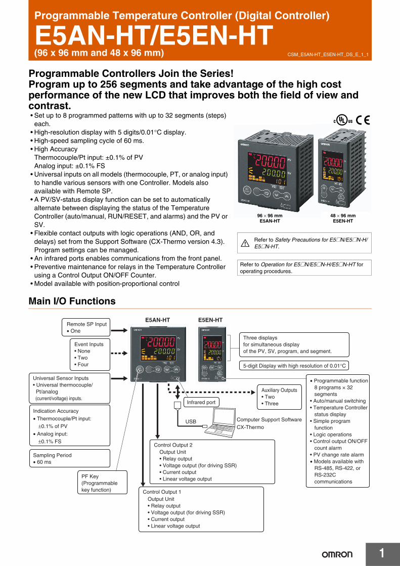
CSM_E5AN-HT_E5EN-HT_DS_E_1_1 1 Programmable Temperature Controller (Digital Controller) E5AN-HT/E5EN-HT (96 x 96 mm and 48 x 96 mm) Programmable Controllers Join the Series! Program up to 256 segments and take advantage of the high cost performance of the new LCD that improves both the field of view and contrast. • Set up to 8 programmed patterns with up to 32 segments (steps) each. • High-resolution display with 5 digits/0.01°C display. • High-speed sampling cycle of 60 ms. • High Accuracy Thermocouple/Pt input: ±0.1% of PV Analog input: ±0.1% FS • Universal inputs on all models (thermocouple, PT, or analog input) to handle various sensors with one Controller. Models also available with Remote SP. • A PV/SV-status display function can be set to automatically alternate between displaying the status of the Temperature Controller (auto/manual, RUN/RESET, and alarms) and the PV or SV. • Flexible contact outputs with logic operations (AND, OR, and delays) set from the Support Software (CX-Thermo version 4.3). Program settings can be managed. • An infrared ports enables communications from the front panel. • Preventive maintenance for relays in the Temperature Controller using a Control Output ON/OFF Counter. • Model available with position-proportional control Main I/O Functions 96 × 96 mm E5AN-HT 48 × 96 mm E5EN-HT Refer to Safety Precautions for E5@N/E5@N-H/ E5@N-HT. Refer to Operation for E5@N/E5@N-H/E5@N-HT for operating procedures. • Programmable function 8 programs × 32 segments • Auto/manual switching • Temperature Controller status display • Simple program function • Logic operations • Control output ON/OFF count alarm • PV change rate alarm • Models available with RS-485, RS-422, or RS-232C communications Event Inputs • None • Two • Four Universal Sensor Inputs • Universal thermocouple/ Pt/analog (current/voltage) inputs. Indication Accuracy • Thermocouple/Pt input: ±0.1% of PV • Analog input: ±0.1% FS Sampling Period • 60 ms PF Key (Programmable key function) Auxiliary Outputs • Two • Three Remote SP Input • One Three displays for simultaneous display of the PV, SV, program, and segment. 5-digit Display with high resolution of 0.01°C Infrared port E5AN-HT E5EN-HT Computer Support Software CX-Thermo USB Control Output 1 Output Unit • Relay output • Voltage output (for driving SSR) • Current output • Linear voltage output Control Output 2 Output Unit • Relay output • Voltage output (for driving SSR) • Current output • Linear voltage output
Transcript of E5AN-HT/E5EN-HT Programmable Temperature Controller (Digital Controller…€¦ · ·...
CSM_E5AN-HT_E5EN-HT_DS_E_1_1
1
Programmable Temperature Controller (Digital Controller)
E5AN-HT/E5EN-HT(96 x 96 mm and 48 x 96 mm)
Programmable Controllers Join the Series!Program up to 256 segments and take advantage of the high cost performance of the new LCD that improves both the field of view and contrast.• Set up to 8 programmed patterns with up to 32 segments (steps)
each.• High-resolution display with 5 digits/0.01°C display. • High-speed sampling cycle of 60 ms.• High Accuracy
Thermocouple/Pt input: ±0.1% of PVAnalog input: ±0.1% FS
• Universal inputs on all models (thermocouple, PT, or analog input) to handle various sensors with one Controller. Models also available with Remote SP.
• A PV/SV-status display function can be set to automatically alternate between displaying the status of the Temperature Controller (auto/manual, RUN/RESET, and alarms) and the PV or SV.
• Flexible contact outputs with logic operations (AND, OR, and delays) set from the Support Software (CX-Thermo version 4.3). Program settings can be managed.
• An infrared ports enables communications from the front panel.• Preventive maintenance for relays in the Temperature Controller
using a Control Output ON/OFF Counter. • Model available with position-proportional control
Main I/O Functions
96 × 96 mmE5AN-HT
48 × 96 mmE5EN-HT
Refer to Safety Precautions for E5@N/E5@N-H/E5@N-HT.
Refer to Operation for E5@N/E5@N-H/E5@N-HT for operating procedures.
• Programmable function 8 programs × 32 segments • Auto/manual switching• Temperature Controller status display• Simple program function• Logic operations• Control output ON/OFF count alarm • PV change rate alarm • Models available with RS-485, RS-422, or RS-232C communications
Event Inputs • None• Two• Four
Universal Sensor Inputs • Universal thermocouple/ Pt/analog (current/voltage) inputs.
Indication Accuracy
• Thermocouple/Pt input:
±0.1% of PV
• Analog input:
±0.1% FS
Sampling Period• 60 ms
PF Key(Programmable key function)
Auxiliary Outputs• Two• Three
Remote SP Input • One
Three displays for simultaneous display of the PV, SV, program, and segment.
5-digit Display with high resolution of 0.01°C
Infrared port
E5AN-HT E5EN-HT
Computer Support Software
CX-ThermoUSB
Control Output 1Output Unit• Relay output• Voltage output (for driving SSR)• Current output• Linear voltage output
Control Output 2Output Unit• Relay output• Voltage output (for driving SSR)• Current output• Linear voltage output

E5AN-HT/E5EN-HT
2
Lineup
Note: The Controller can be used for heating/cooling control even if only 1 control output is used.
Model Number StructureModel Number LegendControllers
1. TypeHT: Programmable
2. Control ModeBlank: Standard or heating/cooling controlP: Position-proportional control
3. Control Output 1 A: Control Output UnitR: Relay output
4. Control Output 2 A: Control Output UnitR: Relay output
5. Auxiliary Outputs2: Two outputs3: Three outputs
6. Option 1Blank: None H: Heater burnout/SSR failure/Heater overcurrent detection (CT1)HH: Heater burnout/SSR failure/Heater overcurrent detection
(CT2)
7. Option 2B: Two event inputsBF: Event input + Transfer output
8. Option 3M: Option Unit can be mounted.
9. Power Supply Voltage Blank: 100 to 240 VACD: 24 VAC/VDC
10.Case ColorBlank: Black
11.Terminal Cover -500: With Terminal Cover
Option Units
1. Function EN01: RS-232C communicationsEN02: RS-422 communicationsEN03: RS-485 communicationsAKB: Event input
Output Units
1. Control OutputR: Relay outputQ: Voltage output (for driving SSR)
Q3: Voltage output (for driving SSR) + 24 VDC (NPN)Q4: Voltage output (for driving SSR) + 24 VDC (PNP)C3: Current output + 4 to 20 mA DCC3D: Current output + 0 to 20 mA DCV34: Linear voltage output + 0 to 10 VDCV35: Linear voltage output + 0 to 5 VDC
2. VersionBlank: Available for E5AN-H/E5EN-H/E5AN-HT/E5EN-HT and
E5AK/E5EK.N: Available only for E5AN-H/E5EN-H and E5AN-HT/E5EN-HT.
Note: Estimates can be provided for coatings and other specifications that are not given in the datasheet. Ask your OMRON representative for details.
E5AN-HT/E5EN-HT Programmable Type
2 control outputs
1 control output 2 auxiliary outputs
2 auxiliary outputs
Terminal block Fully universal input
1 2 3 4 5 6 7 8 9 1110E5AN/E5EN-@@@@@@@M@-@-500
1E53-@
1 2E53-@@
This data sheet is provided as a guideline for selecting products. Be sure to refer to the following user manuals for application precautions and other information required for operation before attempting to use the product.
E5CN-HT/E5AN-HT/E5EN-HT Digital Controllers User's Manual Programmable Type (Cat. No. H169) E5CN-HT/E5AN-HT/E5EN-HT Digital Controllers Communications Manual Programmable Type (Cat. No. H170)

E5AN-HT/E5EN-HT
3
Ordering InformationE5AN-HT
E5EN-HT
Size Casecolor
Powersupplyvoltage
Controlmethod
Auxiliaryoutput Control output 1/2 Heater
burnout
Optional functionsModelEvent
inputsTransferoutput RSP
1/4 DIN 96 × 96 × 78(W × H × D)
Black
100 to240 VAC
Basic2
Control Output Unit × 2 1 2 4 to 20-mAinput E5AN-HTAA2HBM-500
Control Output Unit × 2 2 2 4 to 20-mAoutput
4 to 20-mAinput E5AN-HTAA2HHBFM-500
3 Control Output Unit × 2 2 4 to 20-mAoutput
4 to 20-mAinput E5AN-HTAA3BFM-500
Valve 2Relay outputs × 2 2 4 to 20-mA
input E5AN-HTPRR2BM-500
Relay outputs × 2 2 4 to 20-mAoutput
4 to 20-mAinput E5AN-HTPRR2BFM-500
24 VAC/VDC
Basic2
Control Output Unit × 2 1 2 4 to 20-mAinput E5AN-HTAA2HBMD-500
Control Output Unit × 2 2 2 4 to 20-mAoutput
4 to 20-mAinput E5AN-HTAA2HHBFMD-500
3 Control Output Unit × 2 2 4 to 20-mAoutput
4 to 20-mAinput E5AN-HTAA3BFMD-500
Valve 2Relay outputs × 2 2 4 to 20-mA
input E5AN-HTPRR2BMD-500
Relay outputs × 2 2 4 to 20-mAoutput
4 to 20-mAinput E5AN-HTPRR2BFMD-500
Size Casecolor
Power supplyvoltage
Controlmethod
Auxil-iary
outputControl output 1/2
Heaterburn-out
Optional FunctionsModelEvent
inputsTransferoutput RSP
1/8 DIN 48 × 96 × 78(W × H × D)
Black
100 to 240 VAC
Basic2
Control Output Unit × 2 1 2 4 to 20-mAinput E5EN-HTAA2HBM-500
Control Output Unit × 2 2 2 4 to 20-mAoutput
4 to 20-mAinput E5EN-HTAA2HHBFM-500
3 Control Output Unit × 2 2 4 to 20-mAoutput
4 to 20-mAinput E5EN-HTAA3BFM-500
Valve 2Relay outputs × 2 2 4 to 20-mA
input E5EN-HTPRR2BM-500
Relay outputs × 2 2 4 to 20-mAoutput
4 to 20-mAinput E5EN-HTPRR2BFM-500
24 VAC/VDC
Basic2
Control Output Unit × 2 1 2 4 to 20-mAinput E5EN-HTAA2HBMD-500
Control Output Unit × 2 2 2 4 to 20-mAoutput
4 to 20-mAinput
E5EN-HTAA2HHBFMD-500
3 Control Output Unit × 2 2 4 to 20-mAoutput
4 to 20-mAinput E5EN-HTAA3BFMD-500
Valve 2Relay outputs × 2 2 4 to 20-mA
input E5EN-HTPRR2BMD-500
Relay outputs × 2 2 4 to 20-mAoutput
4 to 20-mAinput E5EN-HTPRR2BFMD-500

E5AN-HT/E5EN-HT
4
Accessories (Order Separately)
USB-infrared Conversion Cable
USB-Serial Conversion Cable
Terminal Cover
Note: The Terminal Cover comes with the E5AN/E5EN-@@@-500 models.
Waterproof Packing
Note: The Waterproof Packing is included with the Controller.
Current Transformers (CTs)
CX-Thermo Support Software
Output unit Model Specifications
Relay output E53-RN SPST-NO, 250 VAC, 5 A (resistive load),
electrical life: 100,000 operations
Voltage output(for driving SSR)
E53-QN 12 VDC (PNP), max. load current: 40-mA, with short-circuit protection
E53-Q3 24 VDC (NPN), max. load current: 20-mA, with short-circuit protection
E53-Q4 24 VDC (PNP), max. load current: 20-mA, with short-circuit protection
Current output
E53-C3N 4 to 20-mA DC, load: 600 Ω max., resolution: approx. 10,000
E53-C3DN 0 to 20-mA DC, load: 600 Ω max., resolution: approx. 10,000
Linear voltage output
E53-V34N 0 to 10 VDC, load: 1 kΩ min., resolution: approx. 10,000
E53-V35N 0 to 5 VDC, load: 1 kΩ min., resolution: approx. 10,000
Model
E58-CIFIR
Model
E58-CIFQ1
Connectable models Model
E5AN-HTE53-COV16
E5EN-HT
Connectable models Model
E5AN-HT Y92S-P4
E5EN-HT Y92S-P5
Hole diameter Model
5.8 dia. E54-CT1
12.0 dia. E54-CT3
Model
EST2-2C-MV4

E5AN-HT/E5EN-HT
5
SpecificationsRatingsPower supply voltage No D in model number: 100 to 240 VAC, 50/60 Hz
D in model number: 24 VAC, 50/60 Hz; 24 VDC
Operating voltage range 85% to 110% of rated supply voltage
Power consumption 100 to 240 VAC: 12 VA24 VAC/VDC: 8.5 VA (24 VAC)/5.5 W (24 VDC)
Sensor input
Any of the following can be selected.Thermocouple: K, J, T, E, L, U, N, R, S, B, W, or PL IIPlatinum resistance thermometer: Pt100 or JPt100Current input: 4 to 20 mA or 0 to 20 mAVoltage input: 1 to 5 V, 0 to 5 V, or 0 to 10 V
Input impedance Current input: 150 Ω max., Voltage input: 1 MΩ min. (Use a 1:1 connection when connecting the ES2-HB.)
Control method ON/OFF control or 2-PID control (with auto-tuning)
Control output
Relay output
Output Unit (Install the Output Unit (sold separately).) Voltage output(for driving SSR)
Current output
Linear voltage output
Relay output for position-proportional control
Relay output: Open and close: SPST-NO, 250 VAC, 1 A (including in-rush current), electrical life: 100,000 operations min.Potentiometer input: Must be between 100 Ω and 2.5 kΩ for maximum open position.
Auxiliaryoutput
Number of outputs 2 or 3 max.
Output specifications Relay output: SPST-NO, 250 VAC, 3 A (resistive load), electrical life: 100,000 operations, minimum applicable load: 5 V, 10 mA
Event input
Number of outputs 2 or 4 (with an E53-AKB)
External contact input specifications
Contact input: ON: 1 kΩ max., OFF: 100 kΩ min.
Non-contact input: ON: Residual voltage: 1.5 V max., OFF: Leakage current: 0.1 mA max.
Current flow: Approx. 7 mA per contact
Logicoperations
Number of operations 8 max.
Operations
• Logic operation: Any of the following four patterns can be selected. The input status may be inverted. (A and B) or (C and D), (A or C) and (B or D), A or B or C or D, A and B and C and D (A, B, C, and D are four inputs.)
• Delay: ON delay or OFF delay for the results of the logic operation given above. Setting time: 0 to 9999 s or 0 to 9999 min
• Output inversion: Possible
Output One work bit per operation
Work bit assignment
Any of The following can be assigned to up to eight work bits (logic operation results): operation commands (assigned to event inputs) *, auxiliary outputs, or control outputs.* Application is possible with models that do not have event inputs by using an internal assignment.
Transferoutputs
Number of outputs 1 max. (Depends on model. Models with transfer output (F in model number)
Output specifications Current output: 4 to 20 mA DC, Load: 600 Ω max., Resolution at 4 to 20 mA: Approx. 10,000
RSPinput
Number of inputs 1
Signal type Current input: 4 to 20 mA (input impedance: 150 Ω ±10%)
Analog input scaling Scaling of signal to engineering units (EU)−19,999 to 30,000 (display: 30,000 max.)
Accuracy (±0.2% of FS) ±1 digit max.
Input sampling period 60 ms
Setting method Set digitally using keys on the front panel or by using the RSP input.
Indication method
11-segment digital display and individual indicators (7-segments displays also possible)Character height: E5AN-HT: PV: 15.8 mm, SV: 9.5 mm, MV: 6.8 mm; E5EN-HT: PV: 11.8 mm, SV: 8.1 mm, MV: 5.8 mmThree displays: PV/SV/Program number/Segment number, PV/SV/MV, or PV/SV/Remaining segment time.Number of digits: 5 for PV and SV, 4 for MV
Other functions
Manual output, heating/cooling control, loop burnout alarm, other alarm functions, heater burnout detection (including SSR failure and heater overcurrent detection), 40% AT, 100% AT, MV limiter, input digital filter, temperature input shift, run/reset, protection functions, control output ON/OFF counter, extraction of square root, MV change rate limit, PV/SV status display, automatic cooling coefficient adjustment, program control functions, etc.
Ambient operating temperature −10 to 55°C (with no condensation or icing), for 3-year warranty: −10 to 50°C
Ambient operating humidity 25% to 85%
Storage temperature −25 to 65°C (with no condensation or icing)

6
E5AN-HT/E5EN-HT
Input RangesThermocouple/Platinum Resistance Thermometer/Analog Input (Fully Universal Inputs)
Input type
Platinum resistance thermometer Thermocouple Analog input
Name Pt100 JPt100 K J T E L U N R S B W PL II
4 to 20 m
A
0 to 20 m
A
1 to 5 V
0 to 5 V
0 to 10 V
Tem
per
atu
re r
ang
e (°
C)
2300
1800
1700
1600
1500
1400
1300
1200
1100
1000
900
800
700
600
500
400
300
200
100
0
−100.0
−200.0
2300.0
Usable in the following ranges by scaling: −19999 to 32400, −1999.9 to 3240.0,−199.99 to 324.00, or−19.999 to 32.400
1800.0
1700.01700.0
1300.0 1300.0 1300.0
850.0 850.0 850.0
600.0
500.0 500.0 500.0
400.0 400.0 400.0 400.0 400.0
200.00 200.00 200.00 200.00
100.0 100.0
100.0
0.0 0.0 0.0 0.0 0.0 0.0
−50.00 −20.0 −50.00−100.0 −20.0 −50.00 −50.00 −100.0
−200.0−199.9 −199.9 −200.0 −200.0−199.9 −200.0 −200.0−199.9−200.0
Setting number 0 1 2 24 3 4 5 6 21 7 8 22 9 10 23 11 12 13 14 15 16 17 18 19 20 25 26 27 28 29
Shaded settings are the default settings.The applicable standards for the input types are as follows:K, J, T, E, N, R, S, B: JIS C 1602-1995, IEC 584-1L: Fe-CuNi, DIN 43710-1985U: Cu-CuNi, DIN 43710-1985W: W5Re/W26Re, ASTM E988-1990
JPt100: JIS C 1604-1989, JIS C 1606-1989Pt100: JIS C 1604-1997, IEC 751PL II: According to Platinel II electromotive force charts from BASF (previously
Engelhard)

7
E5AN-HT/E5EN-HT
Alarm OutputsEach alarm can be independently set to one of the following 15 alarm types. The default is 2: Upper limit. Auxiliary outputs are allocated for alarms. ON delays and OFF delays (0 to 999 s) can also be specified.
Note: For models with heater burnout, SSR failure, and heater overcurrent detection, alarm 1 will be an OR output of the alarm selected from the following alarm types and the alarms for heater burnout, SSR failure, and heater overcurrent. To output only a heater burnout alarm, SSR failure alarm, and heater overcurrent alarm for alarm 1, set the alarm type to 0 (i.e., no alarm function).
*1.With set values 1, 4 and 5, the upper and lower limit values can be set independently for each alarm type, and are expressed as “L” and “H.”
*2.Set value: 1, Upper- and lower-limit alarm
*3.Set value: 4, Upper- and lower-limit range
*4.Set value: 5, Upper- and lower-limit with standby sequenceFor Upper- and Lower-Limit Alarm Described Above• Case 1 and 2
Always OFF when the upper-limit and lower-limit hysteresis overlaps.
• Case 3: Always OFF
*5.Set value: 5, Upper- and lower-limit with standby sequenceAlways OFF when the upper-limit and lower-limit hysteresis overlaps.
*6.Displayed when there is a remote SP input. *7.Refer to the E5CN-HT/E5AN-HT/E5EN-HT Digital Controllers
User's Manual (Cat. No. H169) for information on the operation of the standby sequence.
*8.Refer to the E5CN-HT/E5AN-HT/E5EN-HT Digital Controllers User's Manual (Cat. No. H169) for information on the loop burnout alarm (LBA).
*9.Refer to the E5CN-HT/E5AN-HT/E5EN-HT Digital Controllers User's Manual (Cat. No. H169) for information on the PV change rate alarm.
Set value Alarm typeAlarm output operation
Description of functionWhen alarm value X is positive
When alarm value X is negative
0 Alarm function OFF Output OFF No alarm
1 Upper- and lower-limit *1 *2 Set the deviation in the set point by setting the alarm upper limit (H) and alarm lower limit (L).
2 Upper-limit Set the upward deviation in the set point by setting the alarm value (X).
3 Lower-limit Set the downward deviation in the set point by setting the alarm value (X).
4 Upper- and lower-limit range *1 *3 Set the deviation in the set point by setting the alarm upper limit (H) and alarm lower limit (L).
5 Upper- and lower-limit with standby sequence *1
*5
*4 A standby sequence is added to the upper- and lower-limit alarm (1). *7
6 Upper-limit with standby sequence A standby sequence is added to the upper-limit alarm (2). *7
7 Lower-limit with standby sequence A standby sequence is added to the lower-limit alarm (3). *7
8 Absolute-value upper-limit The alarm will turn ON if the process value is larger than the alarm value (X) regardless of the set point.
9 Absolute-value lower-limit The alarm will turn ON if the process value is smaller than the alarm value (X) regardless of the set point.
10 Absolute-value upper-limit with standby sequence
A standby sequence is added to the absolute-value upper-limit alarm (8). *7
11 Absolute-value lower-limit with standby sequence
A standby sequence is added to the absolute-value lower-limit alarm (9). *7
12 LBA (alarm 1 type only) --- *8
13 PV change rate alarm --- *9
14 RSP absolute value upper limit *6The alarm turns ON when the remote SP (RSP) is larger than the alarm value (X). This alarm functions in both Local SP and Remote SP Modes.
15 RSP absolute value lower limit *6The alarm turns ON when the remote SP (RSP) is smaller than the alarm value (X). This alarm functions in both Local SP and Remote SP Modes.
ONOFF
SP
L H
SP
XONOFF
SP
XONOFF
SP
XONOFF
SP
XONOFF
SP
L HONOFF
SP
L HONOFF
SP
XONOFF
SP
XONOFF
SP
XONOFF
SP
XONOFF
0
XONOFF
0
XONOFF
0
XONOFF
0
XONOFF
0
XONOFF
0
XONOFF
0
XONOFF
0
XONOFF
0
XONOFF
0
XONOFF
0
XONOFF
0
XONOFF
L H
H < 0, L > 0H < L
SP
Case 1
L H
H > 0, L < 0H > L
SP
Case 2
LHH < 0, L < 0
SP
LHH < 0, L > 0H ≥ LSP
LHH > 0, L < 0H ≤ LSP
Case 3 (Always ON)
L H
H < 0, L > 0H < L
SP
Case 1
L H
H > 0, L < 0H > L
SP
Case 2
LHH < 0, L < 0
SP
LH
H < 0, L > 0H ≥ LSP
LH
H > 0, L < 0H ≤ LSP
Case 3 (Always ON)

8
E5AN-HT/E5EN-HT
Characteristics
*1. The indication accuracy of K thermocouples in the −200 to 1300°C range, T and N thermocouples at a temperature of −100°C max., and U and L thermocouples at any temperatures is ±2°C ±1 digit max. The indication accuracy of the B thermocouple at a temperature of 400°C max. is not specified. The indication accuracy of B thermocouples in the 400 to 800°C range is ±3°C max. The indication accuracy of the R and S thermocouples at a temperature of 200°C max. is ±3°C ±1 digit max. The indication accuracy of W thermocouples is ±0.3% of PV or ±3°C, whichever is greater, ±1 digit max. The indication accuracy of PL II thermocouples is ±0.3% of PV or ±2°C, whichever is greater, ±1 digit max.
*2.Ambient temperature: −10°C to 23°C to 55°C, Voltage range: −15% to 10% of rated voltage*3.K thermocouple at −100°C max.: ±10°C max.*4.External communications (RS-232C, RS-485, or RS-422) and cable communications for the Setup Tool can be used at the same time.
Indication accuracy
Thermocouple: (±0.1% of indicated value or ±1°C, whichever is greater) ±1 digit max. *1Platinum resistance thermometer: (±0.1% of indicated value or ±0.5°C, whichever is greater) ±1 digit max.Analog input: ±0.1% FS ±1 digit max.CT input: ±5% FS ±1 digit max.Potentiometer input: ±5% FS ±1 digit max.
Transfer output accuracy ±0.3% FS max.
Influence of temperature *2
Thermocouple input (R, S, B, W, PL II): (±1% of PV or ±10°C, whichever is greater) ±1 digit max.Other thermocouple input: (±1% of PV or ±4°C, whichever is greater) ±1 digit max. *3Platinum resistance thermometer: (±1% of PV or ±2°C, whichever is greater) ±1 digit max.Analog input: (±1%FS) ±1 digit max.Influence of voltage *2
Input sampling period 60 ms
Hysteresis Temperature input: 0.1 to 3240.0°C or °F (in units of 0.1°C or °F)Analog input: 0.01% to 99.99% FS (in units of 0.01% FS)
Proportional band (P) Temperature input: 0.1 to 3240.0°C or °F (in units of 0.1°C or °F)Analog input: 0.1% to 999.9% FS (in units of 0.1% FS)
Integral time (I) 0.0 to 3240.0 s (in units of 0.1 s)
Derivative time (D) 0.0 to 3240.0 s (in units of 0.1 s)
Control period 0.5, 1 to 99 s (in units of 1 s)
Manual reset value 0.0 to 100.0% (in units of 0.1%)
Alarm setting range −19999 to 32400 (decimal point position depends on input type)
Affect of signal source resistance
Thermocouple: 0.1°C/Ω max. (100 Ω max.) Platinum resistance thermometer: 0.1°C/Ω max. (10 Ω max.)
Insulation resistance 20 MΩ min. (at 500 VDC)
Dielectric strength 2,300 VAC, 50 or 60 Hz for 1 min (between terminals with different charge)
Vibration resistance
Malfunction 10 to 55 Hz, 20 m/s2 for 10 min each in X, Y, and Z directions
Destruction 10 to 55 Hz, 0.75-mm single amplitude for 2 hrs each in X, Y, and Z directions
Shock resistance
Malfunction 100 m/s2, 3 times each in X, Y, and Z directions
Destruction 300 m/s2, 3 times each in X, Y, and Z directions
WeightE5AN-HT Controller: Approx. 310 g, Mounting Bracket: Approx. 100 g
E5EN-HT Controller: Approx. 260 g, Mounting Bracket: Approx. 100 g
Degree of protection Front panel: IP66, Rear case: IP20, Terminals: IP00
Memory protection Non-volatile memory (number of writes: 1,000,000 times)
Setup Tool CX-Thermo version 4.0 or higher
Setup Tool port
Provided on the bottom of the E5AN-HT and E5EN-HT.An E58-CIFQ1 USB-Serial Conversion Cable is required to connect the computer to the E5AN-HT and E5EN-HT.Provided on the front of the E5AN-HT and E5EN-HT. An E58-CIFIR USB-infrared Conversion Cable is required to connect the computer to the E5AN-HT or E5EN-HT. *4
Standards
Approvedstandards UL 61010-1, CSA C22.2 No. 1010-1
Conformed standards EN 61010-1 (IEC 61010-1): Pollution level 2, overcurrent category II
EMC
EMI: EN 61326Radiated Interference Electromagnetic Field Strength: EN 55011 Group 1, class ANoise Terminal Voltage: EN 55011 Group 1, class AEMS: EN 61326ESD Immunity: EN 61000-4-2Electromagnetic Field Immunity: EN 61000-4-3Burst Noise Immunity: EN 61000-4-4Conducted Disturbance Immunity: EN 61000-4-6Surge Immunity: EN 61000-4-5Power Frequency Magnetic Field Immunity: EN 61000-4-8Voltage Dip/Interrupting Immunity: EN 61000-4-11

9
E5AN-HT/E5EN-HT
Program ControlNumber of programs (patterns) 8
Number of segments (steps) 32
Segment setting methodTime setting (Segment set with set point and time.)
Gradient setting (Segment type with set point, gradient, and time.)
Segment times0 h 0 min to 99 h 59 min
0 min 0 s to 99 min 59 s
Alarm setting Set separately for each program.
Reset operation Select either stopping control or fixed SP operation.
Startup operation Select continuing, resetting, manual operation, or run mode.
PID setsNumber of sets 8
Setting method Set separately for each program (automatic PID group selection also supported).
Alarm SP function Select from ramp SP and target SP.
Program status controlSegment operation Advance, hold
Program operation Program repetitions and program links
Wait operationWait method Waiting at segment ends
Wait width setting Same wait width setting for all programs
Time signals
Number of outputs 2
Number of ON/OFF Operations 1 each per output
Setting method Set separately for each program.
Program status output Program end output (pulse width can be set), run output, stage output
Program startup operation
PV start Select from segment 1 set point, slope-priority PV start
Standby0 h 0 min to 99 h 59 min
0 day 0 h to 99 day 23h
Operation end operation Select from resetting, continuing control at final set point, and fixed SP control.
Program SP shift Same program SP shift for all programs
E5AN-HT/E5EN-HT
10
USB-Serial Conversion Cable
Note: A driver must be installed in the personal computer. Refer to installation information in the operation manual for the Conversion Cable.
Communications Specifications
* The baud rate, data bit length, stop bit length, and vertical parity can be individually set using the Communications Setting Level.
Current Transformer (Order Separately) Ratings
USB-Infrared Conversion Cable
Note: A driver must be installed in the personal computer. Refer to installation information in the operation manual for the Conversion Cable.
Heater Burnout Alarms, SSR Failure Alarms, and Heater Overcurrent Alarms
*1. For heater burnout alarms, the heater current will be measured when the control output is ON, and the output assigned to the alarm 1 function will turn ON if the heater current is lower than the set value (i.e., heater burnout detection current value).
*2. For SSR failure alarms, the heater current will be measured when the control output is OFF, and the output assigned to the alarm 1 function will turn ON if the heater current is higher than the set value (i.e., SSR failure detection current value).
*3. For heater overcurrent alarms, the heater current will be measured when the control output is ON, and the output assigned to the alarm 1 function will turn ON if the heater current is higher than the set value (i.e., heater overcurrent detection current value).
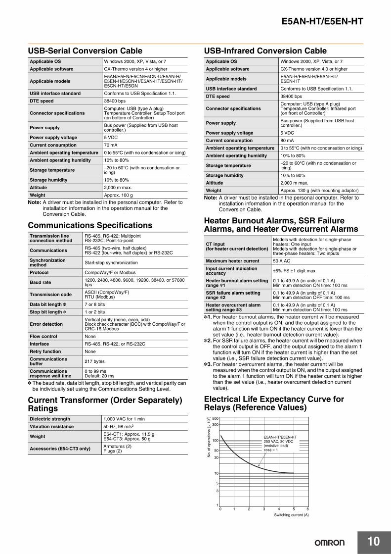
Electrical Life Expectancy Curve for Relays (Reference Values)
Applicable OS Windows 2000, XP, Vista, or 7
Applicable software CX-Thermo version 4 or higher
Applicable modelsE5AN/E5EN/E5CN/E5CN-U/E5AN-H/E5EN-H/E5CN-H/E5AN-HT/E5EN-HT/E5CN-HT/E5GN
USB interface standard Conforms to USB Specification 1.1.
DTE speed 38400 bps
Connector specificationsComputer: USB (type A plug)Temperature Controller: Setup Tool port (on bottom of Controller)
Power supply Bus power (Supplied from USB host controller.)
Power supply voltage 5 VDC
Current consumption 70 mA
Ambient operating temperature 0 to 55°C (with no condensation or icing)
Ambient operating humidity 10% to 80%
Storage temperature −20 to 60°C (with no condensation or icing)
Storage humidity 10% to 80%
Altitude 2,000 m max.
Weight Approx. 100 g
Transmission line connection method
RS-485, RS-422: MultipointRS-232C: Point-to-point
Communications RS-485 (two-wire, half duplex)RS-422 (four-wire, half duplex) or RS-232C
Synchronization method Start-stop synchronization
Protocol CompoWay/F or Modbus
Baud rate 1200, 2400, 4800, 9600, 19200, 38400, or 57600 bps
Transmission code ASCII (CompoWay/F) RTU (Modbus)
Data bit length * 7 or 8 bits
Stop bit length * 1 or 2 bits
Error detectionVertical parity (none, even, odd)Block check character (BCC) with CompoWay/F or CRC-16 Modbus
Flow control None
Interface RS-485, RS-422, or RS-232C
Retry function None
Communications buffer 217 bytes
Communications response wait time
0 to 99 msDefault: 20 ms
Dielectric strength 1,000 VAC for 1 min
Vibration resistance 50 Hz, 98 m/s2
Weight E54-CT1: Approx. 11.5 g, E54-CT3: Approx. 50 g
Accessories (E54-CT3 only) Armatures (2)Plugs (2)
Applicable OS Windows 2000, XP, Vista, or 7
Applicable software CX-Thermo version 4.0 or higher
Applicable models E5AN-H/E5EN-H/E5AN-HT/E5EN-HT
USB interface standard Conforms to USB Specification 1.1.
DTE speed 38400 bps
Connector specificationsComputer: USB (type A plug)Temperature Controller: Infrared port (on front of Controller)
Power supply Bus power (Supplied from USB host controller.)
Power supply voltage 5 VDC
Current consumption 80 mA
Ambient operating temperature 0 to 55°C (with no condensation or icing)
Ambient operating humidity 10% to 80%
Storage temperature −20 to 60°C (with no condensation or icing)
Storage humidity 10% to 80%
Altitude 2,000 m max.
Weight Approx. 130 g (with mounting adaptor)
CT input(for heater current detection)
Models with detection for single-phase heaters: One input Models with detection for single-phase or three-phase heaters: Two inputs
Maximum heater current 50 A AC
Input current indication accuracy ±5% FS ±1 digit max.
Heater burnout alarm setting range *1
0.1 to 49.9 A (in units of 0.1 A)Minimum detection ON time: 100 ms
SSR failure alarm setting range *2
0.1 to 49.9 A (in units of 0.1 A)Minimum detection OFF time: 100 ms
Heater overcurrent alarm setting range *3
0.1 to 49.9 A (in units of 0.1 A)Minimum detection ON time: 100 ms
500
300
100
50
30
10
5
3
10 1 2 3 4 5 6
E5AN-HT/E5EN-HT250 VAC, 30 VDC (resistive load)cosφ = 1
Switching current (A)
No.
of o
pera
tions
(×
104 )

E5AN-HT/E5EN-HT
11
External ConnectionsControl output 1 and control output 2 are functionally isolated from the internal circuits.
Note: Wire all voltage input terminals correctly. The Controller may fail if voltage input terminals are wired incorrectly.
Potentiometer
RDB
RDA
SG
SDB
SDA
4 to 20 mA DC(Load: 600 Ω max.)
4 to 20 mA DC
1
2
3
4
5
6
7
8
9
10
21
22
23
24
25
26
27
28
29
30
21
22
23
24
25
26
27
28
29
30
11
12
13
14
15
16
17
18
19
20
• 100 to 240 VAC• 24 VAC/VDC (no polarity)
Input power supply
Control output 1
B
VmA
Control output 2 CT2
CT1
EV1EV2
CT2
DO NOTUSE
DO NOTUSE
DO NOTUSE
B
A
C
W
O
DO NOTUSE
DO NOTUSE
DO NOTUSE
DO NOTUSE
Event Inputs *
EV1EV2
Event Inputs
Communications
B (+)
A (−)
DO NOT USE
B (+)
A (−)
11
12
13
21
22
E53-EN03RS-485
11
12
13
21
22
E53-EN01RS-232C
SD
RD
SG
DO NOT USE
DO NOT USE
11
12
13
21
22
E53-AKB
11
12
13
21
22
E53-EN02RS-422
Control Output UnitControl outputs 1, 2Refer to page 4
Models with Position-proportional ControlRelay output250 VAC, 1 A(including inrushcurrent)
Control outputs 1, 2
Relay outputSPST-NO,250 VAC, 3 A(resistive load)
Auxiliary outputs 1, 2, 3
A heater burnout alarm, SSR failure, heater overcurrent alarm, input alarm, or Remote SP Input Error is sent to the output to which the alarm 1 function is assigned.
Auxiliary output 3
* EV3 and EV4 are assigned to event inputs in controllers with two event inputs.
14
15
16
1
2
3
4
5
6
7
8
9
10
21
22
23
24
25
26
27
28
29
30
EV4
EV3
+
−+
−
+
−+
−
Output unit
Output unit
Control Output Unit
1
2
3
4
5
6
7
8
9
10
Open
Closed
Models with Position-proportional Control
Event input */Transfer output/Remote SP
Remote SP input
DO NOT USE
Transfer output
Input power supply
Input power supply
Auxiliary output 2
Auxiliary output 1
Auxiliary output 2
Auxiliary output 1
Auxiliary output 2
Auxiliary output 1
Relay outputSPDT, 250 VAC, 3 A(resistive load)
Auxiliary output 3
The Temperature Controller is set for a K-type thermocouple (input type = 5) by default. An input error (s.err) will occur if the input type setting does not agree with the temperature sensor. Check the input type.
Option UnitsControllers

12
E5AN-HT/E5EN-HT
Nomenclature
Dimensions (Unit: mm)
Infrared communications reception port
Operation indicatorsNo.1 display
No.2 display
No.3 display
Up Key
Down Key
Temperature unit
Mode KeyLevel Key
Programmable Function Key/ Auto/Manual Key
E5AN-HT E5EN-HT
Infrared communications reception port
Operation indicators
Temperature unit
Operation indicators
Mode Key
Level Key
No.1 display
No.2 display
No.3 display
Up Key
Down Key
Programmable Function Key/Auto/Manual Key
Mounting Bracket(Accessory)
WaterproofPacking(Accessory)
Terminal Cover(E53-COV16)(Accessory)
Crimp terminal size: M3.5
96 × 96 112 91
79.26
2
92+0.8 0
92+0.8 0
92+0.8 0 (96 × number of units − 3.5)+1.0
0
120 min. Group mounting does notallow waterproofing.
Mounted Separately Group Mounted *
• Recommended panel thickness is 1 to 8 mm.
• Group mounting is not possible in the vertical direction. (Maintain the specified mounting space between Controllers.)
• To mount the Controller so that it is waterproof, insert the waterproof packing onto the Controller.
• When two or more Controllers are mounted, make sure that the surrounding temperature does not exceed the allowable operating temperature specified in the specifications.
E5AN-HT
*Group mounting is not possible if an E53-C3N or E53-C3DN Output Unit is used for control output 1 or 2. For these combinations, maintain the following mounting space between Controllers.
92+0.8 0
92+0.8 0
110 min.
120 min.

E5AN-HT/E5EN-HT
13
Mounting Bracket(Accessory)
WaterproofPacking(Accessory)
Terminal Cover(E53-COV16)(Accessory)
Crimp terminal size: M3.5
96 112
48
79.26
91
2
E5EN-HT
92+0.8 0
92+0.8 0
45+0.6 0
120 min.
(48 × number of units − 2.5)+1.0 0
Group mounting does notallow waterproofing.
Mounted Separately Group Mounted *
• Recommended panel thickness is 1 to 8 mm.• Group mounting is not possible in the vertical direction.
(Maintain the specified mounting space between Controllers.)
• When two or more Controllers are mounted, make sure that the surrounding temperature does not exceed the allowable operating temperature specified in the specifications.
*Group mounting is not possible if an E53-C3N or E53-C3DN Output Unit is used for control output 1 or 2. For these combinations, maintain the following mounting space between Controllers.
45+0.6 0
60 min.
120 min.
92+0.8 0

E5AN-HT/E5EN-HT
14
Accessories (Order Separately)
(2,000) 54
4.6 dia.
35.8
17.8
USB connector (type A plug)
LED indicator: RD LED indicator: SD
USB-Infrared Conversion CableE58-CIFIRUSB-Infrared Conversion Cable
16
99.2
18.5
23.1
(75)21.8
39
Mounting Adapter(Accessory)
With Mounting Adapter Connected
Mounting Adapter
(2,100)
250 1,765
USB connector (type A plug) Serial connectorLED indicator: RD
LED indicator: SD
USB-Serial Conversion CableE58-CIFQ1
Terminal CoversE53-COV16 (Six Covers provided.)
10
1.2 3.2
44.8

E5AN-HT/E5EN-HT
15
Current Transformers
Waterproof PackingY92S-P4 (for DIN 96 × 96) Order the Waterproof Packing separately if it becomes lost or
damaged.The Waterproof Packing can be used to achieve an IP66 degree of protection.(Deterioration, shrinking, or hardening of the waterproof packing may occur depending on the operating environment. Therefore, periodic replacement is recommended to ensure the level of waterproofing specified in IP66. The time for periodic replacement depends on the operating environment. Be sure to confirm this point at your site. Consider one year a rough standard. OMRON shall not be liable for the level of water resistance if the customer does not perform periodic replacement.)The Waterproof Packing does not need to be attached if a waterproof structure is not required.
Y92S-P5 (for DIN 48 × 96)
E54-CT3 Accessory• Armature
30
21
155.8 dia.
25 3
40
10.5
2.8
7.5
10
Two, 3.5 dia.
40 × 40
30
12 dia.
9
2.36 dia.
15
30
Two, M3 (depth 4)
Approx. 3 dia.
18
(22)
Approx. 6 dia.
PlugArmature
Lead
E54-CT1
E54-CT3
Connection Example
• Plug
E54-CT1Thru-current (Io) vs. Output Voltage (Eo) (Reference Values)Maximum continuous heater current: 50 A (50/60 Hz)Number of windings: 400±2Winding resistance: 18±2 Ω
Thru-current (Io) A (r.m.s.)
1 10 100 mA 1 10 100 1,000 A
Out
put v
olta
ge (
Eo)
V (
r.m.s
.) 100 V 50 Hz
Distortionfactor 10%
3%1%
100 Ω
RL = 10 Ω
∞10
1
100 mV
10
1
100 µV
10
1 kΩ
E54-CT3Thru-current (Io) vs. Output Voltage (Eo) (Reference Values)Maximum continuous heater current: 120 A (50/60 Hz)(Maximum continuous heater current for an OMRON Temperature Controller is 50 A.)Number of windings: 400±2Winding resistance: 8±0.8 Ω
3%1%
1 kΩ
100 Ω50 Ω
RL = 10 Ω
500 Ω
∞Distor-tionfactor 10%
Thru-current (Io) A (r.m.s.)
1 10 100 mA 1 10 100 1,000 A
Out
put v
olta
ge (
Eo)
V (
r.m.s
.) 100 V 50 Hz
10
1
100 mV
10
1
100 µV
10