
E5CK Digital Controller - Omronomron.com.ru/dynamic/managers/manage_13/files/H079EN106.pdf ·...
24
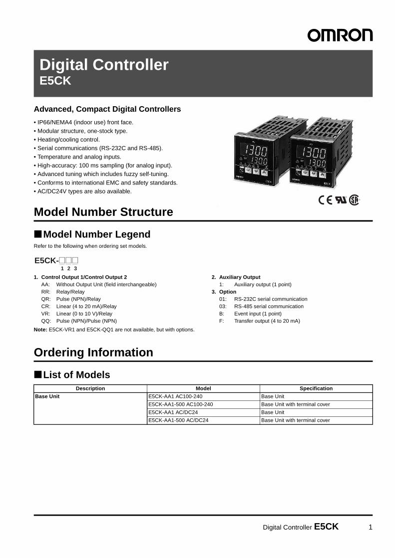
Digital Controller E5CK 1 Digital Controller E5CK Advanced, Compact Digital Controllers • IP66/NEMA4 (indoor use) front face. • Modular structure, one-stock type. • Heating/cooling control. • Serial communications (RS-232C and RS-485). • Temperature and analog inputs. • High-accuracy: 100 ms sampling (for analog input). • Advanced tuning which includes fuzzy self-tuning. • Conforms to international EMC and safety standards. • AC/DC24V types are also available. ® Model Number Structure ■ Model Number Legend Refer to the following when ordering set models. 1. Control Output 1/Control Output 2 AA: Without Output Unit (field interchangeable) RR: Relay/Relay QR: Pulse (NPN)/Relay CR: Linear (4 to 20 mA)/Relay VR: Linear (0 to 10 V)/Relay QQ: Pulse (NPN)/Pulse (NPN) 2. Auxiliary Output 1: Auxiliary output (1 point) 3. Option 01: RS-232C serial communication 03: RS-485 serial communication B: Event input (1 point) F: Transfer output (4 to 20 mA) Note: E5CK-VR1 and E5CK-QQ1 are not available, but with options. Ordering Information ■ List of Models 1 2 3 E5CK-@@@ Description Model Specification Base Unit E5CK-AA1 AC100-240 Base Unit E5CK-AA1-500 AC100-240 Base Unit with terminal cover E5CK-AA1 AC/DC24 Base Unit E5CK-AA1-500 AC/DC24 Base Unit with terminal cover
Transcript of E5CK Digital Controller - Omronomron.com.ru/dynamic/managers/manage_13/files/H079EN106.pdf ·...
Digital Controller E5CK 1
Digital ControllerE5CK
Advanced, Compact Digital Controllers
• IP66/NEMA4 (indoor use) front face.
• Modular structure, one-stock type.• Heating/cooling control.• Serial communications (RS-232C and RS-485).
• Temperature and analog inputs.• High-accuracy: 100 ms sampling (for analog input).• Advanced tuning which includes fuzzy self-tuning.
• Conforms to international EMC and safety standards.• AC/DC24V types are also available.
®
Model Number Structure
Model Number LegendRefer to the following when ordering set models.
1. Control Output 1/Control Output 2AA: Without Output Unit (field interchangeable)RR: Relay/RelayQR: Pulse (NPN)/RelayCR: Linear (4 to 20 mA)/RelayVR: Linear (0 to 10 V)/RelayQQ: Pulse (NPN)/Pulse (NPN)
2. Auxiliary Output1: Auxiliary output (1 point)
3. Option01: RS-232C serial communication03: RS-485 serial communicationB: Event input (1 point)F: Transfer output (4 to 20 mA)
Note: E5CK-VR1 and E5CK-QQ1 are not available, but with options.
Ordering Information
List of Models
1 2 3E5CK-@@@
Description Model Specification
Base Unit E5CK-AA1 AC100-240 Base Unit
E5CK-AA1-500 AC100-240 Base Unit with terminal cover
E5CK-AA1 AC/DC24 Base Unit
E5CK-AA1-500 AC/DC24 Base Unit with terminal cover

2 Digital Controller E5CK
Note: A single Output Unit and Option Unit can be mounted to each Base Unit.
Inspection ReportThe Digital Controller can be provided together with an inspection report.
Refer to the following legend with the suffix “K” when ordering a model provided together with an inspection report.E5CK-AA1-K, E53-CKF-K
Accessories (Order Separately)
Specifications
Ratings
Input Ranges
Platinum Resistance Thermometer
Description Model Specification
Output Unit E53-R4R4 Relay/Relay
E53-Q4R4 Pulse (NPN)/Relay
E53-Q4HR4 Pulse (PNP)/Relay
E53-C4R4 Linear (4 to 20 mA)/Relay
E53-C4DR4 Linear (0 to 20 mA)/Relay
E53-V44R4 Linear (0 to 10 V)/Relay
E53-Q4Q4 Pulse (NPN)/Pulse (NPN)
E53-Q4HQ4H Pulse (PNP)/Pulse (PNP)
Description Model Specification
Option Unit E53-CK01 RS-232C
E53-CK03 RS-485
E53-CKB Event input: 1 point
E53-CKF Transfer output (4 to 20 mA)
Name Model
Terminal Cover E53-COV07
Item AC100-240V type AC/DC24V type
Supply voltage AC100 to 240V, 50/60 Hz AC/DC24V, 50/60 Hz
Power consumption 15 VA 6 VA, 3.5 W
Operating voltage range 85% to 110% of rated supply voltage
Input Thermocouple: K, J, T, E, L, U, N, R, S, B, W, PLIIPlatinum resistance thermometer: JPt100, Pt100Current input: 4 to 20 mA, 0 to 20 mAVoltage input: 1 to 5 V, 0 to 5 V, 1 to 10 V
Input impedance Current input: 150 ΩVoltage input: 1 MΩ min.
Control output According to Output Unit (see “Output Unit Ratings and Characteristics”)
Auxiliary output SPST-NO, 1 A at 250 VAC (resistive load)
Control method ON/OFF or 2-PID control (with auto-tuning)
Setting method Digital setting using front panel keys
Indication method 7-segment digital display and LEDs
Other functions According to Option Unit (see “Option Unit Ratings and Characteristics”)
Input (switch selectable) JPt100 Pt100
Range °C −199.9 to 650.0 −199.9 to 650.0
°F −199.9 to 999.9 −199.9 to 999.9
Resolution (°C/°F) (main setting and alarm)
0 1

Digital Controller E5CK 3
Thermocouple
Note: Setting number is factory-set to 2 (K1).Thermocouple W is W/Re 5-26 (tungsten rhenium 5, tungsten rhenium 26).
Current/Voltage
Input (switch selectable) (see note)
K1 K2 J1 J2 T E L1 L2 U N R S B W PLII
Range °C −200 to 1,300
0.0 to 500.0
−100 to 850
0.0 to 400.0
−199.9 to 400.0
0 to 600
−100 to 850
0.0 to 400.0
−199.9 to 400.0
−200 to 1,300
0 to 1,700
0 to 1,700
100 to 1,800
0 to 2,300
0 to 1,300
°F −300 to 2,300
0.0 to 900.0
−100 to 1,500
0.0 to 750.0
−199.9 to 700.0
0 to 1,100
−100 to 1,500
0.0 to 750.0
−199.9 to 700.0
−300 to 2,300
0 to 3,000
0 to 3,000
300 to 3,200
0 to 4,100
0 to 2,300
Resolution (°C/°F) (main setting and alarm)
2 3 4 5 6 7 8 9 10 11 12 13 14 15 16
Input (switch selectable) Current input Voltage input
4 to 20 mA 0 to 20 mA 1 to 5 V 0 to 5 V 0 to 10 V
Range One of following ranges depending on results of scaling−1999 to 9999−199.9 to 999.9−19.99 to 99.99−1.999 to 9.999
Resolution (°C/°F) (main setting and alarm)
17 18 19 20 21

4 Digital Controller E5CK
Characteristics
Note: The indication accuracy of the K1, T, and N thermocouples at a temperature of −100°C or less is ±2°C ±1 digit maximum. The indicationaccuracy of the U, L1, and L2 thermocouples at any temperature is ±2°C ±1 digit maximum.The indication accuracy of the B thermocouple at a temperature of 400°C or less is unrestricted.The indication accuracy of the R and S thermocouples at a temperature of 200°C or less is ±3°C ±1 digit maximum.The indication accuracy of the W thermocouple at any temperature is (±0.3% of the indicated value or ±3°C, whichever is greater) ±1 digitmaximum.The indication accuracy of the PLII thermocouple at any temperature is (±0.3% or ±2°C, whichever is greater) ±1 digit maximum.
Indication accuracy (see note) Thermocouple:(±0.3% of indication value or ±1°C, whichever greater) ±1 digit max.Platinum resistance thermometer:(±0.2% of indication value or ±0.8°C, whichever greater) ±1 digit max.Analog input: ±0.2% FS ±1 digit max.
Hysteresis 0.01% to 99.99% FS (in units of 0.01% FS)
Proportional band (P) 0.1% to 999.9% FS (in units of 0.1% FS)
Integral (reset) time (I) 0 to 3,999 s (in units of 1 s)
Derivative (rate) time (D) 0 to 3,999 s (in units of 1 s)
Control period 1 to 99 s (in units of 1 s)
Manual reset value 0.0% to 100.0% (in units of 0.1%)
Alarm setting range −1,999 to 9,999 or −199.9 or 999.9 (decimal point position dependent on input type)
Sampling period Temperature input: 250 msCurrent/voltage input: 100 ms
Insulation resistance 20 MΩ min. (at 500 VDC)
Dielectric strength 2,000 VAC, 50/60 Hz for 1 min between terminals of different polarities
Vibration resistance Malfunction: 10 to 55 Hz, 10 m/s2 (approx. 1G) for 10 min each in X, Y, and Z directionsDestruction: 10 to 55 Hz, 20 m/s2 (approx. 2G) for 2 hrs each in X, Y, and Z directions
Shock resistance Malfunction: 200 m/s2 min. (approx. 20G), 3 times each in 6 directions(100 m/s2 (approx. 10G) applied to the relay)
Destruction: 300 m/s2 min. (30G), 3 times each in 6 directions
Ambient temperature Operating: −10°C to 55°C (with no icing)/3-year warranty period: –10°C to 50°CStorage: −25°C to 65°C (with no icing)
Ambient humidity Operating: 35% to 85%
Degree of protection Front panel: NEMA4 for indoor use (equivalent to IP66)Rear case: IEC standard IP20Terminals: IEC standard IP00
Memory protection Non-volatile memory (number of writings: 100,000 operations)
Weight Approx. 170 g;Adapter: approx. 10 g
EMC Emission Enclosure: EN55011 Group 1 class AEmission AC Mains: EN55011 Group 1 class AImmunity ESD: EN61000-4-2: 4 kV contact discharge (level 2)
8 kV air discharge (level 3)Immunity RF-interference: ENV50140: 10 V/m (amplitude modulated, 80 MHz to 1 GHz)
(level 3)10 V/m (pulse modulated, 900 MHz)
Immunity Conducted Disturbance: ENV50141: 10 V (0.15 to 80 MHz) (level 3)Immunity Burst: EN61000-4-4: 2 kV power-line (level 3)
2 kV I/O signal-line (level 4)
Approved standards UL1092, CSA22.2 No. 142, CSA22.2 No. 1010-1Conforms to EN50081-2, EN50082-2, EN61010-1 (IEC1010-1)Conforms to VDE0106/part 100 (Finger Protection), when the separately-ordered terminal cover is mounted.

Digital Controller E5CK 5
Output Unit Ratings and Characteristics
Option Unit Ratings and Characteristics
Relay output SPST, 250 VAC, 3 A (resistive load)Mechanical life expectancy: 10,000,000 operations min.Electrical life expectancy: 100,000 operations min.
Voltage output NPN: 20 mA at 12 VDC (with short-circuit protection)PNP: 20 mA at 12 VDC (with short-circuit protection)
Linear voltage output 0 to 10 VDC:Permissible load impedance: 1 kΩ min.Resolution: approx. 2,600
Linear current output 4 to 20 mA:Permissible load impedance: 500 Ω max.Resolution: approx. 2,600
Event inputs Contact input:ON: 1 kΩ max., OFF: 100 kΩ min.No-contact input:ON: residual voltage 1.5 V max., OFF: leakage current 0.1 mA max.
Communications Interface: RS-232C or RS-485Transmission method: Half-duplexSynchronization method: Start-stop synchronization (asynchronous method)Baud rate: 1.2/2.4/4.8/9.6/19.2 kbpsTransmission code: ASCII
Transfer output 4 to 20 mA:Permissible load impedance: 500 Ω max.Resolution: approx. 2,600

6 Digital Controller E5CK
Nomenclature
DimensionsNote: All units are in millimeters unless otherwise indicated.
Operation Indicators
A/M Key
No. 1 Display
No. 2 Display
Up Key/Down Key
Display Key
• OUT1 Lights when the pulse output function assigned to control output 1 turns ON.
• OUT2 Lights when the pulse output function assigned to control output 2 turns ON.
• SUB1 Lights when the output func-tion assigned to auxiliary output 1 turns ON.
• MANU Lights when the manual op-eration mode.
• STOP Lights during operation has stopped.
• RMT Lights during remote opera-tion.
• AT Flashes during auto-tuning.
Press to select the auto operation or manual operation.
Press for less than 1 s to shift the display to the next parameter. When this key is pressed for 1 s or more, the menu screen will be displayed in any case.
Press to increase or decrease the value on the No.2 display.
Displays the set point, set point dur-ing SP ramp, manipulated variable, or parameter settings.
Displays the process value or pa-rameter symbols.
5853 x 53 13 100
44.8
x 4
4.8
48
45+0.6 0
45+0.6 0
E5CK
Panel Cutouts65 min.
60 min.
Note: 1. Recommended panel thickness is 1 to 5 mm. 2. Maintain the specified vertical and horizontal mount-
ing space between each Unit. Units must not be closely mounted vertically or horizontally.

Digital Controller E5CK 7
Installation
Installation
Main Parts
Draw-outFirst, draw out the internal mechanism from the housing.Pull out the internal mechanism while pressing the hooks on the leftand right sides of the front panel.
Setting Up the Output Unit1. Two rectangular holes are provided on the power board (right side
of Controller). Fit the two protrusions of the Output Unit into thesetwo holes.
2. With the Output Unit fitted into the power board, fit the Output Unitinto the connector on the control board (left side of Controller).
Setting Up the Option Unit1. Place the Controller with its bottom facing up, and fit the board
horizontally into the Connector on the power board (right side ofcontroller).
2. With the power board connected, fit the board vertically into theConnector on the control board (left side of controller).
Terminals
Output Unit
Rear case
Front panel
Option Unit
Input type jump-er connector
1
2
1
2

8 Digital Controller E5CK
Mounting1. Insert the E5CK Controller into the panel’s mounting hole at the
position shown in the figure below.2. Push the adapter along the Controller body from the terminals up
to the panel, and fasten temporarily.3. Tighten the two fixing screws on the adapter. When tightening
screws, tighten the two screws alternately keeping the torque toapproximately 0.29 to 0.39 N·m, or 3 to 4 kgf·cm.
Terminal CoverThe E5CK-AA1-500 Controller is provided with a Terminal Cover(E53-COV07). Fasten the Terminal Cover as follows by using thesnap pin.
Adapter
Panel
Watertight packing

Digital Controller E5CK 9
WiringTerminal Arrangement
PrecautionsUse ducts to separate input leads and power lines in order to protectthe Controller and its lines from external noise.
Solderless terminals are recommended when wiring the Controller.
Tighten the terminal screws using a torque no greater than 0.78 N·m,or 8 kgf·cm max. Take care not to tighten the terminal screws tootightly.
Power BlocksThe E5CK has independent power supplies for each of the terminalblocks shown below. However, note that the power supplies forblocks C (exclude relay output) and D are shared for the followingoption unit.
• Option unit: E53-CKB or E53-CKF
WiringPower SupplyInput 100 to 240 VAC or AC/DC 24 V to terminal numbers 4 and 5 according to the specification.
InputConnect the input to terminal numbers 6 to 8 as follows according to the input type.
Match the inputs with the internal jumper settings for each input type. For thermocouple or platinum resistance thermometer inputs, set the inputsto a common position (TC/PT) as the temperature input.
Control OutputTerminal numbers 11 and 12 are for control output 1 (OUT1). The five output types and internal equalizing circuits are available according to theOutput Unit.
5
4
3
2
1
10
9
8
7
613 14
11 12
AC100−240V~ (AC/DC24V~)
OUT1
OUT2
SUB1
OPTION
IN
SOURCE
A C54321
109876
C
D B
11 12
13 14
5
4
3
2
1
10
9
8
7
613 14
11 12
8
7
6
8
7
6
8
7
6
8
7
6
−
+
−
+
−
+
V mA
TC⋅PT V I
5
4
3
2
1
10
9
8
7
613 14
11 12
Thermocouple Voltage input Current inputPlatinum resistance thermometer
5
4
3
2
1
10
9
8
7
613 14
11 12 11
12
11
12
L
11
12
L
11
12
L
11
12
L
+v+ + + +
mAV
+v
E53-R4R4 E53-V44R4
NPN PNP 0 to 10 V 4 to 20mA
GND
Relay
GND
E53-Q4R4 E53-Q4Q4
E53-Q4HR4 E53-Q4HQ4H
E53-C4R4 E53-C4DR4
− − − −

10 Digital Controller E5CK
Terminal numbers 9 and 10 are for control output 2 (OUT2). The three output types and internal equalizing circuits are available according to theOutput Unit.
The following table shows the specifications for each output type.
Auxiliary Output 1Terminal numbers 2 and 3 are for auxiliary output 1 (SUB1).
The internal equalizing circuit for auxiliary output 1 is as follows:
Relay specifications are as follows:SPST-NO, 250 VAC, 1 A
OptionTerminal numbers 1, 13, and 14 are valid only when the Option Unit is set in the Controller.
The following four connections are possible depending on the model of the Option Unit.
Use event inputs under the following conditions:
The polarity for no-contact input is as follows:
Transfer output specifications are as follows:4 to 20 mA, load: 500 Ω max., resolution approx. 2600
10
9
10
9
L
10
9
L
+V+
−
+
−
+V
GND
E53-Q4Q4 E53-Q4HQ4H
NPN PNPRelay
GND
E53-R4R4/E53-V44R4 E53-Q4R4/E53-C4R4 E53-Q4HR4/E53-C4DR4
Output type Specifications
RelayVoltage (NPN)Voltage (PNP)
3 A at 250 VAC20 mA at 12 VDC (with short-circuit protection)20 mA at 12 VDC (with short-circuit protection)
0 to 10 V4 to 20 mA
0 to 10 VDC, permissible load impedance: 1 kΩ min., resolution: approx. 2,6004 to 20 mA, permissible load impedance: 500 Ω max., resolution: approx. 2,600
5
4
3
2
1
10
9
8
7
613 14
11 12 3
2
Contact input ON: 1 kΩ max., OFF: 100 kΩ min.
No-contact input ON: residual voltage 1.5 V max., OFF: leakage current 0.1 mA max.
5
4
3
2
1
10
9
8
7
613 14
11 12 13
14
1
13
14
1
13
14
1
13
14
1
A
B
+
−
SD
RD
SG
4 to 20mA
E53-CK01
RS-232C
E53-CK03
RS-485
E53-CKB E53-CKF
Event input Transfer output
13
14
1
+
−

Digital Controller E5CK 11
Operation
Parameter Operation ListSwitching to modes other than manual or protect mode is carried out using mode selection in the menu display.
The figure below shows all parameters in the order that they are displayed. Some parameters are not displayed depending on the protect modesetting and conditions of use.
Parameters and MenusNote: For more details on the functions of each part and display contents, refer to the E5CK User’s Manual (H78).
Protect Mode Limits use of the menu and A/M Keys. The protect function prevents unwanted modification of parameters andswitching between the auto and manual operation.
Manual Mode The Controller can be switched to manual operation. The manipulated variable can be manipulated manually onlyin this mode.
Level 0 Mode Set the Controller to this mode during normal operation. In this mode, change the set point during operation, andstart or stop Controller operation. The process value, SP ramp, and manipulated variable can only be monitoredin this mode.
Level 1 Mode The main mode for adjusting control. In this mode, execute AT (auto-tuning), and set alarm values, the control pe-riod, and PID parameters.
Level 2 Mode The auxiliary mode for adjusting control. In this mode, set the parameters for limiting the manipulated variable andset point, switch between the remote and local modes, and set the loop break alarm (LBA), alarm hysteresis, andthe digital filter value of inputs.
Setup Mode The mode for setting the basic specifications. In this mode, set parameters that must be checked or set beforeoperation such as the input type, scaling, output assignments and direct/reverse operation.
Expansion Mode The mode for setting expanded functions. In this mode, set ST (self-tuning), SP setting limiter, select advancedPID or ON/OFF control, specify the standby sequence resetting method, initialize parameters, and set the time forautomatic return to the monitoring display.
Option Mode The mode for setting option functions. Select this mode only when the Option Unit is set in the Controller. In thismode, set the communications conditions, transfer output and event input parameters to match the type of OptionUnit set in the Controller.
Calibration Mode The mode for calibrating inputs and transfer output.When calibrating input, the selected input type is calibrated. Whereas, transfer output can be calibrated only whenthe Communications Unit (E53-CKF) is set in the Controller.
A/M
A/M
A/MA/M
A/M
+ +
+
1 second min.
Level 0 mode
Level 1 mode
Level 2 mode
Setup mode
Expansion mode
Option mode
Calibration mode
1 second min.
Manual mode
Protect mode
1 second min.
1 second min. 1 second min.
1 second min.
1 second min.
Power ON
1 second min.
1 second min.
1 second min.
1 second min.
1 second min.
Parameters in a mode can be switched by the Display Key. The parameter following the last param-eter is the top parameter.

12 Digital Controller E5CK
Parameters Operation
Level 0 Mode
0
1 3 0 0
0
s p - m
50.0
o
c - o50.0
r - 5run
PV/SV
Set Point During SP RampMonitors the set point when the SP ramp function is used.
MV Monitor (Heat)
MV Monitor (Cool)Used when the Unit is in heating and cooling control operation.
Run/Stop
The process value is displayed on the No.1 display and the set point is displayed on the No.2 display. When the multi-SP function is in use, the value of whichever is set, set point 0 or 1, is linked.
1
off
s e c r
k e y p
0 1 2 3 4
x x x x
x x x
x x x
x x x
x x
x
16.0
3 8. 8
Security
A/M Key ProtectInvalidate the function of the A/M Key.
MV Manual
Mode Set value
Calibration
Option
Expansion
Setup
Level 2
Level 1, 0
Process value
Manipulated variable
MANU indicator
Any mode marked with "X" in the following table is not displayed on the menu when this parameter is set to "0" to "3."
The Unit will be in only level 0 mode and the menu will not be available when this parameter is set to "4" to "6."Only the "PV/SP monitor" and "set point" parameter can be used when this parameter is set to "5."Only the "PV/SP monitor" parameter can be used when this parameter is set to "6."

Digital Controller E5CK 13
Level 1 Mode
off
a t
0
s p - 0
0
0
0
10.0
p
233
i
d40
1.00
0.0
c - d b
50.0
h y s0.10
0.10
s p - 1
a l - 1
a l - 2
c - s c
o f - r
c h y s
20
c p
20
c - c p
AT Execute/Cancel
Set Point 0Used with multi-SP function.
Set Point 1Used with multi-SP function.
Alarm Value 1Available only when the alarm output function of the Controller is selected.
Alarm Value 2Available only when the alarm output function of the Controller is selected.
Proportional Band
Integral Time
Derivative Time
Cooling CoefficientUsed when the Controller is in heating and cooling control.
Dead BandUsed when the Controller is in heating and cooling control.
Manual Reset ValueAvailable when the integral time parameter of the Controller in standard control is "0."
Hysteresis (Heat)Available when the Controller is in ON/OFF control.
Hysteresis (Cool)Available when the Controller is in ON/OFF control in heating and cooling control.
Control Period (Heat)Available when the Controller has a relay or voltage output, and is in advanced PID control.
Control Period (Cool)Available when the Controller has a relay or voltage output, and is in advanced PID control in heating and cooling control.

14 Digital Controller E5CK
Level 2 Mode
lcl
m
s p r u
0
0
0.0
0.0
105.0
-5.0
0.0
0
i n f
0.02
0.02
0.0
s p r t
l b a
m U - s
o r l
a l h 1
i n s h
r - l
m U - e
o l - h
o l - l
a l h 2
0.0
i n s l
Remote/LocalUsed for the communications function.
SP Ramp Time Unit
SP Ramp Set Value
LBA Detection TimeAvailable only when the LBA (loop break alarm) function of the Controller is selected.
MV at Stop
MV at PV Error
MV Upper Limit
MV Lower Limit
MV Change Rate Limit
Input Digital Filter
Alarm 1 HysteresisAvailable only when the Controller has an alarm output.
Alarm 2 HysteresisAvailable only when the Controller has an alarm output.
Input Shift Upper Limit
Input Shift Lower Limit
Available if the input type connected to the Controller is a thermocouple or platinum resistance thermometer.
Available if the input type connected to the Controller is a thermocouple or platinum resistance thermometer.

Digital Controller E5CK 15
Setup Mode
2
100
i n - h
0
0
c
no
heat
al-1
al-2
2
n-o
2
n-o
i n - l
d p
d - u
a l 1 n
a l 2 n
i n i t
o u t 1
o u t 2
a l t 2
or-r
o r e U
i n - t
s u b 1
a l t 1
Input TypeCodes are used to determine the input types connected to terminals 6 to 8.
Scaling Upper LimitUsed if the input type connected to the Controller is an analog input (voltage or current input).
Scaling Lower LimitUsed if the input type connected to the Controller is an analog input (voltage or current input).
Decimal PointUsed if the input type connected to the Controller is an analog input (voltage or current input).
°C/°F Selection
Parameter Initialize
Control Output 1 Assignment
Control Output 2 Assignment
Auxiliary Output 1 Assignment
Alarm 1 Type
Alarm 1 Open in Alarm
Alarm 2 Type
Alarm 2 Open in Alarm
Direct/Reverse Operation
Available only when the Controller has an alarm output (see the table on the next page).
Enables the Controller to have alarm 1, alarm 2, alarm 3, LBA (loop break alarm), error 1, and error 2 outputs.
Enables the Controller to have heating control, cooling control, alarm 1, alarm 2, alarm 3, and LBA (loop break alarm) outputs.
Enables the Controller to have heating control, cooling control, alarm 1, alarm 2, alarm 3, and LBA (loop break alarm) outputs.
Used if the input type connected to the Controller is a temperature input (thermocouple or platinum resistance thermometer).

16 Digital Controller E5CK
Switch setting
Alarm operation Alarm output
When X is positive When X is negative
1 Upper- and lower-limit alarm (deviation) Always ON
2 Upper-limit alarm (deviation)
3 Lower-limit alarm (deviation)
4 Upper- and lower-limit range alarm (deviation) Always OFF
5 Upper- and lower-limit alarm with standby se-quence (deviation)
Always OFF
6 Upper-limit alarm with standby sequence (devia-tion)
7 Lower-limit alarm with standby sequence (devia-tion)
8 Absolute-value upper-limit alarm
9 Absolute-value lower-limit alarm
10 Absolute-value upper-limit alarm with standby se-quence
11 Absolute-value lower-limit alarm with standby se-quence
X XON
OFF SP
X
SP
ON
OFF
X
SP
ON
OFF
X
SP
ON
OFF
X
SP
ON
OFF
X X
SP
ON
OFF
X X
SP
ON
OFF
X
SP
ON
OFF
X
SP
ON
OFF
X
SP
ON
OFF
X
SP
ON
OFF
X
0
ON
OFF0
XON
OFF
X
0
ON
OFF0
XON
OFF
X
0
ON
OFF0
XON
OFF
X
0
ON
OFF0
XON
OFF

Digital Controller E5CK 17
Expansion Mode
1300
-200
s l - l
pid
off
15.0
0.65
1.0
0
1
0.2
0.2
c n t l
s t
l b a b
a l f a
a t - g
r s e t
s l - h
r e t
a t - h
s t - b
SP Setting Upper Limit
SP Setting Lower Limit
PID/ON/OFF
STAvailable if the Controller in standard control or advanced PID control has a temperature input.
ST Stable Range
αAvailable if the Controller is in advanced PID control with the ST set to OFF.
AT Calculated GainAvailable if the Controller is in advanced PID control with the ST set to OFF.
Standby Sequence Reset Method
Automatic Return of Display Mode
AT HysteresisAvailable if the Controller is in advanced PID control with the ST set to OFF.
LBA Detection WidthAvailable only when the LBA (loop break alarm) function of the Controller is selected.
Available if the Controller in standard control or advanced PID control with the ST set to ON has a tem-perature input.
18 Digital Controller E5CK
Option Mode
0
stop
e U - 1
2
7
eUen
96
0
sp
1300
-200
b p s
u - n o
t r - t
e U - m
p r t y
s b i t
l e n
t r - h
t r - l
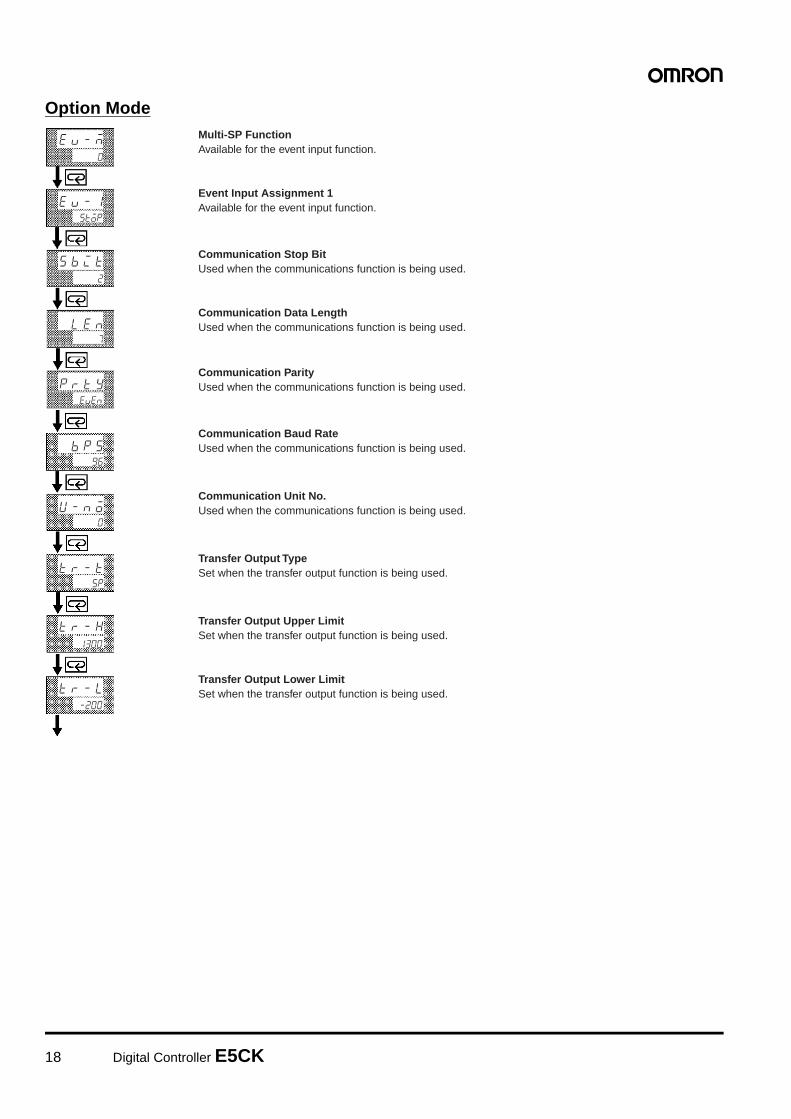
Multi-SP FunctionAvailable for the event input function.
Event Input Assignment 1Available for the event input function.
Communication Stop BitUsed when the communications function is being used.
Communication Data LengthUsed when the communications function is being used.
Communication ParityUsed when the communications function is being used.
Communication Baud RateUsed when the communications function is being used.
Communication Unit No.Used when the communications function is being used.
Transfer Output TypeSet when the transfer output function is being used.
Transfer Output Upper LimitSet when the transfer output function is being used.
Transfer Output Lower LimitSet when the transfer output function is being used.

Digital Controller E5CK 19
How to Use the Error DisplayWhen an error has occurred, the No.1 display alternately indicates error codes together with the current display item.This section describes how to check error codes on the display, and the actions that must be taken to remedy the problem.
Meaning Input is in error.
Action Check the wiring of inputs, disconnections, and shorts, and check the input type and the input type jumper con-nector.
Operation at Error For control output functions, output the manipulated variable matched to the setting of the “MV at PV error” param-eter (level 2 mode). Alarm output functions are activated when the upper limit is exceeded.
Meaning Internal memory operation is in error
Action First, turn the power OFF then back ON again. If the display remains the same, the E5CK Controller must be re-paired. If the display is restored to normal, the probable cause may be external noise affecting the control system.Check for external noise.
Operation at Error Control output functions turn OFF (2 mA max. at 4 to 20 mA output, and output equivalent to 0% in case of otheroutputs). Alarm output functions turn OFF.
Meaning Internal circuits are in error.
Action First, turn the power OFF then back ON again. If the display remains the same, the E5CK Controller must be re-paired. If the display is restored to normal, the probable cause may be external noise affecting the control system.Check for external noise.
Operation at Error Control output functions turn OFF (2 mA max. at 4 to 20 mA output, and output equivalent to 0% in case of otheroutputs). Alarm output functions turn OFF.
This error is output only during temperature input and is displayed for two seconds when the power is turned ON.
Meaning Calibration data is in error.
Action Must repair.
Operation at Error Both control output functions and alarm output functions are active. However, note that the readout accuracy is notassured.
Meaning Though not an error, this is displayed when the process value exceeds the display range when the control range(setting range ±10%) is larger than the display range (−1999 to 9999).
• When less than “−1999”
• When greater than “9999”Operation Control continues, allowing normal operation.
Input Error
Memory Error
A/D Converter Error
Calibration Data Error
Display Range Over

20 Digital Controller E5CK
Fuzzy Self-tuningFuzzy self-tuning is a function that enables the E5CK to calculate themost suitable PID constants for the controlled object.
Features• The E5CK determines by itself when to perform fuzzy self-tuning.
Fuzzy Self-tuning FunctionThe fuzzy self-tuning function has three modes.
In SRT (step response tuning) mode, the PID constants are tunedusing a step response method at the time the set point ischanged.In DT (disturbance tuning) mode, the PID constants are amendedso that the controlled temperature will be within the target rangeset in advance when there is external disturbance.In HT (hunting tuning) mode, when hunting occurs, the PID con-stants are amended to suppress the hunting.
Note: Be sure to turn on the power supply to the load either before orsimultaneously with the start of Temperature Controller opera-tion.Dead time will be measured from the time the TemperatureController starts operating. If a load such as a heater is turnedon after the Temperature Controller is turned on, dead timelonger than the actual value will be measured and inappropri-ate PID constants will be obtained. If an extremely largeamount of dead time is measured, the control amount will beset to 0% for a short period of time before being returned to100%, and the constants will then be retuned. Retuning is per-formed only for large amounts of dead time, so be sure to followthe precaution given above when starting operation.
Startup Conditions of SRTSRT will start if the following conditions are satisfied simultaneouslywhen the E5CK is turned on or the set point is changed.
Note: The last SRT-executed set point is set to 0 before shipping andwhen changing from advanced PID control to advanced PIDcontrol with fuzzy self-tuning.
PID Constant Refreshing ConditionsIf the step control amount is applied before the maximum tempera-ture slope (R) is obtained, SRT will not renew any PID constant. If theproportional band obtained from the R and L values that were mea-sured before the imposition had been completed is larger than thepresent proportional band, the PID constants will be renewedbecause the measured value is in the direction towards the suitableproportional band value, and the set point at that time will be theSRT-executed set point.
Stable Temperature StatusIf the temperature is within the stable range for a certain time, it isdeemed that the temperature is stable. This time is called stabilityjudgement time. Like PID constants, stability judgement time isadjusted with fuzzy self-tuning according to the characteristics of theobject to be controlled. Fuzzy self-tuning will not be activated if thetemperature is stable because the Temperature Controller deemsthat temperature control is smooth.
Balanced StatusIf the process value is within the stable range for 60 s when there isno output, it is deemed that the temperature is balanced.
Startup Conditions of DT1. DT will start if the temperature that has been stable varies due to
external disturbance and the deflection of the temperatureexceeds the stable range, and then the temperature becomesstable, provided that the number of maximum temperature valuesis less than four.
2. DT will start if the set point is changed under the condition thatSRT does not start and the temperature becomes stable, pro-vided that the number of maximum temperature values is lessthan four.If there are four or more maximum temperature values, HT willstart.
At the time the E5CK starts operating
At the time set point is changed
1. The set point at the time theE5CK starts operating is dif-ferent from the set point usedat the time SRT was last exe-cuted (see note).
2. The process value at the timethe E5CK starts operating issmaller than the set point inreverse operation and largerthan the set point in normaloperation.
1. The new set point is differentfrom the set point used at thetime SRT was last executed(see note).
2. The process value is in stablecondition before the set pointis changed.
3. A larger set point value is setin reverse operation and asmaller set point is set in nor-mal operation.
TemperatureSlope (R)
Stable range
Time
SP
Shorter than the stability judgement time
Stability judgement time
Stable Stable
Set point
Stable rangeStable range
(Set to 15.0°C before shipping)
SP
Temperature
Extreme value 2 Set point change
Time
Extreme value 1

Digital Controller E5CK 21
Startup Conditions of HTHT will be ON when there is hunting with four or more maximum tem-perature values (extreme values) while SRT is not being executed.
Note: In specific applications where temperature varies periodicallydue to disturbance, internal parameters need to be adjusted.For details, refer to the E5CK User’s Manual.
Extreme value 2 Extreme value 4
Temperature
Time
SP
Extreme value 1
Extreme value 3

22 Digital Controller E5CK
Precautions
Period and Scope of Guarantee
Unit with Standard Specifications
Scope of GuaranteeShould the Unit malfunction during the guarantee period, OMRONshall repair the Unit or replace any parts of the Unit at the expense ofOMRON.The above does not apply in the following cases.
1. Any malfunction of the Unit due to the incorrect use or improperhandling of the Unit.
2. Any malfunction of the Unit not originating from the Unit.3. Any malfunction of the Unit due to a modification of the Unit or
repairs to the Unit carried out by any person not authorized byOMRON.
4. Any malfunction of the Unit due to any natural disaster.
OMRON shall not be responsible for any damage or loss induced byany malfunction of the Unit.
Three-year Guarantee
Period of GuaranteeThe guarantee period of the Unit is three years starting from the datethe Unit is shipped from the factory.
Scope of GuaranteeThe Unit is guaranteed under the following operating conditions.
1. Average Operating Temperature (see note): −10°C to 50°C2. Mounting Method: Standard mounting
Note: Average Operating TemperatureRefer to the process temperature of the Unit mounted to a con-trol panel and connected to peripheral devices on condition thatthe Unit is in stable operation, sensor input type K is selectedfor the Unit, the positive and negative thermocouple input ter-minals of the Unit are short-circuited, and the ambient temper-ature is stable.
Should the Unit malfunction during the guarantee period, OMRONshall repair the Unit or replace any parts of the Unit at the expense ofOMRON.The above does not apply in the following cases.
1. Any malfunction of the Unit due to the incorrect use or improperhandling of the Unit.
2. Any malfunction of the Unit not originating from the Unit.3. Any malfunction of the Unit due to a modification of the Unit or
repairs to the Unit carried out by any person not authorized byOMRON.
4. Any malfunction of the Unit due to any natural disaster.
OMRON shall not be responsible for any damage or loss induced byany malfunction of the Unit.
Top
Bottom

Digital Controller E5CK 23
Warranty and Limitations of Liability
WARRANTYOMRON's exclusive warranty is that the products are free from defects in materials and workmanship for a period of one year (or other period ifspecified) from date of sale by OMRON.
OMRON MAKES NO WARRANTY OR REPRESENTATION, EXPRESS OR IMPLIED, REGARDING NON-INFRINGEMENT, MERCHANTABILITY,OR FITNESS FOR PARTICULAR PURPOSE OF THE PRODUCTS. ANY BUYER OR USER ACKNOWLEDGES THAT THE BUYER OR USERALONE HAS DETERMINED THAT THE PRODUCTS WILL SUITABLY MEET THE REQUIREMENTS OF THEIR INTENDED USE. OMRON DIS-CLAIMS ALL OTHER WARRANTIES, EXPRESS OR IMPLIED.
LIMITATIONS OF LIABILITYOMRON SHALL NOT BE RESPONSIBLE FOR SPECIAL, INDIRECT, OR CONSEQUENTIAL DAMAGES, LOSS OF PROFITS, OR COMMER-CIAL LOSS IN ANY WAY CONNECTED WITH THE PRODUCTS, WHETHER SUCH CLAIM IS BASED ON CONTRACT, WARRANTY, NEGLI-GENCE, OR STRICT LIABILITY.
In no event shall the responsibility of OMRON for any act exceed the individual price of the product on which liability is asserted.
IN NO EVENT SHALL OMRON BE RESPONSIBLE FOR WARRANTY, REPAIR, OR OTHER CLAIMS REGARDING THE PRODUCTS UNLESSOMRON'S ANALYSIS CONFIRMS THAT THE PRODUCTS WERE PROPERLY HANDLED, STORED, INSTALLED, AND MAINTAINED AND NOTSUBJECT TO CONTAMINATION, ABUSE, MISUSE, OR INAPPROPRIATE MODIFICATION OR REPAIR.
Application Considerations
SUITABILITY FOR USEOMRON shall not be responsible for conformity with any standards, codes, or regulations that apply to the combination of products in the custom-er's application or use of the products.
At the customer's request, OMRON will provide applicable third party certification documents identifying ratings and limitations of use that applyto the products. This information by itself is not sufficient for a complete determination of the suitability of the products in combination with the endproduct, machine, system, or other application or use.
The following are some examples of applications for which particular attention must be given. This is not intended to be an exhaustive list of allpossible uses of the products, nor is it intended to imply that the uses listed may be suitable for the products.
• Outdoor use, uses involving potential chemical contamination or electrical interference, or conditions or uses not described in this catalog.• Nuclear energy control systems, combustion systems, railroad systems, aviation systems, medical equipment, amusement machines, vehicles,
safety equipment, and installations subject to separate industry or government regulations.• Systems, machines, and equipment that could present a risk to life or property. Please know and observe all prohibitions of use applicable to the products.
NEVER USE THE PRODUCTS FOR AN APPLICATION INVOLVING SERIOUS RISK TO LIFE OR PROPERTY WITHOUT ENSURING THAT THESYSTEM AS A WHOLE HAS BEEN DESIGNED TO ADDRESS THE RISKS, AND THAT THE OMRON PRODUCTS ARE PROPERLY RATEDAND INSTALLED FOR THE INTENDED USE WITHIN THE OVERALL EQUIPMENT OR SYSTEM.

24
In the interest of product improvement, specifications are subject to change without notice.
ALL DIMENSIONS SHOWN ARE IN MILLIMETERS.
To convert millimeters into inches, multiply by 0.03937. To convert grams into ounces, multiply by 0.03527.
Cat. No. H079-E1-06
OMRON CorporationIndustrial Automation Company
Measuring and Control DivisionShiokoji Horikawa, Shimogyo-ku,Kyoto, 600-8530 JapanTel: (81)75-344-7080/Fax: (81)75-344-7189
Printed in Japan0303-0.5M (0995) (A)


