Dynamics of Rolling Tyre Tread Blocks with Frictional ... · Conclusion •Modular model considers...
27
Titel February 10, 2009, Cologne Tiretech 2010 8 Dynamics of Rolling Tyre Tread Blocks with Frictional Contact and Wear Patrick Moldenhauer Matthias Kröger Institut of Machine Elements, Design and Manufacturing Technical University Freiberg Germany • Introduction • Tread block modelling • Simulation results • Conclusion
Transcript of Dynamics of Rolling Tyre Tread Blocks with Frictional ... · Conclusion •Modular model considers...
Titel
February 10, 2009, Cologne
Tiretech 2010 8
Dynamics of Rolling Tyre Tread Blocks
with Frictional Contact and Wear
Patrick Moldenhauer
Matthias KrögerInstitut of Machine Elements, Design and Manufacturing
Technical University Freiberg
Germany
• Introduction
• Tread block modelling
• Simulation results
• Conclusion
February 10, 2009, Cologne
Tiretech 2010 9
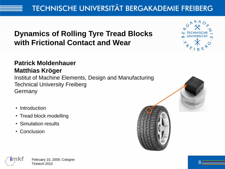
Examples of modeled systems with elastomers
Windscreen
wiper
Window seals
Tyre tread blocks
Focus on
friction induced vibrations
seals e.g. in
brake systems
Judder:
comfort problemSqueal:
function problem
Squeal:
comfort problem
Judder: function and
comfort problem
February 10, 2009, Cologne
Tiretech 2010 10
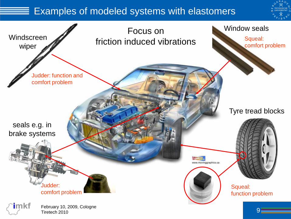
• Highly sophisticated 3D models
• Non-linear material description
• Thermo-mechanical coupling
• Numerically very expensive
[Hofstetter 2004]
[Gleu 2001]
[Larsson & Barrelet 2002]
Introduction
• Simple models (1 to 3 DOF)
• Neglect of geometry and structural effects
• Fast calculation
• Mostly add-ons for tyre models
Steady state simulations Dynamic simulations
Stress distribution
Temperature distribution
1D contact element
2 DOF oscillator
February 10, 2009, Cologne
Tiretech 2010 11
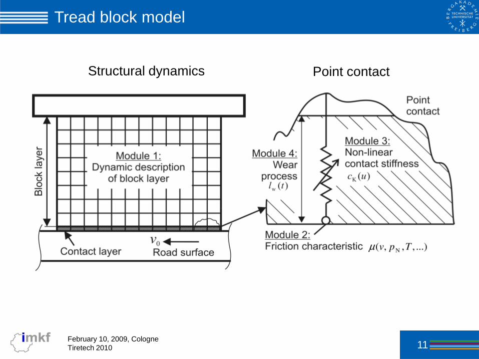
Tread block model
Point contactStructural dynamics
February 10, 2009, Cologne
Tiretech 2010 12
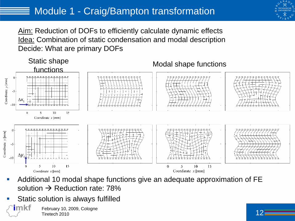
Module 1 - Craig/Bampton transformation
Additional 10 modal shape functions give an adequate approximation of FE
solution Reduction rate: 78%
Static solution is always fulfilled
1x
1y
Aim: Reduction of DOFs to efficiently calculate dynamic effects
Idea: Combination of static condensation and modal description
Decide: What are primary DOFs
Static shape
functionsModal shape functions
February 10, 2009, Cologne
Tiretech 2010 13
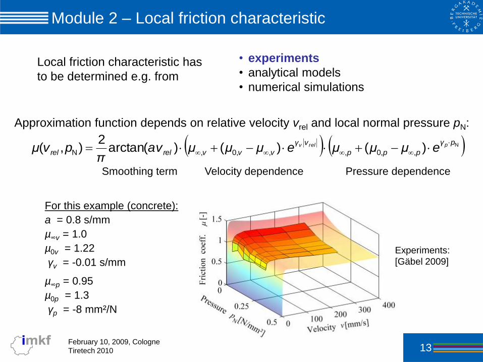
Local friction characteristic has
to be determined e.g. from
Module 2 – Local friction characteristic
For this example (concrete):
a = 0.8 s/mm
µ∞v = 1.0
µ0v = 1.22
γv = -0.01 s/mm
µ∞p = 0.95
µ0p = 1.3
γp = -8 mm²/N
N)()()(arctan2
),( ,,0,,,0,N
pγ
ppp
vγ
vvvrelrelprelv eμμμeμμμva
πpvμ
• experiments
• analytical models
• numerical simulations
Approximation function depends on relative velocity vrel and local normal pressure pN:
Smoothing term Velocity dependence Pressure dependence
Experiments:
[Gäbel 2009]

February 10, 2009, Cologne
Tiretech 2010 14
N
NN
Δ
Δ
s
Fc
Few junctions:
large increase of local pressure high deformations small contact stiffness
Many junctions
relatively smaller increase of local pressure small deformations high stiffness
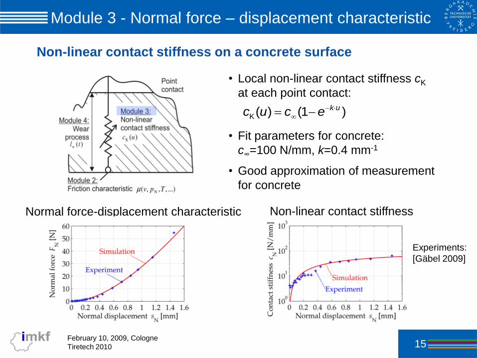
Module 3 - Normal force – displacement characteristic
FN=120 N
FN=60 N
FN=90 N
FN=30 N
Investigation of non-linear force-displacement characteristic
Global contact stiffness
[Gäbel 2009]
February 10, 2009, Cologne
Tiretech 2010 15
• Local non-linear contact stiffness cK
at each point contact:
• Fit parameters for concrete:
c∞=100 N/mm, k=0.4 mm-1
• Good approximation of measurement
for concrete
)1()(K
ukecuc
Normal force-displacement characteristic Non-linear contact stiffness
Module 3 - Normal force – displacement characteristic
Experiments:
[Gäbel 2009]
Non-linear contact stiffness on a concrete surface
February 10, 2009, Cologne
Tiretech 2010 16
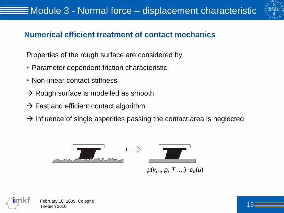
Module 3 - Normal force – displacement characteristic
µ(vrel, p, T, ...), cK(u)
Properties of the rough surface are considered by
• Parameter dependent friction characteristic
• Non-linear contact stiffness
Rough surface is modelled as smooth
Fast and efficient contact algorithm
Influence of single asperities passing the contact area is neglected
Numerical efficient treatment of contact mechanics
February 10, 2009, Cologne
Tiretech 2010 17
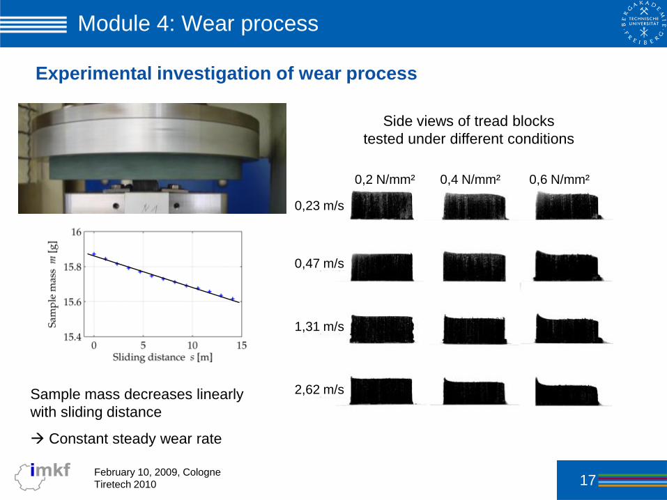
Module 4: Wear process
Experimental investigation of wear process
Side views of tread blocks
tested under different conditions
0,23 m/s
0,47 m/s
1,31 m/s
2,62 m/s
0,2 N/mm² 0,4 N/mm² 0,6 N/mm²
Sample mass decreases linearly
with sliding distance
Constant steady wear rate
February 10, 2009, Cologne
Tiretech 2010 18
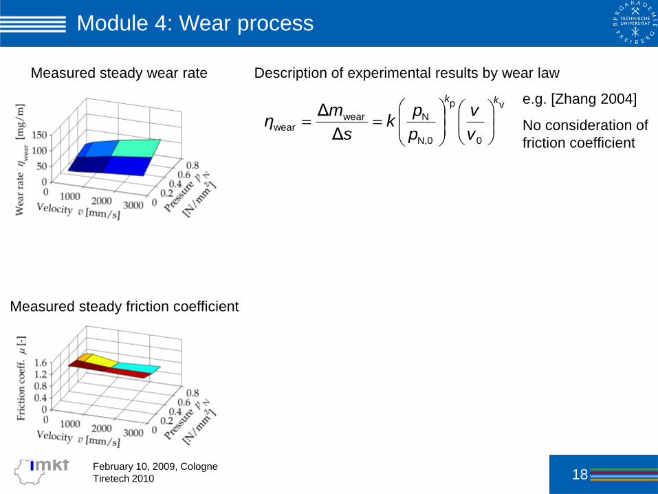
Measured steady wear rate
Measured steady friction coefficient
Module 4: Wear process
v
0
p
N,0
Nwearwear
Δ
Δkk
v
v
p
pk
s
mη
Description of experimental results by wear law
e.g. [Zhang 2004]
No consideration of
friction coefficient
February 10, 2009, Cologne
Tiretech 2010 19
h
v
0
p
N,0
N
N
0Nwear),(
1),(*
kk
v
v
p
p
pvμkpvη
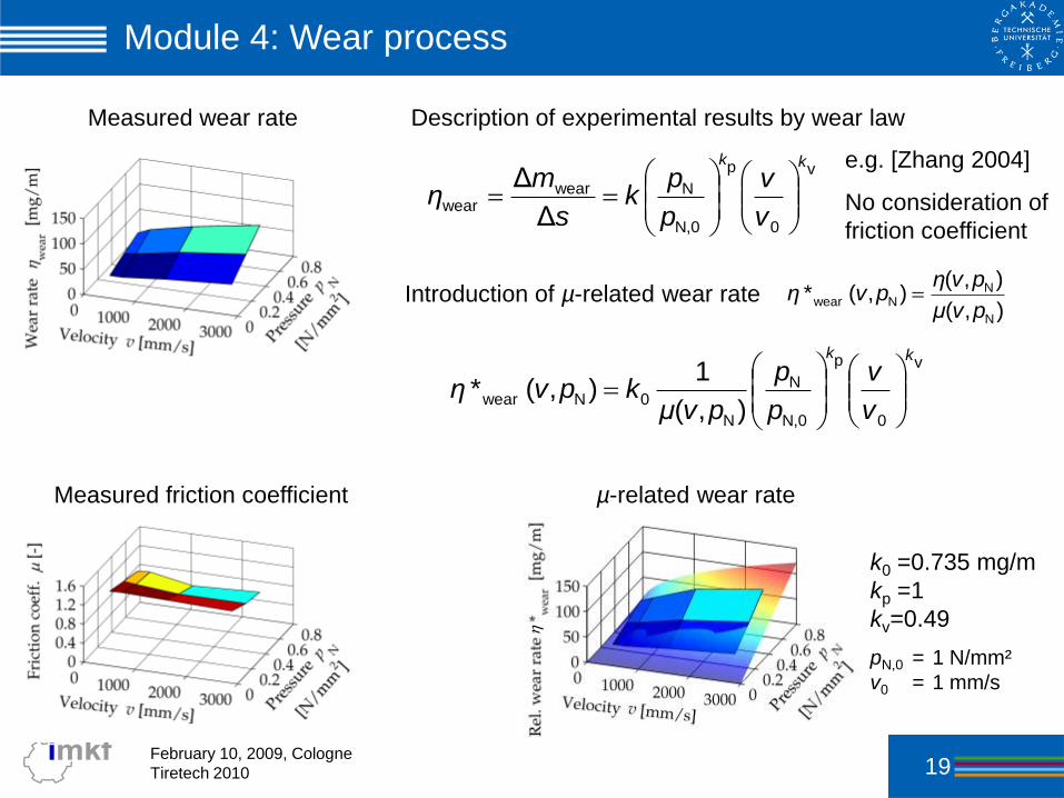
k0 =0.735 mg/m
kp =1
kv=0.49
pN,0 = 1 N/mm²
v0 = 1 mm/s
Measured wear rate
Measured friction coefficient
v
0
p
N,0
Nwearwear
Δ
Δkk
v
v
p
pk
s
mη
Description of experimental results by wear law
e.g. [Zhang 2004]
No consideration of
friction coefficient
Introduction of µ-related wear rate),(
),(),(*
N
NNwear
pvμ
pvηpvη
µ-related wear rate
Module 4: Wear process
February 10, 2009, Cologne
Tiretech 2010 20
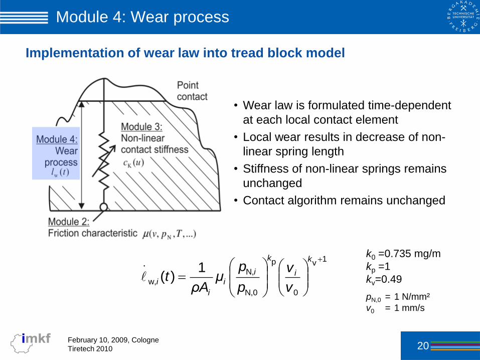
Module 4: Wear process
• Wear law is formulated time-dependent
at each local contact element
• Local wear results in decrease of non-
linear spring length
• Stiffness of non-linear springs remains
unchanged
• Contact algorithm remains unchanged
1v
0
p
N,0
N,
w,
1)(
k
i
k
i
i
i
iv
v
p
pμ
Aρt
.
Implementation of wear law into tread block model
k0 =0.735 mg/m
kp =1
kv=0.49
pN,0 = 1 N/mm²
v0 = 1 mm/s
February 10, 2009, Cologne
Tiretech 2010 21
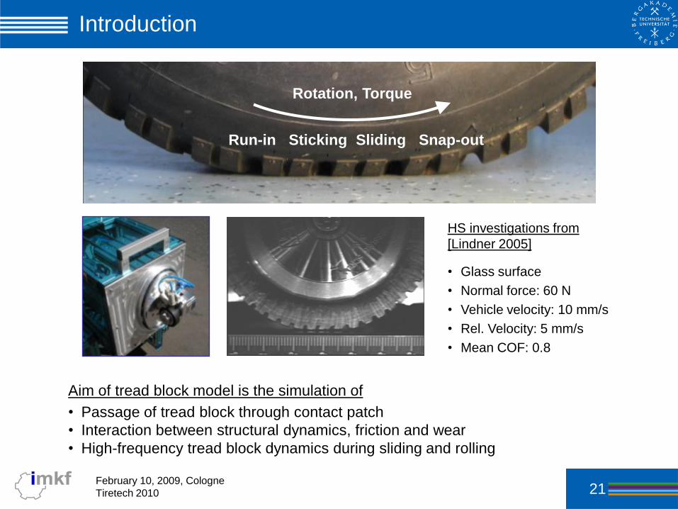
Introduction
Run-in Sticking Sliding Snap-out
Rotation, Torque
Aim of tread block model is the simulation of
• Passage of tread block through contact patch
• Interaction between structural dynamics, friction and wear
• High-frequency tread block dynamics during sliding and rolling
• Glass surface
• Normal force: 60 N
• Vehicle velocity: 10 mm/s
• Rel. Velocity: 5 mm/s
• Mean COF: 0.8
HS investigations from
[Lindner 2005]
February 10, 2009, Cologne
Tiretech 2010 22
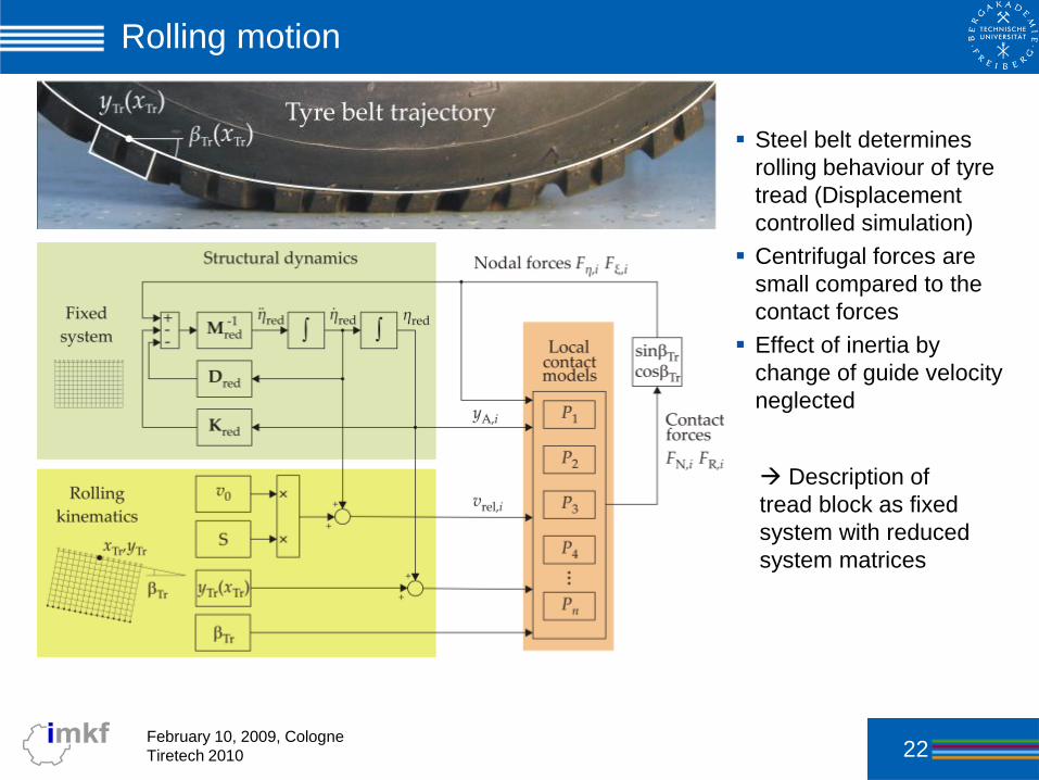
Rolling motion
Steel belt determines
rolling behaviour of tyre
tread (Displacement
controlled simulation)
Centrifugal forces are
small compared to the
contact forces
Effect of inertia by
change of guide velocity
neglected
Description of
tread block as fixed
system with reduced
system matrices

February 10, 2009, Cologne
Tiretech 2010 23
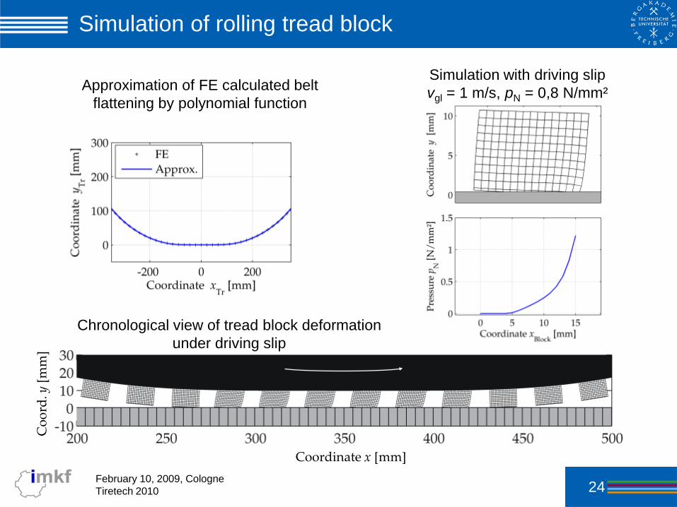
Simulation of rolling tread block
Approximation of FE calculated belt
flattening by polynomial function
Coordinate x [mm]
Chronological view of tread block deformation
under driving slip
Co
ord
. y[m
m]
Simulation with driving slip
vgl = 1 m/s, pN = 0,8 N/mm²
February 10, 2009, Cologne
Tiretech 2010 24
Simulation of rolling tread block
Approximation of FE calculated belt
flattening by polynomial function
Coordinate x [mm]
Chronological view of tread block deformation
under driving slip
Co
ord
. y[m
m]
Simulation with driving slip
vgl = 1 m/s, pN = 0,8 N/mm²

February 10, 2009, Cologne
Tiretech 2010 25
Simulation of rolling tread block
• Allocation of sticking, sliding and snap-out phase
• Sticking zone decreases with increasing slip
• No sticking occurs for high slip
Deformation behaviour of leading edge under variation of tyre braking slip
Normal pressure pN = 1,0 N/mm², Vehicle velocity vC = 20 m/s
C
C
v
rωvS
Slip definition
February 10, 2009, Cologne
Tiretech 2010 26
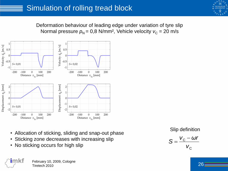
Simulation of rolling tread block
• Allocation of sticking, sliding and snap-out phase
• Sticking zone decreases with increasing slip
• No sticking occurs for high slip
Deformation behaviour of leading edge under variation of tyre slip
Normal pressure pN = 0,8 N/mm², Vehicle velocity vC = 20 m/s
C
C
v
rωvS
Slip definition
February 10, 2009, Cologne
Tiretech 2010 27
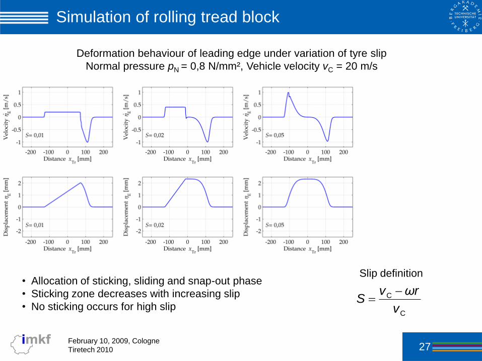
Simulation of rolling tread block
• Allocation of sticking, sliding and snap-out phase
• Sticking zone decreases with increasing slip
• No sticking occurs for high slip
Deformation behaviour of leading edge under variation of tyre slip
Normal pressure pN = 0,8 N/mm², Vehicle velocity vC = 20 m/s
C
C
v
rωvS
Slip definition
February 10, 2009, Cologne
Tiretech 2010 28
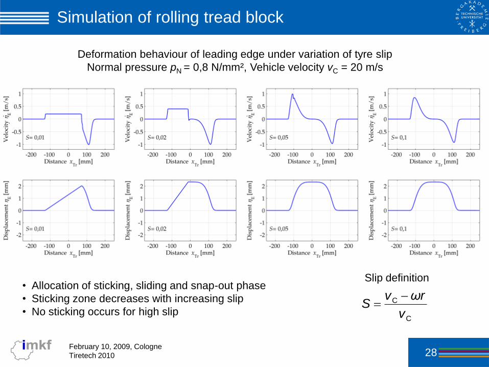
Simulation of rolling tread block
• Allocation of sticking, sliding and snap-out phase
• Sticking zone decreases with increasing slip
• No sticking occurs for high slip
Deformation behaviour of leading edge under variation of tyre slip
Normal pressure pN = 0,8 N/mm², Vehicle velocity vC = 20 m/s
C
C
v
rωvS
Slip definition
February 10, 2009, Cologne
Tiretech 2010 29
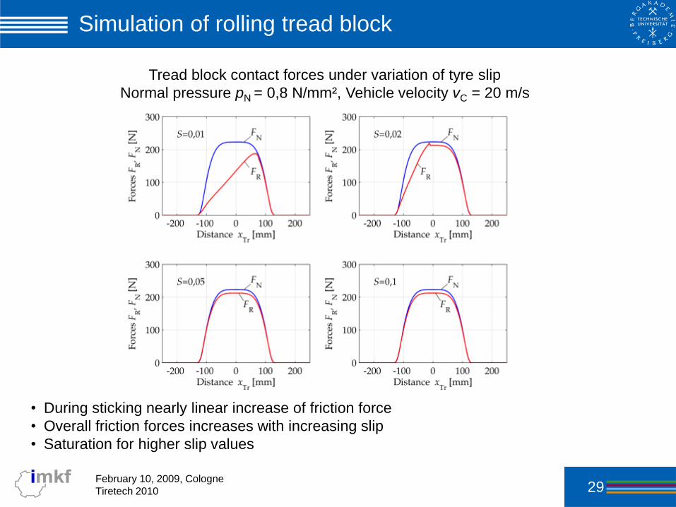
Simulation of rolling tread block
• During sticking nearly linear increase of friction force
• Overall friction forces increases with increasing slip
• Saturation for higher slip values
Tread block contact forces under variation of tyre slip
Normal pressure pN = 0,8 N/mm², Vehicle velocity vC = 20 m/s
February 10, 2009, Cologne
Tiretech 2010 30
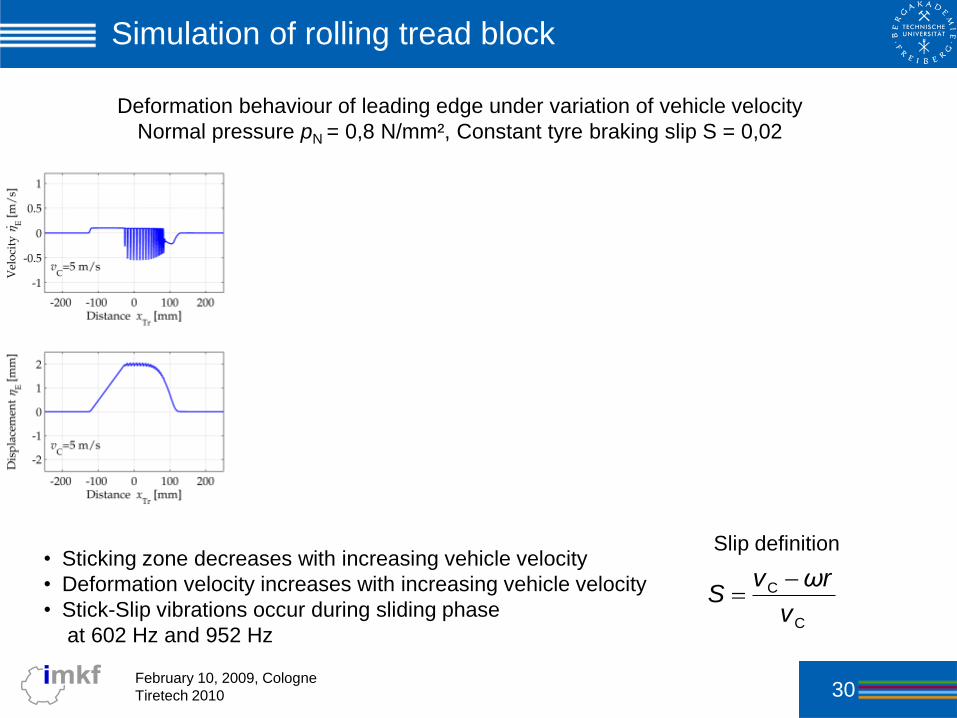
Simulation of rolling tread block
• Sticking zone decreases with increasing vehicle velocity
• Deformation velocity increases with increasing vehicle velocity
• Stick-Slip vibrations occur during sliding phase
at 602 Hz and 952 Hz
Deformation behaviour of leading edge under variation of vehicle velocity
Normal pressure pN = 0,8 N/mm², Constant tyre braking slip S = 0,02
C
C
v
rωvS
Slip definition
February 10, 2009, Cologne
Tiretech 2010 31
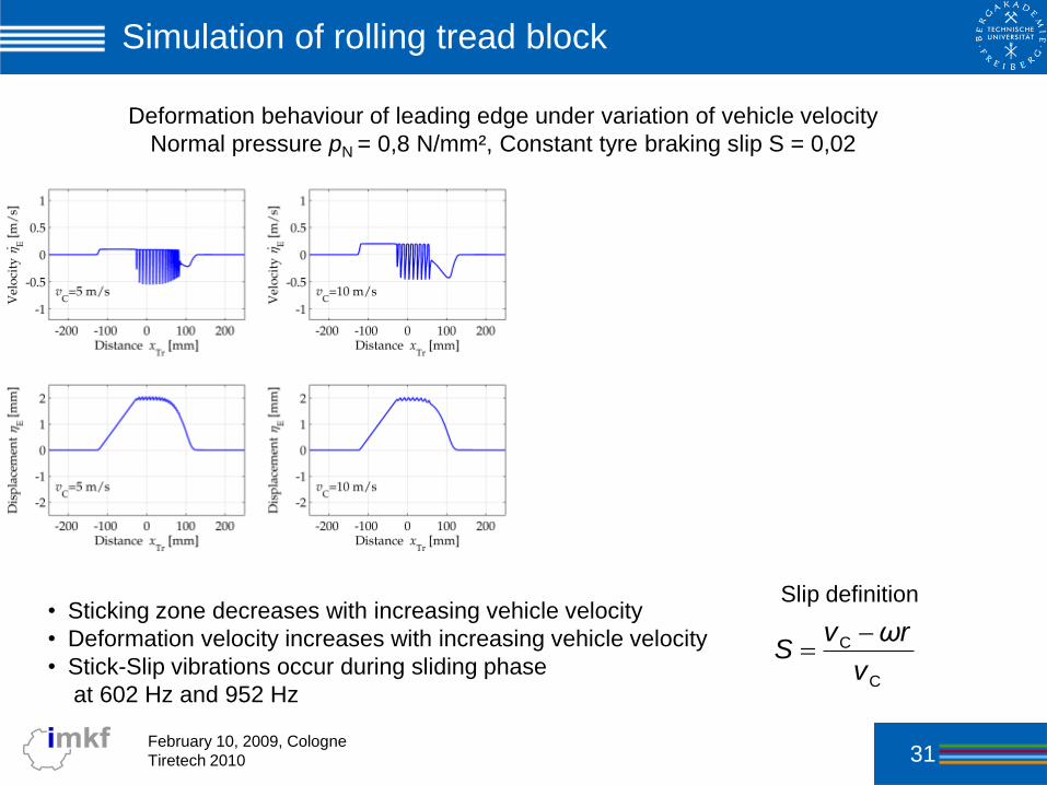
Simulation of rolling tread block
• Sticking zone decreases with increasing vehicle velocity
• Deformation velocity increases with increasing vehicle velocity
• Stick-Slip vibrations occur during sliding phase
at 602 Hz and 952 Hz
Deformation behaviour of leading edge under variation of vehicle velocity
Normal pressure pN = 0,8 N/mm², Constant tyre braking slip S = 0,02
C
C
v
rωvS
Slip definition
February 10, 2009, Cologne
Tiretech 2010 32
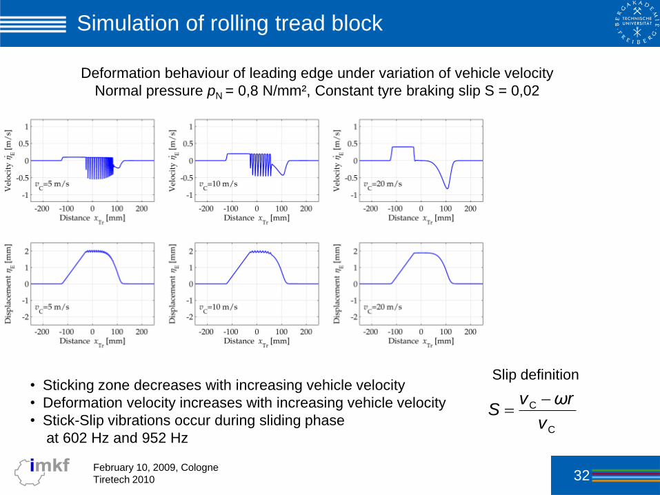
Simulation of rolling tread block
• Sticking zone decreases with increasing vehicle velocity
• Deformation velocity increases with increasing vehicle velocity
• Stick-Slip vibrations occur during sliding phase
at 602 Hz and 952 Hz
Deformation behaviour of leading edge under variation of vehicle velocity
Normal pressure pN = 0,8 N/mm², Constant tyre braking slip S = 0,02
C
C
v
rωvS
Slip definition
February 10, 2009, Cologne
Tiretech 2010 33
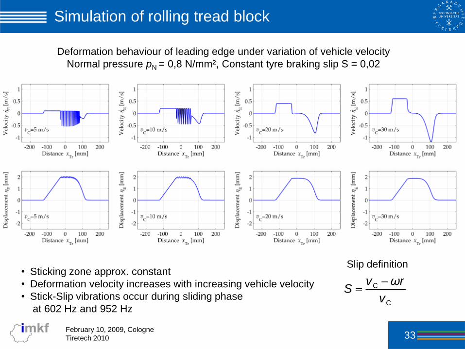
Simulation of rolling tread block
• Sticking zone approx. constant
• Deformation velocity increases with increasing vehicle velocity
• Stick-Slip vibrations occur during sliding phase
at 602 Hz and 952 Hz
Deformation behaviour of leading edge under variation of vehicle velocity
Normal pressure pN = 0,8 N/mm², Constant tyre braking slip S = 0,02
C
C
v
rωvS
Slip definition
February 10, 2009, Cologne
Tiretech 2010 34
Conclusion
• Modular model considers structural dynamics, parameter
dependent friction, non-linear contact stiffness and wear
• Craig/Bampton transformation allows efficient calculation of the
tread block dynamics
• Rough surface is modelled as smooth with respective non-linear
contact stiffness and local friction characteristic
• Experimentally identified non-linear friction characteristic and wear
law are implemented
• Implementation of global tyre kinematics allows deeper insight into
processes in the tyre contact patch including stick-slip phenomena
Thanks to Deutsche Forschungsgemeinschaft (DFG FOR492)
Forschergruppe “Dynamical contact problems with friction of elastomers”