DYNAMIC POSITIONING CONFERENCE October 9...
13
DYNAMIC POSITIONING CONFERENCE October 9-10, 2012 POWER SESSION Improved and Efficient Power and Thruster System for DP Drilling Vessels with New Generation Protection System and Azipod ® CZ By Jan Fredrik Hansen, Frank Wendt, Teemu Jehkonen, Jukka Varis, Lauri Tiainen ABB
Transcript of DYNAMIC POSITIONING CONFERENCE October 9...

Author’s Name Name of the Paper Session
DYNAMIC POSITIONING CONFERENCE October 9-10, 2012
POWER SESSION
Improved and Efficient Power and Thruster System
for DP Drilling Vessels with New Generation
Protection System and Azipod®
CZ
By Jan Fredrik Hansen, Frank Wendt,
Teemu Jehkonen, Jukka Varis, Lauri Tiainen
ABB
owner
Text Box
Return to session menu

Hansen et.al, ABB Improved and Efficient Power and Thruster System...
MTS Dynamic Positioning Conference October 9-10, 2012 Page 2
ABSTRACT
IEC 61850 Communication standard is introduced for marine medium voltage switchboards.
This communication standard enables the possibility for the protection relays and controllers
related to power management and variable speed drive control to have a direct bus
communication.
Using this system in DP drilling vessels has a range of advantages for the installation and
operation:
- Reduced internal and external wiring in and to/from the main 11kV SWBD, hence
increasing the reliability.
- Enables possibility for fast zone protection (less than 70ms), which can replace
traditional busbar differential protection system with its HW components.
- Enables fast communication to Power Management System and Diesel Generator
Monitoring Systems. Actions in case of failures can be done faster to prevent
unintentional tripping of generators.
- Enables fast communication to drilling and thruster drive systems for fast and
accurate load reduction in case of generator and engine failures.
- Simplifies the transfer of statuses, measurements, and logs to supervisory systems to
support fault diagnostics and maintenance.
Azipod®CZ is an electric podded thruster with a low voltage permanent magnet electric
motor, nozzle, and the whole unit can be tilted to optimize the bollard pull. The unit is
available up to 4.7MW and well suited for DP drilling vessels.
The Azipod®CZ design is targeted to maximize the efficiency within the optimization
constraints, as well as reducing complexity and simplify installation and maintenance.
Considering efficiency of all components and aspects from electric motor and auxiliaries to
the hydrodynamic effect of tilting, an annual energy saving of 15% compared to mechanical
thrusters can be anticipated given a typical operation profile.
In combination with the new IEC 61850 communication scheme enables an efficient and
reliable power and thruster plant for DP Drilling vessels.

Hansen et.al, ABB Improved and Efficient Power and Thruster System...
MTS Dynamic Positioning Conference October 9-10, 2012 Page 3
1. Introduction
Electric power and thruster systems for DP operated drilling vessels have gradually improved
and become more efficient and reliable during the past decades. New products, HW and
functionality has become available over the years, and the systems as delivered today are
designed for minimizing the risk of blackouts and reducing the start-up time after blackouts.
However there is still room for improvements both for the total reliability and also efficiency,
which is becoming increasingly more important. In this article we will present the benefits
and improvements by the introduction of new protection relay series with fast bus
communication on the IEC 61850 standard, and the utilization of the energy efficient Azipod®
CZ thrusters.
The new generation of protection relays with the possibility to communicate on the IEC
61850 standard opens up new possibilities for optimizing the power plant design and
increasing the level of safety [1]. First of all the bus communication between each relay and
to/from IAS/PMS simplifies the construction of the switchboard and nearly removes the need
for auxiliary and signal wirings internally and externally. Further integration with PLCs also
communicating on the same standard, makes it easier to include additional supervisory
protection functions as Diesel Generator Monitoring System (DGMS), and Power
Management Systems (PMS) both physically and functionally into the main SWBDs.
Further, the communication and integration can easily be extended to include also power
consumers using variable speed drive controllers, such as thruster and drilling drives. This
opens for new opportunities to improve the functional integration of load control and blackout
prevention, and the fast communication between the power producing elements and the
consumers gives benefits for fast load reduction and reduced risks for blackouts or partial
blackouts.
Azipod®CZ is an electric podded thruster that is specially developed for optimized bollard
pull for drilling vessels [2]. By the combination of the use of direct motor connection,
permanent magnet motor technology, tilting of the complete thruster unit, and a minimum of
auxiliary components, up to 15% yearly energy savings can be achieved compared to
mechanical L-Drive thrusters for a given operation profile. With the current solution,
Azipod®CZ provides a simple interface for the customer as only the steering and propulsion
drives are the main components to be integrated to the ship power system.
In this article we will first describe the characteristics of the new protection relays and the
power system configuration, and then continue with discussing the benefits this system
enables for a better performance and reduced risks for blackout. Then the main benefits of
Azipod®CZ is discussed, and with special attention to energy saving and simplicity of
installation.
2. New Generation Protection Relays and IEC 61850
The introduction of the IEC 61850 standard represents a technology milestone in power plant
automation by simplifying the integration of protection relays and power plant as well as
process automation. The standard defines the communication system, data models and
abstract services to access data which ensures the interoperability between devices. In IEC
61850-based architectures, conventional wiring has been eliminated and these signals are
transmitted and received via the communications interface. Thus, the communication
interface in the new IEC 61850-based IEDs (Intelligent Electronic Devise) must be very
efficient at processing the communication data. Two communication methods for data
exchange are applied:

Hansen et.al, ABB Improved and Efficient Power and Thruster System...
MTS Dynamic Positioning Conference October 9-10, 2012 Page 4
MMS –Client / Server Communication specifies a method of exchanging non-time-
critical data through local-area networks. The use of MMS allows provisions for
supporting both centralized and distributed architectures. This standard includes the
exchange of real-time data, indications, control operations and report notification.
GOOSE –Publish / Subscribe Communication. GOOSE (Generic Object Oriented
System Event) is used to model the transmission of high priority information like trip
commands or interlocking information. The model is based on cyclic and high-
priority transmission of status information.
IEC 61850 uses Ethernet as the basic communication technology. In order to ensure high
performance and reliability in the communication a switched Ethernet network architecture is
used. Benefits of a switched Ethernet network architecture include:
Real-time network performance to develop deterministic systems.
Security &Reliability.
Manageability and ease-of-use features.
Flexible communication topologies.
Use of standard Ethernet protocols,
e.g. SNTP for time synchronization, SNMP for network supervision, QoS to priories
transfer of time critical data.
2.1 ABB’s Relion® protection and control product family
ABB’s Relion® protection and control product family was one of the first to undergo the IEC
61850 transformation and was designed from the beginning for a native implementation of
IEC 61850. The new platform architecture integrates communication services and data
representation into the core protection and control applications. Protection and control
algorithms, which provides the protection relay core functionality, are modelled and
implemented fully according to IEC 61850 standard rules. Thereby the data models are
supported directly in the protection and control functions and the data is directly accessible
from the communication services. No time consuming additional data mapping and
conversion processes are required, making the data in the protection relay directly available
which is a key factor in communication performance.
2.2 IEC 61850 Communication, GOOSE
As communication method in a medium voltage switchboard between protection relays as
well as high priority information to the automation system, GOOSE is used. GOOSE
messages are user defined data. When a change in a contained data item is detected, the data
is send immediately at a high priority. The data is sent multiple times to ensure reception of
the data, Figure 1.
Figure 1 GOOSE communication time line [1]
GOOSE provides the fast peer-to-peer information exchange between the output data values
of one IED to the input data of many other IEDs (multicast) based on publisher and subscriber
mechanism. In principle all measurement and status values can be shared between IEDs and
IEC 61850 supporting control systems. GOOSE communication replaces hardwired signals
within the switchboard and towards the automation system and makes more information
available without need for additional hardware.

Hansen et.al, ABB Improved and Efficient Power and Thruster System...
MTS Dynamic Positioning Conference October 9-10, 2012 Page 5
GOOSE
Control/Monitoring
SwBd bus IEC61850
IED IED IED
IED
Automation
Figure 2 Typical communication topology [1]
Following the IEC 61850 standard means that peer-to-peer signalling is faster than traditional
hard-wired loops. ABB’s new Relion® 615 and 630 series products achieve the performance
class T1AP1 with transmission time <10ms in all operating conditions. With communication
performance and increased amount of signals available between protection relays makes more
advanced protection schemes are feasible.
Further benefits of GOOSE communication are:
Automatically supervised connections
Connection failures are always detected
Data quality sent to peer IEDs along with event to enable data validation
Preconfigured fail-safe value in case of failure
Indication of communication loss
More I/O without hardware changes or additions
Expandability
IED retrofit installations with just small wiring changes
New functionality can be introduced
Flexibility
Possibility to easily add functionality afterwards
IEDs can share unused I/O
2.3 Utilizing IEC 61850 in Marine Switchboard Design
Utilizing IEC 61850 in a marine switchboard introduces a common switchboard
communication network. The switchboard network is designed as private and isolated local
area network (LAN). On the physical layer the Ethernet network operates with a speed of 100
Mbps in full-duplex. A switched Ethernet configuration is used where all devises are cross
connected through switches. The arrangement of Ethernet switches and the connection
between them defines the network topology. A switched Ethernet provides a fast and reliable
transmission by giving each device full bandwidth in both transmission directions and
forming a collision free domain. This configuration is crucial to fulfil the requirements for
time critical signal transfer in IEC61850. Redundancy is managed within the communication
network by connecting the Ethernet switches in a multiple ring topology. Every Ethernet
switch has two inter-switch links and thus any two end nodes (IED, controller, PC, etc) which
are not connected to the same Ethernet switch have two paths between them when all
components are in operation.

Hansen et.al, ABB Improved and Efficient Power and Thruster System...
MTS Dynamic Positioning Conference October 9-10, 2012 Page 6
All signal transfer between protection relays, signal interface to the automation and
monitoring system as well as data communication for diagnostic and service purpose will use
this common communication infrastructure. With fast peer-to-peer communication available
between protection relays new switchboard protection schemes are feasible. Figure 3 shows
an example set-up of IEC 61850 configuration in a marine power system.
G G
11kV HV SwBd
11kV HV
SwBd xx
11kV HV
SwBd xx
RE 615
RE 615 RE 615
RE 615
RE 615
RE 630
RE 630
RE 615
(Sla
ve
)
RE 615
RE 630
RE 630 RE 630
(Ma
ste
r)
RE 615
RE 615 RE 615
RE 615A
C8
00
M
AC
80
0M
Pre
-Ma
g
48
0V
Dis
tr.
48
0V
Drill.
Dis
tr.
Drill.
Drive
VS
D
48
0V
Drill
Dis
tr.
RE 615
48
0V
Dis
tr.
Pre
-Ma
gDrilling VSD
Control
AC800MAC800M
Automomous
Thruster Control
AC800M AC800M
Th
ruste
r
VS
D
Drill.
Drive
VS
D
Th
ruste
r
VS
D
IEC61850 100Mbit/s Ethernet
DGMS Controller
Monitoring/Control
Vessel Automation
System
Maintenance Station
IED tool
PCM600
WEB HMI
Drilling VSD
Control
Automomous
Thruster Control Figure 3 Typical configuration for a drilling vessel (one of multiple SWBD sections)
Advantages:
One communication network with one communication standard only
Ring communication topology providing network redundancy
No hardwired signals
Every signal between protection relays and to PLC controller is loop monitored
Fast peer-to-peer communication between relays and to PLC controller
More information available
New switchboard protection schemes
Accurate time synchronization
Following two examples illustrates the possibilities:
Example 1:
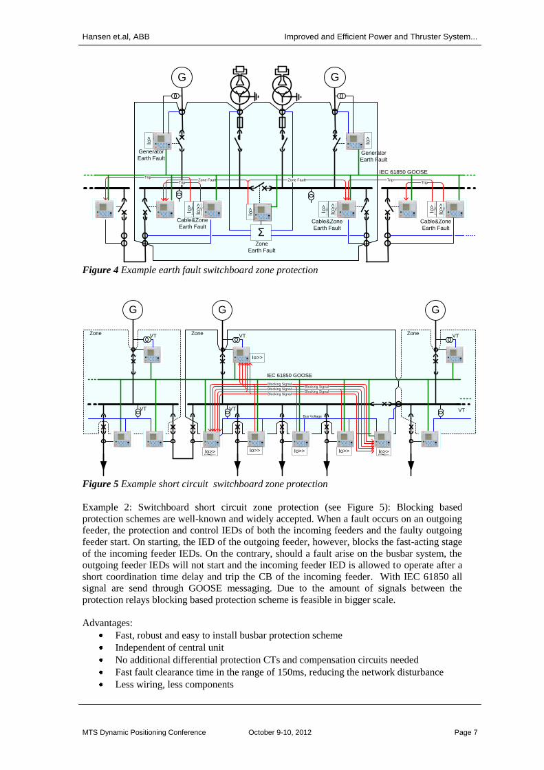
Switchboard earth fault zone protection (see Figure 4): Switchboard requires multiple signal
connection between protection relays within and between switchboard sections. With IEC
61850 all signal are send through GOOSE messaging. In difference to traditional hardwired
solution the signal are loop monitored which reduces the risk for hidden system and
component failures.
Hansen et.al, ABB Improved and Efficient Power and Thruster System...
MTS Dynamic Positioning Conference October 9-10, 2012 Page 7
G G
Σ
IEC 61850 GOOSE
Trip
Io>
Io>
>
Io>
Zone Fault Zone Fault
Io>
Trip
Io>
>
Io>
TripTrip
Io>
>
Io>
Io>
Cable&Zone
Earth Fault
Zone
Earth Fault
Cable&Zone
Earth Fault
Cable&Zone
Earth Fault
Generator
Earth Fault Generator
Earth Fault
Figure 4 Example earth fault switchboard zone protection
VT
G
IEC 61850 GOOSE
Zone
Bus Voltage
VT
G
VT
VT
G
VT
VT
Zone Zone
Blocking SignalBlocking Signal
Blocking Signal
Blocking SignalBlocking Signal
Io>> Io>> Io>>
Io>>
Io>> Io>>
Figure 5 Example short circuit switchboard zone protection
Example 2: Switchboard short circuit zone protection (see Figure 5): Blocking based
protection schemes are well-known and widely accepted. When a fault occurs on an outgoing
feeder, the protection and control IEDs of both the incoming feeders and the faulty outgoing
feeder start. On starting, the IED of the outgoing feeder, however, blocks the fast-acting stage
of the incoming feeder IEDs. On the contrary, should a fault arise on the busbar system, the
outgoing feeder IEDs will not start and the incoming feeder IED is allowed to operate after a
short coordination time delay and trip the CB of the incoming feeder. With IEC 61850 all
signal are send through GOOSE messaging. Due to the amount of signals between the
protection relays blocking based protection scheme is feasible in bigger scale.
Advantages:
Fast, robust and easy to install busbar protection scheme
Independent of central unit
No additional differential protection CTs and compensation circuits needed
Fast fault clearance time in the range of 150ms, reducing the network disturbance
Less wiring, less components

Hansen et.al, ABB Improved and Efficient Power and Thruster System...
MTS Dynamic Positioning Conference October 9-10, 2012 Page 8
Loop monitor and heartbeat signals between relays and self-supervision, reduces risk
of hidden system and component failures
Breaker failure detection with protection tripping decision as alternative action to
remove the failure
2.4 Interface and integration with power plant control and monitoring systems
In a traditional power system for marine vessel the main protection of the power plant is
composed of the protection relays mounted on each feeder and incomer of the main
switchboard. Further a higher level Power Management System is installed for overall power
control and monitoring. Lately more advanced protection schemes are introduced (as Diesel
Generator Monitoring Systems, DGMS) in order to monitor and respond to failures that are
not directly observed by the protection relays. This is typical PLC based control on a similar
level as the power management system, however with more direct interface to the
switchboard variables in general and generator variables in particular. However a proper
communication and interface to the PMS and also the vessels automation system is needed.
By using the IEC 61850 communication and the relays and PLCs being able to communicate
directly on this standard, the possibility of having all these three usually separate systems on
the same communication network is enabled. Even further, this will also enable the possibility
of physically integration of the units inside the main switchboard reducing the requirements
for the shipyard for installation and cabling. Figure 6 shows a configuration diagram with a
proposed interface connection between these systems.
Figure 6 Diesel Generator Monitoring System integration scheme
Hansen et.al, ABB Improved and Efficient Power and Thruster System...
MTS Dynamic Positioning Conference October 9-10, 2012 Page 9
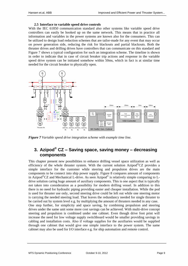
2.5 Interface to variable speed drive controls
With the IEC 61850 communication standard also other systems like variable speed drive
controllers can easily be hooked up on the same network. This means that in practice all
information and variables in the power systems are known also for the consumers. This can
be utilized to design load reduction schemes that are tailor-made for any event that may occur
on power generation side, reducing the risk for blackouts and partial blackouts. Both the
thruster drives and drilling drives have controllers that can communicate on this standard and
Figure 7 shows a typical configuration for such an integration scheme. The timeline is shown
in order to indicate that in case of circuit breaker trip actions and response in the variable
speed drive system can be initiated somehow within 50ms, which in fact is at similar time
needed for the circuit breaker to physically open.
G~
G~
~~ ~
M~
Thruster #x
Thr. Ctrl(PLC)
Thr. Aux. SwBd
Drill. Aux. SwBd
IEC
61
85
0
IEC
61
85
0
Drill Ctrl(PLC)
~
~ ~
Drill Drv.#x
Drill Ctrl(PLC)
~
Drill Drv. #x
~
Drill Drv.#x
~
Drill Drv. #x
M~
M~
M~
M~
IEC
61
85
0
P
P
P
P PP PPPPP
10ms
VSD Controller
Task
cycle & execution
time
Data
transfer
time
20ms 2ms 10ms
DTC
responds
VSD
MV SwBd; Gen. Cubical
GOOSE
delay
Brk
Trip
REM
Relay
output
daelay
CB open
delay
Figure 7 Variable speed drive integration scheme with example time line.
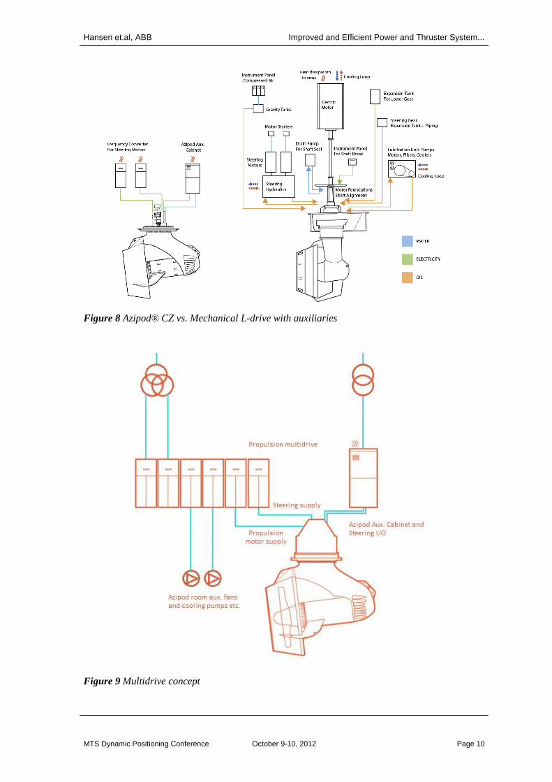
3. Azipod® CZ – Saving space, saving money – decreasing components
This chapter present new possibilities to enhance drilling vessel space utilization as well as
efficiency of the whole thruster system. With the current solution Azipod®CZ provides a
simple interface for the customer while steering and propulsion drives are the main
components to be connect into ship power supply. Figure 8 compares amount of components
in Azipod®CZ and Mechanical L-drive. As seen Azipod
® is relatively simple comparing to L-
drive solution caring huge amount of auxiliary components. This is one aspect that is typically
not taken into consideration as a possibility for modern drilling vessel. In addition to this
there is no need for hydraulic piping providing easier and cheaper installation. While the pod
is used for thruster use only, second steering drive could be left out while one steering motor
is carrying the needed steering load. That leaves the redundancy needed for single thruster to
be carried out by system level e.g. by multiplying the amount of thrusters needed in any case.
One step further, for simplicity and space saving, by combining propulsion and steering
drives under the same unit some more cost savings can be achieved. With multi-drive concept
steering and propulsion is combined under one cabinet. Even though drive foot print will
increase the need for low voltage supply switchboard would be smaller providing savings in
cabling and installation costs. Also if voltage supplies for the auxiliaries would be supplied
through one cabinet that would give one simple interface to the power system. The same
cabinet may also be used for I/O interface e.g. for ship automation and remote control.
Hansen et.al, ABB Improved and Efficient Power and Thruster System...
MTS Dynamic Positioning Conference October 9-10, 2012 Page 10
Figure 8 Azipod® CZ vs. Mechanical L-drive with auxiliaries
Figure 9 Multidrive concept

Hansen et.al, ABB Improved and Efficient Power and Thruster System...
MTS Dynamic Positioning Conference October 9-10, 2012 Page 11
The Azipod® room itself requires also ventilation, normally provided with separate power
supplies that are typically supplied from auxiliary switchboard. By combining also these into
one multidrive some more savings in cabling in addition to installation work will be gained.
Cabling has a huge cost saving potential, since the low voltage switchboards are often distant
from the load; for example in semi-submersible rigs, they may be located at the main deck
while the thruster rooms with the auxiliary drives are down in the pontoons. With this
solution hundreds of meters of cables can be avoided. Beside to these, fans and pumps (if
needed) can be controlled according to the actual ventilation need at a time instead of running
them with full power continuously. As pumps and fans are dimensioned to the requirements
of full capacity; they are over dimensioned for the normal load requirements and hence
wasting energy if they are run at fixed speed. As the auxiliary basically are used all the time
in DP operations, the energy saving is significant if the load can be controlled with variable
speed.
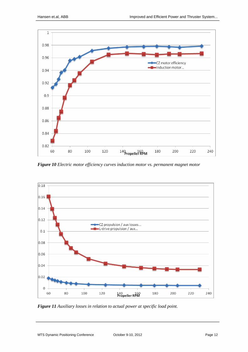
3.1 PM motor efficiency – High result with effective motors
Since the thruster load profile has a huge impact for the operating cost and fuel consumption,
the efficiency of the motor makes a direct impact on energy losses. Using permanent magnet
synchronous motors, the motor efficiency is higher than other feasible alternatives; and
together with the non-geared mechanical transmission from motor to propeller, the energy
efficiency from the electric supply to the shaft power is higher than in any geared thruster
concepts. Also, the heat produced by the motor is cooled directly into sea water, which
reduces the cooling demand within the thruster room. The following drill-ship concept
calculation shows the savings in real values.
An evaluation is made to compare yearly energy consumption of two different concepts of
propulsion with 6 x Azipod® CZ 4.5 MW thrusters and 6 x Mechanical L-drive 4.5 MW
thrusters. The operational profile is based on assumption that 5% of the yearly operation, the
vessel is in transit with full speed, while the remaining 95% is divided to DP operation
according to statistical multiyear share from similar units on DP vessel. Also 90% of the time
of DP operation the thrusters are operating with less than 100 rpm propeller speed (< 15% of
rated power). The result of that comparison is that the Azipod®CZ thruster is about 7% more
efficient on drill ship operation than an L-drive thruster; only considering the higher
efficiency of the permanent magnet motor compared to an induction motor, in particular at
low loads as shown in Figure 10. With 330 USD/MWh energy cost, this reduce the yearly
energy costs about 480,000 USD.
3.1 From small creeks into great river - PM auxiliary losses
As the Azipod®CZ has fewer auxiliary components than a mechanical L-drive thruster, there
is also a difference in their power consumption, which over time adds up to a significant
energy difference. The following model presents losses including also those additional
sources which often are disregarded, though important enough, when comparing the different
drive systems.
A mechanical thruster system will have high auxiliary power consumption. In particular in
part load operation (as most of the DP operation is) it is more dominant, see Figure 11.
Therefore, also such components as cooling fan lube oil pumps etc. were taken into account
on this analysis. The aim was to be able to compare on an ”apple to apple” basis – by
including also all auxiliary power loads; while the losses that are equivalent, such as
transformer losses, electric power transmission losses etc. were disregarded. As a conclusion
the analysis shows that there is potential of annual savings of thruster energy consumption of
3-7%, from the reduced auxiliary loads alone, by using the use of Azipod®CZ thrusters.
Hansen et.al, ABB Improved and Efficient Power and Thruster System...
MTS Dynamic Positioning Conference October 9-10, 2012 Page 12
Figure 10 Electric motor efficiency curves induction motor vs. permanent magnet motor
Figure 11 Auxiliary losses in relation to actual power at specific load point.

Hansen et.al, ABB Improved and Efficient Power and Thruster System...
MTS Dynamic Positioning Conference October 9-10, 2012 Page 13
3.2 Hydrodynamic Benefits
The Azipod®CZ has a non-geared mechanical transmission to the propeller, with a 7 degrees
tilt angle of the propeller shaft in order to reach a higher hydrodynamic efficiency. The tilt
angle leads to reduced interaction with the hull or pontoon and other thrusters, and reduces
the interaction to hull known as Coandă effect. Until recently, and still for some products
applied today, the mechanical L-drive thrusters have approached this problem by tilting the
nozzle, while the propeller shaft is horizontal. The difference in losses with a tilted nozzle
versus a tilted shaft line gives a difference in the thrust in the range of 4 to 8% for the same
shaft power load. Designs with horizontal shaft line, and non-tilted nozzle is not a viable
alternative, as the hull and thruster interaction losses may range to 10-30% of loss in the
thrust.
Figure 12 Azipod
® CZ with tilt angle
4. Concluding Remarks
The introduction of the IEC 61850 communication standard into marine power systems opens
many new ways of optimizing the total performance of power systems for marine vessels. For
DP class drilling vessels the standard enables fast and accurate communication between the
primary protection system and upper level protection systems (as PMS and DGMS) for the
power plant. For shipyards it means less cabinets and less wiring. For the operators it means
more accurate and faster protection functionality, which will reduce stress on component in a
failure mode situation. Further integration with variable speed drive controllers which
communicates directly on the same communication network, enables possibilities for fast and
accurate load reduction schemes, in case of power plant and generator failures.
It is shown that the efficiency of an Azipod®CZ thruster is better than that of a mechanical
thruster considering the various factors as electric motor type, auxiliary power consumption,
mechanical transmission, tilting of the propeller shaft, and hydrodynamic considerations. The
potential of energy saving and possible reduced installed power capacity depends on many
factors, and should be checked from case to case. We have in this article highlighted the
characteristics of the Azipod®CZ thruster with possibilities for energy and space saving. A
feasible and obtainable reduction in thruster energy usage in the order of 15% has been
shown, by using Azipod®CZ compared to mechanical thrusters. This is a result of electrical
and hydrodynamic efficiency; and being dependent on the thruster load profile.
References [1] Special Report IEC 61850; ABB Review; 2010; ISSN: 1013-3119
[2] Tiainen, L, Jehkonen, T., Hansen, J.F.; Simplifying Energy Efficiency; Generations
Magazine; Issue 1 -2012; ABB Marine and Cranes; 2012.