Dynamic Depth of Field on Live Video Streams: A Stereo ...
9
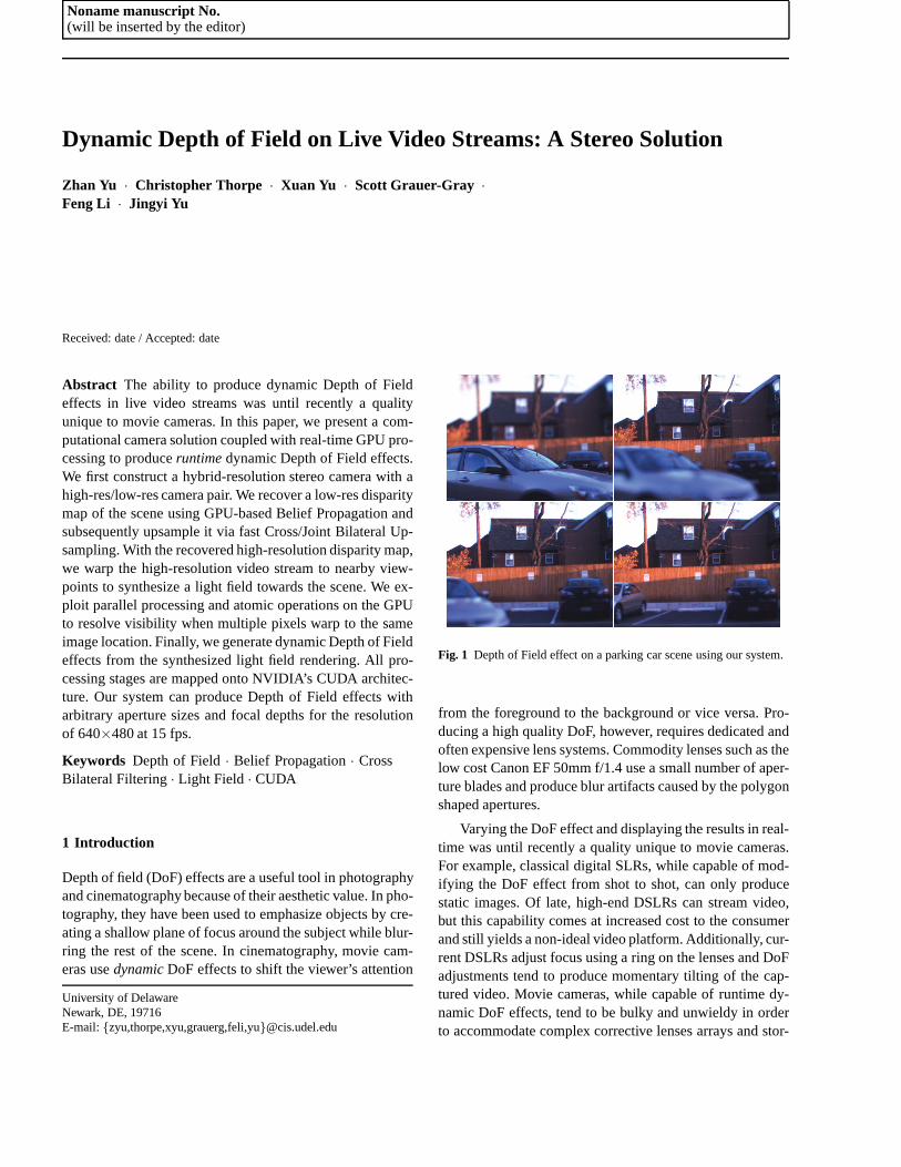
Noname manuscript No. (will be inserted by the editor) Dynamic Depth of Field on Live Video Streams: A Stereo Solution Zhan Yu · Christopher Thorpe · Xuan Yu · Scott Grauer-Gray · Feng Li · Jingyi Yu Received: date / Accepted: date Abstract The ability to produce dynamic Depth of Field effects in live video streams was until recently a quality unique to movie cameras. In this paper, we present a com- putational camera solution coupled with real-time GPU pro- cessing to produce runtime dynamic Depth of Field effects. We first construct a hybrid-resolution stereo camera with a high-res/low-res camera pair. We recover a low-res disparity map of the scene using GPU-based Belief Propagation and subsequently upsample it via fast Cross/Joint Bilateral Up- sampling. With the recovered high-resolution disparity map, we warp the high-resolution video stream to nearby view- points to synthesize a light field towards the scene. We ex- ploit parallel processing and atomic operations on the GPU to resolve visibility when multiple pixels warp to the same image location. Finally, we generate dynamic Depth of Field effects from the synthesized light field rendering. All pro- cessing stages are mapped onto NVIDIA’s CUDA architec- ture. Our system can produce Depth of Field effects with arbitrary aperture sizes and focal depths for the resolution of 640×480 at 15 fps. Keywords Depth of Field · Belief Propagation · Cross Bilateral Filtering · Light Field · CUDA 1 Introduction Depth of field (DoF) effects are a useful tool in photography and cinematography because of their aesthetic value. In pho- tography, they have been used to emphasize objects by cre- ating a shallow plane of focus around the subject while blur- ring the rest of the scene. In cinematography, movie cam- eras use dynamic DoF effects to shift the viewer’s attention University of Delaware Newark, DE, 19716 E-mail: {zyu,thorpe,xyu,grauerg,feli,yu}@cis.udel.edu Fig. 1 Depth of Field effect on a parking car scene using our system. from the foreground to the background or vice versa. Pro- ducing a high quality DoF, however, requires dedicated and often expensive lens systems. Commodity lenses such as the low cost Canon EF 50mm f/1.4 use a small number of aper- ture blades and produce blur artifacts caused by the polygon shaped apertures. Varying the DoF effect and displaying the results in real- time was until recently a quality unique to movie cameras. For example, classical digital SLRs, while capable of mod- ifying the DoF effect from shot to shot, can only produce static images. Of late, high-end DSLRs can stream video, but this capability comes at increased cost to the consumer and still yields a non-ideal video platform. Additionally, cur- rent DSLRs adjust focus using a ring on the lenses and DoF adjustments tend to produce momentary tilting of the cap- tured video. Movie cameras, while capable of runtime dy- namic DoF effects, tend to be bulky and unwieldy in order to accommodate complex corrective lenses arrays and stor-
Transcript of Dynamic Depth of Field on Live Video Streams: A Stereo ...
Noname manuscript No.(will be inserted by the editor)
Dynamic Depth of Field on Live Video Streams: A Stereo Solution
Zhan Yu · Christopher Thorpe · Xuan Yu · Scott Grauer-Gray ·
Feng Li · Jingyi Yu
Received: date / Accepted: date
Abstract The ability to produce dynamic Depth of Fieldeffects in live video streams was until recently a qualityunique to movie cameras. In this paper, we present a com-putational camera solution coupled with real-time GPU pro-cessing to produceruntime dynamic Depth of Field effects.We first construct a hybrid-resolution stereo camera with ahigh-res/low-res camera pair. We recover a low-res disparitymap of the scene using GPU-based Belief Propagation andsubsequently upsample it via fast Cross/Joint Bilateral Up-sampling. With the recovered high-resolution disparity map,we warp the high-resolution video stream to nearby view-points to synthesize a light field towards the scene. We ex-ploit parallel processing and atomic operations on the GPUto resolve visibility when multiple pixels warp to the sameimage location. Finally, we generate dynamic Depth of Fieldeffects from the synthesized light field rendering. All pro-cessing stages are mapped onto NVIDIA’s CUDA architec-ture. Our system can produce Depth of Field effects witharbitrary aperture sizes and focal depths for the resolutionof 640×480 at 15 fps.
Keywords Depth of Field· Belief Propagation· CrossBilateral Filtering· Light Field · CUDA
1 Introduction
Depth of field (DoF) effects are a useful tool in photographyand cinematography because of their aesthetic value. In pho-tography, they have been used to emphasize objects by cre-ating a shallow plane of focus around the subject while blur-ring the rest of the scene. In cinematography, movie cam-eras usedynamic DoF effects to shift the viewer’s attention
University of DelawareNewark, DE, 19716E-mail:{zyu,thorpe,xyu,grauerg,feli,yu}@cis.udel.edu
Fig. 1 Depth of Field effect on a parking car scene using our system.
from the foreground to the background or vice versa. Pro-ducing a high quality DoF, however, requires dedicated andoften expensive lens systems. Commodity lenses such as thelow cost Canon EF 50mm f/1.4 use a small number of aper-ture blades and produce blur artifacts caused by the polygonshaped apertures.
Varying the DoF effect and displaying the results in real-time was until recently a quality unique to movie cameras.For example, classical digital SLRs, while capable of mod-ifying the DoF effect from shot to shot, can only producestatic images. Of late, high-end DSLRs can stream video,but this capability comes at increased cost to the consumerand still yields a non-ideal video platform. Additionally,cur-rent DSLRs adjust focus using a ring on the lenses and DoFadjustments tend to produce momentary tilting of the cap-tured video. Movie cameras, while capable of runtime dy-namic DoF effects, tend to be bulky and unwieldy in orderto accommodate complex corrective lenses arrays and stor-

2 Zhan Yu et al.
Low Resolution
Stream
High Resolution
Stream
Low Resolution
Depth Map
High Resolution
Depth MapLight Field
Depth MapEstimation
Bilateral Upsampling Synthesis
Light Field RenderingRendering
DoF
Fig. 2 The imaging hardware and the processing pipeline of our dynamic DoF video acquisition system. All processing modules are implementedon NVIDIA’s CUDA to achieve real-time performance.
age media. Further, fully servoed studio lenses such as theCanon DIGI SUPER 25 XS can cost tens of thousands ofdollars.
Our work is inspired by the recent light field imagingsystems [27,11,21,22,9]. The Stanford light field cameraarray [23,24,19,20] is a two dimensional grid composed of128 1.3 megapixel firewire cameras which stream live videoto a stripped disk array. The large volume of data generatedby this array forces the DoF effect to be rendered in postprocessing rather than in real-time. Furthermore, the systeminfrastructure such as the camera grid, interconnects, andworkstations are bulky, making it less suitable for on-sitetasks. The MIT light field camera array [25] uses a smallergrid of 64 1.3 megapixel usb webcams instead of firewirecameras and is capable of synthesizing real-time dynamicDoF effects. Both systems, however, still suffer from spatialaliasing because of the baseline between neighboring cam-eras. The camera spacing creates appreciable differences be-tween the pixel locations of the same scene point in neigh-boring cameras producing an aliasing effect at the DoF bound-ary when their images are fused.
In an attempt to reduce aliasing artifacts in light-fieldbased solutions, Ng [13] designed a light field camera thatcombines a single DSLR with a microlenslet array. Eachlenslet captures the scene from a different viewpoint and thelenslet array effectively emulates a camera array. By usinga large number of densely packed lenslets, one can signifi-cantly reduce the spatial aliasing artifacts. It also, however,comes at the cost of reduced resolution for each light fieldview. A light field camera is typically paired with an ultra-high-resolution static DSLR and is therefore not applicableto video streaming.
Instead of using either a camera array or a microlensletarray, we develop a novel hybrid stereo-lightfield solution.Our goal is to first recover a high-resolution disparity map ofthe scene and then synthesize a virtual light field for produc-ing dynamic DoF effects. Despite recent advances in stereomatching, recovering high-resolution depth/disparity maps
from images is still too expensive to perform in real-time.We, therefore, construct a hybrid-resolution stereo camerasystem by coupling a high-res/low-res camera pair. We re-cover a low-res disparity map and subsequently upsampleit via fast cross bilateral filters. We then use the recoveredhigh-resolution disparity map and its corresponding videoframe to synthesize a light field. We implement a GPU-based disparity warping scheme and exploit atomic opera-tions to resolve visibility. To reduce aliasing, we presentanimage-space filtering technique that compensates for spatialundersampling using MIPMAPPING. Finally, we generatedynamic DoF effects using light field rendering. The com-plete processing pipeline is shown in Figure 2.
We map all processing stages onto NVIDIA’s CUDA ar-chitecture. Our system can produce DoF effects with arbi-trary aperture sizes and focal depths for the resolution of640×480 at 15 fps, as shown in the gsupplementary video.This indicates that if we capture the video streams at thesame frame rate, we can display the refocused stream si-multaneously. Our system thus provides a low-cost, com-putational imaging solution for runtime refocusing, an ef-fect that is usually the domain of expensive movie cameraswith servo-controlled lenses. Experiments on both indoorand outdoor scenes show that our framework can robustlyhandle complex, dynamic scenes and produce high qualityresults. Figure 1 shows the result of our system on a parkinglot scene.
2 Hybrid-Resolution Stereo Camera
We first construct a hybrid stereo camera for recovering high-resolution disparity map in real-time. Our system uses thePointgrey Flea2 camera pair to produce onehigh-resolutioncolor video stream and onelow-resolution gray-scale videostream. We synchronize frame capture to within 125µs byusing the Pointgrey camera synchronization package. A uniquefeature of our approach is coupling our Hybrid-Resolution

Dynamic Depth of Field on Live Video Streams: A Stereo Solution 3
High-Frequency Processing Module
Mid/Low Frequency
Disparity Map
Mid Res.
Disparity MapMid Res.
Image
High Res.
Image
Low Res.
Disparity Map
High Res.
Disparity Map
Edge
Map
Edge
Disparity Map
High Pass Filtering
DownsamplingCross Bilateral
Filtering
Cross Bilateral
Filtering
Upsampling
Replacing
Mid- and Low- Frequency Processing Module
Fig. 3 Our fast cross bilateral upsampling scheme synthesizes a high-resolution disparity map from the low-resolution BP stereo matching resulton CUDA.
Stereo Camera with a CUDA processing pipeline for real-time DoF synthesis. Sawhney et al. proposed a hybrid stereocamera for synthesis of very high resolution stereoscopicimage sequences [15]. Li et al. also proposed a hybrid cam-era for motion deblurring and depth map super-resolution[10]. Our configurations, however, have many more advan-tages. First and foremost, it provides a multi-resolution stereomatching solution that can achieve real-time performance(Section 3). Second, the lower bandwidth requirement alsoallows our system to be implemented for less expense on agreater number of platforms. Stereo systems that stream twovideos at 15 fps and 640× 480 resolution can produce upto 27.6 MB of data per second. By comparison, our hybrid-resolution stereo camera only produces slightly more thanhalf that rate of data. Although our current implementationuses Firewire cameras, the low bandwidth demands of oursolution make it possible to use a less expensive and morecommon alternative like USB 2.0, even for streaming higherresolutions such as 1024× 768. Finally, compared to off-the-shelf stereo cameras such as Pointgrey’s Bumblebee, oursystem has several advantages in terms of image quality,cost, and flexibility. For example, the form factor of the Bum-blebee forces its lenses to be small and it produces imagewith severe radial distortion. Our system is also less expen-sive ($1500 vs. $4000), and our setup allows us to dynam-ically adjust the camera baseline to best fit different typesof scenes unlike the Bumblebee. We calibrate the stereo pairusing a planar checker board pattern the algorithm outlinedby Zhang [28]. It is not necessary, however, that the calibra-tion be absolutely accurate as the disparity map is recoveredfrom a severely downsampled image pair. Our experimentshave shown that disparity map recovery using belief prop-agation on the low-resolution image pair is not affected byslight changes in the camera pair geometry. The intensitycalibration on the camera pair is performed prior to cap-ture via histogram equalization. The mappings for these pro-
cesses are retained and applied to each incoming frame priorto stereo matching.
3 Real-time Stereo Matching
In order to efficiently generate a high-resolution disparitymap from the input low-res/high-res image pairs, we imple-ment a GPU-based stereo matching algorithm on CUDA.
3.1 CUDA Belief Propagation
Stereo matching is a long standing problem in computer vi-sion [16]. Global methods based on belief propagation (BP)[18] and graph-cut [5,1] have been known to produce highlyreliable and accurate results. These methods, however, aremore expensive when compared to local optimization meth-ods such as dynamic programming. Fortunately, BP lendsitself well to parallelism on the GPU [2,4], where the corecomputations can be performed at every image pixel in par-allel on the device.
We utilize the methods presented by Felzenwalb [3] tospeed up our implementation without affecting the accuracy:we use a hierarchical implementation to decrease the num-ber of iterations needed for message value convergence; weapply a checkerboard scheme to split the pixels when pass-ing messages in order to reduce the number of necessary op-erations and halve the memory requirements; and we utilizea two-pass algorithm to reduce the running time to generateeach message fromO(n2) to O(n) using the truncated linearmodel for data/smoothness costs.
Our CUDA BP implementation uses five separate ker-nels, whereas the CPU only calls the appropriate kernels andadjusts the current parameters/variables. A kernel is usedtoperform each of the following steps in parallel, with eachthread mapping to computations at a distinct pixel:

4 Zhan Yu et al.
Fig. 4 Comparison of the result with(right) and without(left) high fre-quency compensation.
1. Compute the data costs for each pixel at each possibledisparity at the bottom level.
2. Iteratively compute the data cost for each pixel at eachsucceeding level by aggregating the appropriate data costsat the proceeding level.
3. For each level of the implementation:(a) Compute the message values at the current ‘checker-
board’ set of pixels and pass the values to the alterna-tive set. Repeat fori iterations, alternating betweenthe two sets.
(b) If not at the bottom level, copy message values ateach pixel to corresponding pixels of the succeedinglevel.
4. Compute the disparity estimate at each pixel using thedata cost and current message values corresponding toeach disparity.
Table 1 shows the performance of our algorithm on someof the Middlebury datasets at different resolutions. Despitethe acceleration on the GPU, we find that it is necessary touse the lower resolution images (320×240 or lower) as in-puts to our stereo algorithm in order to achieve real-timeperformance.
Data setsResolutions
128×96 320×240 640×480Teddy 13ms 78 ms 446 ms
Tsukuba 8ms 55ms 357 msCones 11ms 69 ms 424 ms
Table 1 Performance of our CUDA stereo matching at different reso-lutions. Note that the number of disparity levels is proportionally scaledto the resolution. The levels of belief propagation are all set to 5 anditerations per level are all set to 10.
In our experiments described in the rest of the paper, wefirst smooth these low-resolution image pairs using a Gaus-sian filter whereσ equals 1.0, then process them using ourimplementation with a disparity range from 0 to 35, maxi-mum data cost and smoothness costs of 15.0 and 1.7, respec-tively, a data cost weight of 0.7 in relation to the smoothnesscost, with 5 levels of belief propagation and 10 iterations
Ground Truth Bicubic Gaussian Ours
Fig. 5 Comparison of our method and other upsampling schemes onsynthesize data. Both patches in the disparity map are upsampled froma resolution of 30×25 to 450×375.
per level. Each kernel is processed on the GPU using threadblock dimensions of 32×4.
3.2 Fast Cross Bilateral Upsampling
Given a low-resolution disparity mapD′ and a high-resolutionimage I, we intend to recover a high-resolution disparitymapD using cross bilateral filters [26], where we apply aspatial Gaussian filter toD′ and a color-space Gaussian fil-ter toI. Assumingp andq are two pixels inI; W is the filterwindow size;Ip andIq are the color ofp andq in I; andq′
is the corresponding pixel coordinate ofq in D′. We also useσc andσd as constants to threshold the color difference andfilter size. We compute the disparity of pixelDp as:
Dp =∑q∈W Gd(p,q)Gc(p,q)D′
q
Kp, (1)
whereKp =∑q∈W Gd(p,q)Gc(p,q), Gd(p,q)= exp(−||p−q||σd
),
andGc(p,q) = exp(−||Ip−Iq||σc
).The complexity of cross bilateral upsampling (CBU) is
O(NW ) whereN is the output image size andW is the filterwindow size. Therefore the dominating factor to the process-ing time is the number of pixels that need to be upsampled,i.e., the resolution of the high-res image in the brute-forceimplementation.
To accelerate our algorithm, we implement a fast CBUscheme that effectively reduces the pixels to be upsampled.Pariset al. [14] have shown that the mid and low frequencycomponents of an image remain approximately the samewhen downsampled. We therefore treat the high-frequencyand the mid- and low- frequency components separately.Our method first applies a Gaussian high-pass filter to iden-tify the pixels of high frequency inI and then uses a standardcross bilateral filter to estimate the disparity values at onlythese pixels. We store the resulting disparity map asDhigh.We call this step the high-frequency processing module. Inparallel, we downsample the color image to mid-resolutionImid , apply CBU betweenD′ and Imid to obtain the mid-res disparity mapDmid ; and subsequently upsampleDmid to

Dynamic Depth of Field on Live Video Streams: A Stereo Solution 5
Bicubic Color ImageOur Approach
Fig. 6 Comparison between our method and bicubic upsampling onreal scenes. The disparity map is upsampled from 320×240 to 640×480. Our method preserves sharp edges and maintains smoothness,which is critical to reliable DoF synthesis.
Dhigh using standard bilinear upsampling. We call this stepthe mid- and low- frequency processing module. Finally, weperform high frequency compensation byreplacing the dis-parity value at the identified high frequency pixelsI withDhigh. Figure 3 shows the complete processing pipeline ofour algorithm. Compared with standard CBU, our schemeonly needs to upsample a small portion of the pixels andhence is much faster.
3.3 CUDA Implementation.
We developed a GPU implementation of our algorithm onthe CUDA architecture to tightly integrate with our CUDABP stereo mapping algorithm. In our experiments, we foundthat it is most efficient to assign one thread to upsample eachpixel in the disparity map. To further evaluate the through-put of our implementation, we upsampled 128×128 dispar-ity maps with 1280×1280 color images. Our implementa-tion achieves a processing speed of 22 ms per frame or 14ms per megapixel with a 5× 5 filter window, a significantspeedup to the CPU-based scheme [6] (which was 2 secondsper megapixel).
To measure the accuracy of our scheme, we performedexperiments using various stereo data sets. In Figure 4, weshow using the Teddy data set that reintroducing high fre-quency compensation produces sharper edges and smoothersurfaces. Figure 5 illustrates our results in three regionsonthe Teddy data set. They are upsampled from 30× 25 to450×375. Compared with standard bicubic or Gaussian up-sampling, our method preserves fine details near the edges.It is important to note that preserving edges while removingnoise in the disparity map is crucial to our DoF synthesisas DoF effects are most apparent near the occlusion bound-aries. Figure 6 gives the results on an indoor scene usingbicubic upsampling and our method. To further measure theaccuracy, we compared our estimation with the ground truthby computing the mean squared errors over all pixels. Table2 compares the error incurred by our method under differentupsampling scales on a variety of Middlebury stereo data
(a) (b)
(c) (d)
Fig. 7 Comparing results generated by image space blurring (a, c) andour light field synthesis method (b, d). Our approach effectively re-duces both the intensity leakage (a) and boundary discontinuity (c) ar-tifacts.
sets, and the results show that our method is reliable andaccurate even with very high upsampling scales.
Data setsUpsampling Scales
20×20 10×10 5×5 2×2Teddy 31.14 10.96 5.24 3.92Plastic 20.79 11.56 6.50 7.29
Monopoly 30.91 9.73 4.71 3.45Books 26.01 15.60 9.12 6.25Baby2 11.09 5.11 3.35 2.02Aloe 73.96 23.14 11.36 4.49Cones 49.42 33.64 10.82 4.24
Art 67.40 24.70 8.70 4.67
Table 2 Mean squared errors of our upsampled disparity maps withdifferent upsampling factors on the Middlebury data sets.
4 Real Time DoF Synthesis
Once we obtain the high-resolution disparity map, we setout to synthesize dynamic DoF effects. Previous single im-age based DoF synthesis algorithms attempt to estimate thecircle of confusion at every pixel and then apply the spatiallyvarying blurs on the image. These methods produce strongbleeding artifacts at the occlusion boundaries, as shown inFigure 7. In computer graphics, the distributed ray tracingand the accumulation buffer techniques have long served asthe rendering method for dynamic DoF. Both approaches arecomputationally expensive as they either require tracing outa large number of rays or repeated rasterization of the scene.Furthermore, to apply ray-tracing or accumulation buffer in

6 Zhan Yu et al.
our application requires constructing a triangulation of thescene from the depth map, which would incur additionalcomputational cost.
In this paper, we adopt a similar approach to [27] by dy-namically generating a light field from the high-resolutionvideo stream and its depth stream, as shown in Figure 8.Our technique, however, differs in that we directly use thedisparity map for warping and filtering whereas [27] buildsupon the depth map. As follows, we briefly reiterate themain steps of this light-field based DoF rendering technique.
4.1 The Lens Light Field
The light field is a well known image based rendering tech-nique. It uses a set of rays commonly stored in a 2D array ofimages to represent a scene. Each ray in the light field canbe indexed by an integer 4-tuple (s, t,u,v), where (s, t) is theimage index and (u,v) is the pixel index within a image.
Our first step generates a light field from the stereo pair.The high resolution camera in our stereo pair is used as thereference cameraR00.
To synthesize the light field, we use the high-resolutioncamera in our stereo pair as the reference cameraR00 (i.e.,(s, t) = (0,0)). We can then easily find all rays that passthrough a 3D pointA in terms of its disparityγ from thereference view. AssumingA’s image is at pixel(u0,v0) inthe reference camera, we can compute its image (pixel coor-dinate) in any light field cameraRst as:
(u,v) = (u0,v0)+ (s, t) · γ (2)
We useLout(s, t,u,v) to represent the out-of-lens lightfield andLin(x,y,s, t) to represent the in-camera light field.The image formed by a thin lens is proportional to the irradi-ance at a pixela [17], which can be computed as a weightedintegral of the incoming radiance through the lens:
a(x,y)≈ ∑(s,t)
Lin(x,y,s, t)cos4φ (3)
To map the in-lens light field to the out-of-lens lightfield, it is easy to verify that pixela(x,y) on the sensor mapsto pixel(u0,v0) = (w−x,h−y) in R00. Therefore, if we wantto focus at the scene depth whose corresponding disparity isγ f , we can find the pixel index in cameraRst using Equa-tion 2. The irradiance ata can be approximated as:
a(x,y) = ∑(s,t)
Lout(s, t,u0+ s · γ f ,v0+ t · γ f ) · cos4φ
To estimate the attenuation cos4 φ term, we can directly com-pute cos4 φ for each ray(s, t,u,v). Notice that the ray has di-rection(s, t,1). Therefore, we can compute cos4 φ = 1
(s2+t2+1)2.
XY
Plane
ST
Plane
UV
Plane
Focal
Plane
(u0, v0)p(x, y)
Color Disparity
Dynamic Light Field Generation
Fig. 8 We synthesize an in-lens light field (left) from the recoveredhigh-resolution color image and disparity map (right).
4.2 CUDA Implementation
To synthesize the light field from the reference cameraR00
and its disparity map, we warp it onto the rest light fieldcameras using Equation 2. A naive approach would be todirectly warp the RGB color of each pixela(u0,v0) in R00
onto other light field cameras. Specifically, usinga’s dispar-ity value, we can directly compute its target pixel coordinatein cameraRst using Equation 2. Since the CUDA architec-ture supports parallel write, we can simultaneously warp allpixels inR00 onto other light field cameras.
Although the warping process is straight forward, atten-tion needs to be paid to the correctness of the light field.Since multiple pixels inR00 may warp to the same pixela inthe light field cameraRst , a depth comparison is necessaryto ensure the correct visibility. Thus each light field cam-era requires an additional depth buffer. To avoid write-writeconflicts in the warping process, we use atomic operations.However, current graphics hardware cannot handle atomicoperations on both color and depth values at the same time.To resolve this issue, we only choose to warp the disparityvalue. We can easily index the RGB value for each light fieldray using the stored disparity value and the camera param-eters. This solution requires less video memory as the RGBvalue does not need to be stored in the light field.
Due to speed requirements, we can only render a smalllight field with 36 to 48 cameras at a 640×480 image reso-lution. The low spatial resolution leads to strong aliasingar-tifacts due to undersampling. Since our reference view doesnot contain information from the occluded regions, the warpedlight field camera images will contain holes.
To reduce the image artifacts caused by undersamplingand occlusions, we develop a simple technique similar to thecone tracing method to pre-filter the reference view [7]. Ourmethod is based on the observation that out-of-focus regionsexhibit most severe aliasing artifacts and occlusion artifactssince they blend rays corresponding to different 3D points.Our method compensates for undersampling by first blur-

Dynamic Depth of Field on Live Video Streams: A Stereo Solution 7
Focus at
Foreground
Lens
Kernels
Ground
TruthOurs
Image
Space
Lens
Focus at
Background
Ground
TruthOurs
Image
Space
Ab Ab
Fig. 9 Illustrations of two types of boundary artifacts. See Section 4.3for details.
ring the out-of-focus rays and then blending them. A similarconcept has been used in the Fourier slicing photographytechnique for generating a band-limited light field [12].
To simulate low-pass filtering in light field rendering, wefirst generate a Mipmap from the reference image using a3× 3 Gaussian kernel [8]. We then integrate the GaussianMipmap into the light field ray querying process.
4.3 Our Technique vs. Single-Image Blurring
Compared with single-image methods that apply spatiallyvarying blurs, our light field based DoF synthesis techniquesignificantly reduces two types of boundary artifacts. In in-stances where the camera focuses at the foreground, the groundtruth result should blend points on the background. Con-versely, single-image filtering techniques use a large kernelto blend the foreground and background pixels and hence,produce theintensity leakage artifact. Consider a pointAb
lying on the background near the boundary, as shown in Fig-ure 9. Our method attempts to blend rays originating fromthe background. Due to occlusions, it can only access a por-tion of them. Even if the background has consistent color ortexture, our technique still produces reasonable approxima-tions.
In instances where the camera focuses on the background,the ground truth result should blend both the foreground andbackground points. Single-image filtering techniques, how-ever, would considerAb in focus and hence directly use itscolor as the pixel’s color. In this case, the transition fromthe foreground to the background appears abrupt, causingtheboundary discontinuity artifacts. Consider a pointAb onthe background near the occlusion boundary in the imageas shown in Figure 9. Since rays originating from both theforeground and background are captured by our synthesizedlight field, our technique will produce the correct result.
Figure 7 compares the rendering results using our methodand the single-image filtering approach on an indoor scene.
(a) (b)
(c) (d)
Fig. 10 Results of synthesizing changing aperture sizes. The aperturesize gradually decreases from (a) to (d).
Our technique exhibits fewer visual artifacts compared tothe single-image filtering method, especially near the bound-ary of the girl. When examining the boundary of the sweater,the single-image method blurs the black sweater regions intothe background and thus causes color bleeding, whereas ourtechnique prevents such leakage. When focusing at the back-ground, the single-image method exhibits discontinuous tran-sitions from the girl to the background while our methodpreserves the smooth transition.
Our method also correctly preserves the boundaries be-tween the in-focus and out-of-focus regions when synthesiz-ing changing aperture sizes. As shown in Figure 10, we fixthe focus at the woman. With the aperture fully open in (a),the blur level decreases as we decrease the aperture size.
5 Results and Discussions
Our hybrid-resolution stereo system is connected to a workstation through a single PCI-E Firewire card. The worksta-tion is equipped with a 3.2GHz Intel Core i7 970 CPU, 4GBmemory and an NVIDIA Geforce GTX 480 Graphic Cardwith 1.5GB memory. We implement all three processing mod-ules (the disparity map estimation, fast CBU, dynamic DoFrendering) using NVIDIA’s CUDA 3.1 with compute capa-bility 2.0. Our system runs at the resolution of 640× 480with 15 fps.
We have conducted extensive experiments on both in-door and outdoor scenes. Some of our video results (livecapture) can be found in the supplementary video. We ex-pect to submit a demo to CGI ’11 to demonstrate our sys-tem. A crucial step in our real-time stereo matching moduleis choosing the proper parameters (e.g., the weight for thesmooth/compatible terms of the energy function) to fit dif-

8 Zhan Yu et al.
(a) (b) (c) (d)
Fig. 11 Screen captures of live video streams produced by our systemon both indoor (top two rows) and outdoor (bottom row) scenes.
ferent types of scenes (indoor vs. outdoor). We have devel-oped an interface to dynamically change the parameters, asshown in the supplementary video.
We first demonstrate our system on indoor scenes withcontrolled lighting. Figure 11 row 1 shows four frames cap-tured by our system of a girl drinking coffee while reading.The coffee cup in the scene is textureless and very smooth.Our fast CBU scheme, however, still preserves the disparityedges, as shown in Figure 11 row 1. We then dynamicallychange the depth of the focal plane: column (a) and column(d) focus on the front of the table, column (b) focuses onthe girl, and column (c) focuses on the background. Noticehow the blur varies and the in-focus regions fade into theout-of-focus regions.
Figure 11 row 2 displays a scene of a girl moving a toycar on a table. The surface of the car is specular, and thebackground and car have similar colors, making it challeng-ing to prevent the disparity of the background from mergingwith the disparity of the car. Moreover, the motion of the caris towards the camera, causing the body of the car to haveseveral different disparities. This makes labeling each pixelusing stereo correspondence methods even more difficult.Nevertheless, our algorithm preserves the edges of the carwhen it is in focus and correctly blurs portions of the sceneoutside of the focal plane. Our system performs well indoorsbecause the background distance is often limited, thereforeallowing one baseline to produce accurate disparity labels
for the entire scene. In addition, artificially lit indoor sceneswith diffuse walls and surfaces tend to have moderate dy-namic range and have few poorly lit or saturated regions.
Indoor scenes undoubtedly aid the performance of oursystem. Our experiments on outdoor scenes, however, showpromising results as well. Row 3 of Figure 11 shows an out-door sequence with a distant background under dynamicallyvarying lighting conditions. Notice that in column (a), theimage is brighter than the rest of the frames in the sequenceand the background contains noticeable shadows. In addi-tion to incoherent illumination, large portions of the scenesuch as the sky and the ground are textureless, making itdifficult to achieve robust stereo matching. Since our sys-tem allows us to dynamically change the camera baseline,we use its real-time feedback to tune the parameters and in-crease the camera baseline to obtain a satisfactory disparitymap, as shown in the supplementary video. The use of largebaseline may lead to holes near the occlusion boundaries onfull-resolution images. These holes are, however, less sig-nificant in low-resolution stereo pairs and our upsamplingscheme is able to borrow information from the color imageto fill in the holes. The extracted frames show that we areable to correctly change the focus between the moving tar-gets in both foreground and background.

Dynamic Depth of Field on Live Video Streams: A Stereo Solution 9
6 Conclusion and Future Work
We have presented an affordable stereo solution for produc-ing high quality live DoF effects. Our system shows promis-ing results on indoor and outdoor scenes although it still hasseveral limitations. First, 15 fps is a low frame rate and ourresolution of 640×480 precludes our system from immedi-ately being used in high quality HD video applications. Us-ing multiple GPUs may address this problem as they allowgreater exploitation of inherent parallelism in our computa-tional pipeline. Second, although the high quality sensor andlens system on our camera pair significantly reduces imagenoise and optical distortions, this comes with a higher price.While less expensive than existing commercial movie cam-eras, our system is still twice the cost of most base levelvideo cameras. Integrating existing real-time techniquestocorrect optical distortions and sensor noise into our pipelinewould make it feasible to use lower cost webcams instead ofthe firewire Flea cameras.
Our future efforts include adapting our system to func-tional applications such as privacy protected surveillance.We plan to demonstrate the usefulness of our system in ur-ban spaces to limit the focal plane to public areas, e.g., thesidewalks, while blurring more distant private areas like theinterior of homes. Current urban surveillance networks areaugmented with real-time recognition algorithms to detectillegal activity. When illegal activity is detected, our systemcould provide more information to law enforcement by re-moving the DoF effect using the stored disparity map streamfor subsequent scene reconstruction. We can also leveragefuture gains in ubiquitous computing to produce a truly mo-bile platform which utilizes, for example, two camera phonesfor producing DSLR quality imagery.
7 Acknowledgement
This project was partially supported by the National ScienceFoundation under grants IIS-CAREER-0845268 and IIS-RI-1016395, and by the Air Force Office of Scientific Researchunder the YIP Award.
References
1. Boykov, Y., Veksler, O., Zabih, R.: Fast approximate energy min-imization via graph cuts. PAMI, IEEE Transactions on23(11),1222 –1239 (2001)
2. Brunton, A., Shu, C., Roth, G.: Belief propagation on the gpu forstereo vision. In: Computer and Robot Vision, The 3rd CanadianConference on (2006)
3. Felzenszwalb, P., Huttenlocher, D.: Efficient belief propagation forearly vision. In: CVPR (2004)
4. Grauer-Gray, S., Kambhamettu, C., Palaniappan, K.: Gpu imple-mentation of belief propagation using cuda for cloud trackingand reconstruction. In: Pattern Recognition in Remote Sensing
(PRRS 2008), 2008 IAPR Workshop on, pp. 1 –4 (2008). DOI10.1109/PRRS.2008.4783169
5. Kolmogorov, V., Zabin, R.: What energy functions can be mini-mized via graph cuts? PAMI, IEEE Transactions on26(2), 147–159 (2004)
6. Kopf, J., Cohen, M.F., Lischinski, D., Uyttendaele, M.: Joint bi-lateral upsampling. In: SIGGRAPH (2007)
7. Lee, S., Eisemann, E., Seidel, H.P.: Depth-of-field rendering withmultiview synthesis. In: SIGGRAPH Asia (2009)
8. Lee, S., Kim, G.J., Choi, S.: Real-time depth-of-field renderingusing anisotropically filtered mipmap interpolation. IEEETrans-actions on Visualization and Computer Graphics15(3), 453–464(2009)
9. Levin, A., Hasinoff, S.W., Green, P., Durand, F., Freeman, W.T.:4d frequency analysis of computational cameras for depth offieldextension. ACM Trans. Graph.28 (2009)
10. Li, F., Yu, J., Chai, J.: A hybrid camera for motion deblurringand depth map super-resolution. In: Computer Vision and PatternRecognition,CVPR 2008. IEEE Conference on, pp. 1 –8 (2008)
11. Mcmillan, L., Yang, J.C., Yang, J.C.: A light field camerafor im-age based rendering (2000)
12. Ng, R.: Fourier slice photography. In: SIGGRAPH (2005)13. Ng, R., Levoy, M., Brdif, M., Duval, G., Horowitz, M., Hanrahan,
P.: Stanford tech report ctsr 2005-02 light field photography witha hand-held plenoptic camera
14. Paris, S., Durand, F.: A fast approximation of the bilateral filterusing a signal processing approach. Int. J. Comput. Vision81(1),24–52 (2009)
15. Sawhney, H.S., Guo, Y., Hanna, K., Kumar, R.: Hybrid stereocamera: an ibr approach for synthesis of very high resolutionstereoscopic image sequences. In: SIGGRAPH, pp. 451–460.Press (2001)
16. Scharstein, D., Szeliski, R.: A taxonomy and evaluationof densetwo-frame stereo correspondence algorithms. Int. J. Comput. Vi-sion47, 7–42 (2002)
17. Stroebel, L., Compton, J., Current, I., Zakia, R.: Photographic Ma-terials and Processes (1986)
18. Sun, J., Zheng, N.N., Shum, H.Y.: Stereo matching using beliefpropagation. PAMI, IEEE Transactions on25(7), 787 – 800 (2003)
19. Vaish, V., Levoy, M., Szeliski, R., Zitnick, C., Kang, S.B.: Re-constructing occluded surfaces using synthetic apertures: Stereo,focus and robust measures. In: CVPR (2006)
20. Vaish, V., Wilburn, B., Joshi, N., Levoy, M.: Using plane+ paral-lax for calibrating dense camera arrays. In: CVPR (2004)
21. Wang, H., Sun, M., Yang, R.: Space-time light field rendering.IEEE Transactions on Visualization and Computer Graphics13,697–710 (2007)
22. Wang, H., Yang, R.: Towards space: time light field rendering. In:I3D (2005)
23. Wilburn, B., Joshi, N., Vaish, V., Levoy, M., Horowitz, M.: High-speed videography using a dense camera array. In: CVPR (2004)
24. Wilburn, B., Joshi, N., Vaish, V., Talvala, E.V., Antunez, E., Barth,A., Adams, A., Horowitz, M., Levoy, M.: High performance imag-ing using large camera arrays. ACM Trans. Graph.24, 765–776(2005)
25. Yang, J.C., Everett, M., Buehler, C., McMillan, L.: A real-timedistributed light field camera. In: Proceedings of the 13th Euro-graphics workshop on Rendering, EGRW ’02, pp. 77–86 (2002)
26. Yang, Q., Yang, R., Davis, J., Nister, D.: Spatial-depthsuper reso-lution for range images. In: CVPR (2007)
27. Yu, X., Wang, R., Yu, J.: Real-time depth of field rendering via dy-namic light field generation and filtering. Comput. Graph. Forum29(7), 2099–2107 (2010)
28. Zhang, Z.: A flexible new technique for camera calibration. PAMI,IEEE Transactions on22(11), 1330 – 1334 (2000)


![Single View Stereo Matching · 2018-03-12 · passive stereo vision including stereo matching[17,25], structure from motion [35], photometric stereo [5] and depth cue fusion [31],](https://static.fdocuments.net/doc/165x107/5b5e73107f8b9a553d8c92d2/single-view-stereo-matching-2018-03-12-passive-stereo-vision-including-stereo.jpg)