High-Quality Depth Recovery via Interactive Multi-View Stereo
8
High-Quality Depth Recovery via Interactive Multi-View Stereo Weifeng Chen 1 Guofeng Zhang 1∗ Xiaojun Xiang 1 Jiaya Jia 2 Hujun Bao 1 1 State Key Lab of CAD&CG, Zhejiang University 2 The Chinese University of Hong Kong Abstract Although multi-view stereo has been extensively stud- ied during the past decades, automatically computing high-quality dense depth information from captured im- ages/videos is still quite difficult. Many factors, such as serious occlusion, large textureless regions and strong re- flection, easily cause erroneous depth recovery. In this pa- per, we present a novel semi-automatic multi-view stereo system, which can quickly create and repair depth from a monocular sequence taken by a freely moving camera. One of our main contributions is that we propose a novel multi- view stereo model incorporating prior constraints indicated by user interaction, which makes it possible to even han- dle Non-Lambertian surface that surely violates the photo- consistency constraint. Users only need to provide a coarse segmentation and a few user interactions, our system can automatically correct depth and refine boundary. With other priors and occlusion handling, the erroneous depth can be effectively corrected even for very challenging ex- amples that are difficult for state-of-the-art methods. 1. Introduction With the rapid development and popularity of digi- tal capture and display devices, 3D vision techniques are steadily gaining in importance. Along with the great suc- cess of recent 3D films, the problem of how to conveniently produce 3D models and 3D videos receives unprecedented attention. Given multiple images or video sequences, structure- from-motion and multi-view stereo techniques [12, 23, 34] can be used to recover camera motion as well as dense depth information. However, the robustness is still an issue. Many factors, such as noise, occlusion, textureless regions and re- flection, make depth recovery erroneous. These limitations seriously hinder the practicality of many systems in solving real-world problems. In this paper, we present a semi-automatic multi-view stereo system, which can quickly create or repair the depth ∗ email: [email protected] from a monocular sequence taken by a moving camera. Our system provides a user-friendly interface where users sim- ply need to draw a few scribbles to coarsely mask the ar- eas containing erroneous depth. Then our system can au- tomatically correct these pixels by incorporating the prior constraints in multi-view stereo. Our system also incorpo- rates shape priors to help correcting the depth of a Non- Lambertian surface which violates multiview stereo con- straint. Our method does not require very fine object seg- mentation with precise boundaries. By using complemen- tary information from multiple frames, not only accurate depth values but also high-quality boundaries can be ob- tained even for very challenging video sequences. The re- covered high-quality depth video can benefit many appli- cations, such as stereoscopic video synthesis, video editing and 3D modeling. 2. Related Work As our system involves procedures of multi-view stereo, 2D-to-3D conversion and video segmentation, we briefly re- view related work in these areas. 2.1. Multi-View Stereo and 2D-to-3D Conversion Although multi-view stereo was studied in many meth- ods [12, 34], automatically obtaining accurate and dense depth information from natural images/videos is still very challenging because there are several issues not addressed. Some interactive image-based modeling methods [28, 27, 25, 32, 10] were proposed. However, these methods can only recover specific types of static objects (such as hair, tree or urban building), a single object [10], or relatively simple and coarse models [28, 25]. They are obviously not enough for many applications needing high-accuracy and complex geometric models. Recently, Zhang [33] proposed an interactive stereo video matching system, which corrects disparity maps in keyframes and then propagates them to intermediate ones. Similar to other keyframe-based propagation methods, it has the following disadvantages. First, creating the per- fect depth map for each key frame may require much user interaction. Second, propagation may introduce and accu- mulate errors especially around discontinuous boundaries.
Transcript of High-Quality Depth Recovery via Interactive Multi-View Stereo

High-Quality Depth Recovery via Interactive Multi-View Stereo
Weifeng Chen1 Guofeng Zhang1∗ Xiaojun Xiang1 Jiaya Jia2 Hujun Bao1
1State Key Lab of CAD&CG, Zhejiang University 2The Chinese University of Hong Kong
Abstract
Although multi-view stereo has been extensively stud-ied during the past decades, automatically computinghigh-quality dense depth information from captured im-ages/videos is still quite difficult. Many factors, such asserious occlusion, large textureless regions and strong re-flection, easily cause erroneous depth recovery. In this pa-per, we present a novel semi-automatic multi-view stereosystem, which can quickly create and repair depth from amonocular sequence taken by a freely moving camera. Oneof our main contributions is that we propose a novel multi-view stereo model incorporating prior constraints indicatedby user interaction, which makes it possible to even han-dle Non-Lambertian surface that surely violates the photo-consistency constraint. Users only need to provide a coarsesegmentation and a few user interactions, our system canautomatically correct depth and refine boundary. Withother priors and occlusion handling, the erroneous depthcan be effectively corrected even for very challenging ex-amples that are difficult for state-of-the-art methods.
1. Introduction
With the rapid development and popularity of digi-tal capture and display devices, 3D vision techniques aresteadily gaining in importance. Along with the great suc-cess of recent 3D films, the problem of how to convenientlyproduce 3D models and 3D videos receives unprecedentedattention.
Given multiple images or video sequences, structure-from-motion and multi-view stereo techniques [12, 23, 34]can be used to recover camera motion as well as dense depthinformation. However, the robustness is still an issue. Manyfactors, such as noise, occlusion, textureless regions and re-flection, make depth recovery erroneous. These limitationsseriously hinder the practicality of many systems in solvingreal-world problems.
In this paper, we present a semi-automatic multi-viewstereo system, which can quickly create or repair the depth
∗email: [email protected]
from a monocular sequence taken by a moving camera. Oursystem provides a user-friendly interface where users sim-ply need to draw a few scribbles to coarsely mask the ar-eas containing erroneous depth. Then our system can au-tomatically correct these pixels by incorporating the priorconstraints in multi-view stereo. Our system also incorpo-rates shape priors to help correcting the depth of a Non-Lambertian surface which violates multiview stereo con-straint. Our method does not require very fine object seg-mentation with precise boundaries. By using complemen-tary information from multiple frames, not only accuratedepth values but also high-quality boundaries can be ob-tained even for very challenging video sequences. The re-covered high-quality depth video can benefit many appli-cations, such as stereoscopic video synthesis, video editingand 3D modeling.
2. Related Work
As our system involves procedures of multi-view stereo,2D-to-3D conversion and video segmentation, we briefly re-view related work in these areas.
2.1. Multi-View Stereo and 2D-to-3D Conversion
Although multi-view stereo was studied in many meth-ods [12, 34], automatically obtaining accurate and densedepth information from natural images/videos is still verychallenging because there are several issues not addressed.Some interactive image-based modeling methods [28, 27,25, 32, 10] were proposed. However, these methods canonly recover specific types of static objects (such as hair,tree or urban building), a single object [10], or relativelysimple and coarse models [28, 25]. They are obviously notenough for many applications needing high-accuracy andcomplex geometric models.
Recently, Zhang [33] proposed an interactive stereovideo matching system, which corrects disparity maps inkeyframes and then propagates them to intermediate ones.Similar to other keyframe-based propagation methods, ithas the following disadvantages. First, creating the per-fect depth map for each key frame may require much userinteraction. Second, propagation may introduce and accu-mulate errors especially around discontinuous boundaries.

Third, for high-quality depth map generation in challengingscenes, this method may require dense key frames.
Study in [15, 11, 9] shows that relatively coarse depthwith accurate depth order is enough for creating an immer-sive stereoscopic effect. Therefore, 2D-to-3D conversionmethods [11, 9, 17] were developed, which resort to simpleuser interaction (e.g., drawing a few scribbles) to help infervisually plausible scene depth. Some researchers [16, 29]proposed using object-based tracking with depth propaga-tion to convert 2D videos to 3D content. In short, thesemethods may produce reasonable depth for stereoscopicvideo synthesis, but are not enough for high-quality 3Dmodeling.
2.2. Interactive Video Segmentation/Matting
Several interactive video segmentation/matting tech-niques [2, 30, 3, 21, 35] have also been developed. Earlymethods (e.g. [30]) generally assume that the backgroundis known to simplify segmentation. Later on, Bai et al. [3]proposed a robust interactive video segmentation system us-ing localized classifiers, which can handle more challengingvideo sequences. Price et al. [21] also proposed to combinekinds of cues to construct a similar video object segmen-tation framework. Zhong et al. [35] presented a bidirec-tional propagation strategy and combined different classi-fiers based on a learning-based method. However, thesemethods are generally designed for handling moving ob-jects, and are not specifically optimized for handling staticobjects and depth repairing.
3. Framework Overview
The input is a video sequence I = {It|t = 1, ..., n}taken by a moving camera. It(x) represents the RGB colorof pixel x in frame t. The output of our system is a set ofdisparity maps D = {Dt|t = 1, ..., n}. Dt(x) is defined asDt(x) = 1/zx where zx denotes the depth value of pixelx. We first employ an automatic MVS method [34] whichis used in software ACTS 2.0 [1] to automatically recovercamera parameters and depth maps for each frame. Then, inthe following steps, we repair regions with inaccurate depth.Generally, the user only needs to draw one or a few scrib-bles, and at most two additional scribbles to indicate depthrange or prior if necessary, to highlight the area that con-tains inaccurate depth. Shape priors if available also canbe incorporated into the optimization framework. Then oursystem automatically corrects the erroneous depth includingthose around discontinuous boundaries.
4. Fast Area Masking
We first segment the areas with imperfect depth data.Since the video may contain multiple regions with incorrectdepth, we segment one region and repair its depth each time.
Please note that the segmentation does not need to be veryaccurate in this step (our supplementary document1 showsan example with imperfect segmentation results), since ourfollowing depth correction and spatio-temporal optimiza-tion can automatically refine it.
4.1. Paint Selection by Global Color Model
Similar to other bilayer segmentation methods, we definethe area that we would like to complete as “foreground”.The others are “background” accordingly. Like paint selec-tion [18], we draw one or a few foreground scribbles to es-tablish foreground color Gaussian Mixture Model (GMM)Φf with 6 components in our experiments. Backgroundcolor model Φb is obtained by randomly sampling a numberof background pixels, typically forming 8-12 components.Background brush can be used to update Φb for better colormodeling and improving the segmentation result. We usethe graph cut algorithm [5] to minimize the following en-ergy function
EB(α) =∑x
(Ed(αx) + ws
∑y∈N(x)
Es(αx, αy)), (1)
where Ed(αx) is the data term, encoding the cost when thelabel of pixel x is αx. Es(αx, αy) is the smoothness term,which penalizes label difference between neighboring pix-els. ws is the smoothness weight and set to 50 in our exper-iments. Ed(αx) is defined as
Ed(αx) ={ − log pc(Ix|Φf ), αx = 1
− log pc(Ix|Φb), αx = 0 (2)
where Ix denotes the RGB color of pixel x. αx has a bi-nary value. αx = 1 when the pixel belongs to the markedarea, i.e., foreground, otherwise, αx = 0. pc(Ix|Φf ) andpc(Ix|Φb) are the probabilities computed from GMMs.
For adjacent pixels x and y, the smoothness termEs(αx, αy) is defined as
Es(αx, αy) = |αx − αy| · exp(−β ‖Ix − Iy‖2), (3)
where β = (〈‖Ix − Iy‖2〉)−1 [22]. After segmentation, Φf
and Φb are recorded by our algorithm and will be used forcolor model propagation across frames.
4.2. Robust Propagation with Occlusion Handling
Sequentially, we incorporate shape and color informa-tion gathered from each frame and propagate segmentationto the following ones. The process is similar to that of [3].The major difference is that we estimate a global homog-raphy to propagate segmentation instead of passing a set ofoverlapped local windows.
1The supplementary document and video can be found at the websitehttp://www.cad.zju.edu.cn/home/gfzhang/

With the foreground mask of a frame t, we randomlysample pixels, denoted as Vt, with numbers generallysmaller than 1000 on the foreground region. Then we em-ploy KLT tracking [19, 24] to find a set of correspondencesin frame t + 1 and denote them as Vt+1. A homographyis estimated from the tracked correspondences Vt and Vt+1
using RANSAC [7]. It is used to warp the segmented fore-ground mask M t(x) at frame t to frame t + 1. The warpedforeground mask is convolved with a Gaussian Filter to ob-tain the shape prior ps(x) of frame t + 1. We then definethe regularization term as Er(αx) = wr
∑x |αx − ps(x)|.
This term is effective for regularizing segmentation, but issensitive to occlusion. Adjusting the weight wr can alle-viate this problem but still fail when pixel colors aroundsalient boundaries are quite similar.
In order to robustly handle strong occlusion, we allowthe user to explicitly indicate the occlusion boundary, whichactually belongs to adjacent areas occluding the foreground.We track this kind of occlusion boundary along with theadjacent background region So. The area tracking of So
can be solved by minimizing the following energy function:
Etracking =∑x∈So
||Ix − I ′x′ ||2+λΔ
∑x∈Ωo
(|ΔIx| − |ΔI ′x′ |)2,
(4)where λΔ is a weight and set to 20 in our experiments. Δ isthe Laplacian operator and Ωo denotes occlusion boundary.x′ is the correspondence of x. x′ = Ax, where A is a2 × 3 affine matrix. The second term in (4) enforces thatthe occlusion boundary Ωo should coincide with the strongintensity/color change. We adopt the Levenberg-Marquardtalgorithm to effectively solve (4) for A.
With tracked sub-contours, we sample pixels around Ωo
and assign them as the background VB if they are in So orforeground VF otherwise. By incorporating this constraint,we define the energy function
E(α) =∑x
(Ed(αx) + ws
∑y∈N(x)
Es(αx.αy)) + Er(αx)
+wc(∑
x∈VB
|αx − 0|2 +∑
x∈VF
|αx − 1|2),(5)
where wc is a weight and set to 200 in our experiments. Weuse graph-cut to solve (5). Figure 1 shows a segmentationresult and corresponding comparison. Without occlusionhandling, the propagated segmentation result in Figure 1(b)contains obvious visual artifacts after a few frames. By con-sidering and coping with occlusion, the segmentation resultis successfully propagated over dozens of frames. We havecompared our method with the most recent state-of-the-artwork [3, 35]. Our propagation method is more robust es-pecially when there is strong occlusion. Figure 2 showsthe comparison. Our method can accurately recognize theoccluded region and successfully segment it during propa-gation.
(a) (b) (c)
Figure 1. Propagation comparison. (a) Two selected sourceframes. (b) Propagation result without occlusion handling. (c)Propagation with occlusion handling.
(a) (b) (c) (d)
Figure 2. Comparison with PopMat [35] and SnapCut [3]. (a) Afew selected source frames. (b) Propagation results obtained byour method. (c) Propagation results obtained by PopMat. (d) Prop-agation results obtained by SnapCut.
5. Depth Repairing
In this section, we discuss our steps to correct depthin the marked regions. According to multi-view geome-try [12], depth of static objects can be accurately computedif matching is perfect. However, stereo matching is vulner-able to occlusion and illumination change, even using state-of-the-art algorithms. Here, we show by incorporating priorconstraints into the multi-view stereo model, these generaldifficulties can be effectively addressed.
5.1. Depth Correction with Occlusion Handling
Stereo matching with a global algorithm generally canbe formulated in an MRF energy minimization frameworkas
ED(Dt; I) =∑x∈Ft
(Ld(x,Dt(x)) + Ls(x)), (6)
where Ld is the data cost, defined as
Ld(x, d) = 1− 1|φ(xt, d)|
∑t′∈φ(xt,d)
σc
σc + ||It(x) − It′(x′)|| .
φ(xt, d) denotes the set of selected frames for pixel xt givendisparity d that is inversely proportional to actual depth. We
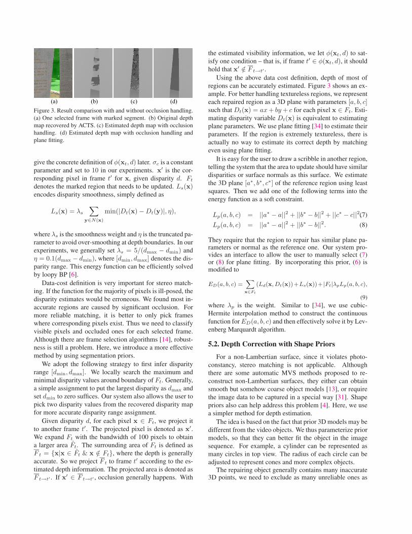
(a) (b) (c) (d)Figure 3. Result comparison with and without occlusion handling.(a) One selected frame with marked segment. (b) Original depthmap recovered by ACTS. (c) Estimated depth map with occlusionhandling. (d) Estimated depth map with occlusion handling andplane fitting.
give the concrete definition of φ(xt, d) later. σc is a constantparameter and set to 10 in our experiments. x′ is the cor-responding pixel in frame t′ for x, given disparity d. Ft
denotes the marked region that needs to be updated. Ls(x)encodes disparity smoothness, simply defined as
Ls(x) = λs
∑y∈N(x)
min(|Dt(x) − Dt(y)|, η),
where λs is the smoothness weight and η is the truncated pa-rameter to avoid over-smoothing at depth boundaries. In ourexperiments, we generally set λs = 5/(dmax − dmin) andη = 0.1(dmax − dmin), where [dmin, dmax] denotes the dis-parity range. This energy function can be efficiently solvedby loopy BP [6].
Data-cost definition is very important for stereo match-ing. If the function for the majority of pixels is ill-posed, thedisparity estimates would be erroneous. We found most in-accurate regions are caused by significant occlusion. Formore reliable matching, it is better to only pick frameswhere corresponding pixels exist. Thus we need to classifyvisible pixels and occluded ones for each selected frame.Although there are frame selection algorithms [14], robust-ness is still a problem. Here, we introduce a more effectivemethod by using segmentation priors.
We adopt the following strategy to first infer disparityrange [dmin, dmax]. We locally search the maximum andminimal disparity values around boundary of Ft. Generally,a simple assignment to put the largest disparity as dmax andset dmin to zero suffices. Our system also allows the user topick two disparity values from the recovered disparity mapfor more accurate disparity range assignment.
Given disparity d, for each pixel x ∈ Ft, we project itto another frame t′. The projected pixel is denoted as x′.We expand Ft with the bandwidth of 100 pixels to obtaina larger area Ft. The surrounding area of Ft is defined asF t = {x|x ∈ Ft & x /∈ Ft}, where the depth is generallyaccurate. So we project F t to frame t′ according to the es-timated depth information. The projected area is denoted asF t→t′ . If x′ ∈ F t→t′ , occlusion generally happens. With
the estimated visibility information, we let φ(xt, d) to sat-isfy one condition – that is, if frame t′ ∈ φ(xt, d), it shouldhold that x′ /∈ F t→t′ .
Using the above data cost definition, depth of most ofregions can be accurately estimated. Figure 3 shows an ex-ample. For better handling textureless regions, we representeach repaired region as a 3D plane with parameters [a, b, c]such that Dt(x) = ax + by + c for each pixel x ∈ Ft. Esti-mating disparity variable Dt(x) is equivalent to estimatingplane parameters. We use plane fitting [34] to estimate theirparameters. If the region is extremely textureless, there isactually no way to estimate its correct depth by matchingeven using plane fitting.
It is easy for the user to draw a scribble in another region,telling the system that the area to update should have similardisparities or surface normals as this surface. We estimatethe 3D plane [a∗, b∗, c∗] of the reference region using leastsquares. Then we add one of the following terms into theenergy function as a soft constraint.
Lp(a, b, c) = ||a∗ − a||2 + ||b∗ − b||2 + ||c∗ − c||2,(7)
Lp(a, b, c) = ||a∗ − a||2 + ||b∗ − b||2. (8)
They require that the region to repair has similar plane pa-rameters or normal as the reference one. Our system pro-vides an interface to allow the user to manually select (7)or (8) for plane fitting. By incorporating this prior, (6) ismodified to
ED(a, b, c) =∑x∈Ft
(Ld(x, Dt(x))+Ls(x))+ |Ft|λpLp(a, b, c),
(9)where λp is the weight. Similar to [34], we use cubic-Hermite interpolation method to construct the continuousfunction for ED(a, b, c) and then effectively solve it by Lev-enberg Marquardt algorithm.
5.2. Depth Correction with Shape Priors
For a non-Lambertian surface, since it violates photo-constancy, stereo matching is not applicable. Althoughthere are some automatic MVS methods proposed to re-construct non-Lambertian surfaces, they either can obtainsmooth but somehow coarse object models [13], or requirethe image data to be captured in a special way [31]. Shapepriors also can help address this problem [4]. Here, we usea simpler method for depth estimation.
The idea is based on the fact that prior 3D models may bedifferent from the video objects. We thus parameterize priormodels, so that they can better fit the object in the imagesequence. For example, a cylinder can be represented asmany circles in top view. The radius of each circle can beadjusted to represent cones and more complex objects.
The repairing object generally contains many inaccurate3D points, we need to exclude as many unreliable ones as

possible. For each pixel, we use the following criterion sim-ilar to that in [20] to measure the confidence of disparityestimate d0:
C(x) =
⎛⎝ 1
|h(d0)|∑
d∈h(d0)
e− Ld
2(x,d)−Ld2(x,d0)
σ2
⎞⎠
−1
, (10)
where σ is a constant. h(d0) = {d0 − 2Δd, d0 − Δd, d0 +Δd, d0 + 2Δd} and Δd = 0.02(dmax − dmin). C(x) islarge when the local matching cost has a sharp minimumand Ld(x, d0) is a local optimum. We select pixels onlywhen C(x) is larger than a threshold. If necessary, our sys-tem also allows the user to draw a few strokes to manuallysample reliable 3D points.
We first manually align the prior model with the selectedsparse 3D points. Then for each 3D point Xi, we find itsclosest 3D vertex Vi in the prior model. If ||Xi − Vi|| issmaller than a threshold, Xi and Vi are regarded as corre-sponding. With a set of correspondences, we further refinethe alignment by solving for an Euclidean transform [R|T ]through minimizing function
Ealign(R, T ) =∑
i
||RXi + T − Vi||2. (11)
We then transform the prior model according to [R|T ] toupdate the alignment, and re-compute the correspondence.
Due to shape difference, there could be residual devia-tion between the aligned model and video object. We useLaplacian mesh deformation [26] to further reduce it. Anexample is shown in Figure 4. Because the reconstructed3D points in the repairing area are noisy, directly takingthem as control points to deform the prior model may causeunnatural result, as shown in Figure 4(e). Considering thefact that many object parts are symmetric or rigid, we canconstrain the control points instead of directing apply themfor deformation. For the example in Figure 4, we estimatethe optimal radiuses for the circles which can find corre-sponding 3D points. Then we uniformly sample the ver-tices in the adjusted circles as control points to deform theprior model, as shown in (f). We repeat the alignment anddeformation in two passes.
After deformation, we render the depth from the de-formed model to the mask area, and inpaint depth values.The original and modified disparities for pixel x are de-noted as dx and d′x. Then we compute confidence of es-timated disparity by MVS for each pixel x in the mask as
u(x) = e− ||dx−d′
x||22σ2
p , where σp is a constant. u(x) is largewhen its original and updated disparities are close, whichwill be used in the following bundle optimization. Fig-ures 4(g) and (h) show the final depth map after bundle op-timization, where erroneous depth is corrected and accuratedepth details are faithfully preserved.
(a) (d)
(h)
(b)
(e) (g)
(c)
(f)
Figure 4. “Bottle” example. (a) One Selected frame. (b) Esti-mated depth map by ACTS. (c) Manually aligned result. (d) Re-fined alignment. (e) Direct deformation result using the spare 3Dpoints as control ones. (f) Deformation result with the circle con-straint. (g) The corrected depth map. (h) The triangular mesh of(g).
5.3. Spatio-Temporal Depth Optimization
The above steps only coarsely segment the region and es-timate its depth independently for each frame. The resultingdepth may not be temporally consistent, especially aroundregion boundaries. To improve quality, a spatio-temporaloptimization is needed.
Zhang et al. [34] proposed bundle optimization and in-corporated a geometric coherence constraint to associatemultiple frames in a statistical way. We adopt this methodbut with various modifications. In order to remove bound-ary artifacts, we dilate marked regions in all frames. Thedilated segment in frame t is denoted as F ′
t . Assuming themarked region appears in subsequence [i, j], we denote op-timized regions as {F ′
i , F′i+1, ..., F
′j}. The depth of F ′
t isoptimized by solving energy function
E′D(Dt; I) =
∑x∈F ′
t
(L′d(x,Dt(x)) + Ls(x)), (12)
where L′d(x,Dt(x)) is the data cost combing both color and
geometric coherence constraints. It is defined as
L′d(x, d) = 1 − 1
|φ(x, d)|∑
t′∈φ(x,d)
σc(x) · pv(x, d)
σc(x) + ||It(x) − It′(x′)|| , (13)
where σc(x) is an adaptive parameter, which will be intro-duced in Section 5.4. pv(·) is the geometric coherence con-straint as
pv(x,Dt(x)) =σ2
d
σ2d + ||Pt′→t(Dt′(x′)) − Dt(x)||2 .
(14)x′ is the projected point in frame t′. Pt′→t(Dt′(x′)) de-notes the transformed disparity value according to the cam-era parameters between frames t and t′. The transformeddisparity is denoted as Pt′→t(Dt′(x′)). Please refer to thesupplementary document for more details. The geometriccoherence constraint requires that Pt′→t(Dt′(x′)) equals to

(a) (b) (c)
Figure 5. “Stela” example. (a) One Selected frame. (b) The es-timated depth map by ACTS. (c) The refined depth map by oursystem.
Dt(x). Different from the method of [34], our geometriccoherence term is defined in the disparity space instead ofimage space. For each F ′
t , we fix the disparities of all otherframes and optimize the disparity in F ′
t by minimizing theenergy function defined in (12).
5.4. Adaptive Parameter Tuning
Here, we introduce an adaptive parameter tuning schemeto further optimize our system. For marked region F ′
t , wemeasure the temporal photo-consistency error εc and dis-parity consistency error εd as
εc =1
|F ′t |
∑x∈F ′
t
√ ∑t′∈φ(x,t)
||It(x) − It′(x′)||2/|φ(x, t)|,
εd =1
|F ′t |
∑x∈F ′
t
√ ∑t′∈φ(x,t)
|Pt′→t(Dt′(x′)) − Dt(x)|2/|φ(x, t)|.
In the first-pass of spatio-temporal optimization, we gen-erally set σd = max{1, (εc/K)2} · max{0.02(dmax −dmin), εd}, where K is a constant parameter. The intuitionis that if εc is small, the estimated disparities are generallygood except minor temporal noise exists. In this case, σd
should be close to the standard deviation of disparity to sup-press temporal noise. Contrarily, if εc is large, the initial-ized depth must significantly deviate from the ground truth,so σd is set to a larger value to let the photo-consistencyconstraint dominate the data term. After the first-pass opti-mization, we adjust σd = 0.8εd. Along the spatio-temporaloptimization, both εc and εd become smaller and smaller initerations for quick convergence.
The above strategy generally works well. However, ifF ′
t is a Non-Lambertian surface that violates the photo-consistency constraint, this scheme could be inappropriate.If this happens, we can set σc to a large value to weakenthe photo-consistency constraint. Especially, if the depth iscorrected with shape priors, we can obtain the confidence oforiginal disparities. So we can adjust σc for each pixel byσc(x) = 5/u(x). If u(x) is small, we weaken the photo-consistency constraint for pixel x. σd is generally set tomin{0.02(dmax−dmin),max{0.001(dmax−dmin), 0.8εd}}in our experiments.
6. Experimental Results
We experiment with different challenging video se-quences. Table 1 lists the statistics of the testing sequences.
Seq. Frames Repaired Running Time (min.)Areas Masking IDC STO
Rock 115 9 ∼10 ∼7 ∼12Stela 143 8 ∼10 ∼9 ∼13Bottle 100 2 ∼7 ∼5 ∼8
Car 121 4 ∼15 ∼7 ∼12Indoor 141 14 ∼15 ∼16 ∼19
KITTI Seq000 21 5 ∼4 ∼4 ∼2KITTI Seq070 21 8 ∼7 ∼6 ∼2KITTI Seq101 21 8 ∼5 ∼5 ∼2KITTI Seq107 21 6 ∼4 ∼5 ∼2KITTI Seq186 21 13 ∼8 ∼7 ∼3
Table 1. Running time. IDC denotes initial depth correction, andSTO denotes spatio-temporal optimization.
Figure 6. Area masking for “Indoor” example. Top: three editedconsecutive key frames (i.e. frames 50, 74 and 98). Yellow strokesdenote foreground pixels and blue strokes denote background pix-els. Bottom: the segmented region. For masking the black screen,the user only needs to edit one key frame about every 25 frameson average.
The running times are measured on a desktop PC with In-tel Xeon E3 3.30GHz (4 cores) CPU, 8GB memory, andNvidia GeForce GTX 560SE GPU. For a sequence with 100frames, our system generally takes only 1 ∼ 3 minutes toproduce the mask of one area to repair. This speed dependson the repaired area size and appearance/structure complex-ity. User interaction is only drawing a few strokes. Drawingeach stroke generally requires 1 ∼ 2 seconds. For Indoorexample with 141 frames, we draw about 150 strokes in to-tal for 14 repaired areas (i.e. 11 strokes for each repairedarea on average). Figure 6 shows some edited frames withdrawn strokes for this example. Pure interaction time isless than 5 minutes. Depth correction is almost automaticand very efficient. With GPU acceleration, it takes about2 seconds to optimize 320 × 240 pixels per frame exclud-ing IO time, so that the user can receive instant responsefrom the system. Our system is rather efficient comparedto other semi-automatic methods. For instance, the methodproposed in [33] takes about 5-10 minutes to refine eachkey-frame disparity map, and 10-20 seconds per-frame tocompute disparity. To generate similar quality results toours, this method requires more key frames. So the inter-action time is much longer.
Figure 5 shows a challenging outdoor example, which
(a) (b)
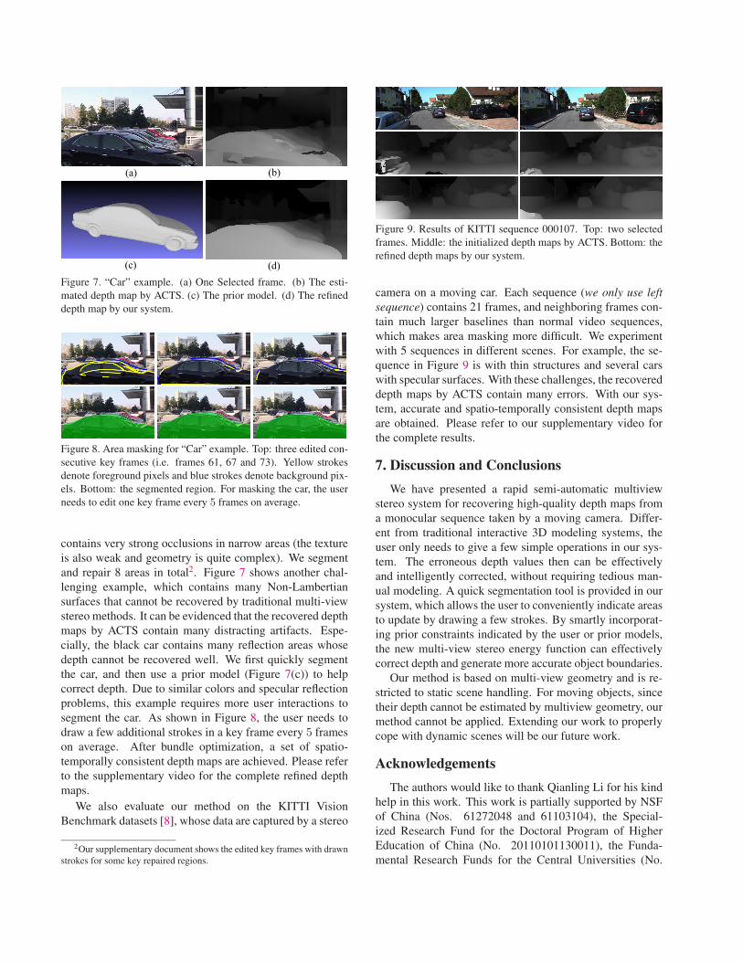
(c) (d)Figure 7. “Car” example. (a) One Selected frame. (b) The esti-mated depth map by ACTS. (c) The prior model. (d) The refineddepth map by our system.
Figure 8. Area masking for “Car” example. Top: three edited con-secutive key frames (i.e. frames 61, 67 and 73). Yellow strokesdenote foreground pixels and blue strokes denote background pix-els. Bottom: the segmented region. For masking the car, the userneeds to edit one key frame every 5 frames on average.
contains very strong occlusions in narrow areas (the textureis also weak and geometry is quite complex). We segmentand repair 8 areas in total2. Figure 7 shows another chal-lenging example, which contains many Non-Lambertiansurfaces that cannot be recovered by traditional multi-viewstereo methods. It can be evidenced that the recovered depthmaps by ACTS contain many distracting artifacts. Espe-cially, the black car contains many reflection areas whosedepth cannot be recovered well. We first quickly segmentthe car, and then use a prior model (Figure 7(c)) to helpcorrect depth. Due to similar colors and specular reflectionproblems, this example requires more user interactions tosegment the car. As shown in Figure 8, the user needs todraw a few additional strokes in a key frame every 5 frameson average. After bundle optimization, a set of spatio-temporally consistent depth maps are achieved. Please referto the supplementary video for the complete refined depthmaps.
We also evaluate our method on the KITTI VisionBenchmark datasets [8], whose data are captured by a stereo
2Our supplementary document shows the edited key frames with drawnstrokes for some key repaired regions.
Figure 9. Results of KITTI sequence 000107. Top: two selectedframes. Middle: the initialized depth maps by ACTS. Bottom: therefined depth maps by our system.
camera on a moving car. Each sequence (we only use leftsequence) contains 21 frames, and neighboring frames con-tain much larger baselines than normal video sequences,which makes area masking more difficult. We experimentwith 5 sequences in different scenes. For example, the se-quence in Figure 9 is with thin structures and several carswith specular surfaces. With these challenges, the recovereddepth maps by ACTS contain many errors. With our sys-tem, accurate and spatio-temporally consistent depth mapsare obtained. Please refer to our supplementary video forthe complete results.
7. Discussion and Conclusions
We have presented a rapid semi-automatic multiviewstereo system for recovering high-quality depth maps froma monocular sequence taken by a moving camera. Differ-ent from traditional interactive 3D modeling systems, theuser only needs to give a few simple operations in our sys-tem. The erroneous depth values then can be effectivelyand intelligently corrected, without requiring tedious man-ual modeling. A quick segmentation tool is provided in oursystem, which allows the user to conveniently indicate areasto update by drawing a few strokes. By smartly incorporat-ing prior constraints indicated by the user or prior models,the new multi-view stereo energy function can effectivelycorrect depth and generate more accurate object boundaries.
Our method is based on multi-view geometry and is re-stricted to static scene handling. For moving objects, sincetheir depth cannot be estimated by multiview geometry, ourmethod cannot be applied. Extending our work to properlycope with dynamic scenes will be our future work.
Acknowledgements
The authors would like to thank Qianling Li for his kindhelp in this work. This work is partially supported by NSFof China (Nos. 61272048 and 61103104), the Special-ized Research Fund for the Doctoral Program of HigherEducation of China (No. 20110101130011), the Funda-mental Research Funds for the Central Universities (No.
2014FZA5017), a Foundation for the Author of NationalExcellent Doctoral Dissertation of PR China (No. 201245),and a grant from the Research Grants Council of the HongKong Special Administrative Region (Project No. 413113).
References
[1] ACTS 2.0: Automatic Camera Tracking System. http://www.zjucvg.net/acts/acts.html, 2014.
[2] A. Agarwala, A. Hertzmann, D. Salesin, and S. M. Seitz.Keyframe-based tracking for rotoscoping and animation.ACM Trans. Graph., 23(3):584–591, 2004.
[3] X. Bai, J. Wang, D. Simons, and G. Sapiro. Video snapcut:robust video object cutout using localized classifiers. ACMTrans. Graph., 28(3), 2009.
[4] S. Y.-Z. Bao, M. Chandraker, Y. Lin, and S. Savarese. Denseobject reconstruction with semantic priors. In CVPR, pages1264–1271, 2013.
[5] Y. Boykov, O. Veksler, and R. Zabih. Fast approximate en-ergy minimization via graph cuts. IEEE Trans. Pattern Anal.Mach. Intell., 23(11):1222–1239, 2001.
[6] P. F. Felzenszwalb and D. P. Huttenlocher. Efficient beliefpropagation for early vision. International Journal of Com-puter Vision, 70(1):41–54, 2006.
[7] M. A. Fischler and R. C. Bolles. Random sample consen-sus: A paradigm for model fitting with applications to im-age analysis and automated cartography. Commun. ACM,24(6):381–395, 1981.
[8] A. Geiger, P. Lenz, C. Stiller, and R. Urtasun. Visionmeets robotics: The KITTI dataset. International Journalof Robotics Research (IJRR), 2013.
[9] M. Guttmann, L. Wolf, and D. Cohen-or. Semi-automaticstereo extraction from video footage. In ICCV, 2009.
[10] M. Habbecke and L. Kobbelt. An intuitive interface for inter-active high quality image-based modeling. Comput. Graph.Forum, 28(7):1765–1772, 2009.
[11] P. Harman, J. Flack, S. Fox, and M. Dowley. Rapid 2D to 3Dconversion. In Proc. SPIE 4660, Stereoscopic Displays andVirtual Reality Systems IX, pages 78–86, 2002.
[12] R. I. Hartley and A. Zisserman. Multiple View Geometryin Computer Vision. Cambridge University Press, ISBN:0521540518, second edition, 2004.
[13] H. Jin, S. Soatto, and A. J. Yezzi. Multi-view stereo recon-struction of dense shape and complex appearance. Interna-tional Journal of Computer Vision, 63(3):175–189, 2005.
[14] S. B. Kang and R. Szeliski. Extracting view-dependent depthmaps from a collection of images. International Journal ofComputer Vision, 58(2):139–163, 2004.
[15] J. J. Koenderink, A. J. van Doorn, A. M. L. Kappers, andJ. T. Todd. Ambiguity and the ‘mental eye’ in pictorial relief.Perception, 30(4):431 C 448, 2000.
[16] Z. Li, X. Xie, and X. Liu. An efficient 2D to 3D video con-version method based on skeleton line tracking. In 3DTVConference: The True Vision - Capture, Transmission andDisplay of 3D Video, pages 1 – 4, 2009.
[17] M. Liao, J. Gao, R. Yang, and M. Gong. Video stereoliza-tion: Combining motion analysis with user interaction. IEEETrans. Vis. Comput. Graph., 18(7):1079–1088, 2012.
[18] J. Liu, J. Sun, and H.-Y. Shum. Paint selection. ACM Trans.Graph., 28(3), 2009.
[19] B. D. Lucas and T. Kanade. An iterative image registra-tion technique with an application to stereo vision. In IJCAI,pages 674–679, 1981.
[20] P. Merrell, A. Akbarzadeh, L. Wang, P. Mordohai, J.-M.Frahm, R. Yang, D. Nister, and M. Pollefeys. Real-timevisibility-based fusion of depth maps. In ICCV, pages 1–8,2007.
[21] B. L. Price, B. S. Morse, and S. Cohen. Livecut: Learning-based interactive video segmentation by evaluation of multi-ple propagated cues. In ICCV, pages 779–786, 2009.
[22] C. Rother, V. Kolmogorov, and A. Blake. “Grabcut”: inter-active foreground extraction using iterated graph cuts. ACMTrans. Graph., 23(3):309–314, 2004.
[23] S. M. Seitz, B. Curless, J. Diebel, D. Scharstein, andR. Szeliski. A comparison and evaluation of multi-viewstereo reconstruction algorithms. In CVPR (1), pages 519–528, 2006.
[24] J. Shi and C. Tomasi. Good features to track. In CVPR, pages593–600, 1994.
[25] S. N. Sinha, D. Steedly, R. Szeliski, M. Agrawala, andM. Pollefeys. Interactive 3D architectural modeling fromunordered photo collections. ACM Trans. Graph., 27(5):159,2008.
[26] O. Sorkine, D. Cohen-Or, Y. Lipman, M. Alexa, C. Rossl,and H.-P. Seidel. Laplacian surface editing. In Symposiumon Geometry Processing, pages 175–184, 2004.
[27] P. Tan, G. Zeng, J. Wang, S. B. Kang, and L. Quan. Image-based tree modeling. ACM Trans. Graph., 26(3):87, 2007.
[28] A. van den Hengel, A. R. Dick, T. Thormahlen, B. Ward, andP. H. S. Torr. Videotrace: rapid interactive scene modellingfrom video. ACM Trans. Graph., 26(3):86, 2007.
[29] H.-M. Wang, C.-H. Huang, and J.-F. Yang. Depth maps in-terpolation from existing pairs of keyframes and depth mapsfor 3d video generation. In IEEE International Symposiumon Circuits and Systems (ISCAS), pages 3248 – 3251, 2010.
[30] J. Wang, P. Bhat, A. Colburn, M. Agrawala, and M. F. Cohen.Interactive video cutout. ACM Trans. Graph., 24(3):585–594, 2005.
[31] S. Wanner and B. Goldluecke. Reconstructing reflective andtransparent surfaces from epipolar plane images. In Pat-tern Recognition - 35th German Conference, GCPR 2013,Saarbrucken, Germany, September 3-6, 2013. Proceedings,pages 1–10, 2013.
[32] J. Xiao, T. Fang, P. Tan, P. Zhao, E. Ofek, and L. Quan.Image-based facade modeling. ACM Trans. Graph.,27(5):161, 2008.
[33] C. Zhang, B. L. Price, S. Cohen, and R. Yang. High-qualitystereo video matching via user interaction and space-timepropagation. In 3DV, pages 71–78, 2013.
[34] G. Zhang, J. Jia, T.-T. Wong, and H. Bao. Consistent depthmaps recovery from a video sequence. IEEE Trans. PatternAnal. Mach. Intell., 31(6):974–988, 2009.
[35] F. Zhong, X. Qin, Q. Peng, and X. Meng. Discontinuity-aware video object cutout. ACM Trans. Graph., 31(6):175,2012.


![MVSNet: Depth Inference for Unstructured Multi-view Stereo · 2018. 8. 28. · MVSNet: Depth Inference for UnstructuredMulti-view Stereo Yao Yao1⋆[0000−0001−9866−4291], Zixin](https://static.fdocuments.net/doc/165x107/60f6aaa4f14d9349a7590698/mvsnet-depth-inference-for-unstructured-multi-view-stereo-2018-8-28-mvsnet.jpg)