DULCODOS Pool Professional - ProMinent
60
DULCODOS Pool Professional Assembly and operating instructions A0988 EN Original Operating Instructions (2006/42/EC) Part no. 984156 Version: BA DD 035 06/15 EN Please carefully read these operating instructions before use. · Do not discard. The operator shall be liable for any damage caused by installation or operating errors. The latest version of the operating instructions are available on our homepage.
Transcript of DULCODOS Pool Professional - ProMinent
DULCODOS Pool ProfessionalAssembly and operating instructions
A0988
EN
Original Operating Instructions (2006/42/EC)Part no. 984156 Version: BA DD 035 06/15 EN
Please carefully read these operating instructions before use. · Do not discard.The operator shall be liable for any damage caused by installation or operating errors.
The latest version of the operating instructions are available on our homepage.
In order to make it easier to read, this document uses the male form ingrammatical structures but with an implied neutral sense. It is aimedequally at both men and women. We kindly ask female readers for theirunderstanding in this simplification of the text.
Please read the supplementary information in its entirety.
Information
This provides important information relating to the cor‐rect operation of the unit or is intended to make yourwork easier.
Safety Information
The safety information includes detailed descriptions of the hazardous sit‐uation, see Ä Chapter 3.2 ‘Explanation of the safety information’on page 10The following symbols are used to highlight instructions, links, lists, resultsand other elements in this document:
Tab. 1: More symbolsSymbol Description
Action, step by step
⇨ Outcome of an action
Links to elements or sections of these instructions or other applicable documents
n List without set order
[Button] Display element (e.g. indicators)
Operating element (e.g. button, switch)
‘Display /GUI’ Screen elements (e.g. buttons, assignment of function keys)
CODE Presentation of software elements and/or texts
General non-discriminatory approach
Supplementary information
Supplemental directives
2

Table of contents1 Identity code.................................................................................... 4
2 About This Product.......................................................................... 72.1 Overview of Equipment........................................................... 7
3 Safety and Responsibility.............................................................. 103.1 Users' qualifications.............................................................. 103.2 Explanation of the safety information.................................... 103.3 General Safety Information................................................... 123.4 Intended Use......................................................................... 13
4 Device overview and operating elements...................................... 14
5 Storage and transport.................................................................... 16
6 Assembly....................................................................................... 176.1 Wall mounting....................................................................... 176.2 Fit the antikink device for the bleed line................................ 186.3 Hydraulic Installation............................................................. 196.3.1 Metering system................................................................. 206.3.2 Sensors.............................................................................. 236.4 Electrical Installation............................................................. 246.4.1 Connect power supply........................................................ 256.4.2 Electrical installation of the sensors................................... 256.4.3 Cable Cross-Sections and Cable End Sleeves.................. 25
7 Start Up......................................................................................... 267.1 Adjust the flow sensor switching point.................................. 277.2 Priming and bleeding (with an alpha or Beta pump)............. 287.3 Calibration............................................................................. 287.3.1 Chlorine calibration............................................................ 297.3.2 ORP calibration.................................................................. 397.3.3 calibration pH..................................................................... 40
8 Maintenance.................................................................................. 448.1 Maintenance work................................................................. 448.2 Replacing the chemical storage tanks.................................. 468.3 Troubleshooting.................................................................... 468.4 Disposal of Used Parts.......................................................... 47
9 Drawings, Drilling and External Dimensions of the DUL‐CODOS®........................................................................................ 48
10 Technical Data............................................................................... 51
11 Spare Parts and Accessories........................................................ 52
12 EC Declaration of Conformity........................................................ 54
13 Index.............................................................................................. 56
Table of contents
3
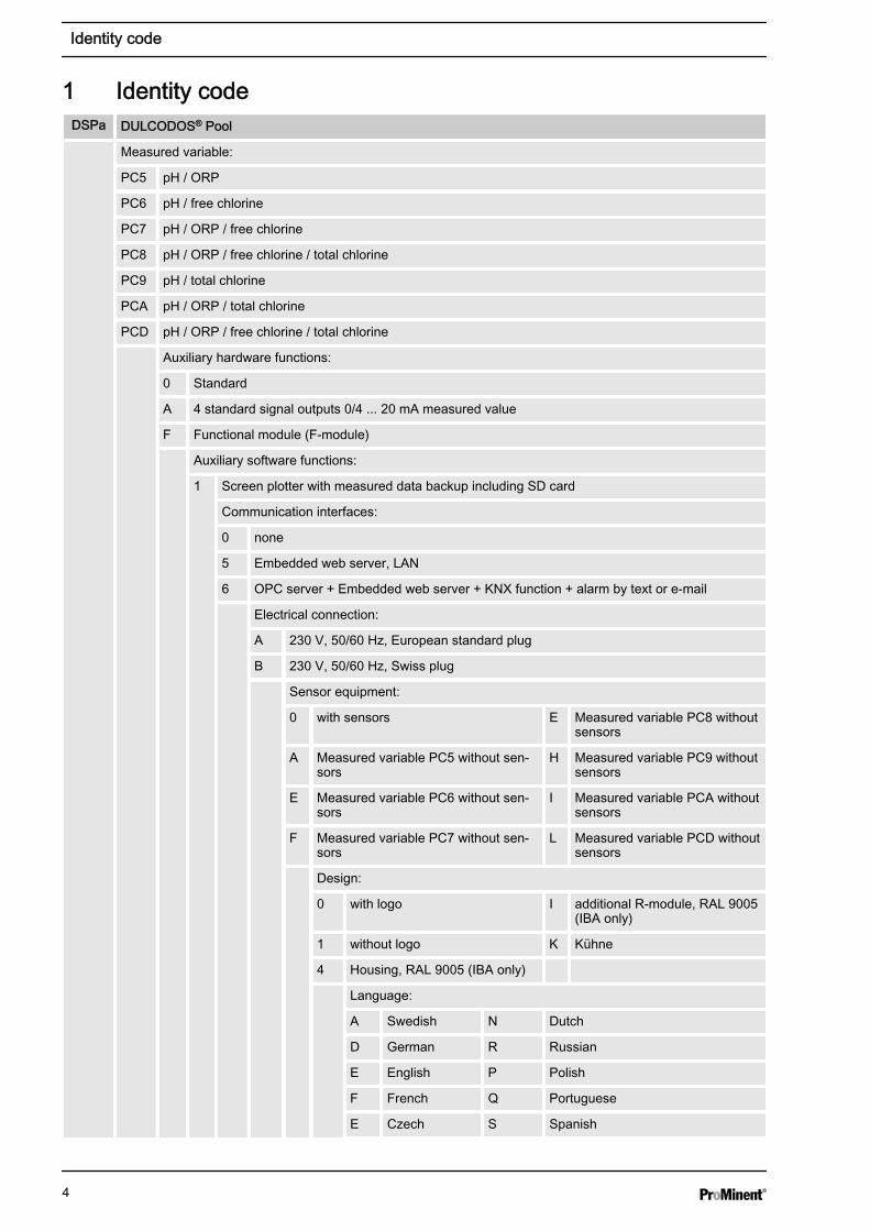
1 Identity codeDSPa DULCODOS® Pool
Measured variable:
PC5 pH / ORP
PC6 pH / free chlorine
PC7 pH / ORP / free chlorine
PC8 pH / ORP / free chlorine / total chlorine
PC9 pH / total chlorine
PCA pH / ORP / total chlorine
PCD pH / ORP / free chlorine / total chlorine
Auxiliary hardware functions:
0 Standard
A 4 standard signal outputs 0/4 ... 20 mA measured value
F Functional module (F-module)
Auxiliary software functions:
1 Screen plotter with measured data backup including SD card
Communication interfaces:
0 none
5 Embedded web server, LAN
6 OPC server + Embedded web server + KNX function + alarm by text or e-mail
Electrical connection:
A 230 V, 50/60 Hz, European standard plug
B 230 V, 50/60 Hz, Swiss plug
Sensor equipment:
0 with sensors E Measured variable PC8 withoutsensors
A Measured variable PC5 without sen‐sors
H Measured variable PC9 withoutsensors
E Measured variable PC6 without sen‐sors
I Measured variable PCA withoutsensors
F Measured variable PC7 without sen‐sors
L Measured variable PCD withoutsensors
Design:
0 with logo I additional R-module, RAL 9005(IBA only)
1 without logo K Kühne
4 Housing, RAL 9005 (IBA only)
Language:
A Swedish N Dutch
D German R Russian
E English P Polish
F French Q Portuguese
E Czech S Spanish
Identity code
4
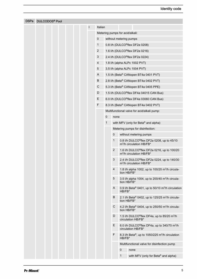
DSPa DULCODOS® Pool
I Italian
Metering pumps for acid/alkali:
0 without metering pumps
1 0.8 l/h (DULCO®flex DF2a 0208)
2 1.6 l/h (DULCO®flex DF2a 0216)
3 2.4 l/h (DULCO®flex DF2a 0224)
4 1.8 l/h (alpha ALPc 1002 PVT)
5 3.5 l/h (alpha ALPc 1004 PVT)
A 1.5 l/h (Beta® CANopen BT4a 0401 PVT)
B 2.8 l/h (Beta® CANopen BT4a 0402 PVT)
C 5.3 l/h (Beta® CANopen BT4a 0405 PPE)
D 1.5 l/h (DULCO®flex DF4a 04015 CAN Bus)
E 6.0 l/h (DULCO®flex DF4a 03060 CAN Bus)
F 8.3 l/h (Beta® CANopen BT4a 0402 PVT)
Multifunctional valve for acid/alkali pump:
0 none
1 with MFV (only for Beta® and alpha)
Metering pumps for disinfection:
0 without metering pumps
1 0.8 l/h DULCO®flex DF2a 0208, up to 45/10m3/h circulation HB/FB*
2 1.6 l/h DULCO®flex DF2a 0216, up to 100/20m3/h circulation HB/FB*
3 2.4 l/h DULCO®flex DF2a 0224, up to 140/30m3/h circulation HB/FB*
4 1.8 l/h alpha 1002, up to 100/20 m3/h circula‐tion HB/FB*
5 3.5 l/h alpha 1004, up to 200/40 m3/h circula‐tion HB/FB*
A 0.9 l/h Beta® 0401, up to 50/10 m3/h circulationHB/FB*
B 2.1 l/h Beta® 0402, up to 125/25 m3/h circula‐tion HB/FB*
C 4.2 l/h Beta® 0404, up to 250/50 m3/h circula‐tion HB/FB*
D 1.5 l/h DULCO®flex DF4a, up to 85/20 m3/hcirculation HB/FB*
E 6.0 l/h DULCO®flex DF4a, up to 340/70 m3/hcirculation HB/FB*
F 8.3 l/h Beta®, up to 1050/225 m3/h circulationHB/FB*
Multifunctional valve for disinfection pump
0 none
1 with MFV (only for Beta® and alpha)
Identity code
5

DSPa DULCODOS® Pool
Assembly
0 supplied loose without mountingplate
1 mounted on a base plate
C Base plate with flocculant pumpDF4a
Certification
0 with CE certification
* Calculated for 12% sodium-calcium hypochlorite. HB=indoor pool/ FB=outdoor pool.
Identity code
6
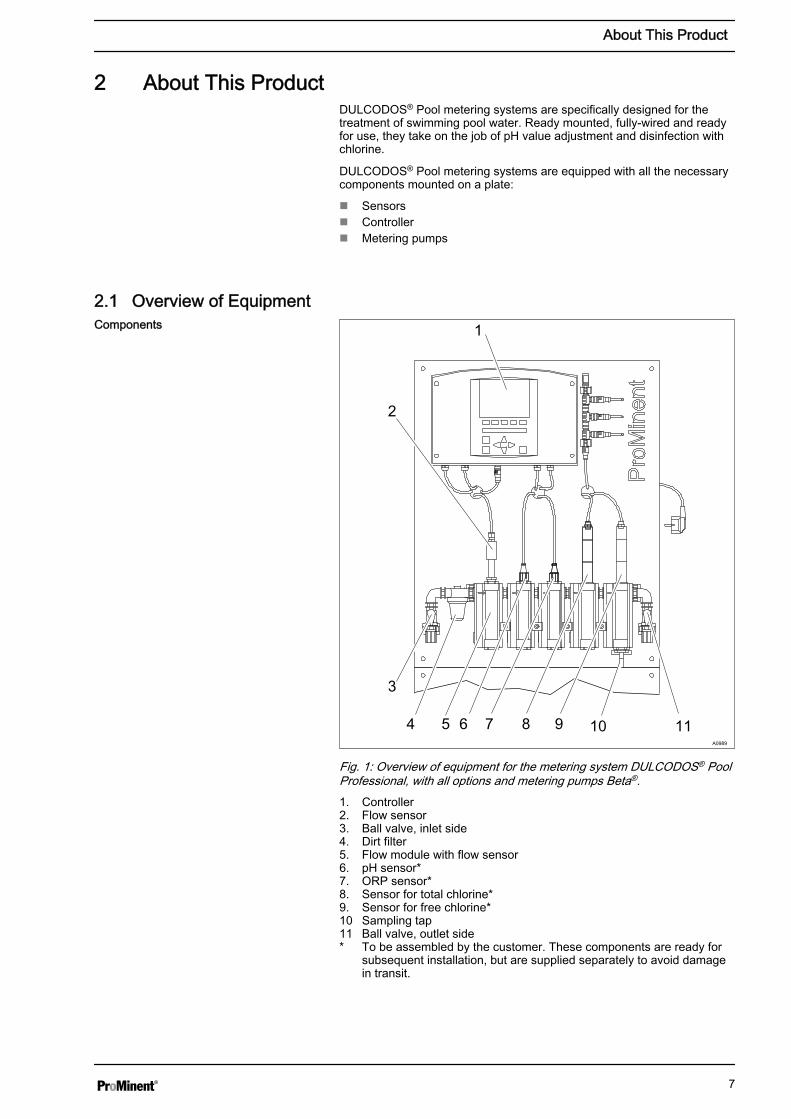
2 About This ProductDULCODOS® Pool metering systems are specifically designed for thetreatment of swimming pool water. Ready mounted, fully-wired and readyfor use, they take on the job of pH value adjustment and disinfection withchlorine.
DULCODOS® Pool metering systems are equipped with all the necessarycomponents mounted on a plate:
n Sensorsn Controllern Metering pumps
2.1 Overview of Equipment1
2
3
4 5 6 7 8 9 10 11A0989
Fig. 1: Overview of equipment for the metering system DULCODOS® PoolProfessional, with all options and metering pumps Beta®.1. Controller2. Flow sensor3. Ball valve, inlet side4. Dirt filter5. Flow module with flow sensor6. pH sensor*7. ORP sensor*8. Sensor for total chlorine*9. Sensor for free chlorine*10 Sampling tap11 Ball valve, outlet side* To be assembled by the customer. These components are ready for
subsequent installation, but are supplied separately to avoid damagein transit.
Components
About This Product
7
12a
13a
14a
15a
12b
13b
14b
15b
A0990
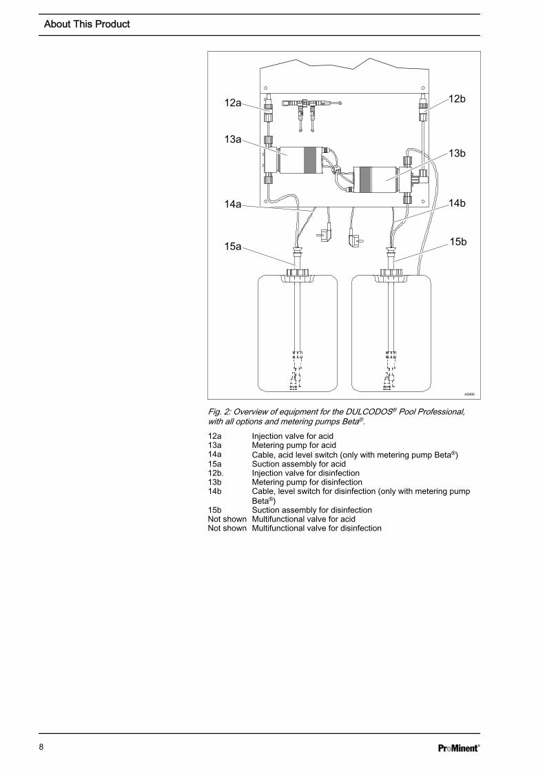
Fig. 2: Overview of equipment for the DULCODOS® Pool Professional,with all options and metering pumps Beta®.12a Injection valve for acid13a Metering pump for acid14a Cable, acid level switch (only with metering pump Beta®)15a Suction assembly for acid12b. Injection valve for disinfection13b Metering pump for disinfection14b Cable, level switch for disinfection (only with metering pump
Beta®)15b Suction assembly for disinfectionNot shown Multifunctional valve for acidNot shown Multifunctional valve for disinfection
About This Product
8
1
2
3a
3b
4
A0991
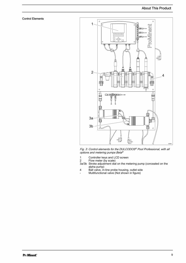
Fig. 3: Control elements for the DULCODOS® Pool Professional, with alloptions and metering pumps Beta®
1 Controller keys and LCD screen2 Flow meter (by scale)3a/3b Stroke adjustment dial on the metering pump (concealed on the
alpha pump)4 Ball valve, in-line probe housing, outlet side- Multifunctional valve (Not shown in figure)
Control Elements
About This Product
9
3 Safety and Responsibility3.1 Users' qualifications
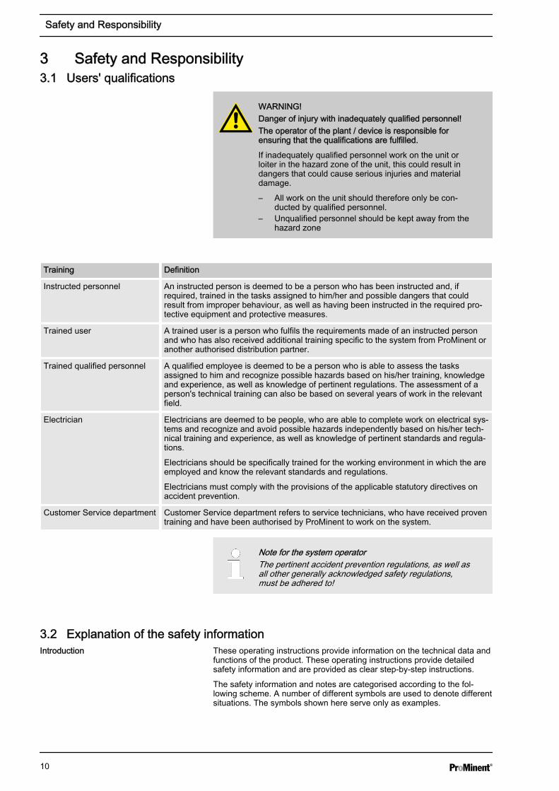
WARNING!Danger of injury with inadequately qualified personnel!The operator of the plant / device is responsible forensuring that the qualifications are fulfilled.
If inadequately qualified personnel work on the unit orloiter in the hazard zone of the unit, this could result indangers that could cause serious injuries and materialdamage.
– All work on the unit should therefore only be con‐ducted by qualified personnel.
– Unqualified personnel should be kept away from thehazard zone
Training Definition
Instructed personnel An instructed person is deemed to be a person who has been instructed and, ifrequired, trained in the tasks assigned to him/her and possible dangers that couldresult from improper behaviour, as well as having been instructed in the required pro‐tective equipment and protective measures.
Trained user A trained user is a person who fulfils the requirements made of an instructed personand who has also received additional training specific to the system from ProMinent oranother authorised distribution partner.
Trained qualified personnel A qualified employee is deemed to be a person who is able to assess the tasksassigned to him and recognize possible hazards based on his/her training, knowledgeand experience, as well as knowledge of pertinent regulations. The assessment of aperson's technical training can also be based on several years of work in the relevantfield.
Electrician Electricians are deemed to be people, who are able to complete work on electrical sys‐tems and recognize and avoid possible hazards independently based on his/her tech‐nical training and experience, as well as knowledge of pertinent standards and regula‐tions.
Electricians should be specifically trained for the working environment in which the areemployed and know the relevant standards and regulations.
Electricians must comply with the provisions of the applicable statutory directives onaccident prevention.
Customer Service department Customer Service department refers to service technicians, who have received proventraining and have been authorised by ProMinent to work on the system.
Note for the system operatorThe pertinent accident prevention regulations, as well asall other generally acknowledged safety regulations,must be adhered to!
3.2 Explanation of the safety informationThese operating instructions provide information on the technical data andfunctions of the product. These operating instructions provide detailedsafety information and are provided as clear step-by-step instructions.
The safety information and notes are categorised according to the fol‐lowing scheme. A number of different symbols are used to denote differentsituations. The symbols shown here serve only as examples.
Introduction
Safety and Responsibility
10
DANGER!Nature and source of the dangerConsequence: Fatal or very serious injuries.
Measure to be taken to avoid this danger
Danger!
– Denotes an immediate threatening danger. If this isdisregarded, it will result in fatal or very serious inju‐ries.
WARNING!Nature and source of the dangerPossible consequence: Fatal or very serious injuries.
Measure to be taken to avoid this danger
Warning!
– Denotes a possibly hazardous situation. If this is dis‐regarded, it could result in fatal or very serious inju‐ries.
CAUTION!Nature and source of the dangerPossible consequence: Slight or minor injuries, materialdamage.
Measure to be taken to avoid this danger
Caution!
– Denotes a possibly hazardous situation. If this is dis‐regarded, it could result in slight or minor injuries.May also be used as a warning about materialdamage.
NOTICE!Nature and source of the dangerDamage to the product or its surroundings
Measure to be taken to avoid this danger
Note!
– Denotes a possibly damaging situation. If this is dis‐regarded, the product or an object in its vicinitycould be damaged.
Type of informationHints on use and additional informationSource of the information, additional measuresInformation!– Denotes hints on use and other useful information. It
does not indicate a hazardous or damaging situa‐tion.
Safety and Responsibility
11
3.3 General Safety Information
WARNING!Danger from hazardous substances!Possible consequence: Fatal or very serious injuries.
Please ensure when handling hazardous substancesthat you have read the latest safety data sheets providedby the manufacture of the hazardous substance. Theactions required are described in the safety data sheet.Check the safety data sheet regularly and replace, ifnecessary, as the hazard potential of a substance canbe re-evaluated at any time based on new findings.
The system operator is responsible for ensuring thatthese safety data sheets are available and that they arekept up to date, as well as for producing an associatedhazard assessment for the workstations affected.
WARNING!Live parts!Possible consequence: Fatal or very serious injuries
– Measure: Disconnect the mains power supply priorto opening the housing
– De-energise damaged, defective units or units thathave been tampered with by disconnecting themains plug
WARNING!Unauthorised access!Possible consequence: Fatal or very serious injuries.
– Measure: Ensure that there can be no unauthorisedaccess to the unit
WARNING!Operating faults!Possible consequence: Fatal or very serious injuries.
– Ensure that the unit is only operated by adequatelyqualified and technically expert personnel
– Please also observe the operating instructions forcontrollers and fittings and any other componentgroups, such as sensors, sample water pumps ...
– The operator is responsible for ensuring that per‐sonnel are qualified
CAUTION!Electronic malfunctionsPossible consequence: Material damage right through toirreparable damage to the unit
– Do not lay the mains connection cable and datacable together with cables that are prone to interfer‐ence
– Measure: Take appropriate interference suppressionmeasures
Safety and Responsibility
12
CAUTION!Warning of feed chemical spraying aroundSpraying feed chemical caused by a leak.
Possible consequence: Injuries caused by chemicals.
– Regularly check the system for leaks.– Ensure that the system with all components can be
de-energised from outside the danger zone byappropriate measures (e.g. emergency stop switchetc.).
NOTICE!Correct sensor operation / Run-in periodDamage to the product or its surroundings
– Correct measuring and metering is only possible ifthe sensor is working perfectly
– It is imperative that the run-in periods for the sen‐sors are adhered to
– Allow for run-in periods when planning commis‐sioning
– It may take a whole working day to run in the sensor– Please read the operating instructions for the sensor
NOTICE!Correct sensor operationDamage to the product or its surroundings.
– Correct measuring and metering is only possible ifthe sensor is working perfectly
– Check and calibrate the sensor regularly
NOTICE!Compensation for control deviationsDamage to the product or its surroundings
– This controller cannot be used in control circuitswhich require rapid compensation (< 30 s)
3.4 Intended Use
Intended UseThe unit is designed to measure and regulate the pHvalue and chlorine content in swimming pools. Usuallythe integrated metering pumps are intended for meteringthe necessary chemicals. Only connect other feederassemblies, such as electrolysis systems or calciumhypochlorite systems, if these systems are intended foruse in swimming pools.Only use the unit in accordance with the technical detailsand specifications provided in these operating instruc‐tions and in the operating instructions for the individualcomponents (such as sensors, fittings, calibration instru‐ments, metering pumps etc.).All other uses or modifications are prohibited.
Safety and Responsibility
13

4 Device overview and operating elements
A0502
Fig. 4: Keys1. Enter key2. Start/Stop key3. ESC key4. Arrow keys5. Function keys, variably assigned
Keys
Device overview and operating elements
14
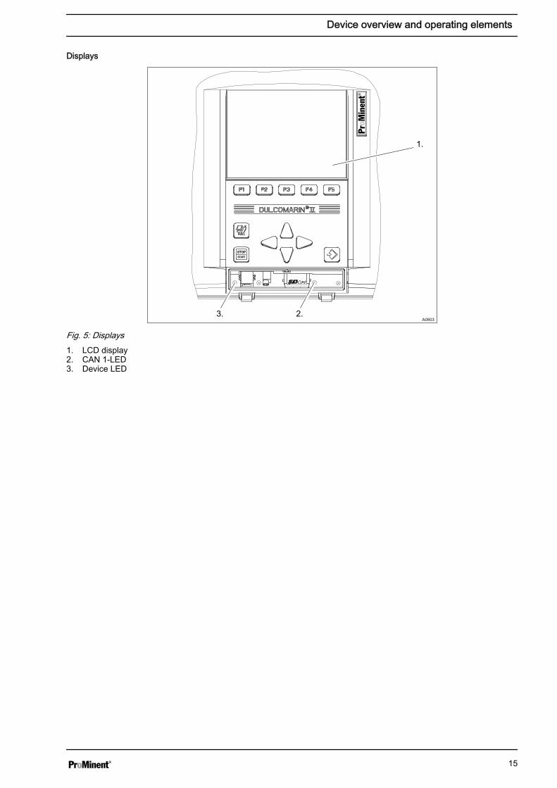
A0503
Fig. 5: Displays1. LCD display2. CAN 1-LED3. Device LED
Displays
Device overview and operating elements
15
5 Storage and transport
CAUTION!– Prior to storage or transport, the
DULCODOS® Pool metering systems must be freefrom feed chemicals and water
– Rinse out the media carrying parts, including thetubes using clean, pure water
– Transport and store the DULCODOS® Pool meteringsystems in their original packaging
– Also protect the packaged DULCODOS® Poolmetering systems against damp, exposure to chemi‐cals and mechanical effects
– Please also observe the operating instructions forcontrollers and fittings and other units, such as sen‐sors, filters, metering pumps ...
Storage temperature: 0 ... 50 °C
Air humidity: < 95% relative air humidity, non-condensing
NOTICE!If the DULCODOS® Pool metering systems are stored asan assembly with the sensors, then the storage andtransport conditions must be appropriate for the compo‐nent with the least resistance to external influences.
Ambient conditions for storage and trans‐port without sensors
Storage and transport
16

6 Assembly6.1 Wall mounting
Secure the metering system perpendicular and uprighton a wall or a stable mounting system.The metering system should be freely accessible.
Select the mounting height you require so that:
n The controller's display can be easily readn There is still space for maintenance work beneath the in-line probe
housing (100 mm)n There is still room for the chemical storage tank (600 mm)n The fluid level of the full chemical storage tanks is below the metering
pumpsn The maximum priming lift of the metering pumps is not exceeded.
10 mm
A0924
1 23 4
Fig. 6: Hanger bolt1 Rawlplug (type dependent on substrate and according to stipulations
of the rawlplug manufacturer)2 Hanger bolt3 U-washer4 Hexagon nut
Assembly
17
6.2 Fit the antikink device for the bleed line
A0965
4.
3.
2.
1.
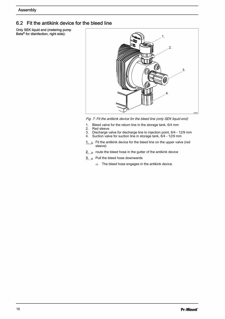
Fig. 7: Fit the antikink device for the bleed line (only SEK liquid end)1. Bleed valve for the return line in the storage tank, 6/4 mm2. Red sleeve3. Discharge valve for discharge line to injection point, 6/4 - 12/9 mm4. Suction valve for suction line in storage tank, 6/4 - 12/9 mm
1. Fit the antikink device for the bleed line on the upper valve (redsleeve)
2. route the bleed hose in the gutter of the antikink device
3. Pull the bleed hose downwards
ð The bleed hose engages in the antikink device.
Only SEK liquid end (metering pumpBeta® for disinfection, right side):
Assembly
18
6.3 Hydraulic Installation
A0993
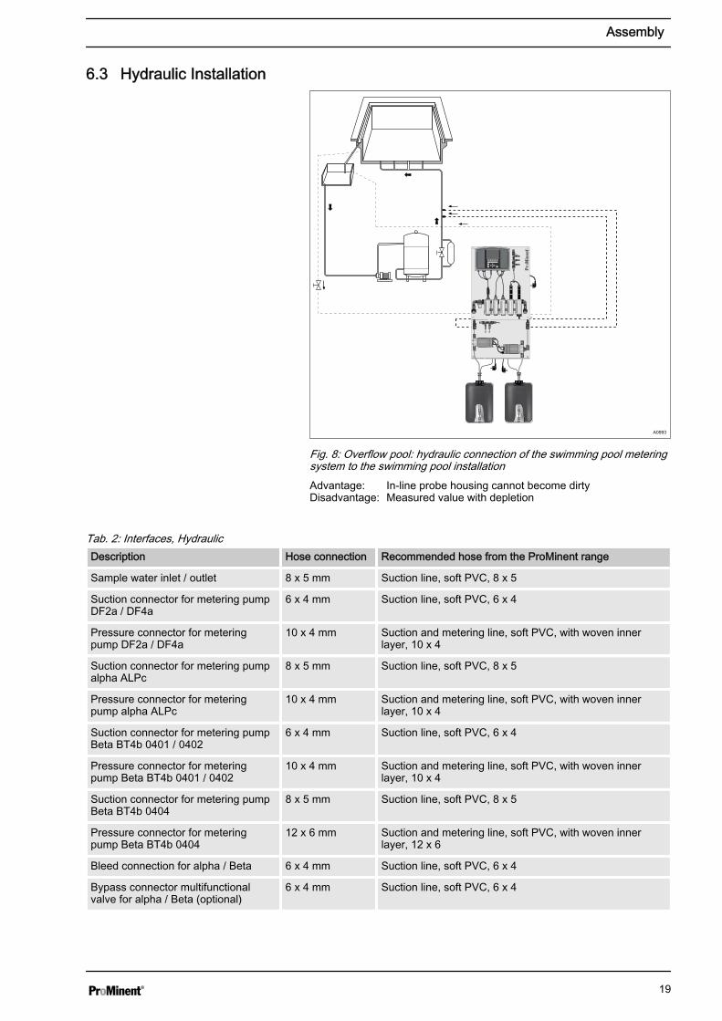
Fig. 8: Overflow pool: hydraulic connection of the swimming pool meteringsystem to the swimming pool installationAdvantage: In-line probe housing cannot become dirtyDisadvantage: Measured value with depletion
Tab. 2: Interfaces, HydraulicDescription Hose connection Recommended hose from the ProMinent range
Sample water inlet / outlet 8 x 5 mm Suction line, soft PVC, 8 x 5
Suction connector for metering pumpDF2a / DF4a
6 x 4 mm Suction line, soft PVC, 6 x 4
Pressure connector for meteringpump DF2a / DF4a
10 x 4 mm Suction and metering line, soft PVC, with woven innerlayer, 10 x 4
Suction connector for metering pumpalpha ALPc
8 x 5 mm Suction line, soft PVC, 8 x 5
Pressure connector for meteringpump alpha ALPc
10 x 4 mm Suction and metering line, soft PVC, with woven innerlayer, 10 x 4
Suction connector for metering pumpBeta BT4b 0401 / 0402
6 x 4 mm Suction line, soft PVC, 6 x 4
Pressure connector for meteringpump Beta BT4b 0401 / 0402
10 x 4 mm Suction and metering line, soft PVC, with woven innerlayer, 10 x 4
Suction connector for metering pumpBeta BT4b 0404
8 x 5 mm Suction line, soft PVC, 8 x 5
Pressure connector for meteringpump Beta BT4b 0404
12 x 6 mm Suction and metering line, soft PVC, with woven innerlayer, 12 x 6
Bleed connection for alpha / Beta 6 x 4 mm Suction line, soft PVC, 6 x 4
Bypass connector multifunctionalvalve for alpha / Beta (optional)
6 x 4 mm Suction line, soft PVC, 6 x 4
Assembly
19
6.3.1 Metering system
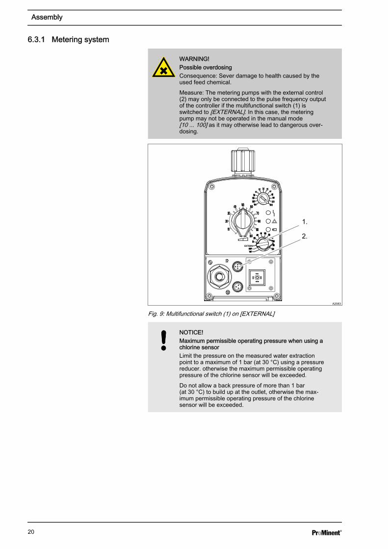
WARNING!Possible overdosingConsequence: Sever damage to health caused by theused feed chemical.
Measure: The metering pumps with the external control(2) may only be connected to the pulse frequency outputof the controller if the multifunctional switch (1) isswitched to [EXTERNAL]. In this case, the meteringpump may not be operated in the manual mode[10 ... 100] as it may otherwise lead to dangerous over‐dosing.
1.
A2083
2.
Fig. 9: Multifunctional switch (1) on [EXTERNAL]
NOTICE!Maximum permissible operating pressure when using achlorine sensorLimit the pressure on the measured water extractionpoint to a maximum of 1 bar (at 30 °C) using a pressurereducer. otherwise the maximum permissible operatingpressure of the chlorine sensor will be exceeded.
Do not allow a back pressure of more than 1 bar(at 30 °C) to build up at the outlet, otherwise the max‐imum permissible operating pressure of the chlorinesensor will be exceeded.
Assembly
20
NOTICE!Multifunctional valve: Point of injection with non-returnvalveIf you use a mutifunctional valve, then a non-return valvemust be fitted at the point of injection (integrated in thesupplied injection valve). Otherwise, when the multifunc‐tional valve is activated, the swimming pool water mayflow back via the bypass line.
1. With flow sensor: Push the flow sensor into the in-line probehousing and tighten the reducing nipple and the mounting clip
2. Route the sample water feed via a ball valve from the filter circuit orthe sample water pump to the in-line probe housing, see figuresabove
3. Route the sample water feed via a ball valve from the filtration circuitto the in-line probe housing or via a free outlet into the surge watertank, see figures above
4. Install a 1/2" straight union on the filtration circuit pipe for each injec‐tion valve
5. Screw the injection valves into a straight union of the filtration circuitpipe
Assembly
21
a
bc
d
e
f
P_BE_0008_SW
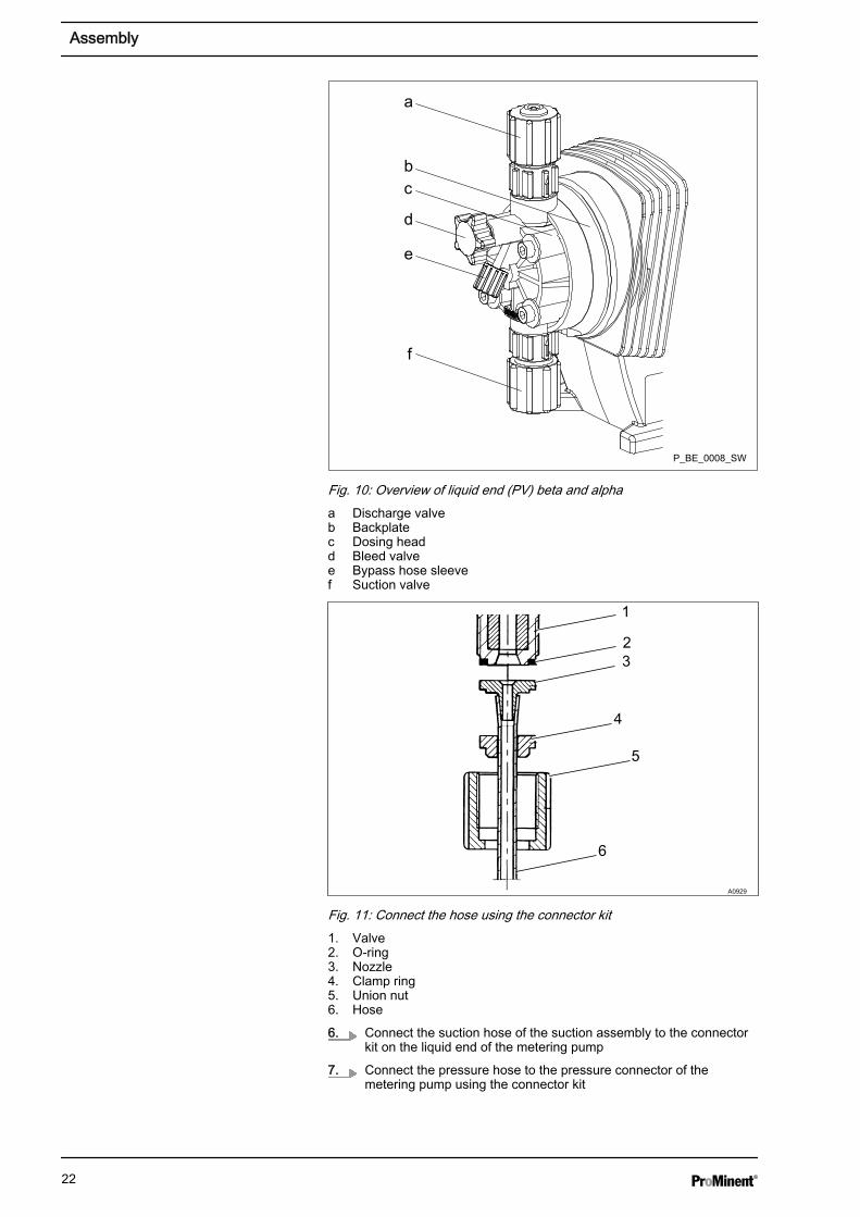
Fig. 10: Overview of liquid end (PV) beta and alphaa Discharge valveb Backplatec Dosing headd Bleed valvee Bypass hose sleevef Suction valve
1
23
4
5
6
A0929
Fig. 11: Connect the hose using the connector kit1. Valve2. O-ring3. Nozzle4. Clamp ring5. Union nut6. Hose
6. Connect the suction hose of the suction assembly to the connectorkit on the liquid end of the metering pump
7. Connect the pressure hose to the pressure connector of themetering pump using the connector kit
Assembly
22
8. Only alpha and Beta pump: Connect a suitable part of the suctionhose to the bleed valve of the pump and route the suction hoseback into the dosing tank
9. Connect the pressure hose to the injection valve using the con‐nector kit
The sample water should be free from air bubbles toensure reliable measurement and control.
1. Set a flow of 20 ... 60 l/h using the stopcock (read-off at the topedge of the float).
2. Check the hydraulic leak-tightness of the system (escaping liquid,continuous air bubbles in the in-line probe housing, ...)
ð Tighten the threaded connectors if necessary.
1.Have a collecting vessel at the ready
Open the sampling tap
2. If water flows out of the sampling tap, the system is not under nega‐tive pressure and is working correctly
If air is drawn in, this means that there is negativepressure in the system. In this case, throttle thevalve at the point at which the sample water pipeenters the filtration circuit - the pressure shouldnot exceed 1 bar.
3. Use the stopcock on the sample water drain to finely adjust thesystem
6.3.2 Sensors
Please refer to the operating instructions for the sensors.
1. Close the shut-off valves upstream and downstream of the in-lineprobe housing
2. Remove the transparent protective cap from the ball-shaped end ofthe pH sensor
3. Manually screw the pH sensors into separate threaded holes on thein-line probe housing. Then carefully tighten using an SW 17 open-ended spanner until the threaded connector is tight
4. Testing the sensors' hydraulic installation: Adjust the flow using theshut-off valve to 20... 60 l/h
ð Check whether the threaded connectors on the in-line probehousing are tight.
Testing the hydraulic installation of themetering system:
Check the system for negative pressure
pH sensor installation
Assembly
23
If there is already sample water in the in-line probehousingSlowly lower the sensor into the in-line probe housing.Otherwise the diaphragm of the sensor is overstretchedand the sensor delivers incorrect values.
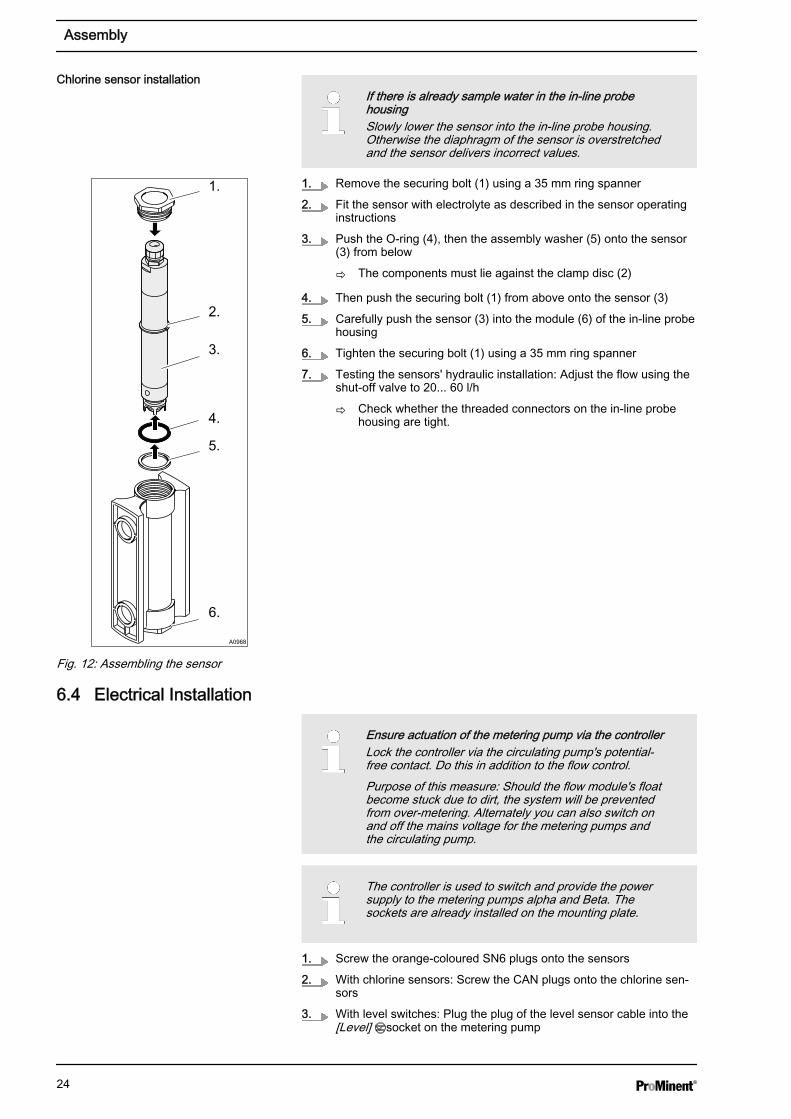
1. Remove the securing bolt (1) using a 35 mm ring spanner
2. Fit the sensor with electrolyte as described in the sensor operatinginstructions
3. Push the O-ring (4), then the assembly washer (5) onto the sensor(3) from below
ð The components must lie against the clamp disc (2)
4. Then push the securing bolt (1) from above onto the sensor (3)
5. Carefully push the sensor (3) into the module (6) of the in-line probehousing
6. Tighten the securing bolt (1) using a 35 mm ring spanner
7. Testing the sensors' hydraulic installation: Adjust the flow using theshut-off valve to 20... 60 l/h
ð Check whether the threaded connectors on the in-line probehousing are tight.
6.4 Electrical Installation
Ensure actuation of the metering pump via the controllerLock the controller via the circulating pump's potential-free contact. Do this in addition to the flow control.Purpose of this measure: Should the flow module's floatbecome stuck due to dirt, the system will be preventedfrom over-metering. Alternately you can also switch onand off the mains voltage for the metering pumps andthe circulating pump.
The controller is used to switch and provide the powersupply to the metering pumps alpha and Beta. Thesockets are already installed on the mounting plate.
1. Screw the orange-coloured SN6 plugs onto the sensors
2. With chlorine sensors: Screw the CAN plugs onto the chlorine sen‐sors
3. With level switches: Plug the plug of the level sensor cable into the[Level] socket on the metering pump
Chlorine sensor installation
A0968
1.
2.
3.
4.
5.
6.
Fig. 12: Assembling the sensor
Assembly
24
6.4.1 Connect power supplyProvide the following sockets for the power supply:
n Power supply of the controller, 230 V ± 10 % / 50/60 Hzn Power supply of the metering pump pH value (only Beta)n Power supply of the metering pump chlorine (only Beta)
It must be possible for the sockets to be de-energised from outside thedanger zone by appropriate measures (e.g. emergency stop switch etc.).
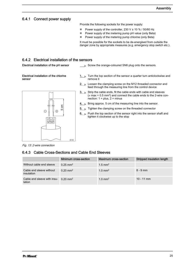
6.4.2 Electrical installation of the sensorsScrew the orange-coloured SN6 plug onto the sensors.
1. Turn the top section of the sensor a quarter turn anticlockwise andremove it
2. Loosen the clamping screw on the M12 threaded connector andfeed through the measuring line from the control device
3. Strip the cable ends, fit the cable ends with cable end sleeves(⌀ max = 0.5 mm2) and connect the cable ends to the 2-wire con‐nection: 1 = plus, 2 = minus
4. Bring approx. 5 cm of the measuring line into the sensor.
5. Tighten the clamping screw on the threaded connector
6. Push the top section of the sensor right into the sensor shaft andtighten it clockwise up to the stop
6.4.3 Cable Cross-Sections and Cable End Sleeves Minimum cross-section Maximum cross-section Stripped insulation length
Without cable end sleeve 0.25 mm2 1.5 mm2
Cable end sleeve withoutinsulation
0.20 mm2 1.0 mm2 8 - 9 mm
Cable end sleeve with insu‐lation
0.20 mm2 1.0 mm2 10 - 11 mm
Electrical installation of the pH sensor
Electrical installation of the chlorinesensor
A0102
Fig. 13: 2-wire connection
Assembly
25

7 Start Up
WARNING!Danger from hazardous substances!Possible consequence: Fatal or very serious injuries.
Please ensure when handling hazardous substancesthat you have read the latest safety data sheets providedby the manufacture of the hazardous substance. Theactions required are described in the safety data sheet.Check the safety data sheet regularly and replace, ifnecessary, as the hazard potential of a substance canbe re-evaluated at any time based on new findings.
The system operator is responsible for ensuring thatthese safety data sheets are available and that they arekept up to date, as well as for producing an associatedhazard assessment for the workstations affected.
WARNING!Acid and chlorine productsCause: Never bring together acid and chlorine products,like sodium-calcium hypochlorite as this will produce atoxic chlorine gas.
Possible consequence: Fatal or very serious injuriesfrom chlorine gas.
Action: refer to the current material safety data sheetsfor the feed chemicals.
CAUTION!Wear suitable protective equipment (gloves, protectivegoggles...) when commissioning.
Refer to the latest material safety data sheets on thefeed chemicals.
NOTICE!Close the sampling tap otherwise sample water willescape.
The service technician is responsible for instructingoperating and maintenance personnel during commis‐sioning.
Metering pumps alphaThe following applies to metering pumps alpha andBeta®:– The acid metering pump has a grey PP dosing head– The chlorine metering pump has a transparent clear
acrylic dosing head
If power sockets are available on the metering system,then always use the socket on the same side as themetering pump. The power socket is actuated so that itswitches the pump installed on the same side.
Preparation:
Start Up
26
Maximum permissible operating pressure:In the sample water line:– With chlorine sensor, 1 bar at 30 °C (sample water)– Without chlorine sensor, 2 bar at 30 °C (sample
water)
1. Tighten all threaded connectors prior to initial commissioning
2. Open the shut-off valves downstream of the metering pumps, in thesample water line and also the shut-off valves in your system
3. Insert the suction lances into the relevant chemical storage tanks foracid or disinfectant (e.g. sodium-calcium hypochlorite)
4. Plug the mains plug into the socket and switch on the mains voltage
7.1 Adjust the flow sensor switching point
Sample water may escape.
1. Adjust the flow to 50 l/h using the ball valve
2. Hold the flow sensor in place and loosen the mounting clip a little
3. Press the float to 40 l/h using the flow sensor
ð The error message should disappear.
4. Hold the flow sensor in this position and tighten the mounting clip
5. Then re-adjust the flow required using the ball valve
6. Acknowledge any error message that occurs
7. Reset any possible consequences of this in the overall installation
8. Check the threaded connector for leak-tightness
The flow sensor should switch when theflow falls (flow sensor is connected as anNC).
Start Up
27
7.2 Priming and bleeding (with an alpha or Beta pump)
WARNING!Danger from hazardous substances!Possible consequence: Fatal or very serious injuries.
Measure: The bleed valve must be equipped with atransparent PVC hose (6 x 4 mm). The PVC hose mustbe connected to the respective chemical storage tank sothat the leaking chemicals can flow back into the chem‐ical storage tank during the bleeding process.
DF2a and DF4a pumpsPriming and bleeding is not required with the self-primingDF2a and DF4a pumps.
1. Slightly open the bleed valve of the alpha or Beta metering pump
2.Stroke length for the Beta pumpIf possible, always operate the Beta pump with100% stroke length. Only reduce the stroke lengthto values between 100% ... 30% if overdosing fre‐quently occurs (overshooting the measuredvalues).
Note the stroke length of the metering pump and set it to a strokelength of 100% (only with the Beta pump)
3. Start the controller using the [START/STOP] key.
4. Allow the metering pump to run until the feed chemical leaks fromthe bleed valve.
5. Close the metering pump bleed valve.
6. If required, re-adjust the stroke length of the Beta pump to the orig‐inal value.
Re-start the control process: change to the continuousdisplay using the Change key and start the controllerusing the START/STOP key
7.3 Calibration
Necessity for calibrating the zero pointCalibration of the zero point is not generally necessary.A calibration of the zero point is only necessary if thesensor is operated at the lower limit of the measuringrange or if the 0.5 ppm sensor version is used.
Although various calibration methods are possible with the controller fitted,when used as a swimming pool controller, we generally recommend 2-point calibration of the pH sensor and calibration of the slope with thechlorine sensor.
Prime the feed chemical as follows (foralpha and Beta pumps)
Start Up
28
You have to regularly calibrate the pH sensor duringoperation. That means: 24 hours after initial calibrationand then weekly thereafter.Please take into account any deviating national regula‐tions.Only calibrate the pH sensor with the quality buffer solu‐tions pH 7 and pH 4.
WARNING!Danger from hazardous substances!Possible consequence: Fatal or very serious injuries.
Please ensure when handling hazardous substancesthat you have read the latest safety data sheets providedby the manufacture of the hazardous substance. Theactions required are described in the safety data sheet.Check the safety data sheet regularly and replace, ifnecessary, as the hazard potential of a substance canbe re-evaluated at any time based on new findings.
The system operator is responsible for ensuring thatthese safety data sheets are available and that they arekept up to date, as well as for producing an associatedhazard assessment for the workstations affected.
There must be a chlorine concentration of approx. 0.5 mg/l in the pool tobe able to calibrate the sensors.
Example (without depletion losses): A swimming pool contains 60 m3, byway of example. To obtain a chlorine concentration of 0.5 mg/l in thisswimming pool, approx. 0.20 litres of 12% sodium-calcium hypochlorite(density (ρ) 1.22 ± 0.02) are required.
Meter in the required quantity of sodium-calcium hypochlorite intothe filtration circuit, either using the chlorine metering pump orevenly distribute the quantity of sodium-calcium hypochloriteneeded into the swimming pool using a measuring cup
ð An even concentration can be expected once the reaction timehas elapsed:
Reaction time [h] = pool contents [m3] / circulation capacity[m3/h]
7.3.1 Chlorine calibration
Chlorine must be continuously present in the samplewater (approx 0.5 mg/l) for the whole period. Otherwisethe measuring system cannot calibrate.
Preparing the filtration circuit
Preparation for chlorine calibration andchlorine calibration
Start Up
29
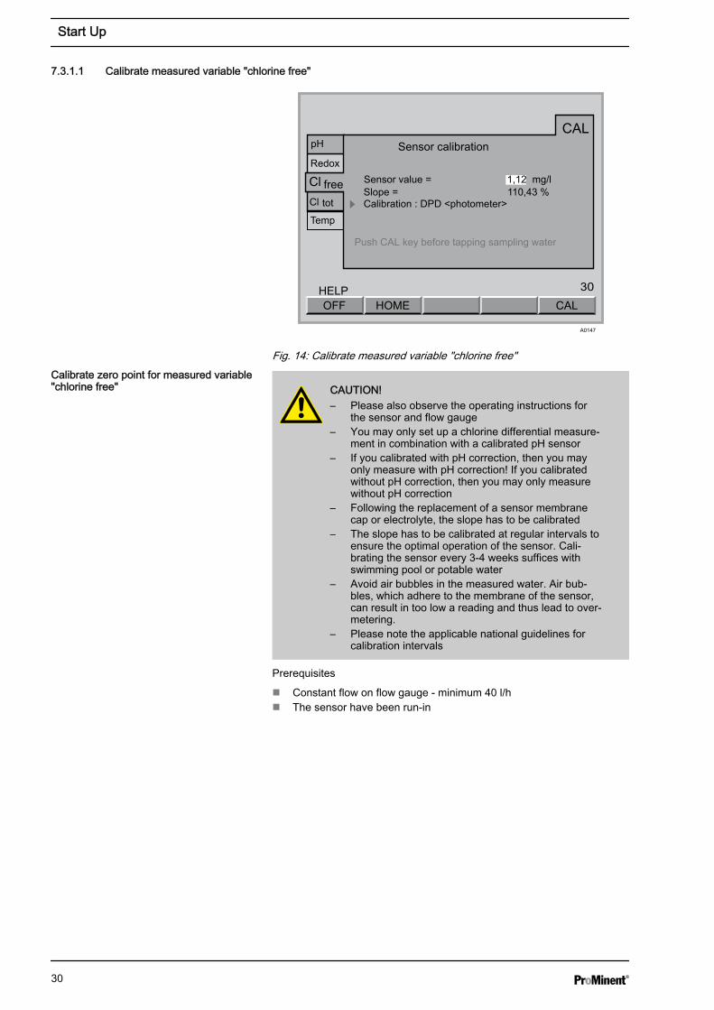
7.3.1.1 Calibrate measured variable "chlorine free"
30
CALHOMEOFFHELP
CAL
Redox
Cl
Cl
free
tot
Temp
Sensor calibration
Sensor value = 1,12 mg/lSlope = 110,43 %Calibration : DPD <photometer>
Push CAL key before tapping sampling water
pH
A0147
Fig. 14: Calibrate measured variable "chlorine free"
CAUTION!– Please also observe the operating instructions for
the sensor and flow gauge– You may only set up a chlorine differential measure‐
ment in combination with a calibrated pH sensor– If you calibrated with pH correction, then you may
only measure with pH correction! If you calibratedwithout pH correction, then you may only measurewithout pH correction
– Following the replacement of a sensor membranecap or electrolyte, the slope has to be calibrated
– The slope has to be calibrated at regular intervals toensure the optimal operation of the sensor. Cali‐brating the sensor every 3-4 weeks suffices withswimming pool or potable water
– Avoid air bubbles in the measured water. Air bub‐bles, which adhere to the membrane of the sensor,can result in too low a reading and thus lead to over-metering.
– Please note the applicable national guidelines forcalibration intervals
Prerequisites
n Constant flow on flow gauge - minimum 40 l/hn The sensor have been run-in
Calibrate zero point for measured variable"chlorine free"
Start Up
30
ESC
Central menu item
30
CAL DPDOFFHELP
CAL
Redox
Cl
Cl
free
tot
Temp
Sensor calibration
Sensor value = 1.12 mg/lSlope = 110.43 %
Calibration : DPD <photometer>
Push CAL key before tapping sampling water
pH
CAL
Redox
Cl
Cl
free
tot
Temp
Sensor calibration
Sensor value = 0.00 mg/lSlope = 110.43 %
Calibration : DPD <photometer>
Push CAL key before tapping sampling water
pH
Calibration Zero point CALOFF
HELP
CAL
Redox
Cl
Cl
free
tot
Temp
Sensor calibration
Sensor value = 0.00 mg/l
Slope = 110.43 %Calibration : Zero point
Immerse sensor in chlorine free water Wait until value has stabilised at approx. 0 mg/l Push CAL key
pH
HOME
INFOSensor calibration
Sensor value = 0.00 mg/lSlope = 142.26 %Zero point = 10.00 pA
CALOFFHELP
CAL
Redox
Cl
Cl
free
tot
Temp
Sensor calibration
Sensor value = 0.00 mg/l
Slope = 142.26 %Calibration : Zero point
Immerse sensor in chlorine free water Wait until value has stabilised at approx. 0 mg/l Push CAL key
pH
A0148
Zero point = 0.00 pA Zero point = 0.00 pA
Zero point
CAL
CAL
Cl free
Zero point Calibration
Sensor value = 0.00 mg/lSensor current = 10 pATemp. value = 25.6 °C
Calibration started. the calibration is finished with CAL! ESC cancels the calibration!
Calibration completed
Zero point
Zero point = 10.00 pA
Zero point = 10.00 pA
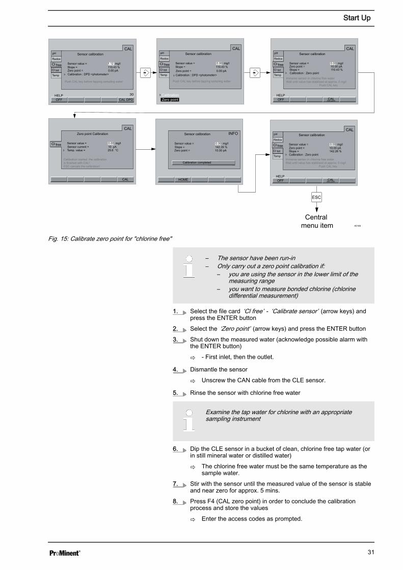
Fig. 15: Calibrate zero point for "chlorine free"
– The sensor have been run-in– Only carry out a zero point calibration if:
– you are using the sensor in the lower limit of themeasuring range
– you want to measure bonded chlorine (chlorinedifferential measurement)
1. Select the file card ‘Cl free’ - ‘Calibrate sensor’ (arrow keys) andpress the ENTER button
2. Select the ‘Zero point’ (arrow keys) and press the ENTER button
3. Shut down the measured water (acknowledge possible alarm withthe ENTER button)
ð - First inlet, then the outlet.
4. Dismantle the sensor
ð Unscrew the CAN cable from the CLE sensor.
5. Rinse the sensor with chlorine free water
Examine the tap water for chlorine with an appropriatesampling instrument
6. Dip the CLE sensor in a bucket of clean, chlorine free tap water (orin still mineral water or distilled water)
ð The chlorine free water must be the same temperature as thesample water.
7. Stir with the sensor until the measured value of the sensor is stableand near zero for approx. 5 mins.
8. Press F4 (CAL zero point) in order to conclude the calibrationprocess and store the values
ð Enter the access codes as prompted.
Start Up
31
9. Conclude calibration with the F5 key (CAL)
ð Display: [zero point calibration completed]
10. Press F2 (HOME)
ð Zero point calibration is completed.
11. You can now exit the menu with the ESC button
12. Re-install the sensor into the flow gauge
13. Open the shut-off valves for the measured water
ð First open the outlet, then the inlet.
14. Before calibrating the slope, wait until the measured value is con‐stant (minimum 15 mins)
15.CAUTION!Now it is imperative to calibrate the ‘slope’
ESC
Central menu item
CAL DPDOFFHELP
CAL
Redox
Cl
Cl
free
tot
Temp
Sensor calibration
Sensor value = 0.96 mg/lSlope = 110.43 %
Calibration : DPD <photometer>
Push CAL key before tapping sampling water
pH
INFO
CALOFFHELP
CAL
Redox
Cl
Cl
free
tot
Temp
Sensor calibration
Sensor value = 1.01 mg/lSlope = 132.71 %
Calibration : DPD <photometer>Push CAL key before tapping sampling water
pH
A0149
CAL
Cl free
DPD Calibration
Sensor value = 1.11 mg/lTemp. Value = 27.4 °C
DPD value : 1.01 mg/l
Measure chlorine concentration with photometer Enter value and push CAL keyCalibration started, the calibration is finished with CAL! ESC cancels the calibration!
KALOFFHELP
Sensor calibration
Sensor value = 1.01 mg/lSlope = 132.71 %Zero point = 10.00 pA
Zero point = 10.00 pA
DEFAULT INFO MESS
Calibration completed
HOME
CAL
Cl free
DPD Calibration
Sensor value = 1.01 mg/lTemp. Value = 27.4 °C
DPD value : 1.01 mg/l
Measure chlorine concentration with photometer Enter value and push CAL keyCalibration started, the calibration is finished with CAL! ESC cancels the calibration!
DPD VALUE =
Rng: 0.01 .. 10.00 mg/l01.01 mg/l
CAL
Cl free
DPD Calibration
Sensor value = 0.90 mg/lTemp. Value = 27.4 °C
DPD value : 1.30 mg/l
Measure chlorine concentration with photometer Enter value and push CAL keyCalibration started, the calibration is finished with CAL! ESC cancels the calibration!
CALOFFHELP
DEFAULT INFO MEAS
Zero point = 10.00 pA
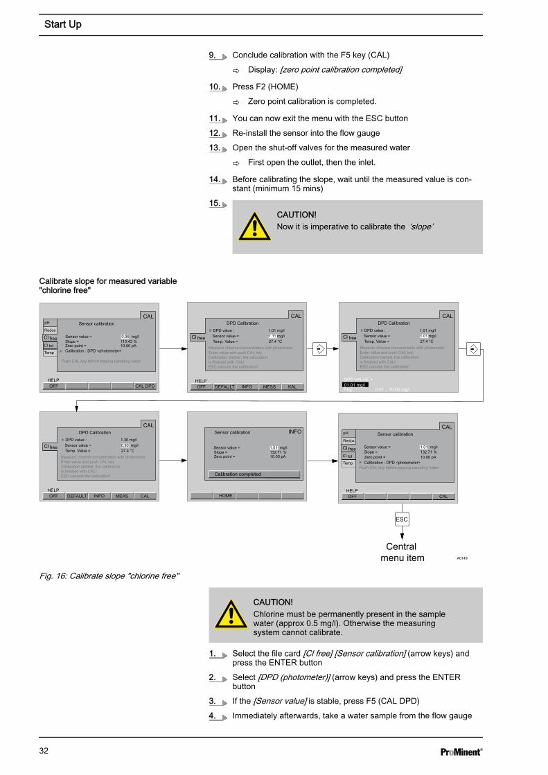
Fig. 16: Calibrate slope "chlorine free"
CAUTION!Chlorine must be permanently present in the samplewater (approx 0.5 mg/l). Otherwise the measuringsystem cannot calibrate.
1. Select the file card [Cl free] [Sensor calibration] (arrow keys) andpress the ENTER button
2. Select [DPD (photometer)] (arrow keys) and press the ENTERbutton
3. If the [Sensor value] is stable, press F5 (CAL DPD)
4. Immediately afterwards, take a water sample from the flow gauge
Calibrate slope for measured variable"chlorine free"
Start Up
32
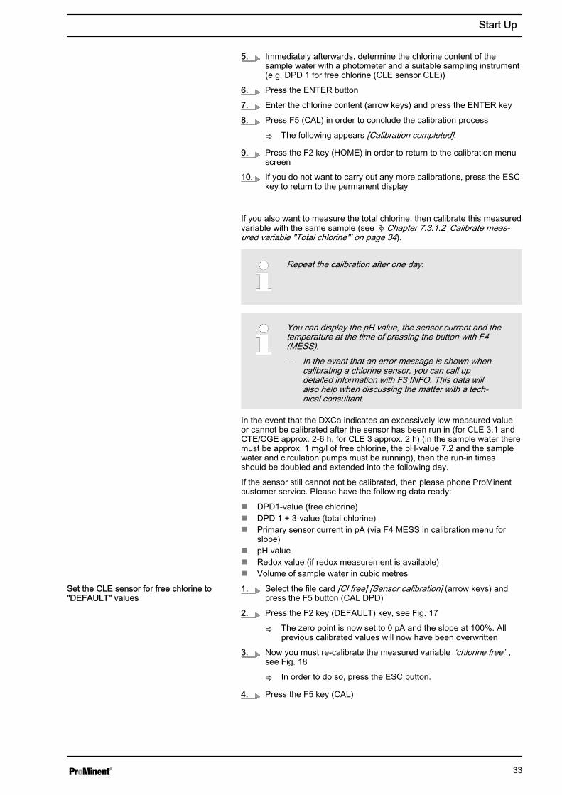
5. Immediately afterwards, determine the chlorine content of thesample water with a photometer and a suitable sampling instrument(e.g. DPD 1 for free chlorine (CLE sensor CLE))
6. Press the ENTER button
7. Enter the chlorine content (arrow keys) and press the ENTER key
8. Press F5 (CAL) in order to conclude the calibration process
ð The following appears [Calibration completed].
9. Press the F2 key (HOME) in order to return to the calibration menuscreen
10. If you do not want to carry out any more calibrations, press the ESCkey to return to the permanent display
If you also want to measure the total chlorine, then calibrate this measuredvariable with the same sample (see Ä Chapter 7.3.1.2 ‘Calibrate meas‐ured variable "Total chlorine"’ on page 34).
Repeat the calibration after one day.
You can display the pH value, the sensor current and thetemperature at the time of pressing the button with F4(MESS).– In the event that an error message is shown when
calibrating a chlorine sensor, you can call updetailed information with F3 INFO. This data willalso help when discussing the matter with a tech‐nical consultant.
In the event that the DXCa indicates an excessively low measured valueor cannot be calibrated after the sensor has been run in (for CLE 3.1 andCTE/CGE approx. 2-6 h, for CLE 3 approx. 2 h) (in the sample water theremust be approx. 1 mg/l of free chlorine, the pH-value 7.2 and the samplewater and circulation pumps must be running), then the run-in timesshould be doubled and extended into the following day.
If the sensor still cannot not be calibrated, then please phone ProMinentcustomer service. Please have the following data ready:
n DPD1-value (free chlorine)n DPD 1 + 3-value (total chlorine)n Primary sensor current in pA (via F4 MESS in calibration menu for
slope)n pH valuen Redox value (if redox measurement is available)n Volume of sample water in cubic metres
1. Select the file card [Cl free] [Sensor calibration] (arrow keys) andpress the F5 button (CAL DPD)
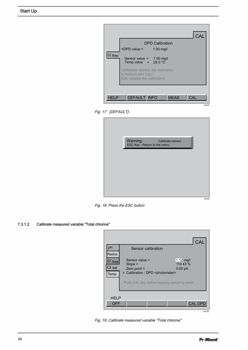
2. Press the F2 key (DEFAULT) key, see Fig. 17
ð The zero point is now set to 0 pA and the slope at 100%. Allprevious calibrated values will now have been overwritten
3. Now you must re-calibrate the measured variable ‘chlorine free’ ,see Fig. 18
ð In order to do so, press the ESC button.
4. Press the F5 key (CAL)
Set the CLE sensor for free chlorine to"DEFAULT" values
Start Up
33
HELP MEAS
CAL
Cl free
DPD Calibration
Temp.value = 25.0 °C
▶DPD value = 1.00 mg/l
Calibration started, the calibration is finished with CAL! ESC cancels the calibration!
=
CALA0335
DEFAULT INFO
Sensor value 1.00 mg/l
Fig. 17: [DEFAULT] .
Warning: Calibrate sensor
A0336
ESC Key - Return to the menu
Fig. 18: Press the ESC button
7.3.1.2 Calibrate measured variable "Total chlorine"
CAL DPDOFFHELP
CAL
Redox
Cl
Cl free
tot
Temp
pH Sensor calibration
Sensor value = 1.12 mg/lSlope = 110.43 %
Calibration : DPD <photometer>
Push CAL key before tapping sampling water
A0150
Zero point = 0.00 pA
Fig. 19: Calibrate measured variable "Total chlorine"
Start Up
34
CAUTION!– Here you calibrate the CTE sensor for total chlorine– The DXCa calculates the displayed value for bonded
chlorine as the difference between the measuredvalues from the free chlorine and total chlorine sen‐sors.
– The sensor for ‘Free chlorine’ must be a CLE 3.1sensor for the chlorine differential measurement
– Please also observe the operating instructions forthe sensor and flow gauge
– You may only set up a chlorine differential measure‐ment in combination with a calibrated pH sensor
– If you calibrated with pH correction, then you mayonly measure with pH correction! If you calibratedwithout pH correction, then you may only measurewithout pH correction
– Following the replacement of a sensor membranecap or electrolyte, the slope has to be calibrated
– The slope has to be calibrated at regular intervals toensure the optimal operation of the sensor. Cali‐brating the sensor every 3-4 weeks suffices withswimming pool or potable water
– Avoid air bubbles in the measured water. Air bub‐bles, which adhere to the membrane of the sensor,can result in too low a reading and thus lead to over-metering.
– Please note the applicable national guidelines forcalibration intervals
Prerequisites
n Constant flow on flow gauge - minimum 40 l/hn The sensor have been run-inn A CLE 3.1 sensor for free chlorine must be available in the system
(pools, filtration circuit, etc.)
ESC
Central menu item
30
CAL DPDOFFHELP
CAL
Redox
Cl
Cl
free
tot
Temp
Sensor calibration
Sensor value = 0.00 mg/lSlope = 145.06 %
Calibration : DPD <photometer>
Push CAL key before tapping sampling water
pH
CAL
Redox
Cl
Cl
free
tot
Temp
Sensor calibration
Sensor value = 0.00 mg/lSlope = 145.06 %
Calibration : DPD <photometer>
Push CAL key before tapping sampling water
pH
Calibration Zero point CALOFF
HELP
CAL
Redox
Cl
Cl
free
tot
Temp
Sensor calibration
Sensor value = 0.00 mg/l
Slope = 145.06 %Calibration : Zero point
Immerse sensor in chlorine free water Wait until value has stabilised at approx. 0 mg/l Push CAL key
pH
HOME
INFOSensor calibration
Sensor value = 0.00 mg/lSlope = 142.26 %Zero point = 0.00 pA
CALOFFHELP
CAL
Redox
Cl
Cl
free
tot
Temp
Sensor calibration
Sensor value = 0.00 mg/l
Slope = 142.26 %Calibration : Zero point
Immerse sensor in chlorine free water Wait until value has stabilised at approx. 0 mg/l Push CAL key
pH
A0151
Zero point = 0.00 pA Zero point = 0.00 pA
Zero point
OFF
CALCl tot Zero point calibration
Sensor value = 0.00 mg/lSensor current = 100 pA
Calibration started. the calibration is finished with CAL! ESC cancels the calibration!
Calibration completed
Zero point
Zero point = 0.00 pA
Zero point = 0.00 pA
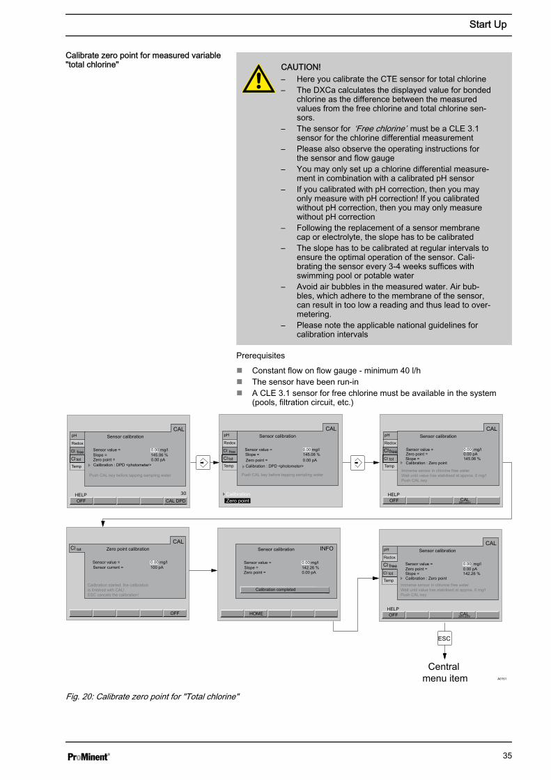
Fig. 20: Calibrate zero point for "Total chlorine"
Calibrate zero point for measured variable"total chlorine"
Start Up
35

– The sensor have been run-in– Only carry out a zero point calibration if:
– you are using the sensor in the lower limit of themeasuring range
– you want to measure bonded chlorine (chlorinedifferential measurement)
1. Select the file card ‘Cl comb’ - ‘Calibrate sensor’ (arrow keys) andpress the ENTER button
2. Select the ‘Zero point’ (arrow keys) and press the ENTER button
3. Shut down the measured water (acknowledge possible alarm withthe ENTER button)
ð - First inlet, then the outlet.
4. Dismantle the sensor
ð Do not unscrew the CAN cable from the CTE sensor.
5. Rinse the sensor with chlorine free water
Examine the tap water for chlorine with an appropriatesampling instrument
6. Dip the CTE sensor in a bucket of clean, chlorine free tap water (orin still mineral water or distilled water)
ð The chlorine free water must be the same temperature as thesample water.
7. Stir with the sensor until the measured value of the sensor is stableand near zero for approx. 5 mins.
8. Press F4 (CAL zero point) in order to conclude the calibrationprocess and store the values
ð Enter the access codes as prompted.
9. Conclude calibration with the F5 key (CAL)
ð Display: [zero point calibration completed]
10. Re-install the sensor into the flow gauge
11. Open the shut-off valves for the measured water
ð First open the outlet, then the inlet.
12. Before calibrating the slope, wait until the measured value is con‐stant (minimum 15 mins)
13.CAUTION!Now it is imperative to calibrate the ‘slope’
Start Up
36
ESC
Central menu item
CAL DPDOFFHELP
CAL
Redox
Cl
Clfree
tot
Temp
Sensor calibration
Sensor value = 1.65 mg/lSlope = 160.43 %
Calibration: DPD <photometer>
Push CAL key before tapping sampling water
pH
INFO
CAL DPDOFFHELP
CAL
Redox
Cl
Clfree
tot
Temp
Sensor calibration
Sensor value = 1.01 mg/lSlope = 132.71 %
Calibration: DPD <photometer>Push CAL key before tapping sampling water
pH
A0152
CALCl tot DPD-Calibration
Sensor value = 1.65 mg/lTemp. Value = 27.4 °C
DPD value: 1.01 mg/l
Measure chlorine concentration with photometer nter value and push CAL keyCalibration started, the calibration is finished with CAL! ESC cancels the calibration!
CALOFFHELP
Sensor calibration
Sensor value = 1.70 mg/lSlope = 232.71 %Zero point = 10.00 pA
Zero point = 10.00 pA
DEFAULT INFO MEAS
Calibration completed
HOME
CALCl tot DPD-Calibration
Sensor value = 1.01 mg/lTemp. Value = 27.4 °C
DPD value: 1.01 mg/l
Measure chlorine concentration with photometer nter value and push CAL keyCalibration started, the calibration is finished with CAL! ESC cancels the calibration!
DPD VALUE =
Rng: 0.01 .. 10.00 mg/l01.01 mg/l
CALCl tot DPD-Calibration
Sensor value = 0.90 mg/lTemp. Value = 27.4 °C
DPD value: 1.30 mg/l
Measure chlorine concentration with photometer nter value and push CAL keyCalibration started, the calibration is finished with CAL! ESC cancels the calibration!
CALOFFHELP
DEFAULT INFO MEAS
Zero point = 10.00 pA
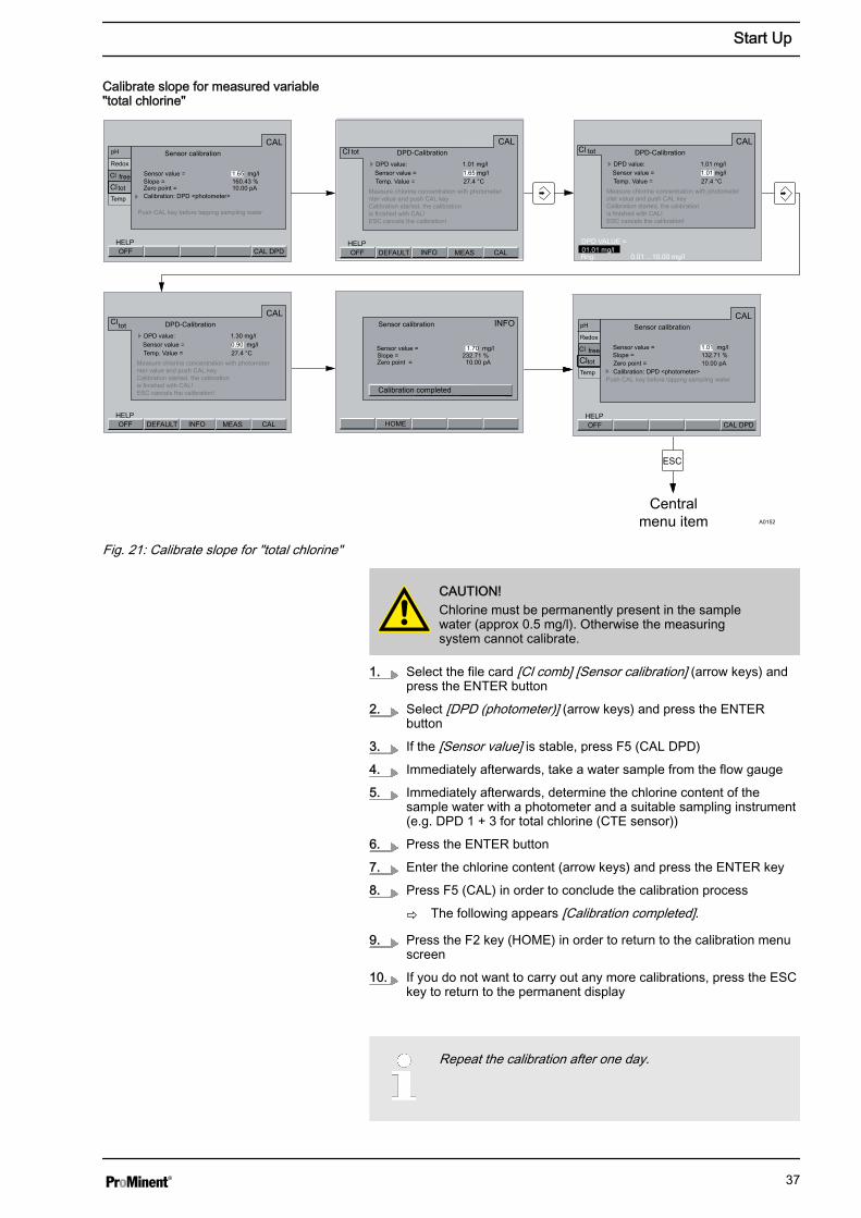
Fig. 21: Calibrate slope for "total chlorine"
CAUTION!Chlorine must be permanently present in the samplewater (approx 0.5 mg/l). Otherwise the measuringsystem cannot calibrate.
1. Select the file card [Cl comb] [Sensor calibration] (arrow keys) andpress the ENTER button
2. Select [DPD (photometer)] (arrow keys) and press the ENTERbutton
3. If the [Sensor value] is stable, press F5 (CAL DPD)
4. Immediately afterwards, take a water sample from the flow gauge
5. Immediately afterwards, determine the chlorine content of thesample water with a photometer and a suitable sampling instrument(e.g. DPD 1 + 3 for total chlorine (CTE sensor))
6. Press the ENTER button
7. Enter the chlorine content (arrow keys) and press the ENTER key
8. Press F5 (CAL) in order to conclude the calibration process
ð The following appears [Calibration completed].
9. Press the F2 key (HOME) in order to return to the calibration menuscreen
10. If you do not want to carry out any more calibrations, press the ESCkey to return to the permanent display
Repeat the calibration after one day.
Calibrate slope for measured variable"total chlorine"
Start Up
37
You can display the pH value, the sensor current and thetemperature at the time of pressing the button with F4(MESS).– In the event that an error message is shown when
calibrating a chlorine sensor, you can call updetailed information with F3 INFO. This data willalso help when discussing the matter with a tech‐nical consultant.
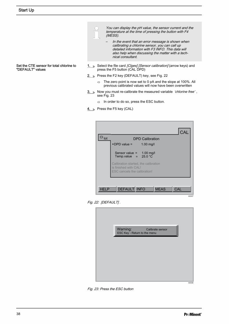
1. Select the file card [Clges] [Sensor calibration] (arrow keys) andpress the F5 button (CAL DPD)
2. Press the F2 key (DEFAULT) key, see Fig. 22
ð The zero point is now set to 0 pA and the slope at 100%. Allprevious calibrated values will now have been overwritten
3. Now you must re-calibrate the measured variable ‘chlorine free’ ,see Fig. 23
ð In order to do so, press the ESC button.
4. Press the F5 key (CAL)
HELP MEAS
CALCl tot DPD Calibration
Temp.value = 25.0 °C
▶DPD value = 1.00 mg/l
Calibration started, the calibration is finished with CAL! ESC cancels the calibration!
=
CALA0337
DEFAULT INFO
Sensor value 1.00 mg/l
Fig. 22: [DEFAULT] .
Warning: Calibrate sensor
A0336
ESC Key - Return to the menu
Fig. 23: Press the ESC button
Set the CTE sensor for total chlorine to"DEFAULT" values
Start Up
38
7.3.2 ORP calibrationYou need the following materials:
n Spray bottle with distilled watern Clean, soft clothn Buffer solution 465 mV (50 ml)
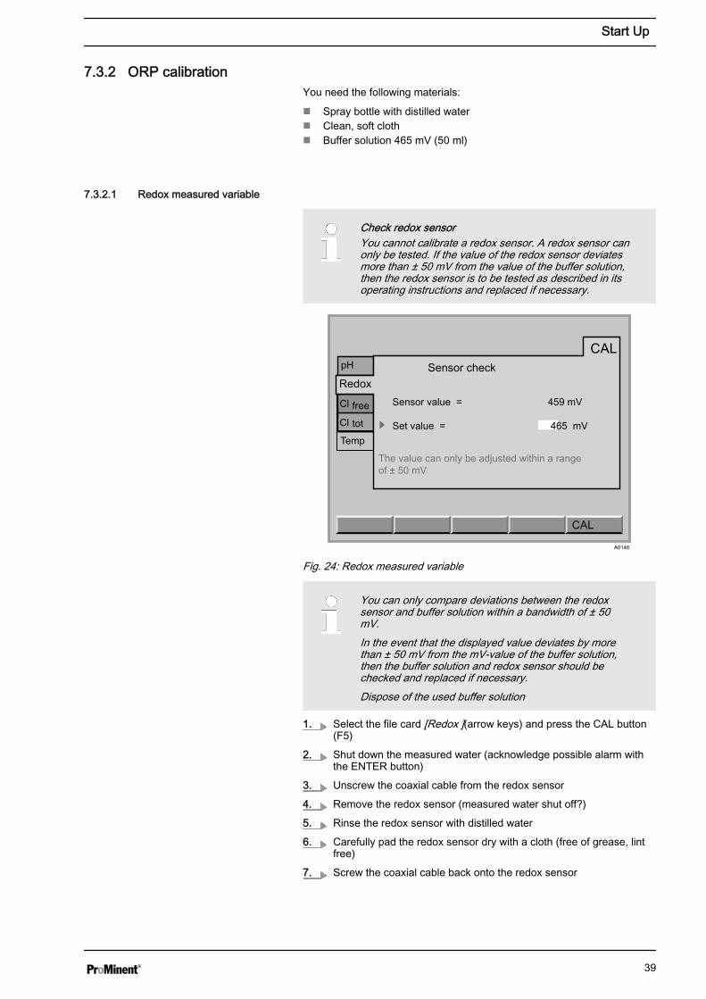
7.3.2.1 Redox measured variable
Check redox sensorYou cannot calibrate a redox sensor. A redox sensor canonly be tested. If the value of the redox sensor deviatesmore than ± 50 mV from the value of the buffer solution,then the redox sensor is to be tested as described in itsoperating instructions and replaced if necessary.
CAL
CAL
Redox
Cl
Cl
free
tot
Temp
Sensor check
Sensor value = 459 mV
Set value = 465 mV
The value can only be adjusted within a rangeof ± 50 mV
pH
A0146
Fig. 24: Redox measured variable
You can only compare deviations between the redoxsensor and buffer solution within a bandwidth of ± 50mV.In the event that the displayed value deviates by morethan ± 50 mV from the mV-value of the buffer solution,then the buffer solution and redox sensor should bechecked and replaced if necessary.Dispose of the used buffer solution
1. Select the file card [Redox ](arrow keys) and press the CAL button(F5)
2. Shut down the measured water (acknowledge possible alarm withthe ENTER button)
3. Unscrew the coaxial cable from the redox sensor
4. Remove the redox sensor (measured water shut off?)
5. Rinse the redox sensor with distilled water
6. Carefully pad the redox sensor dry with a cloth (free of grease, lintfree)
7. Screw the coaxial cable back onto the redox sensor
Start Up
39
8. Dip the redox sensor in a buffer solution (e.g. with 465 mV).
If you are measuring with an equipotential bondingpin, then also dip this into the buffer solution.
9. If the displayed value is stable, compare it with the specified mVvalue detailed on the buffer solution bottle - it may not vary morethan ± 50 mV from the buffer value
10. Press the ENTER button
11. Adjust the set value with the arrow keys. You can only comparedeviations between the redox sensor and buffer solution within abandwidth of ± 50 mV.
12. Press the ENTER button
13. Press the F5 key (ACCEPT)
14. If you do not want to carry out any more tests, press the ESC key toreturn to the permanent display or central menu item
15. Unscrew the coaxial cable from the redox sensor
16. Re-install the redox sensor into the flow gauge
17. Screw the coaxial cable back onto the redox sensor
18. Re-install the equipotential bonding pin
19. Open the shut-off valves for the measured water
ð First open the outlet, then the inlet.
7.3.3 calibration pHYou need the following materials:
n Spray bottle with distilled watern Clean, soft clothn Buffer solution pH 7 (50 ml)n Buffer solution pH 4 (50 ml)
For this purpose, prepare for removal of the pH sensor, see the operatinginstructions for the sensors and the in-line probe housing.
Start Up
40
7.3.3.1 1-Point calibration pH
A0142
CALOFFHILFE
BUFFER
CALpH pH
Sensor value = pH 7.12 Buffer temp. = 26.7 °CBuffer value = 7.00 pH
Clean probe and put in buffer Start buffer recognition with BUFFER keyAdjust buffer temperature and value Push CAL key
Spring 1
10
HOMEOFFHILFE
CAL 1Pt
CALpHRedox
Cl
Cl
free
tot
Temp
Sensor calibration pH
Sensor value pH 7.12Zero point 0.24 mVSlope = 59.23 mV/pH
CAL 1Pt: Calibration with reference valueor buffer solution
CAL2Pt: Calibration with 2 buffer solutions
==
KAL2Pkt
A0142
CALOFFHILFE
PUFFER
CALpH pH
Sensor value = pH 7.12 Buffer temp. = 26.7 °CBuffer value = 7.00 pH
Clean probe and put in buffer Start buffer recognition with BUFFER keyAdjust buffer temperature and value Push CAL key
Spring 1
A0143
CALOFFHELP
PUFFER
CALpH pH
Sensor value = pH 7.12 Buffer temp. = 26.7 °CBuffer value = 7.00 pH
Clean probe and put in buffer Start buffer recognition with BUFFER keyAdjust buffer temperature and value Push CAL key
Spring 1
Buffer recognition runnin
A0144
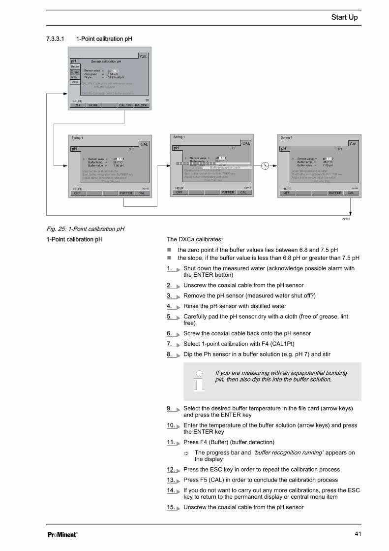
Fig. 25: 1-Point calibration pHThe DXCa calibrates:
n the zero point if the buffer values lies between 6.8 and 7.5 pHn the slope, if the buffer value is less than 6.8 pH or greater than 7.5 pH
1. Shut down the measured water (acknowledge possible alarm withthe ENTER button)
2. Unscrew the coaxial cable from the pH sensor
3. Remove the pH sensor (measured water shut off?)
4. Rinse the pH sensor with distilled water
5. Carefully pad the pH sensor dry with a cloth (free of grease, lintfree)
6. Screw the coaxial cable back onto the pH sensor
7. Select 1-point calibration with F4 (CAL1Pt)
8. Dip the Ph sensor in a buffer solution (e.g. pH 7) and stir
If you are measuring with an equipotential bondingpin, then also dip this into the buffer solution.
9. Select the desired buffer temperature in the file card (arrow keys)and press the ENTER key
10. Enter the temperature of the buffer solution (arrow keys) and pressthe ENTER key
11. Press F4 (Buffer) (buffer detection)
ð The progress bar and ‘buffer recognition running’ appears onthe display
12. Press the ESC key in order to repeat the calibration process
13. Press F5 (CAL) in order to conclude the calibration process
14. If you do not want to carry out any more calibrations, press the ESCkey to return to the permanent display or central menu item
15. Unscrew the coaxial cable from the pH sensor
1-Point calibration pH
Start Up
41
16. Re-install the pH sensor into the flow gauge
17. Screw the coaxial cable back onto the pH sensor
18. Re-install the equipotential bonding pin
19. Open the shut-off valves for the measured water
ð First open the outlet, then the inlet.
7.3.3.2 2-Point calibration pH
CALOFFHELP
BUFFER
CALpH pH
Sensor value = pH 4.57 Buffer temp. = 26.7 °CBuffer value = 7.00 pH
Clean probe and put in buffer Start buffer recognition with BUFFER keyAdjust buffer temperature and value Push CAL key
Spring 1
Buffer recognition running
CALOFFHELP
BUFFER
CALpH pH
Sensor value = pH 7.12 Buffer temp. = 26,7 °CBuffer value = 7.00 pH
Clean probe and put in buffer Start buffer recognition with BUFFER keyAdjust buffer temperature and value Push CAL key
Spring 1
Buffer recognition running
A0145
CALOFFHELP
BUFFER
CALpH pH
Sensor value = pH 4.57 Buffer temp. = 26.7 °CBuffer value = 4.00 pH
Clean probe and put in buffer Start buffer recognition with BUFFER keyAdjust buffer temperature and value Push CAL key
Spring 1
Buffer 1
CALOFFHELP
BUFFER
CALpH pH
Sensor value = pH 4.57 Buffer temp. = 26.7 °CBuffer value = 4.00 pH
Clean probe and put in buffer Start buffer recognition with BUFFER keyAdjust buffer temperature and value Push CAL key
Spring 1
Buffer 1
CALOFFHELP
BUFFER
CALpH pH
Sensor value = pH 7.12 Buffer temp. = 26.7 °CBuffer value = 7.00 pH
Clean probe and put in buffer Start buffer recognition with BUFFER keyAdjust buffer temperature and value Push CAL key
Spring 1
Buffer 2 Buffer 2
Buffer 1
10
HOMEOFFHELP
CAL1Pt
CALpHRedox
Cl
Cl
free
tot
Temp
Sensor calibration pH
Sensor value pH 7.12Nullpunkt 0.24 mVSlope = 59.23 mV/pH
CAL1Pt: Calibration with reference value or buffer solution
CAL2Pt: Calibration with 2 buffer solutions
==
CAL2Pt
CALOFFHELP
BUFFER
CALpH pH
Sensor value = pH 7.12 Buffer temp. = 26.7 °CBuffer value = 7.00 pH
Clean probe and put in buffer Start buffer recognition with BUFFER keyAdjust buffer temperature and value Push CAL key
Quelle 1
Buffer 2
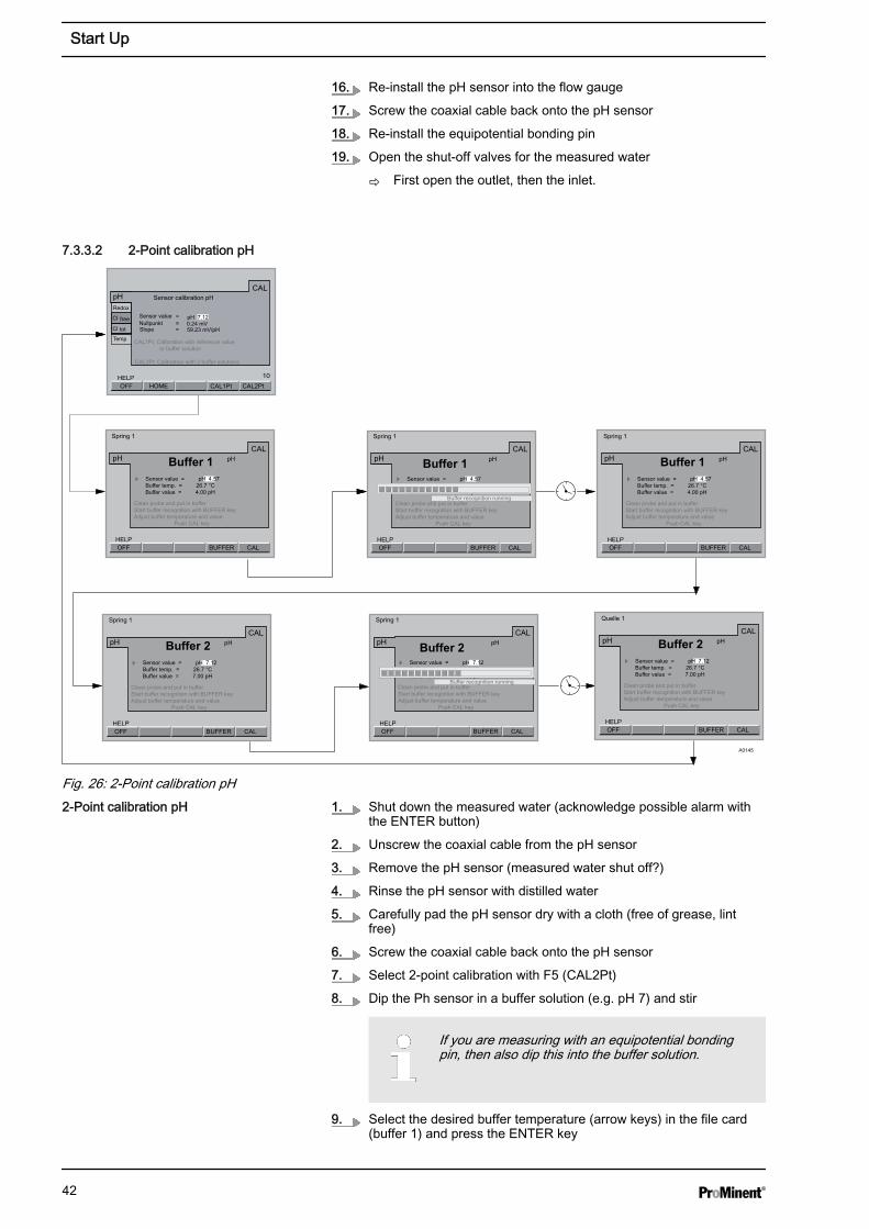
Fig. 26: 2-Point calibration pH1. Shut down the measured water (acknowledge possible alarm with
the ENTER button)
2. Unscrew the coaxial cable from the pH sensor
3. Remove the pH sensor (measured water shut off?)
4. Rinse the pH sensor with distilled water
5. Carefully pad the pH sensor dry with a cloth (free of grease, lintfree)
6. Screw the coaxial cable back onto the pH sensor
7. Select 2-point calibration with F5 (CAL2Pt)
8. Dip the Ph sensor in a buffer solution (e.g. pH 7) and stir
If you are measuring with an equipotential bondingpin, then also dip this into the buffer solution.
9. Select the desired buffer temperature (arrow keys) in the file card(buffer 1) and press the ENTER key
2-Point calibration pH
Start Up
42

10. Enter the temperature of the buffer solution (arrow keys) and pressthe ENTER key
11. Press F4 (Buffer) (buffer detection)
ð The progress bar and ‘buffer recognition running’ appears onthe display
The DXCa has detected and stored the value of the buffer solu‐tion pH 7 (buffer 1)
12. Press the ESC key in order to repeat the calibration process
13. Press the F5 key (CAL) in order to continue with calibration
14. Take the pH sensor out of the buffer pH7 (buffer 1) and rinse it withdistilled water
15. Carefully pad the pH sensor dry with a cloth (free of grease, lintfree)
16. Dip the Ph sensor in the buffer solution pH 4 (buffer 2) and stir
If you are measuring with an equipotential bondingpin, then also dip this into the buffer solution.
17. Select the desired buffer temperature (arrow keys) in the currentlydisplayed file card (buffer 2) and press the ENTER key
18. Enter the temperature of the buffer solution (arrow keys) and pressthe ENTER key
19. Press F4 (Buffer) (buffer detection)
ð The progress bar and ‘buffer recognition running’ appears onthe display
The DXCa has detected and stored the value of the buffer solu‐tion pH 4 (buffer 2)
20. Press the ESC key in order to repeat calibration
21. Press F5 (CAL) in order to conclude the calibration process andstore the values.
ð If calibration is successful, the following appears briefly:‘Calibration OK’ .
22. If you do not want to carry out any more calibrations, press the ESCkey to return to the permanent display or central menu item
23. Unscrew the coaxial cable from the pH sensor
24. Re-install the pH sensor into the flow gauge
25. Screw the coaxial cable back onto the pH sensor
26. Re-install the equipotential bonding pin
27. Open the shut-off valves for the measured water
ð First open the outlet, then the inlet.
Start Up
43
8 Maintenance
WARNING!Danger from hazardous substances!Possible consequence: Fatal or very serious injuries.
Please ensure when handling hazardous substancesthat you have read the latest safety data sheets providedby the manufacture of the hazardous substance. Theactions required are described in the safety data sheet.Check the safety data sheet regularly and replace, ifnecessary, as the hazard potential of a substance canbe re-evaluated at any time based on new findings.
The system operator is responsible for ensuring thatthese safety data sheets are available and that they arekept up to date, as well as for producing an associatedhazard assessment for the workstations affected.
Observe the operating instructions for the meteringpump (optional), in-line probe housing, sensors, dirt filterand multifunctional valve (optional).Thoroughly flush the metering system with water beforecarrying out maintenance.Regularly calibrate the sensors. That means: 24 hoursafter initial calibration and then weekly thereafter. Takeinto account any differing national regulations.
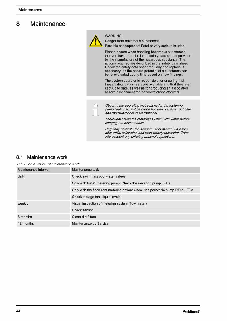
8.1 Maintenance workTab. 3: An overview of maintenance workMaintenance interval Maintenance task
daily Check swimming pool water values
Only with Beta® metering pump: Check the metering pump LEDs
Only with the flocculant metering option: Check the peristaltic pump DF4a LEDs
Check storage tank liquid levels
weekly Visual inspection of metering system (flow meter)
Check sensor
6 months Clean dirt filters
12 months Maintenance by Service
Maintenance
44
Check the current swimming pool water values daily toguarantee the safe operation of your swimming poolsystem.
1. Check the chlorine concentration using the DPD test (refer to theoperating instructions for the test kit)
2. Check the pH value using the phenol red test (refer to the operatinginstructions for the test kit)
ð If the swimming pool water values lie outside the tolerancelimits, then conduct additional tests, as described inÄ Tab. 3 ‘An overview of maintenance work’ on page 44.
3. Check the liquid levels in the storage tanks
ð Pour in feed chemical if the liquid level has fallen below 10 cm.
4. Only with Beta® metering pump: Check the LEDs on the meteringpumps. Call Service if:
n the red LED lights upn the green LED does not light up
5. Only with the DF4a peristaltic pump (flocculant): Check the LEDs onthe peristaltic pumps. Call Service if:
n the red LED lights upn the green LED does not light up
1. Regularly conduct a visual inspection of the metering system, spe‐cifically the sensors and the flow meter with flow sensor for:
n Air bubbles in the sample watern The state of the sensorsn Leakagesn Correct flow valuesn To ascertain whether the flow sensor is fastened correctly onto
the flow metern To ascertain whether the float is moving easily within the flow
meter: To do so, note down the flow value and then change theflow value - the float should change position
ð Call Service if one of these points is not correct.
2. Check the sensors by calibrating them
1. Close the stopcocks upstream and downstream of the in-line probehousing
2. Unscrew the filter bowl
3. Remove the filter insert and clean it without detergent
4. Insert the filter insert into the housing
5. Check the sealing ring and the sealing surfaces for cleanliness, andclean if necessary
6. Screw the filter bowl until tight
7. Open the stopcocks on the in-line probe housing
Maintenance interval: daily
Maintenance interval: weekly
Maintenance interval: at least every 6months
Clean dirt filter regularly:
Maintenance
45
Maintenance should be carried out by an authorised service.
8.2 Replacing the chemical storage tanks
WARNING!Danger from hazardous substances!Possible consequence: Fatal or very serious injuries.
Please ensure when handling hazardous substancesthat you have read the latest safety data sheets providedby the manufacture of the hazardous substance. Theactions required are described in the safety data sheet.Check the safety data sheet regularly and replace, ifnecessary, as the hazard potential of a substance canbe re-evaluated at any time based on new findings.
The system operator is responsible for ensuring thatthese safety data sheets are available and that they arekept up to date, as well as for producing an associatedhazard assessment for the workstations affected.
Labelling the chemical storage tanksLabel the connections on the unit, the metering accesso‐ries and the chemical storage tanks in such a way that itis impossible to mix up the storage tanks. It is theresponsibility of the system operator to attach and main‐tain the labels. We can provide labels.
1. Ensure unrestricted access to the chemical storage tanks to bereplaced so that you can work safely and keep escape routes free
2. Wear protective equipment as outlined in the material safety datasheets for the chemicals used
3. First replace one chemical storage tank and complete this task first
4. Handle and remove any spilt feed chemical as per the materialsafety data sheet
5. Only then replace the second chemical storage tank, if necessary,and complete this task first
6. Handle and remove any spilt feed chemical as per the materialsafety data sheet
7. Dispose of the empty chemical storage tanks as per the materialsafety data sheet
8.3 TroubleshootingUse the operating instructions for controllers, sensors, in-line probe hous‐ings, metering pumps and multifunctional valves (optional) to eliminatefunctional faults or call Customer service.
Maintenance interval: 12 months
Service
Maintenance
46
8.4 Disposal of Used Partsn User qualification: instructed user, see Ä Chapter 3.1 ‘Users' qualifi‐
cations’ on page 10
NOTICE!Regulations governing the disposal of used parts– Note the current national regulations and legal
standards which apply in your country
The manufacturer will take back decontaminated used units providing theyare covered by adequate postage.
Decontaminate the unit before returning it for repair. To do so, remove alltraces of hazardous substances. Refer to the Material Safety Data Sheetfor your feed chemical.
A current Declaration of Decontamination is available to download on theProMinent website.
Maintenance
47

9 Drawings, Drilling and External Dimensions of the DUL‐CODOS®
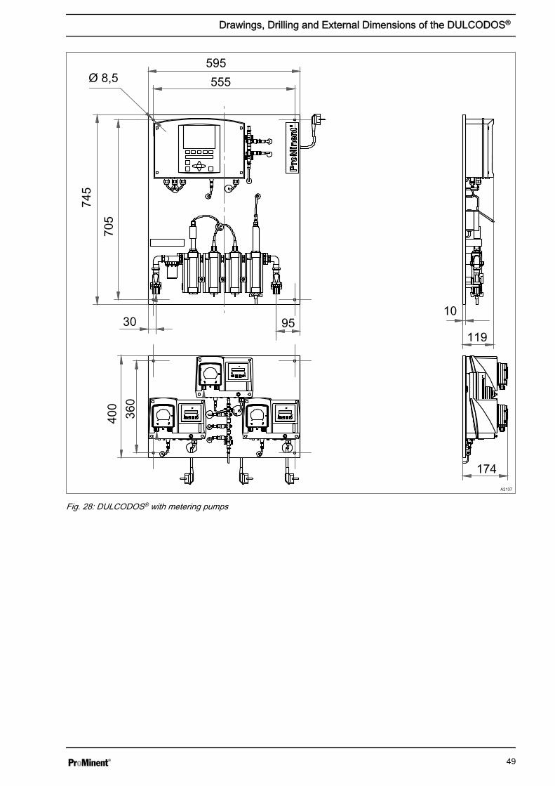
Versions of the DULCODOS®
The drawings show three possible versions of the DUL‐CODOS®. The drilling and external dimensions of theDULCODOS® are identical with all versions.
A2138
595
555
953010
119
745
705
Ø 8,5
Fig. 27: DULCODOS® without metering pumps
Drawings, Drilling and External Dimensions of the DULCODOS®
48
595555
30 95
Ø 8,574
5
705
174
119
10
400
360
A2137
Fig. 28: DULCODOS® with metering pumps
Drawings, Drilling and External Dimensions of the DULCODOS®
49
A0994
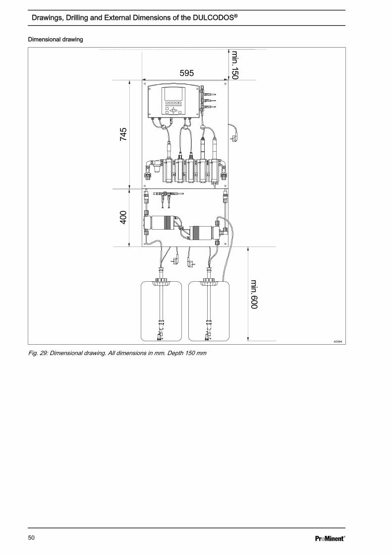
Fig. 29: Dimensional drawing. All dimensions in mm. Depth 150 mm
Dimensional drawing
Drawings, Drilling and External Dimensions of the DULCODOS®
50
10 Technical Data
Refer to the product-specific operating instructions fortechnical data on the controller, sensors, in-line probehousing, metering pump and multifunctional valve.
Maximum permissible operating pressure
n In the sample water line:– without a chlorine sensor: 2 bar at 30 °C (sample water)– with a chlorine sensor: 1 bar at 30 °C (sample water)
Sample water line connector
n 8 x 5 mm PE hose
Sample water filter element
n 300 µm
Weight
n with pumps: approx. 12 kgn without pumps: approx. 7 kg
Materials
n Plate material: PPn Materials, wetted: The wetted materials are resistant to the media
commonly used in swimming pools. Consult the operating instructionsfor the individual components for use with other media.
n Sample water filter: polypropylene, nylon, nitrile rubber, stainless steel
Technical Data
51
11 Spare Parts and AccessoriesTab. 4: Spare partsSpare parts Order no.
Chlorine sensor CLE 3.1-CAN-10 ppm (for free chlorine) with electrolyte, 100 ml 1023426
Spare diaphragm cap for CLE 3, CLE 3.1 815073
Electrolyte solution for chlorine sensor for CLE, 50 ml 506270
Chlorine sensor CTE 1-CAN -10 ppm (for total chlorine) with electrolyte, 100 ml 1023427
Chlorine sensor CGE 2-CAN-10 ppm (for total chlorine) 1024420
Spare diaphragm cap for CTE, CGE 792862
Electrolyte solution for chlorine sensors CTE, CGE, 50 ml 792892
pH sensor PHES 112 SE 150702
Buffer solution pH 7, 50 ml 506253
Buffer solution pH 4, 50 ml 506251
ORP Sensor RHES-Pt-SE 150703
Buffer solution 465 mV, 50 ml 506240
Filter element 300 µm, stainless steel 1038867
PC8 only: Filter element 350 µm, nylon 1021337
Tab. 5: The following table shows the assignment of the maintenance kits to the types of metering pumps used. Product
rangePump type Order number
Hose, complete 4.8 x 8.0 PharMed® DF2a 0208, 0216, 0224 1009480
Hose, complete 1.6 x 4.8 PharMed® DF4a 04015 1030722
Hose, complete 3.2 x 6.4 PharMed® DF4a 03060 1030723
Spare parts kit 1005-2/1605-2 PVT ALPc 1002PVT/1004PVT (ALPc) 1023110
Spare parts kits 1601 – 2 PVT, PPT, NPT BT4b 0401PVT (BT4b) 1023108
Spare parts kits 1602 – 2 PVT, PPT, NPT BT4b 0402PVT (BT4b) 1023109
Spare parts kits 1604 – 2 PVT, PPT, NPT BT4b 0404PVT 1035332
Spare parts kits for metering pumps Beta® comprise:
n 1 x diaphragmn 1 x suction valve, fully assembledn 1 x discharge valve, fully assembledn 2 x valve ballsn 1 x set of sealsn 1 x connector kit
Maintenance kits have been put together for the measured variables of theDULCODOS® Pool. Depending on the measured variable, the mainte‐nance kits consist of:
n Buffer solutionsn Electrolytesn Diaphragm caps
Maintenance kits for metering pumps
Maintenance kits for measured variables
Spare Parts and Accessories
52
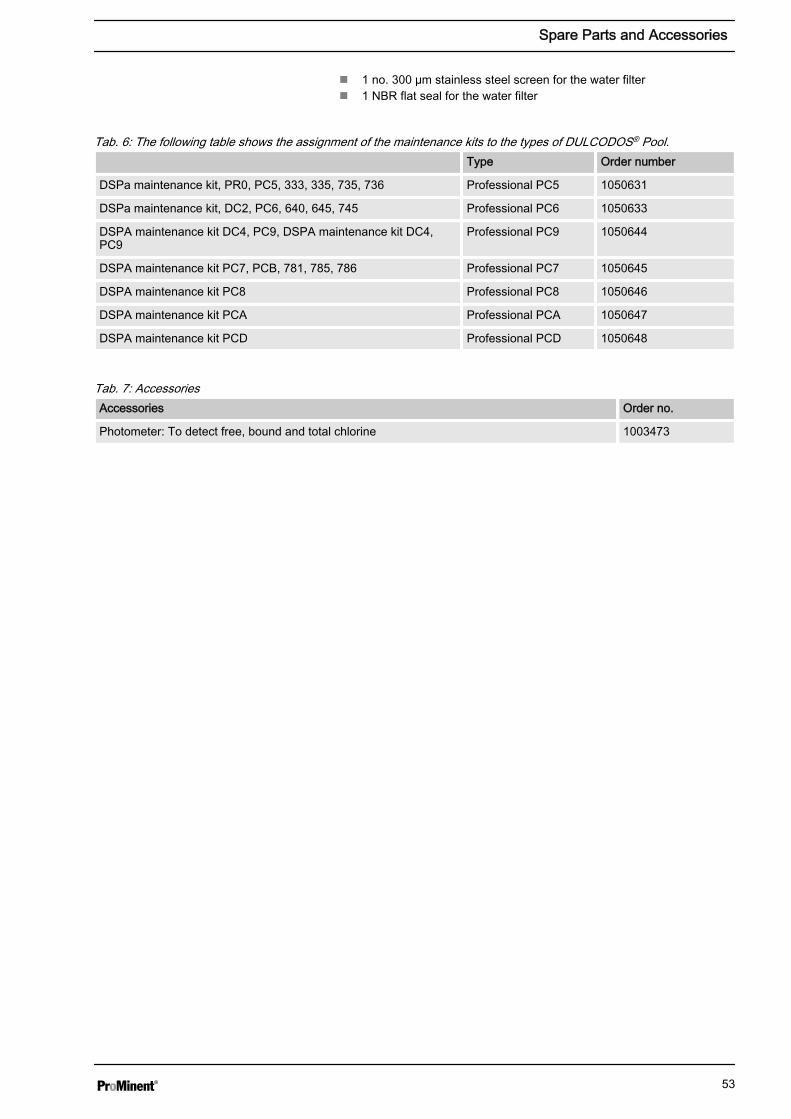
n 1 no. 300 µm stainless steel screen for the water filtern 1 NBR flat seal for the water filter
Tab. 6: The following table shows the assignment of the maintenance kits to the types of DULCODOS® Pool. Type Order number
DSPa maintenance kit, PR0, PC5, 333, 335, 735, 736 Professional PC5 1050631
DSPa maintenance kit, DC2, PC6, 640, 645, 745 Professional PC6 1050633
DSPA maintenance kit DC4, PC9, DSPA maintenance kit DC4,PC9
Professional PC9 1050644
DSPA maintenance kit PC7, PCB, 781, 785, 786 Professional PC7 1050645
DSPA maintenance kit PC8 Professional PC8 1050646
DSPA maintenance kit PCA Professional PCA 1050647
DSPA maintenance kit PCD Professional PCD 1050648
Tab. 7: AccessoriesAccessories Order no.
Photometer: To detect free, bound and total chlorine 1003473
Spare Parts and Accessories
53
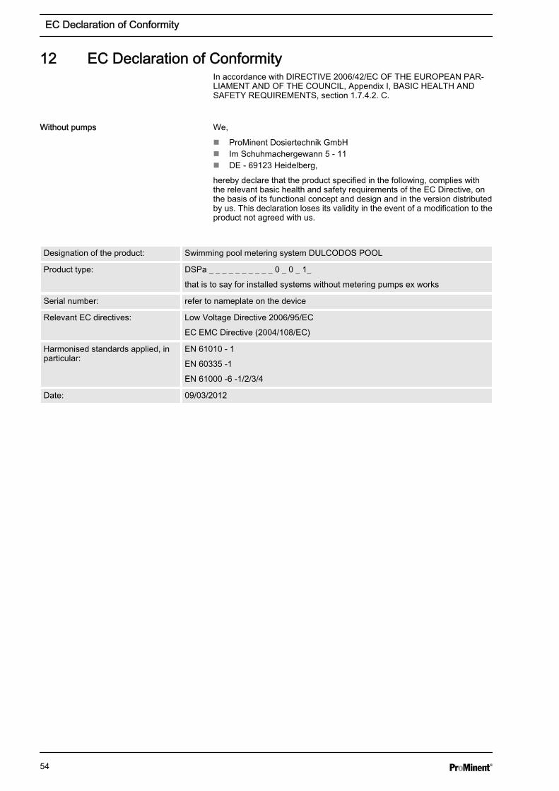
12 EC Declaration of ConformityIn accordance with DIRECTIVE 2006/42/EC OF THE EUROPEAN PAR‐LIAMENT AND OF THE COUNCIL, Appendix I, BASIC HEALTH ANDSAFETY REQUIREMENTS, section 1.7.4.2. C.
We,
n ProMinent Dosiertechnik GmbHn Im Schuhmachergewann 5 - 11n DE - 69123 Heidelberg,
hereby declare that the product specified in the following, complies withthe relevant basic health and safety requirements of the EC Directive, onthe basis of its functional concept and design and in the version distributedby us. This declaration loses its validity in the event of a modification to theproduct not agreed with us.
Designation of the product: Swimming pool metering system DULCODOS POOL
Product type: DSPa _ _ _ _ _ _ _ _ _ _ 0 _ 0 _ 1_
that is to say for installed systems without metering pumps ex works
Serial number: refer to nameplate on the device
Relevant EC directives: Low Voltage Directive 2006/95/EC
EC EMC Directive (2004/108/EC)
Harmonised standards applied, inparticular:
EN 61010 - 1
EN 60335 -1
EN 61000 -6 -1/2/3/4
Date: 09/03/2012
Without pumps
EC Declaration of Conformity
54
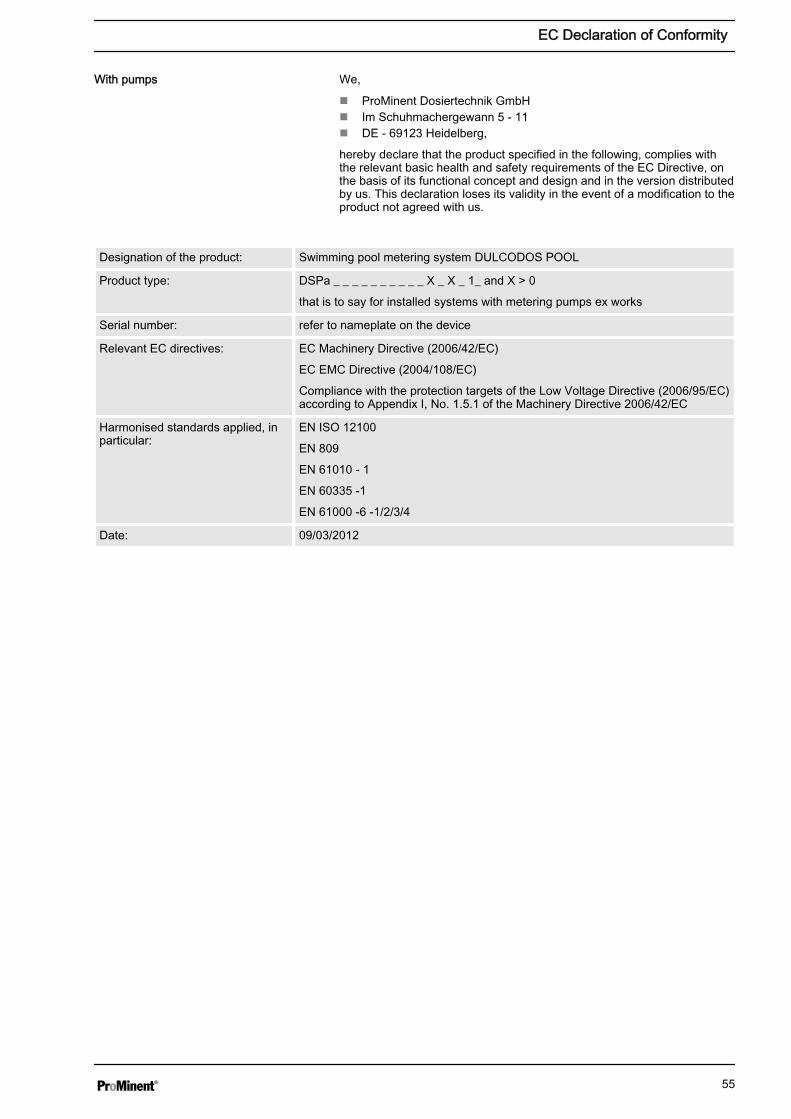
We,
n ProMinent Dosiertechnik GmbHn Im Schuhmachergewann 5 - 11n DE - 69123 Heidelberg,
hereby declare that the product specified in the following, complies withthe relevant basic health and safety requirements of the EC Directive, onthe basis of its functional concept and design and in the version distributedby us. This declaration loses its validity in the event of a modification to theproduct not agreed with us.
Designation of the product: Swimming pool metering system DULCODOS POOL
Product type: DSPa _ _ _ _ _ _ _ _ _ _ X _ X _ 1_ and X > 0
that is to say for installed systems with metering pumps ex works
Serial number: refer to nameplate on the device
Relevant EC directives: EC Machinery Directive (2006/42/EC)
EC EMC Directive (2004/108/EC)
Compliance with the protection targets of the Low Voltage Directive (2006/95/EC)according to Appendix I, No. 1.5.1 of the Machinery Directive 2006/42/EC
Harmonised standards applied, inparticular:
EN ISO 12100
EN 809
EN 61010 - 1
EN 60335 -1
EN 61000 -6 -1/2/3/4
Date: 09/03/2012
With pumps
EC Declaration of Conformity
55

13 IndexAAction, step by step . . . . . . . . . . . . . . . . . . . . . . . . . 2Ambient conditions . . . . . . . . . . . . . . . . . . . . . . . . . 16Applied harmonised standards . . . . . . . . . . . . . . 54, 55
BBuffer detection . . . . . . . . . . . . . . . . . . . . . . . . . . . 43Buffer solution . . . . . . . . . . . . . . . . . . . . . . . . . 42, 43
CChemical storage tanks . . . . . . . . . . . . . . . . . . . . . . 46
DDesignation of the product . . . . . . . . . . . . . . . . . 54, 55Displays . . . . . . . . . . . . . . . . . . . . . . . . . . . . . . . . 15
EEquipotential bonding pin . . . . . . . . . . . . . . . . . . . . 42
FF4 (CAL1Pt) . . . . . . . . . . . . . . . . . . . . . . . . . . . . . 42
GGeneral non-discriminatory approach . . . . . . . . . . . . . 2
KKeys . . . . . . . . . . . . . . . . . . . . . . . . . . . . . . . . . . . 14
LLinks to elements or sections of these instructions orother applicable documents . . . . . . . . . . . . . . . . . . . . 2
MMore symbols . . . . . . . . . . . . . . . . . . . . . . . . . . . . . 2
NNon-discriminatory approach . . . . . . . . . . . . . . . . . . . 2
QQuestion: How and why should I calibrate theproduct? . . . . . . . . . . . . . . . . . . . . . . . . . . . . . . . . 29Question: How can I store and transport the product? 16Question: How do I calibrate the chlorine sensor? . . . . 29Question: How do I calibrate the pH sensor? . . . . . . . 40Question: How do I eliminate functional faults? . . . . . . 46Question: How do I test the ORP sensor? . . . . . . . . . 39Question: How is the product hydraulically connectedand what connection versions are available? . . . . . . . 19Question: What ambient conditions need to be takeninto consideration? . . . . . . . . . . . . . . . . . . . . . . . . . 16Question: What components does the product include? 7Question: What do I have to consider when replacingthe chemical storage tanks? . . . . . . . . . . . . . . . . . . . 46
Question: What do I need to consider when operatingthe product for the first time? . . . . . . . . . . . . . . . . . . 26Question: What is the actual purpose of this product? . . 7Question: What should I consider when mounting theproduct on the wall? . . . . . . . . . . . . . . . . . . . . . . . . 17Question: What type of buffer solutions do I need? 39, 40
RRelevant EC directives . . . . . . . . . . . . . . . . . . . . 54, 55
SSafety information . . . . . . . . . . . . . . . . . . . . . . . . . 10Serial number . . . . . . . . . . . . . . . . . . . . . . . . . . 54, 55Storage . . . . . . . . . . . . . . . . . . . . . . . . . . . . . . . . . 16
TTransport . . . . . . . . . . . . . . . . . . . . . . . . . . . . . . . 16
UUsers' qualifications . . . . . . . . . . . . . . . . . . . . . . . . 10
Index
56

57

58

59

984156, 2, en_GB
© 2015
ProMinent GmbHIm Schuhmachergewann 5 - 1169123 Heidelberg, GermanyTelephone: +49 6221 842-0Fax: +49 6221 842-419Email: [email protected]: www.prominent.com