Ductile versus brittle behaviour of...
25
Reprlmed from PHILOSOPHICAL MAGAZINe, Vol. 29, No. I, p. 73, January 1974 Ductile versus brittle behaviour of crystalst By JAMES R. RICE Brown University, Providence, Rhode Island 02912, U.s:A. and ROBB THOMSON National Bureau of Standards, Washington, D.C. 20234, U.S.A. [Received 21 May 1973, and after revision 13 September 1973] ABSTRACT A necessary criterion for brittle fro.oture in crystals is established in terms of tho spontaneous emission of dislocations from nn o.tomioally sho.rp cleavage oraok. Wf' have calculated the etability of o. sharp crack against emission of a. blunting dislocation for a number of orystale and cwysto.l typos in two dimensions and the energy to form a stable loop of . .llr!lolc ,. tip in tht•ee dimensioM. We find tlio.t co:rltrat•y to previous expeot.ations, an atomically sharp cleavage crack is sta.blo in n wide range of crystal typBs, but. that in tho face centred onbic moto.Je investigated, blunting reactions ocour 11ponteneously. Of the body centred metals invettigated, iron ie an intermediate case between tho bL•ittle a.n<l ductile cases, o.nd tho ionic and covalent crystals investigated aro 1111 stable 11ga.inet disloou.tion emission. Quo.lito.tivoly, we find that crystals whose dislocations have wide cores, and email values of tho parametar f!b/y (p.bjy;S7·5 to 10) are ductile while crystals with no.rrow ooros o.nd largo vo.luos of pb/y are brittle. § 1. INTRODUCTION This paper is concerned with the problem of the ductile versus brittle response of crystals. There is in the literature of this subject a conventional understanding that a solid wiii either be ductile or truly brittle depending upon the ratio of theoretical shear strength to theoretical tensile strength (Kelly 1966). We believe that a conect description of this competition should include actual dislocation processes at cracks, since the ductile response of the solid must produce dislocations in order to yield. A truly ductile material like pure copper apparently cannot sustain a cleavage craolc, but may fail by plastic instability and necking on a gl'oss scale. Stronger materials apparently also exhibit the same essentially pla .stic necking phenomenon on a more microscopic scale through the proceaa of hole growth, although the macroscopic u.ppeu.rance of the failure t ThiR paper has been 1>repare<l nn<lel' initial 1mpport of tho ARPA MnterialB Research Council, with subsequont support; from AEC contracts at Brown University and SUNY/Stony Brook, and from the NBS.
Transcript of Ductile versus brittle behaviour of...

Reprlmed from PHILOSOPHICAL MAGAZINe, Vol. 29, No. I, p. 73, January 1974
Ductile versus brittle behaviour of crystalst
By JAMES R. RICE
Brown University, Providence, Rhode Island 02912, U.s:A.
and ROBB THOMSON National Bureau of Standards, Washington, D.C. 20234, U.S.A.
[Received 21 May 1973, and after revision 13 September 1973]
ABSTRACT
A necessary criterion for brittle fro.oture in crystals is established in terms of tho spontaneous emission of dislocations from nn o.tomioally sho.rp cleavage oraok. Wf' have calculated the etability of o. sharp crack against emission of a. blunting dislocation for a number of orystale and cwysto.l typos in two dimensions and the energy to form a stable loop of dif!ls>~tiQU.ftom.the . .llr!lolc , . tip in tht•ee dimensioM. We find tlio.t co:rltrat•y to previous expeot.ations, an atomically sharp cleavage crack is sta.blo in n wide range of crystal typBs, but. that in tho face centred onbic moto.Je investigated, blunting reactions ocour 11ponteneously. Of the body centred metals invettigated, iron ie an intermediate case between tho bL•ittle a.n<l ductile cases, o.nd tho ionic and covalent crystals investigated aro 1111 stable 11ga.inet disloou.tion emission. Quo.lito.tivoly, we find that crystals whose dislocations have wide cores, and email values of tho parametar f!b/y (p.bjy;S7·5 to 10) are ductile while crystals with no.rrow ooros o.nd largo vo.luos of pb/y are brittle.
§ 1. INTRODUCTION
This paper is concerned with the problem of the ductile versus brittle response of crystals. There is in the literature of this subject a conventional understanding that a solid wiii either be ductile or truly brittle depending upon the ratio of theoretical shear strength to theoretical tensile strength (Kelly 1966). We believe that a conect description of this competition should include actual dislocation processes at cracks, since the ductile response of the solid must produce dislocations in order to yield.
A truly ductile material like pure copper apparently cannot sustain a cleavage craolc, but may fail by plastic instability and necking on a gl'oss scale. Stronger materials apparently also exhibit the same essentially pla.stic necking phenomenon on a more microscopic scale through the proceaa of hole growth, although the macroscopic u.ppeu.rance of the failure
t ThiR paper has been 1>repare<l nn<lel' initial 1mpport of tho ARPA MnterialB Research Council, with subsequont support; from AEC contracts at Brown University and SUNY/Stony Brook, and from the NBS.

74 J. R. Rice and R. 'l'homaon on the
is crack -like. On the opposite end of the scale, some materials like diamond and mica apparently ca.n undergo pure brittle cleavage with no discoverable plasticity associated with the process. In between these two extremes, the1·e apparently exists a class of materials where a cleavage crack in the true atomically sharp sense exists, but is surrounded o.nd a.esociated with an atmosphere of dislocations. (Burns and Webb 1970, Burns 1970}. This intermediate case exhibits many complexities, such as high effective surface energies, plastic zones surrounding the crack tip, etc., but there is no reason to suppose that, provided hole growth is not occurring, the crack tip is not sharp on the atomic leveL Of course, experimental proof of this statement in any given case will be indirect at best, but the theoretical descriptions of cleavage and of hole growth are sufficiently different as to make one wish to distinguish as clearly as possible bet,veen the sepa1·ate physical cases.
Kelly, Tyson and Cottrell (1967) were the first to pose this problem of brittle versus ductile fractm·e in an essentially proper way when they attempted to tes~ t he self-consistency of t he proposition that a cleavage crack can exist ih a particular type of crystal. They, in effect, asked : " If a cleavage crack were created by some process in a crystal, would the tip spontaneously blunt as the result of sheat· by the atoms of the tip region 1" They then postulated that such would be the case if the highest shear stress in the vicinity of the crack exceeded the theoretical shear strength of the material. However, this criterion cannot be sufficient for the crack to blunt, because the shear stress near a crack is not everywhere constant on the shea.r plane as it would have to be to cause the atoms to shear past one another uniformly. Instead, the stress is highly localized in the vicinity of the crock tip. By geometrical necessity,localized shear on a plane intersecting the crack tip caused by the high shear stresses there, matched to a non -sheared region at greater distances on the same plane, where the stress is below the theoretical strength simply defines a dislocation. Hence, a blunting reaction at the crack tip requires the production (or annihilation) of dislocations.
Of course it is recognized that a complete resolution of this problem must rely on a discrete lattice calculation involving realistic non-linear force fields. Calculations of this sort are extremely complex, and require accurate knowledge of atomic force fields over their entire range, but have been attempted for iron by Markworth, Kanninen and Gehlen (1973). These considerations enter the present work only indirectly insofar as they determine par1.1.meters sttch as dislocation core cut-off, surface energy, etc. With our method, however, it is possible to gain an overview of a wide class of materials.
Kelly, Tyson, and Cottrell indeed discussed one kind of dislocation renction for NnCI. They calculated the approximate energy to form a full metastable loop of dislocation nen.r the crack in NaCl, and found the ene1·gy to be prohibitively high. Others luwe also discussed dislocation formation near the crack tip (Armstrong 1960, Kitu.jima 1906).

Ductile ve1·sus brittle beh.aviou1· of c1'ystals 75
Armstrong has, in particular, estimated the formation energy of a dislocation dipole loop completely surrounding a circular crack in a crystal. However, this type of dislocation interaction does not correspond to a blunting reaction and does not directly addtess the question we pose.
In this paper, we shall propose models for the production of a dislocation from the tip of the crack in such a way tha.t after the dislocation expands under the external stress field as concentrated by the presence of the crack, an atomically sharp crack will have been blunted by one atomic plane (fig. 1). This blunted crack will then be trapped at the original lattice position until the external stress is increased substantially (when
18· 1
~t ,.., ~,..,~ ,.,...,...,...,-1 ,..r-1-1~~
r"'1" ...... ~""' ~~ ,_...v-""
F'
~ ............ ~ ...... ~~ ...... V" ~'""" .... ..., ~--~ v""
H-"r-r- vi' ~""
1- ...., r-r- ~ 1-r-.r-N:-- 'r--h
.............. r-. r-. I'- r-- .... 't-., t--r-. 'I r---._._._._I' t'-- Nr--.~
o........._l' ~'-r--- Ni'-........... t--r---~f't--
(a) ................ t!--....
An atomically sharp crack iR blunted when l~ dialoco.tioll is emittell from the till when the Burger11 vector has a normal component to the fraotm·e plane.

76 J. R. Rice and R. Thomson on the
probably furthet· dislocation blunting may be possible). Crystals for which dislocation emission is spontaneous can be expected to be good candidates for essentially plastic opening of the crack. Crystals for which there exists a large energy barrier for this emission can be expected to be good candidates for brittle cleavage (but perhaps where the crack has associated with it clouds of dislocations which are formed or captured through other processes in the nearby lattice). In order for a dislocation to blunt a crack, it is necessary for the Burgers vector to have a component normal to the crack plane, and for the slip plane to intersect the crack line (or crack front) along its whole length, i.e. the crack line must be contained within the slip plane.
It is, of course, possible to conceive of a process by which the crack may be blunted by dislocations which are formed from nearby sources and which are emitted on precisely the right plane to blunt the crack tip. In view of the fact that the stress field in a region surrounding a cleavage crack will be above the macroscopic plastic flow stress fm· the material, one might suppose this could be an effective blunting mechanism. However, ma.croscopic yield is a property nssociated only with regions of the size of many microns, even for fairly ductile materials. Hence, for a mndom position of the crack tip, the probability of finding a source on the correct plane at a distance from the crack for which the source can operate is small.
The plan of the paper is as follows. In the next section, we shall consider the va.rio·us forces operating between a crack and a dislocation in two dimensions. These forces are (1) the force on a dislocation due to the stress field surrounding the crack, (2) the surface tension force caused by creating more surface at the blunted crock, and (3) the image force of the dislocation in the free surface of the crack. The fit·st term repels the dislocation, and the latter two attract it toward the crack tip, giving rise to the possibility of a position of unstable equilibrium. In§ 3 we estimate the activation energy for formation of a dislocation half loop out of the crack under the action of these forces when an energy barrier exists. Finally, in§ 4 we discuss the physioa.l consequences of our calculations.
§ 2. fORCES ON A DISLOCATION NEAR A CRACK TIP
Let us suppose that the loads on the body considered n,ct symmetrically about the plane of a. straight crack, so that before emission of the dislocation, only the tensile opening mode of reln,tive crack surface displacement is present. If !( 1 is the ' elastic stress intensity factor ' (see, for example, Rice 1968) due to the loads, then in two dimensions the in-plane shear stress acting at distance p on the slip pln.ne of fig. 2 is
a t>.J> = ]( r{ 8rrp )-1/2 sin if> cos if>/2. ( l)
For this equation to be valid, p must be a small fraction of overall crack length. The anti-plane shear stt·ess component (i.e. in the direction of

Ductile vet· sus bl'ittle behaviour of ct·ystals 77
b8
) is zero. 'l'hc release of potential energy of the body and load system per unit of new c1·n.ck at•ea is
(2)
(E =Young's modulus, v =Poisson's ratio.) At the fl·acture load predicted on the Griffith theory, G = 2y where y is the true surface energy of the cmck plane. Thus, if the applied loa.d on the body is chosen as that which would cause fracture if no dislocations were emitted, then the force (shear stress times Burgers vector) on the dislocation segment shown in fig. 2 due to the applied load is
[ Eyb ]112
f a= (7~bc= ( 2.' sin if> cos ~/2 cos 1/J. 4711 - v) (3)
Here~= pfb and b0 =b cos rp is the edge component. 'fhe screw component b
8 does not appear since the applied load induces no shear ·stress in this
direction.
Fig.2
ORAOJt LIMB
Geometry of the dislocation, crack configuration in two dimensions. b0 and b, are perpendicula.r a.nd parallel components of the Burgers vector relative to the crack.
There will be an ' image ' force which tends to pull the dislocation bacl{ into the crack. This may be inferred from direct solution of the corresponding ela.sticity problem, as presented in most general form by Atldnson (1966} fot· anisotropic materials. A rather different derivation is presented in the Appendix, for a straight dislocation parallel to the crack tip in an isotropic material. (The procedure of the Appendix is based on energy considerations and properties of point functions, rather than on direct solution of the elastic field equations for a. dislocation near a crack. The

78 J. R. Rice and R. Thomson on the
a.ppron.ch is 1·endily genera.lizecl to other elnstic interaction problems, and may be of some interest in itself.) 1'he resulting image force (eqn. Al4) is
(4)
This is a remarkable result, because precisely the same expression for the image force is obtained in the case of a. dislocation in a. half spa.ce with its core lying parallel to, and at perpendicular distance p from, the free surface (see, for example, Hirth and Lathe 1968). Both of the above forces are calculated on the assumptions of 'infinitesimal ' elasticity, and actual geometry changes at the crack tip due to emission of the dislocation have been neglected. The image force term may be rewritten from fig. 2 as
I I - - Eb ( 1 - v sin2 tP)
- 811(1- v2}e ' (5}
f=pfb. In fig. I, as the dislocation is formed, a ledge is left behind, and as the
core comes through the surface, forces due to the formation of the ledge must be included. As a function of the position, [=p/b, of the dislocation, the ledge energy is given by
V 2 ,/, . ,1, -1 2[ l = - yb cos "f sm "f tan 312 t . ~ e ~o
(6)
In deriving (6), we have used the misfit function for a Peierls model of the dislocation with a width 01' core cut off eo. which is consistent with the quantity r0fb where 1·0 is defined by Hirth a.nd Lothe (1968), p. 212. The sin q, dependence is taken t o approximately represent the modification of ledge energy from yb0 due to slip plane inclination. The force is consequently
2 ycx cos .P sin rp /t = -- where ex= e3
'2 t0f2.
~ gs +a2
Note that the g-• and g-2 attra~tion back toward crack, due to the image and ledge forces, outweighs the g-m force resulting from the applied load when e is small, whereas just the opposite happens when e is large. Hence, the equilibrium position of the dislocation is ·unstable, and the dislocation will be driven away indefinitely, until it reaches some obstacle, if it ever attains a distance from the crack tip greater than the equilibrium dista.nce.
The critical distance, ec at which a. straight dislocation is in unstable equilibrium under these three forces is, from (3), (5), and (6), given by the solution of
[ 1 1 - v sin 2 if! 2 ex I ( 1 ) 1/2]
ftot=P,b - 41Te 1-v - 1T'TJ'f3' es+ct2 + TJfJ 271(1-v)e ""0
' (7
)

Duc,tile ve1·BUS brittle behavicnu· of ct·ystals
We have uaed the following abbreviations,
~ =cos t/J sin rp cos rp/2,
~~ = cos rfo sin rp,
7J2=p.bfy,
79
(8)
where 1L is the shear modulus, If the value of eo is leas than the core cut-off, we presumably have a caae where the method does not apply, and spontaneous generation is a good possibility. Equations (3) and (5) diverge for e-+o, but, of CO\trse, the forces they represent must actually in toto approach zero as ~-+0 because of non-linear core effects.
We display in table 1 the relevant physical data with the values we have chosen. The values of y contain the greatest degree of uncertainty, and we discuss the problems associated with surface energy for ou1· calculation in§ 4. Table 2 displays the results of the solution of eqn (7) for the various solids, together with suggested values from Hirth and Lothe (1968) for the elastic cut-off for comparison. We also list some cruder estimates of the critical distance, ec' and eoN. In eo'' we neglect the effect of the ledge in eqn. (7), and then the condition is given by
(9)
In the second estimate, we average over the geometrical and crystallographic effects still}Jresent in (9), giving an even cruder estimate,
(: n"' p.b §.o -lOy · (10)
It is interesting to enquire how splitting the dislocation will affect the calculations, since certainly in the face centred metals, splitting does ocout·. In this case, the Burgers vector will be lowered in magnitude, and the angle, t/J, will be changed. So far as the size of the Burgers vector is concerned, eqn. (7) is dimensionless, and is not affected. The size of the cutoff is sensitive to b, however, and in fact the value we have chosen is just that appropriate to the split dislocation in the face centred metals. Equation (7) does contain the crystallography of the Burgers vector through the angle, t/J, however, in a rather complicated manner. For the whole dislocation, rfo = 30°, and there are two possibilities for the two partials, rfo=0° and~= 60°. For the first value, the ratio of the various terms in eqn. (7) is only chan~ about 5% from their values for t he whole dislocation, thuBlea.ving the results of table 2 unchanged. For the second case, where rfo=60°, the first term in eqn. (7) becomes about 50% larger than for the whole dislocation, thereby increasing the value of ec· We show a few values for this partial in table 2.

Cry
stal
C
leav
age
syst
em
Fac
e ce
ntre
d m
etal
s P
b
(001
) A
u [1
10]
Cu
A
g A
l N
i
Bo
dy
ce
ntre
d m
etal
s N
a (0
01)
Fe
(100
) w
Fe
* (0
01 )/
[1 IO
]
Ioni
c L
iF
(001
) N
aCJ
[100
]
MgO
~03
(101
2)/[
1210
)
Dia
mo
nd
cu
bic
Si
(11
1)
Ge
[Oil
) c H
exag
onal
m
etal
s B
e (0
00
1)
Zn
[000
1]
---
Tab
le l
. P
hysi
cal p
aram
eter
s o
f cr
ysta
ls
Sli
p y
!J-X
l01
1
syst
-em
cg
s cg
s
(H1
) 44
0 (l
) 0·
727
[lO
T]
1418
(2)
2·
37
1688
(2)
4·
05
1135
(2)
2·
56
840
(1)
2·51
17
25 (
3)
7·4
8
(Oil
) 23
7 (1
) 0·
243
[111
] 19
75 (
4)
6·92
1
70
0(5
) 16
·0
(11
0)/
[Ill
] 19
75 (
4)
6·92
(Oil
) 48
0 (6
) 4·
40
[011
] 25
0 (7
) 1·
63
(115
) (8
) 1·
63
1200
(9)
11
·57
(000
I )/[
IT20
] 60
00 (
10)
23·3
(Ill
) 12
00 (
4)
6·05
[IT
O]
600
{1}
4·92
54
00 (1
2}
50·9
(ijk
O)
1620
(1)
15
·5
[000
1]
575
{9)
3·83
----
~~
v b
Ang
stro
ms
0·38
7 3·
49
0·41
2 2·
87
0·32
4 2·
55
0·35
4 2·
88
0·34
7 2·
85
0·27
6 2·
49
0·20
1 3·
66
0·29
1 2-
49
0·27
8 2·
74:
0·29
1 2·
49
0·18
7 2·
848
0·24
8 3·
988
0·24
8 3·
988
0·17
3 2·
974
0·20
0 4·
75
0·21
5 3·
38
0·20
0 4·
00
0·06
8 2·
52
0·33
3 3·
58
0·33
3 4·
94
~= J(
~:)
2·40
1 2·
190
2·47
3 2·
549
2·91
8 3·
286
1·93
7 2·
954
5·07
8 2·
954
5·10
9 5·
099
(7 ·5
18)
5·35
5 4·
295
4·39
4 5·
727
4·S
74
5·84
9 5·
736
I
ao
0 ~
~
~
(':>
(!) ~ ~ ~
::r
0 3 (IJ
0 ;::1 ~ -;_::,-. <'>

Crystal
Pb Au Cu Ag AI Ni
Na Fe w Fe•
LiF
NaCI
MgO A120 3
Si Ge c
Be Zn
Ductile ve1·sus b1'ittle behaviou?' of crystals
Table 2. Two-dimen1:1ional results
Core Critical Approximate cut-off distance values
~0 e. 'c' fen~
wfo ledge p.hflOy
2 H 0·88 0·58 2 0·8tl 0·65 0·48 2 1·00 0·77 0·61 2 1·09 0·85 0·65 2 1·4 H 0·815 2 1·7 1·3 1·08
2/3 1·2 0·54 0·375 2/3 1·9 1·3 0·87 2/3 4·0 3·9 2·6 2/3 2·7 I·9 0·87
0·25 3·2 2·9 2·6 { 0·25} { 3·4} { 3·2} { 2·6}
(0·25) {7·0) (7·0) (5·6) 0·25 3·4 3·2 2·9 0·25 2·3 2·1 1·8
0·25 2·2 2·0 1·9 0·25 3·7 3·3 3·3 0·25 2-4 2·2 2·4
2/3 4·5 4·1 3·4 2/3 4·3 3·9 3·3
Partial dislocations b = v~IZ) [2IT], .p =60°
Cu
I 2
I 1·4 0·91 0·35
Ni 2 2·3 1·6 0·62
§ 3. ENERGY CONSIDERATIONS
81
If the equilibrium point, ~c• is larger than the core cut-off, then there is a.n energy hump for the dislocation to jump in order to be emitted from the crack. Clearly, in this ca.se, it will be impossible for a uniform straight line to be emitted from the crack, because for an infinite length of dislocation, the energy diverges. Instead, a. local fluctuation in the form of an irregular loop will be formed which, beyond the saddle point configuration, will expand under the external stress. The factors determining the saddle point configuration are the BEnne as before. Image and ledge forces will predominate for small loop sizes, while for larger ones the external st.ress is dominant.

82 J. R. Rice and R. Thomson on the
In the elastic three-dimensionn.l!Jl'Oblem, even in the isotropic regime, the problem of determining the saddle point configuration and consequently its energy is intractable in part because the fo1·ce fields are variable, and in part because rigorous treatments of three-dimensional dislocation problems are not possible when the shape is complicated. In fact, although we know the image force for a straight dislocation parallel to the crack, image terms are known to be complex when the shape is more complicated, even without the additional complexity of the crack half surface. We shall thus proceed by developing some qualitative insights into the problem, and then make some simplifying assumptions about the saddle point configuration which allow us to make meaningful calculations.
First, the stress field due to the applied load is straightfonvard, and yields a normal force, f a• on a dislocation element, dl, given by the local value of the stress, a. This force is
f,=(a·b)xdl. (11)
The ledge force is always a minor term, except possibly very near the oracle surface. It will have the primary effect of drawing togethe1· the two ends of the loop where they touch the crack surface. It will act just like a pure surface tension on these ends because of the surface energy required to expose the ledge as the loop expands.
The image force, as mentioned above, is more complex. In pt·oblems of dislocations interacting with normal surfaces, it is a useful first approximation to simply replace the image terms by the action of an image dislocation reflected in the surface. This replacement is not normally rigorous, but yields a fair approximation. Since in our case of the ora{}k, the straight dislocation yields the same result a·S for a normal surface, we shall adopt this simple stratagem for the crack. This means that in order to calculate the energy of a dislocation half loop configuration which ends at the crack surface, we need do no more than calculate the energy of aj1tll loop including the reflected image, and take half of the result. This energy will then include the image terms.
One further very important result follows from the presence of the image term. The image term requires that when a dislocation approaches an open surface, it must out the surface at normal incidence. The predominance of the image term in the immediate vicinity of the crack surface will require the same boundary condition on the dislocation at the crack surface. This condition, in conjunction with the magnitude of the stress in the region beyond ec are the crucial determinants of the total activation energy.
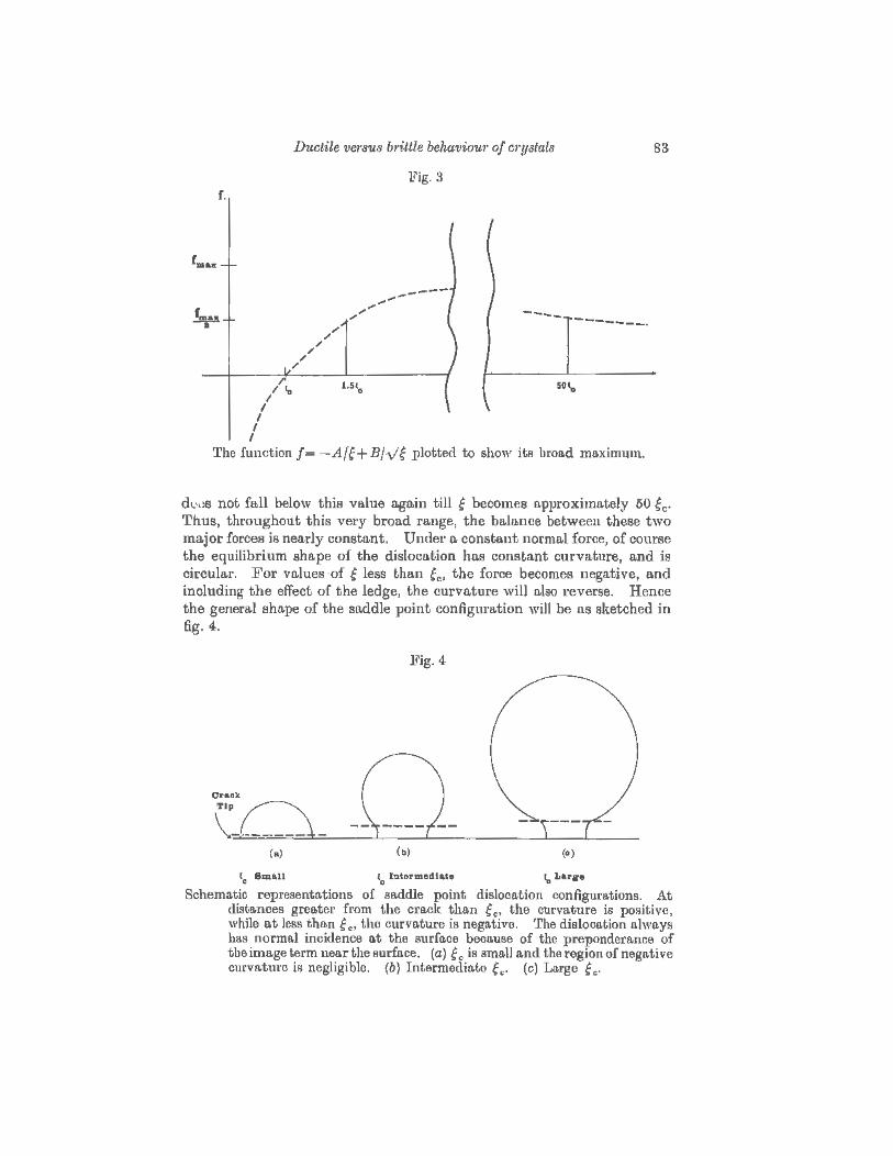
We note one final qualitative ohat·acteristic of the two dimensional force field which is very suggestive for our three-dimensional treatment. Except for the ledge term in eqn. (7}, which is important only very near the crack tip, the net force is the difference between 1/e and 1/ve. a very broad function which we have plotted in fig. 3. The point at which this function reaches one half its maximum value is about 1·5 ec, and it
r.
r .....
k •
I'
/"' I
I I
I
Ductile versus bt·ittle behaviou1· of C1'!J8lals
Fig. 3
---- -------·
The function f = -A{g+Bfv~ plotted to show its broad maximum.
83
d~.,.~s not fall below this value again till ~ becomes approximately 50 ~c· Thus, throughout this very broad range, the balance between these two major forces is nearly constant. Under a constant normal force, of course the equilibrium shape of the dislocation has constant curvature, and is circula.r. For values ·of e leas than ~e• the force becomes negative, and including the effect of the ledge, the curvature will also reverse. Hence the general shape of the saddle point confignra.tion will be a.s sketched in fig. 4.
l?ig. 4
l0
Slll•ll (0
btermedt•t• 1, Lar~re
Schematic representations of saddle point dislocation configurations. At distances greater from the crack than e •. the curvature is positive , while at less tho.n g c• the curvature is negative. 'rhe dislocation always has normal incidence at the surface becGuse of the preponderance of the image term nea.r the surface. (a) f c is small and the region of negative ourvatul'c iii negligible. {b) Intermediate ~c· (c) Large ~ c·

84 J . R. Rice and R. Thomson on the
In view of these qualitative background comments, we feel justified in proceeding with the assumption that the approximate equilibrium shape is the simple half circle depicted in fig. 4 (a). In view of the broad maximum in the effective force field, we believe the energy of the activated state thus computed is a reasonable estimate of the true energy, and our use of the circular shape probably introduces no major errors in the calculation.
We thus calculate the total energy of the activated state of the system, which consists of three parts. (1) The self energy of the dislocation half loop. As mentioned before, this energy will automatically include the image term contribution. (2) The energy of the ledge. (3) The energy gained by the dislocation loop as it expands under the influence of the stress surrounding the crack. In order to determine the size of the loop of the activated state, we locate the maximum energy of the loop as a function of the loop radius.
The self energy of a dislocation half loop as given by Hirth and Lothe (1968) is
- 3. . 2- jl 81' Uscu-11-b 1 8(1- ")In e2.eo· (12)
In this equation, i' and eo are respectively the radii of the half circle and radii of the core cut-off in units of the Burgers vector, b. so is the same quantity as used for the core cut-off in§ 2.
To the self enet·gy must be added the energy of the ledge formed as the loop expands. We write this in the form
(13)
Equation (13) simplifies the expression for a ledge as we used it in § 2. Here we assume that when the radius ,. is gl'ea.ter than the cut-off radius, the ledge is fuHy formed, and that the energy is linear in the radius of the loop.
Finally, we compute the energy gained by the half loop in the stress field of the crack tip. In terms of eqn. (3) and fig. 5, the energy to expand the loop from the initial radius, s0 • to 1' is
[ Eyb ] 112
•• ., 1· U,=- 4 (l 2) b2 cos!fsintfocostfo/2 Jd1· J. dB I( . 0 .
1T - v f, o ·\. 1' Sill )
Noting that
we then have
j do = 1T112 r( u 0 y(sin 8) r(t)
(l4)
(15)

Ductile versus b1'ittle behaviout· of ctystals 85
Fig.5
Configuration for calculating the work done under the crack stress by the expanding dislocation. The work integration has the lower limit shown when f =eo·
The total energy change for a crack which has emitted a dislocation loop is then
Uact. = f.J.b3 [ t·U0 In;~+ Ut(t·- eo)- iU a (,.st:L~0312) J , 2-v u - .,..,...,....____,.
o- 8(1- v)'
U t = 2 :b cos 1/J sin 4> ,
2·092 J(y) . Us= y'(l-v) f.J.b sm4>cosi/Jcos4>/2,
(8/e2 ~l). From {17), the condition for the activated state is
(17)
(18}
Schematically, the three terms in (17) are sketched in fig. 6. The stress term eventually always dominates the other two for large 1·, but depending upon the parameters, the self energy plus the ledge term may be dominant for values nea.· f 0 . That is to say, depending upon the parameters, there may be a spontaneous emission of a dislocation loop with no activation energy, or there may be a finite activation energy to form the loop whose radius is determined by eqn. {I 8).
We have solved eqn. (18) for the critical loop size, and calculated the activation energy for the list of materials given in tltble l. The t•esnlts are listed in table 3. Furthet·, the functional val'in.tion of the activation energy with )'/f.J.b, ~0, and orientation parameters is shown in fig. 7. In

86 J. R. Rice and R. Thomson on the
Fig. 6
u
Schematic variation of the three terms in cqn. ( 17) as a function of the radius.
Table 3. Three-dimensional results
Activation Radius of Crystal energy activated loop
(electron volts) (in units of b)
Ph Au Cu Ag AI Ni
Spontaneous emission- No activated state for r > eo·
Na. 0·02 1·5 Fe 2·2 5·1 w 329 50·7 Fe* 19 17
LiF 58 32
NaCl { {2!~)} {(~~)} MgO 205 37 AaO~ 852 20
Si Ill 20 Ge 260 4-2 c 351 27
Be 180 23 Zn 107 21·2

Ductile Ve1'8U8 m·itlle be/taVWU1' oj C1'Y8fUUJ 87
this plot, the activation energy (eqn. ( 17}) is plotted after r is eliminated th1·ough eqn. (18). Here it is convenient to plot the dimensionless energy
in terms of
Uact 1tact. = {2- v)2 f12 3
8(1- v) {1' 1-1-b
S = 16(1- v) .!. and 5{:J'{2-v) fLb
(19)
(20)
Indeed, these forms have been chosen because, for typical values of v and the orientation parameters, they reduce to
(21)
Fig. 7
••• ,,~
0.4
Dopendence of activation energy for dislocation nucleation on S (~ y/p.b), o.nd R0 ( ~ tol; exact definitiol1.8 of S and R0 , and normalization of energy o.re given in text.

88 J. R. Rice ltnd R. Thomson on tlbe
It is seen that the behaviour divides mainly into two ldnds: If the orientation-dependent core parameter, R0 , is small, there is a substantial energy barrier to disloco.tion nucleation for all values of yfp.b (i.e., Uaot ~ 0· 1 p.b3).
On the other hand, if R0 is large there will be an energy barrier only if the surface energy parameter, S, is smaller than that at which the curves cross the S axis; otherwise there is spontaneous nucleation. The curves for the larger values of R0 rise so steeply that there is essentially a critical value of S below which the energy barrier is substantial, and above which there is sponto.neous nucleation, although finer examination shows that there is a narrow range of R0 and S values fot· which Unct. is low enough that thermal activation could blunt the crack for sufficiently long time scales of load application.
§ 4. PHYSICAL RESUL'l'S AND INTERPRETATION
4.l. S·U1jace ene1·gy
Among tho experimentally determined values listed in table 1, the values of yare the ones for which the only important uncertainties exist.
For tungsten, Cordwell and Hull (1969) find that the surface energy varies from a low value of 1700 cgs at low temperature to 6000 cgs at higher temperature. The higher value apparently is due to plasticity induced in the vicinity of the moving crack. Other values have been measured by other workers intermediate to these extremes, but we believe the low value listed represents the bare crack.
N aCl is claimed by Class { 1964) in his thesis to have a surface energy of 115 cgs, and this value is adopted by Kelly ( 1966). On the other hand, we believe the value 250 is mot·e likely. It is in the range of the experiments of Gilman (1960), Wiederhorn, Voses and Bean (1970), and Benson and Benson (1955), Benson, Schreiber and Va.n Zeggeren (1956) and Benson and Balk (1959), and is in reasonable agreement with the theoretical calculations, which for this crystal should not have a large error (Tosi (1964), MacMillan and Kelly (1972)). We list both values, and 1·esults for both, however.
For A120 3, we have a range of values in the literature all the way from 1000 cgs as given by Kingery (1954) for the basal plane to 6000 cgs as determined in cleavage experiments on the rhombohedml planes by Wiederhorn (1969). Wiederhorn also reports that cleavage is not possible on the basal planes, and in a private communication has noted that the cleavage surface energy for these planes must in consequence be in excess of 40 000 cgs! One wonders if the value reported by Kingery (not measured in cleavage) is not actually either that for a restructured surface or a composite value for a dimpled surface whose average orientation is [0001 ], but not the true basal pln.ne. Consequently, we nse 'Y = 0000 cgs in our work.
In Zn, :Maitland and Chadwick (1969) have measured a rn-nge of values from 100 cgs (confirmed by other previous authors), to 575 cgs, depending

Ductile ve?'sus b1'ittle behaviou1· of C?'1}Btals 89
upon the technique used for making the measurement. Because of weaknesses in the analysis as applied to the experiments yielding the lower value, they believe the value of 575 cgs is to be preferred.
But experimental difficulties do not exhalJSt our problems with the surface energy. One must also be certain that the surface energy as measured experimentally and the surface energy as we use it are synony· mous. In our work, the con·ect y is derived as the energy necessary to break bonds at a crack tip. Even in a pure cleavage event where no dislocations are produced, this process may not correspond to the thermo· dynamic surface energy because of relaxation effects which are possible on some crystal surfaces, such as Si, where the surface is entirely restructured. For this reason, the value chosen for Si is del'ived in a cleavage expel'iment, and for diamond is calculated from the value of the ca.z·bon-carbon bond. Unfortunately no cleavage surface energies are available for Ge. We also note a fmther point of rigor. In crystals with high Peiel'is barriers where the discrete lattice force fields oon trap a crack (Hsieh and Thomson 1973) they measured to grow a crack is different from they measured to heal a crack.
4.2. Two-dimensional results
The results in table 3 suggest tho.t the fo.ce-centred m·ystn.ls, with the possible exception ofNi which has a borderline ec, nre unstable to dislocation formation, since the critical distance, ec. is less than the core radius, eo· Since all the elastic forces become impossible to define inside the core radius, and since the repulsive forces o,re dominant for o,ll distances larger than the core, we believe a crack in these crystals cannot sustain the large shear forces at its tip without forming the dislocation spontaneously. Nn., of the body-centred crystals, probably also spontaneously emits the dislocation because of the small size of fc, and also because we believe that in this case eo is not so small as 2/3, as is assumed for the other body-centred cubics. In all other oases, fc is sensibly larger than the core size, and we believe this gives rise to an energy hump which the dislocation must negotiate as it is formed.
We have listed in table 2 two other cruder estimates of gc· In the first, we neglect the ledge term and in the second average over the geome;try. Both are fair approximations to the more accurate values for the brittle materials in the lowe1' half of the ta.ble. The ledge term is seen to be important for the softer crystals, ~s one would expect.
The dimensionless ratio, p.bjy, related to our ~011 has a.lready entered
into Armstrong's (196G) discussion of the brittle versus ductile competition, and we see that it is indeed explicit in our own work. However, in o\lr theory, as one progresses down the list of crystnls in to,ble 2, it is the opposite tendency of the gt·owing value of p.bfy n.nd the decreasing vttluc of the core cut-off which ma]ces the difference between the ductile facecentred cubics and the more brittle body-centred cubics.

90 J. R. Rice and R. 'l'homson on the
We note in table 2 the positions of iron and nickel between the obviously ductile and obviously brittle solids. We give two calculations for iron. In one, the cra.ck line runs along a cube direction, [100], and in the second, the crack line runs along [110]. The second is actually that observed by Tetelman and Robertson (1963) in silicon iron, but it is the former which has the interesting low value of fc·
We have listed the results for a split dislocation for a noble metal and for nickel. (Aluminium has small or no splitting.) The results shown are for only one of the partials. In the case shown, the pa1·tial has unfavourable geometrical factors, since it is not oriented to cause the cra,ck to open effectively. In this unfavorable case, the critical radii are slightly increased, but not enough to change our general results.
4.3. TJt,·ee-dimensional 1·es~tlts
'fhe three-dimensional results fot· the estimated activation energy a.s given in table 3 confirm the two-dimensional findings. We find a negative activation energy for the face-centred cubics, which again means that since all energies are cut off at the core radius, by the time any dislocation is well formed, it is under the primary influence of the repulsive forces. Again, Na would seem to have an essentially spontaneous emission, not only because of the small value of the calculated activation energy, but also because we have probably underestimated the true dislocation core size of this very soft crystal.
The main surprise when comparing the two- with the three -dimensional results is the very large values obtained fo1· the a.ctivation energy of the brittle crystals, even though ~c is usua,lly a smn.U number. One might suppose that it would take only a small energy to push a local segment of dislocation past gc, say in NaCI, over a small front of the crack tip, a,nd that the repulsive force would then be able to dominate the picture sufficiently to expand the fluctuation indefinitely. However, the reason this is not so is that the dislocation must meet the crack surface at normal incidence. Otherwise, the forces there will coHapse the fluctuation no matter what happens to that portion lying over the hump beyond ec· In order for the dislocation to meet the sm·face perpendicularly, a full half loop of dislocation must be formed in the region of 1•epulsive forces, which is costly in dislocation line energy.
4. 4. Conoluaions We find a vet·y strong tendency for crystals to be either completely
ductile, or completely bt•ittle, so far as dislocation emission is concerned. Iron and nickel are the only interesting cases where our calculations suggest that the activation energy ma,y be sufficiently low that thermal fluctuations could play a role. With the various uncertainties in our calculations,

Ductile ve?'SU3 b1·ittle behavio1u· of c1·ystals 91
we are unfortunately not able to pin down the vnluea in these cases sufficiently to make a. definite prediction.
Except for iron, sodium, and the face-centred cubics we feel confident in predicting that no spontaneous or thermally assisted blunting of a crack tip can occur in the other crystals investigated. Even with the uncertainties in the y and the other approximations made, crystals like Li]_{, and NaCl (to say nothing of the hexagonal metals) seem immune enough to this process. This conclusion means that if blunting does occur it must be because of dislocations produced outside the tip region, and which are then attracted toward, and collide with it.
Our conclusions are at vat·iance with the often quoted claim that cl'aclts cu.nnot remain sharp (and the crystals thus be brittle} if the shear stress at the crack tip is larger than thG theoretical shear stress of the homogeneous crystal. As we stated in the introduction, a. shear stress at the value of the the01·etica.J shear strength will cause the crystal to break down only if the stress is homogeneously applied across an entire plane running through the crystal. If the stress is only appled locally on that plane, then atoms where the stress has dropped below the maximum value will not be displaced from their lattice positions, and atoms where the force is maximum will not necessarily be displaced even though the stress is o.bove the theoretical shear strength because of the resistance offered by atoms in the undeformed region of the plane.
Our conclusions suggest that so far as spontaneous emission is concerned, atomically sharp cleavage cracks are by no means a minority occurrence in materials. When the condition p.bfy > 7·5-1 0 is approximately satisfied, we have reason to expect the crack to remain sharp, th01.1gh geometrical factors and variations in core size make this condition only approximate. This condition, in the cases investigated, is satisfied for all but the facecentred cubic metals, and certain borderline body-centred metals.
Our conclusions leave the precise morphology of cleavage cracks ulti mately undetermined, however, because they do not address blunting rea.ctions due to dislocations which might be attracted to the crack tip from the surrounding crystal. Processes which lower the cleavability by increasing the effective cleavage surface energy through the action of dislocation atmospherea trapped by the stress field of the crack are also not addressed here. On the other hand, our work does allow an evaluatiOJ;t of environment11l effects which can be understood in terms of a lowering of y. By increasing the ratio p.b/y, these could presumably make possible atomically sharp cracking, even in solids such n.s f.c.c. crystals which normally show ductile response. Then the ' cleavage ' is not necessarily fast-running, but can proceed only 116 fast as reactions take place to bring about the requisite lowering of y at the tip. It is possible that some environmentally assisted crack growth can be understood in this way.

92 J. R. Rice and R. Thomson o-n tke
APPENDIX
I mage force o1~ dislocation near a c~·ack tip To compute the image force, consider fig. 8 in which astl·aight dislocation
line lies parallel to a crack front, with the slip plane intersecting the ft·acture plane at distance a: ahead of the tip. We are ultimately interested in the case a:= 0, but by considering a: as variable we can use energy methods to compute the force.
Fig.8
L ~ I
I I
x r~ ~8~/_p-~-
Configuration of crack and <lislocation fol' computation of the imo.gc force.
Suppose that the body containing the crack is subjected to three generalized boundary forces Qr. Q1h and Q1111 each of which if exerted singly upon a dislocation free body would cause only a Mode I, II, or III crack tip singularity, respectively. Let qi> q1I> and qrn be the associated generalized displacements. These are defined so that
I QJdqJ J
is the work of boundary loadings per unit thickness into the plane of the figure. The S\lm on J extends from I to III. Hence, if we let U be the strain energy of the body per the same unit thickness,
dU = 2 QJdqJ+Gda:-jdp, (AI) J
where the respective contributions to energy changes come from load-point displacements dqJ, crack advance - da:, and dislocation glide dp; G ie the crack extension force (or energy release rate} and f is the force on the dislocation.
The last equation may be rewritten as
d(U- f QJqJ) = - t qJdQJ + Gda:-fdp.
Fm'ther, since the terms on the right constitute t\n exact differential, we may write the Maxwell relation
(oG) (~') op ~.Q = - oa: p.Q {A2)
•

"'
D1wtile vm·sus brittle behaviou1· of m·ystals 93
This is a fundamental relation for it allows us to compute the force on the dislocation solely from a knowledge of elastic fields induced by each of the forces QJ. To see this, recall that the crack energy release rate is given by (e.g., Rice 1968)
(A3)
where the JCs are stress intensity factors for the three modes. These are due both to the boundary forces QJ and to the interaction of the dislocation stress field with the crack, and ta.ke the forms
J =I, II, III. (A4)
Here each lcJ is the Mode J stress intensity fa.otor induced per unit of the corresponding boundary force. Each is assumed to be known for all crack lengths and hence can be considered as given function of o:. The unknown functions LJ a.re the stress intensity factors induced by the dislocation. The force on the dislocation is given by
Here b0 is the edge and b8 the screw Burgers vector component; t1 and tu are the shear stresses induced on the glide plane, at the dislocation position, in the edge direction per unit boundary force Q1 and QII, respectively ; tm is the shear stress in the screw direction induced per unit force Qm. These shear stresses are to be considered as known functions of crack length and dislocation position, and hence of o: and p. The unknown force term g is that due to the dislocation itself, i.e. , the image force, and our object is to compute it.
By substituting for G and j a.s above in the Maxwell relation (A2), we obtain
This must hold for all vn.Iues of the Q's. Hence by equating coefficients of each QJ,
oLJ - Ebc otJ for J =I II; oLm = - Eb!; otm. (A6) Op = 2( I - v~)lcJ Qcx I I op 2( l + v)ks ll Oa
And by equating sides when each QJ = 0,
- = --- - LI2+Lll2+-- Lm2 . 'Gg I-v2 0 ( l )
ocx E op 1- v (A7}
94 J. R. Rice and R. 'l'homson em the
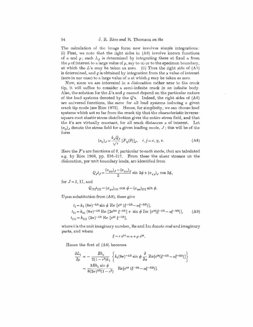
'l'he cnlculation of the irmtge force now involves simple integrations: (i) First, we note thttt the l'ight sides in (AO) involve !mown functions of IX and p ; each LJ is determined by integrating these at fixed IX from the p of interest to a large value of p, say to co or to the specimen boundary, n.t which the L's may be tal(en as zero. (ii) Thus the right side of (A 7) is determined, and g is obtained by integration from the a value of interest (zero in our cnse) to a la.r·ge value of a n.t which g may be taken as zero.
Now, since we are interested in n. dislocation rather neo.r to the crack tip, it will liuffice to consider a semi-infinite crack in an infinite body. Also, the solution for the L'a and y cannot depend on the particular nature of the load systems denoted by the Q's. Indeed, the rigllt sides of (A6) are universal functions, the same for all load systems inducing a given crack tip mode (see Rice 1972). Hence, for simplicity, we can choose load systems which act so far from the crack tip that the characteristic inversesquare-root elastic stress distribution gives the entire stress field, and that the k's are virtually constant, for all cra.clt distances a of interest. Let (a11)J denote the stress field for a given loading mode, J; this will be of the form
(a11)J= kJ!QJ [F11(0)1J, i,j=x, y, z. '\ 1'
(A8)
Here the F's are functions of 8, particular to each mode, that are tabulated e.g. by Rice 1968, pp. 216-217. From these the shear stresses on the dislocation, per unit boundary loads, are identified from
Q t = (am,lJ-(axxlJ sin 2.J.+( ) cos QJ. J J 2 "t' (]XII J "'#">
for J =I, II, and
Qmtm = (a11.chn cos 4>- (a :c.hn sin rp.
Upon substitution from (AS), these give
t1=k1 (87T)-112sin rp Re [el'~~ (f-11~-af-312)],
tu"" k11 (811)-1/2 Re [2e2 •'~~ e-112] + sin rp Im [el"'(t-112- cxe-312)], (A9)
tm = km (271)-I/2 Re [el<~> e-lla],
where i is the unit imaginai·y number, Re and Im denote reu.l and imaginary parts, and where
e = 1' eto = (X+ p el4>.
Hence the first of {A6} becomes
..

Dw;tile Ve1'8'U8 b1·ittle behaviou1· of crystals 95
Multiplying by dp a.ncl recognizing that c1'~'clp=~. so tho.t integration on p becomes integration on ~ inside the bmckets, we have
L = 3Ebc sin if> Re[- 2i:-l/2 2 cxl:-3/2] I 8(21T)ll2(1-v2) S +!!" s
- Ebe [ . -~., B . -~., 8) 30] = 4( l _ 112) ( 21T,·)l/2 3 Sill 'I' COS 2 - Sill ('I'- COS 2 , (AIO)
where the constant of integration is chosen so that L 1 vanishes at p = oo. In a similar way we find
L - Ebc [ -~., B . -~., . 8 . (-1.. 8 . 38] 11 = 4(1 _ 112)( 2m·)ll2 2 cos 'I' cos 2 - am 'I' sm 2 + sm "'- ) am 2
-Eb 8 Lm = 2{ I + v) (2~,.)at2 cos 2 . (All}
Now that the L's are lmown, we have determined the effect of the dislocation on the stress intensity factors J(J (A4) and, further, we can substitute into (A 7) to determine the image force. Since each of the L's is proportional to ?·-112 , (A 7) is of the form
(}g = - ~ [Q(8, rp)J Ocx dp t' '
where
But by using the relations
!_ =cos(}!_ _ sin 8 !_ !_ = cos (if>_ 8) !_ _ sin (t/>- 8) !_ &ex &t· 1· ao ' op o1· 1· ao
between partial derivatives, one may readily derive the identify
_ !_ [Q(8, if>~]=!_ [sin .(r/>-0) Q(8, cp)J· op 1' 001. am (} 1'
(Al2)
This lets us integrate (Al2) immediately. We must, however, append a 'constant' of integration, which may depend on p ( =1· sin 9fsin rp), and which assures tho.t g--+0 as tX--+00. This means that g--+0 as ?'--+<X>, 0--+0 in snch a way that ,. sin (J remains finite. Integration of (A 12) subject to this condition gives the imo.ge force
sin (if>- 8) Q(O, cp} - sin tf>Q(O, cp) g= . () '
?'Sin (Al3}
where Q is defined from (A l 0, 11) via (A l2).

06 J. R. Itice and R. 'l'homson on the
In the text of the paper we were concerned with the cnse {)( = 0, so that 8 = rp and 1' = p. In that case
Q(O, rp) Eb0
2 Eb112
y= --p-=- 81r(l-v2)p- 81r(l+v)p' (A14)
whet·e the lattet· form comes from identifying Q(O, rp), which is found to be independent of rp. Remarkably, this is the same imo.ge force as for a dislocation line at distance p along its slip plane from the boundary of a half-space. In fact, the result for this latter case is also obtainable from (A 13) by letting the c1·ack tip pass far beyond the site of the dislocation, et--~- oo. This means that we let e~. r--Ht) while keeping r sin 9 finite (iL equals p sin ,P). By direct evaluation one finds that Q(1r, cp) = 0, so thE~t lihe image force from the half-space boundary is also given by (Al4).
REFERENCES
ARMSTRONG, R., 1966, Jlt!ater. Sci. Engng, 1, 251. ATKINSON, C., 1966, Int . J. jmctu1·e Jlt!ech., 2, 567. BENSON, G., and BALK, P., 1959, J. phys. Chem., 63, 1009. BENSON, G. C., and BENSON, G. W., 1955, Can. J. Ohem., 33, 232. BENSON, G., SCHREIBER, H., and ZEGOEREN, F. VAN, 1956, Oan. J. Ohem., 34,
1553. Bun.Ns, S., 1970, Acta metall., 18, 969. BuRNS, 8., and WEBB, W., 1970, J. appl. Pkys., 41,2078,2086. CLASS, W., 1964, Ph.D. Thesis, Columbia University. CORDWELL, J., and HULL, D., 1969, Phil. !r[ag., 19, 951. GILMAN, J., 1960, J. appl. Phys., 31, 2208. HIRTH, J., ancl LOTHE, ,J., 1968, Theory of Dislocation8 (New York: McGraw-
Hill). HsEm, C., and THoMSON, R., 1973, J. uppl. Phys., 44, 2051. KELLY, A., 1066, Stt-onu Solids (London: Oxford University Pross). KELLY, A., TYSON, W., and CoTTRELL, A., 1967, Phil. Mag., 15,567. KINGERY, W ., 1954, J. Am. Oeram. Soc., 37, 42. KrrA.7IMA, K., 1966, Proceerlings of the Fit·st lnt~rnalum.al Conference on Ft·ac
ture, Vol. 2 (Send.a.i). MAcMILLAN, N., and KELLY, A., 1972, Proc. R. Soc., 330, 291. MARJ{WORTH, A., KANNINEN, M., and GEHLEN, P., 1973, Proceedings of the
International Oonfe1'ence on Stre$8 Co1·rosion, Or·acking and Hydmgen Embriltlement of Iron Baserl Alloys (Nn.tl. Assn. Corr. Eng., Houston, Texas).
MAITLAND, A., and C:HADWIOR, G., 1969, Phil. Mag., 19, 645. RIOE, J., 1968, Ft·acture, Vol. 2, edited by H. Liebowitz (New York: Academic
Press), p. 191; 1972, Int. J. Solids Struct., 8, 751. TETELMAN, A., and RonERTSON, W. , 1063, Acta metaU., 11, 415. Tos1, M., 1964, SoU.<l State Physic$, Vol. 16, edited by 1~. Seitz and D. Turnbull
(New York: Academic Press). WIEDERHORN, S., 1969, J. Am. Cem1n. 8oc., 52, 485. WIEDERHORN, S., VosEs, R., and BEAN, B., 1970, J. A1n. Octmn. Sao., 58, 18.
SURFACE ENERGY REFERENCES
(1) TAYLOR, J. W., 1954, Jl'Jetallu,·gia, 50, 161. (2} Structure and p,·operties of Solid Surfaces, Hl52, edited by R. Gomer o.nd
C. Smith (Chicago: University of Chicago Pt•ess); Gt'ain Bounda1·ies i1~ .1l1etals, 1957, by D. McLean (LOJldon: Oxforcl University Press), p. 76.

•
Ductile versus brittle behaviotf-1' of crystals 97
(3) INMAN, M., and TIPLER, H., 1063, Metall. Rev., 8, 105. (4) PmoE, A., HALL, M., a.nd GREENOUGH, A., 1964, Acta metull., 12, 49;
INMAN, M., and Tll'LER, H., 1963, Metall. Rev., 8, 105. (6) CoRDWELL, J., and HULL, D., 1969, Phil. Mag., 19,951. (6) BURNS, S., and WEBB, W., 1970, J. appl. Phys., 41, 2078, 2086. {7) Tosr, M., 1964, Sotid State PhysiC8, Vol. 16, edited by F. Seitz and D.
Turnbull (New York: Academic Press}; see also MAOMILLIAN , N ., a.nd KELLY, A., 1972, Proc. R. Soc., 380, 291.
(8) CLASS, W., 1964, Ph.D. thesis, Columbia University. (0) MAITLAND, A., a.nd CKADWICK, G., 1969, Phil. Mag., 19, 645.
(10) WIEDERHORN, S., 1969, J. Am. Oeram. Soc., 52, 485. (ll) KINGERY, W., 1954, J. Am. Oeram. Soc., 87, 42. (12) HAWKINS, W., 1941, J. chem. Phy8., 10,269.