A micromechanical fracture model for ductile-brittle ...
77
Purdue University Purdue e-Pubs Open Access eses eses and Dissertations January 2016 A micromechanical fracture model for ductile- brile interfaces Dhrubajyoti Daa Purdue University Follow this and additional works at: hps://docs.lib.purdue.edu/open_access_theses is document has been made available through Purdue e-Pubs, a service of the Purdue University Libraries. Please contact [email protected] for additional information. Recommended Citation Daa, Dhrubajyoti, "A micromechanical fracture model for ductile-brile interfaces" (2016). Open Access eses. 1237. hps://docs.lib.purdue.edu/open_access_theses/1237
Transcript of A micromechanical fracture model for ductile-brittle ...
Purdue UniversityPurdue e-Pubs
Open Access Theses Theses and Dissertations
January 2016
A micromechanical fracture model for ductile-brittle interfacesDhrubajyoti DattaPurdue University
Follow this and additional works at: https://docs.lib.purdue.edu/open_access_theses
This document has been made available through Purdue e-Pubs, a service of the Purdue University Libraries. Please contact [email protected] foradditional information.
Recommended CitationDatta, Dhrubajyoti, "A micromechanical fracture model for ductile-brittle interfaces" (2016). Open Access Theses. 1237.https://docs.lib.purdue.edu/open_access_theses/1237

Graduate School Form 30 Updated 12/26/2015
PURDUE UNIVERSITY GRADUATE SCHOOL
Thesis/Dissertation Acceptance
This is to certify that the thesis/dissertation prepared
By
Entitled
For the degree of
Is approved by the final examining committee:
To the best of my knowledge and as understood by the student in the Thesis/Dissertation Agreement, Publication Delay, and Certification Disclaimer (Graduate School Form 32), this thesis/dissertation adheres to the provisions of Purdue University’s “Policy of Integrity in Research” and the use of copyright material.
Approved by Major Professor(s):
Approved by: Head of the Departmental Graduate Program Date
DHRUBAJYOTI DATTA
A MICROMECHANICAL FRACTURE MODEL FOR DUCTILE-BRITTLE INTERFACES
Master of Science in Civil Engineering
AMIT VARMACo-chair
VIKAS TOMAR Co-chair
AYHAN IRFANOGLU
AMIT VARMA, VIKAS TOMAR
DULCY ABRAHAM 04/14/2016
i
i
A MICROMECHANICAL FRACTURE MODEL FOR DUCTILE-BRITTLE
INTERFACES
A Thesis
Submitted to the Faculty
of
Purdue University
by
Dhrubajyoti Datta
In Partial Fulfillment of the
Requirements for the Degree
of
Master of Science in Civil Engineering
May 2016
Purdue University
West Lafayette, Indiana

ii
ii
For Ma and Baba

iii
iii
ACKNOWLEDGEMENTS
I am highly grateful and indebted to my advisors, Dr. Amit Varma and Dr. Vikas Tomar,
whose understanding, expertise and generous guidance made it possible for me to pursue
this interdisciplinary topic which was of great interest to me.
I would also like to thank Dr. Ayhan Irfanoglu for serving on the examining committee
and providing constructive critiquing, comments and suggestions.
I express my deepest gratitude to all my professors, whose inputs have allowed me to
develop the fundamental concepts which were quintessential to refine my research.
I would like to thank the administrative staff at Structures area of Lyles School of Civil
Engineering department for helping with the formatting requirements and other
formalities.
Lastly, I would express my sincere gratitude to my colleagues at Bowen Laboratory and
Interfacial Multiphysics Laboratory for providing useful inputs.
iv
iv
TABLE OF CONTENTS
Page
LIST OF TABLES ............................................................................................................. vi
LIST OF FIGURES .......................................................................................................... vii
LIST OF ABBREVIATIONS ............................................................................................ ix
ABSTRACT ........................................................................................................................ x
CHAPTER 1.INTRODUCTION AND BACKGROUND ................................................. 1
CHAPTER 2.ANALYTICAL METHODOLOGY ............................................................ 6
2.1. Controlled volume fracture model of the steel-concrete interface ................ 8
2.2. Application of J-Integral to interface crack propagation ............................ 12
2.3. Modified fracture model to consider plasticity effects at interface
crack tip and impinging effect .................................................................... 17
2.4. Empirical evaluation of fracture toughness parameters and stress
intensity factors ........................................................................................... 20
CHAPTER 3.ILLUSTRATIVE APPLICATIONS .......................................................... 22
3.1. Fracture of the shear connector-microstructure-steel plate interface .......... 22
3.1.1. Modified J-Integral model to compensate for tension softening and
singularity at crack tip ................................................................................ 22
3.1.2. Application of J-Integral for crack path propagation due to slip
of steel plate ................................................................................................ 25
3.2. Application of J-Integral for stud-microstructure interface due to
pullout ......................................................................................................... 27
3.3. Size effect on fracture energy release into process zone ............................ 29
3.4. Microstructural damage of the reinforcement-concrete interface
when subjected to pullout forces ................................................................. 31
v
v
Page
3.4.1.Elasto-plastic fracture model for rebar specimen embedded in
concrete ...................................................................................................... 32
3.5. Constitutive elasto-plastic modelling for pseudo-static SSI ...................... 36
CHAPTER 4.COMPUTATIONAL IMPLEMENTATION .................................. .......... 40
4.1. ABAQUS implementation ......................................................................... 42
4.2. Results and discussions .............................................................................. 44
4.2.1. Analysis of stress/displacement fields and computation of SIF ................ 45
4.2.2. Crack growth characteristics and computation of Strain Energy
Release Rate .............................................................................................. 51
CHAPTER 5.CONCLUSIONS ........................................................................................ 54
BIBLIOGRAPHY .............................................................................................................58

vi
vi
LIST OF TABLES
Table .............................................................................................................................. Page
1. Stress Intensity (K) Factor estimates of contour integrals (n=3) for concrete-concrete
interfacial crack .............................................................................................................. 48
2. Stress Intensity (K) Factor estimates of contour integrals (n=3) for steel-concrete
interfacial crack .............................................................................................................. 49
3. Comparison of computed fracture energy with existing model for concrete ................ 50
vii
vii
LIST OF FIGURES
Figure ............................................................................................................................ Page
1. Controlled volume with area A and surface boundary S with rough interface ............... 9
2. Correlation between displacement of controlled volume and crack tip propagation .... 10
3. Stress-strain relation assumed at interface to obtain strain energy ............................... 12
4. Remote integral path for obtaining J-Integral at the steel-concrete interface ............... 13
5. Elemental area enclosed by boundaries S1 and S
2 separated by a .............................. 15
6. (a)Contour surrounding the plastic zone: Dugdale model (b)Stresses and traction fields
surrounding plastic zone ............................................................................................... 18
7. Impinging of cracks near the interface .......................................................................... 20
8. Failure modes for the stud-concrete-steel plate interface ............................................. 23
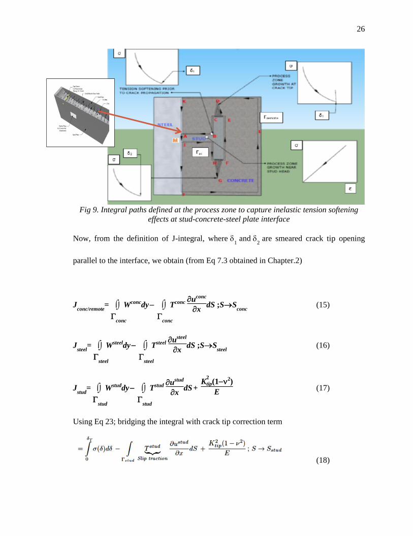
9. Integral paths defined at the process zone to capture inelastic tension softening
effects at stud-concrete-steel plate interface ..................................................................... 26
10. Integral path for the stud-concrete-steel plate interface when subjected to pullout
forces ............................................................................................................................ 28
11. a)Idealised shear force-slip diagram for deformable connectors (Bazant et
al.1999[18])(b)Idealised plastic zone formation and post peak tension softening ....... 30
12. EPFM model of rebar specimen subjected to pullout forces subdivided into failure
zones ............................................................................................................................. 34
13. Magnified image of contour surrounding tension softening zone around crack
originating from shear lug ............................................................................................ 35
14. Modified direct shear tests with interface parameters and strain hardening/softening
effects during critical phase ......................................................................................... 38
15. Crack front propagation using enriched Heaviside function in XFEM ...................... 40
viii
viii
Figure Page
16. Undeformed FE model for the steel-concrete interface .............................................. 44
17. Stress field contour S11 and S22 for static crack across concrete-concrete interface ... 45
18. Stress field contours, S11 and S22 for static crack across steel-concrete interface ....... 46
19. Displacement field contours, U2 for (a) concrete-concrete interface and (b) steel
concrete interface................................................................................ ...................... 46
20. (a) S11 (b) S22 (c) U2 (d) PHILSM for crack propagating along concrete-concrete
interface......................................................................................................... ............ 51
21. (a)S11(b)S22 (c)U2 (d)PHILSM for crack propagating along steel-concrete interface 52
22. SERR for uni-material interface crack under opening mode loading ........................ 52
23. SERR for bi-material interface crack under opening mode loading.... ....................... 53
24. F vs CTOD for bimaterial interface crack under opening mode loading ................... 53

ix
ix
LIST OF ABBREVIATIONS
SC: Steel Concrete
CTOD: Crack Tip Opening Displacement
SERR: Strain Energy Release Rate
SIF: Stress Intensity Factor
VCCT: Variable Crack Closure Technique
pz: process zone
XFEM: eXtended Finite Element Method
MAXPS: Maximum Principal Stress
SSI: Soil Structure Interaction
x
x
ABSTRACT
Datta, Dhrubajyoti. M.S.C.E., Purdue University, May 2016. Micromechanical fracture
model of ductile-brittle bimaterial interface. Major Professors: Dr. Amit H. Varma and
Dr. Vikas Tomar.
The micromechanical properties of a bimaterial interface depend on the (i) bonded slip
and friction parameters (ii) release of fracture energy during crack growth and (iii)
propagation, residual energy and shape formulations defining the failure envelope. A
non-empirical fracture model is proposed for a ductile-brittle bimaterial interface. Such
interfaces occur in Steel-Concrete (SC) composite wall modules, which are building
blocks of nuclear and containment facilities. Similar bimaterial interfaces can occur in
geotechnical structures, aerospace, ceramics and other composite applications. The thesis
identifies the primary microstructural failure modes associated with such interfaces. A
controlled volume fracture model for adhesively bonded interfaces is used in conjunction
with Rice’s [1] path independent J-Integral to correlate the strain energy release
rate(SERR) to traction slip parameters. The linear elastic fracture model is modified to
account for plasticity effects in the process zone and derive the crack tip opening
displacement (CTOD). Numerical evaluation of fracture toughness parameters is
performed to study impinging effects and determination of stress intensity factors.
Depending on the nature of interface under consideration; appropriate tension

xi
xi
softening/hardening laws are incorporated to capture the phase transformation of crack
propagation in the expression of J for remote integral paths,.
1
1
CHAPTER 1. INTRODUCTION AND BACKGROUND
Interfaces have always played a crucial role in material design, structural behavior, and
biological transport phenomenon. The junction between two surfaces is not just an
assumptive parameter but exhibits properties characteristic to both materials, and helps in
facilitating transfer of stresses or tractions.
Ductile-brittle interfaces are an intrinsic part of aviation composite laminates,
structural steel-concrete composites, ceramics, retrofits, and soil-structure interaction
problems. In the field of composites, delamination is possibly the most critically studied
failure mode, generally presumed to occur at the interface between adjoining plies and
regarded as a fracture phenomenon between anisotropic layers. The Virtual Crack
Closure Technique [2] was established on Irwin’s argument that if a crack undergoes
extension, the energy absorbed during the process is equivalent to the work done to close
the crack to its initial configuration. It was developed to understand the strain energy
release rate, interlaminar tension and scissoring shear stresses at discontinuities that result
in mixed-mode delamination. As far as non-linearity and directionality is concerned;
VCCT’s application is limited to thin layered plane stress problems, since only cracks
with single tip openings can be propagated. Presence of oscillating singularities at crack
2
2
tip makes it difficult to assess the energy release into the process zone. The tensile
fracture behavior of mechanically nanostructured unreinforced alloys (Al-Al2O
3 being the
most popular) and fuselage-stringer welds are of prime importance to the aerospace
industry. Insufficient bonding conditions pertaining to time, temperature and pressure
lead to void formation, precipitation of undesired phases or undesired growth of fused
grains resulting in interfacial cracks [3]. Experimental investigation suggests failure of
Al2O
3-metal interface occurs due to plastic deformation of metal matrix and elastic
separation of alumina particulates with degradation of tensile ductility suggesting strain
softening. Separation occurs at matrix process zone rather than reinforcing alumina. Most
bimaterial energy-based fracture models fall short of defining the crack initiation
criterion and accounting for plasticity effects of such interfaces. Recent studies indicate
that interfaces play a key role in addressing durability requirements for ceramics and bi-
layered structural materials subjected to progressive corrosion and moisture effects.
Humid environment can have detrimental effects on reinforced concrete elements
wrapped with FRP sheets after prolonged exposure. Cracks can either propagate in bulk
media (material decohesion) or along the interface (material separation)[4]. In coastal
areas corrosion of concrete due to chloride ingress or sulfate attack is a common thermo-
chemical phenomenon; which can be explained as a pseudo-static process allowing crack
fronts to initiate through internal microscopic volume expansion.
The fundamental marker for interfacial fracture of bimaterials is the fracture
energy associated with it; and is responsible for influencing micromechanical properties
(stress intensity factors and fracture toughness parameters) of composites, the damage of
3
3
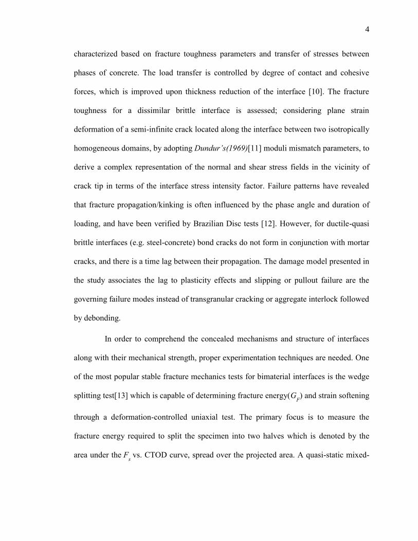
bonds and delamination of thin films. The strain energy usually exceeds the
thermodynamic work of adhesion due to mode mixity (shearing and opening) and
presence of segregants at the interface; shielding caused by roughness and plasticity at
crack tip [5]. The primary aim of interfacial fracture mechanics is to define the toughness
parameter which characterizes fracture resistance. Solutions to such plane problems of
interfacial cracks in heterogeneous media were presented half a century ago. On
considering dissimilar materials with semi-infinite cracks, it was observed that stresses
possess an oscillating singularity at crack tip [6], and this was further expanded to the
case of flexural loading [7]. The eigen-function expansion approach adopted failed to
quantitatively characterize stresses in the immediate vicinity of the crack tip [6], and was
later integrated with complex potential functions to provide satisfactory evaluation of
stress intensity factors [8]. The complex stress intensity factor ignored contact and was
valid only for small scale non-linear behavior or negligible contact zone at the crack tip,
which requires alteration of magnitude and phase angle of combined shear or tensile
loading [9].
The present work focuses on developing models that can surpass difficulties [6, 7,
15, 19] associated with singularities at crack tip using fundamental energy conservation
principles without delving into complex mathematical formulations. The model presented
treats the interface crack as a boundary value problem; and is capable of computing strain
energy release rates and crack tip opening displacements from specified far field stresses
and tractions using path independent contour integrals.
In view of efforts to develop high performance concrete (a brittle bimaterial
composed of mortar and matrix), deformations of mortar-matrix interface are
4
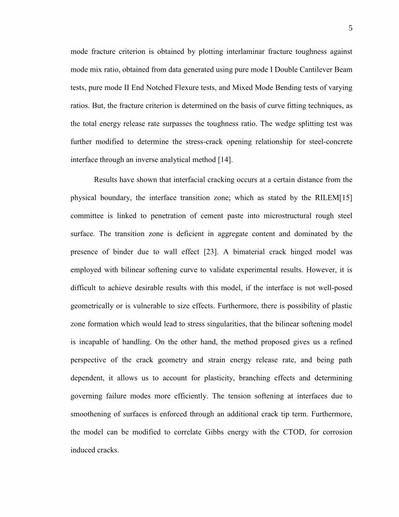
4
characterized based on fracture toughness parameters and transfer of stresses between
phases of concrete. The load transfer is controlled by degree of contact and cohesive
forces, which is improved upon thickness reduction of the interface [10]. The fracture
toughness for a dissimilar brittle interface is assessed; considering plane strain
deformation of a semi-infinite crack located along the interface between two isotropically
homogeneous domains, by adopting Dundur’s(1969)[11] moduli mismatch parameters, to
derive a complex representation of the normal and shear stress fields in the vicinity of
crack tip in terms of the interface stress intensity factor. Failure patterns have revealed
that fracture propagation/kinking is often influenced by the phase angle and duration of
loading, and have been verified by Brazilian Disc tests [12]. However, for ductile-quasi
brittle interfaces (e.g. steel-concrete) bond cracks do not form in conjunction with mortar
cracks, and there is a time lag between their propagation. The damage model presented in
the study associates the lag to plasticity effects and slipping or pullout failure are the
governing failure modes instead of transgranular cracking or aggregate interlock followed
by debonding.
In order to comprehend the concealed mechanisms and structure of interfaces
along with their mechanical strength, proper experimentation techniques are needed. One
of the most popular stable fracture mechanics tests for bimaterial interfaces is the wedge
splitting test[13] which is capable of determining fracture energy(GF) and strain softening
through a deformation-controlled uniaxial test. The primary focus is to measure the
fracture energy required to split the specimen into two halves which is denoted by the
area under the Fs vs. CTOD curve, spread over the projected area. A quasi-static mixed-
5
5
mode fracture criterion is obtained by plotting interlaminar fracture toughness against
mode mix ratio, obtained from data generated using pure mode I Double Cantilever Beam
tests, pure mode II End Notched Flexure tests, and Mixed Mode Bending tests of varying
ratios. But, the fracture criterion is determined on the basis of curve fitting techniques, as
the total energy release rate surpasses the toughness ratio. The wedge splitting test was
further modified to determine the stress-crack opening relationship for steel-concrete
interface through an inverse analytical method [14].
Results have shown that interfacial cracking occurs at a certain distance from the
physical boundary, the interface transition zone; which as stated by the RILEM[15]
committee is linked to penetration of cement paste into microstructural rough steel
surface. The transition zone is deficient in aggregate content and dominated by the
presence of binder due to wall effect [23]. A bimaterial crack hinged model was
employed with bilinear softening curve to validate experimental results. However, it is
difficult to achieve desirable results with this model, if the interface is not well-posed
geometrically or is vulnerable to size effects. Furthermore, there is possibility of plastic
zone formation which would lead to stress singularities, that the bilinear softening model
is incapable of handling. On the other hand, the method proposed gives us a refined
perspective of the crack geometry and strain energy release rate, and being path
dependent, it allows us to account for plasticity, branching effects and determining
governing failure modes more efficiently. The tension softening at interfaces due to
smoothening of surfaces is enforced through an additional crack tip term. Furthermore,
the model can be modified to correlate Gibbs energy with the CTOD, for corrosion
induced cracks.
6
6
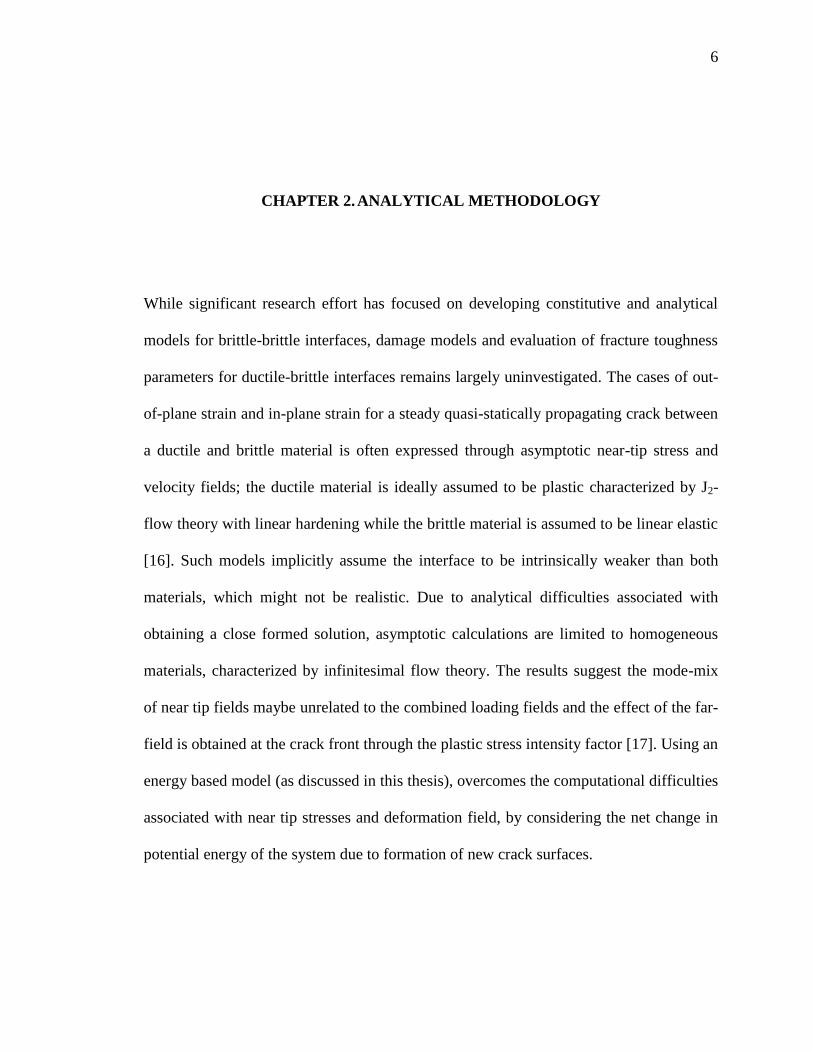
CHAPTER 2. ANALYTICAL METHODOLOGY
While significant research effort has focused on developing constitutive and analytical
models for brittle-brittle interfaces, damage models and evaluation of fracture toughness
parameters for ductile-brittle interfaces remains largely uninvestigated. The cases of out-
of-plane strain and in-plane strain for a steady quasi-statically propagating crack between
a ductile and brittle material is often expressed through asymptotic near-tip stress and
velocity fields; the ductile material is ideally assumed to be plastic characterized by J2-
flow theory with linear hardening while the brittle material is assumed to be linear elastic
[16]. Such models implicitly assume the interface to be intrinsically weaker than both
materials, which might not be realistic. Due to analytical difficulties associated with
obtaining a close formed solution, asymptotic calculations are limited to homogeneous
materials, characterized by infinitesimal flow theory. The results suggest the mode-mix
of near tip fields maybe unrelated to the combined loading fields and the effect of the far-
field is obtained at the crack front through the plastic stress intensity factor [17]. Using an
energy based model (as discussed in this thesis), overcomes the computational difficulties
associated with near tip stresses and deformation field, by considering the net change in
potential energy of the system due to formation of new crack surfaces.
7
7
Mathematical representation of interface failure interactions have been primarily
described through the lumped and distributed model. In the lumped model, the damage
and nonlinearities are confined to an interface of zero thickness; while for the latter,
cumulative effects are smeared over a layer of finite thickness. While the actual interface
is rough or ribbed due to damaged asperities, the lumped model idealizes it to be smooth.
The traction-displacement relationships are expressed through normal and tangential
stiffness factors in conjunction with a damage multiplier to generate a non-linear
evolution equation defining failure energy for slip to occur by overcoming adhesion [18].
Such cohesive models with linear traction-separation laws are modelled on basis of
experimental data and are limited in application. Most practical interfaces present higher
resistance than adhesive or friction effects and develop post peak softening or hardening.
Within such limitations, the present work offers an insight towards developing a
comprehensive model for ductile-brittle interfaces that is independent of shape effects or
geometric asperities at crack tip. Its functionality can be modified to include tension
softening/hardening effects for irreversible equivalent strains and size effects. Depending
on independently chosen contour paths, computation of the J-Integral would decide the
governing failure mode.
The thesis primarily focuses on steel-concrete interface configurations of practical
importance subjected to varied loading and failure criterion to depict the versatility of the
analytical model.
8
8
2.1. Controlled volume fracture model of the steel concrete interface
Path-independent integrals derived from energy conservation laws, are used for
determining the intensity of singularity in a field when the exact shape or configuration of
the field in the vicinity of crack tip is unknown. They are formulated using a continuously
differentiable field whose properties are well-defined in its domain. The benefit of the
formulation lies in the fact that if a point singularity exists, the integral can be applied to
the domain excluding the singularity making it ideal for computing fracture parameters in
spite of dislocation or inclusion defects. The J-Integral is identical to energy release rate
for a plane crack extension [1] and it plays the role of an intensity factor for singular
stress and strain fields at the crack tip of a power law hardening material [19]. For the
model proposed, the quasi static crack propagation is assumed to be time independent and
is limited to hyper-elastic materials with stress-free crack borders. Furthermore, the
contour integral is incapable of handling bimaterial interfaces especially if it consists of
brittle material (concrete) on one side and a ductile surface (steel) on the other. Hence, it
is modified to incorporate the strain-hardening post peak plastic response of the steel
interface using Dugdale’s (1960) [20] elasto-plastic fracture model. Although it is well
known that steel does not exhibit a complete elasto-plastic behavior, in the proximity of
micro cracks the geometric non-linearities can be ignored.
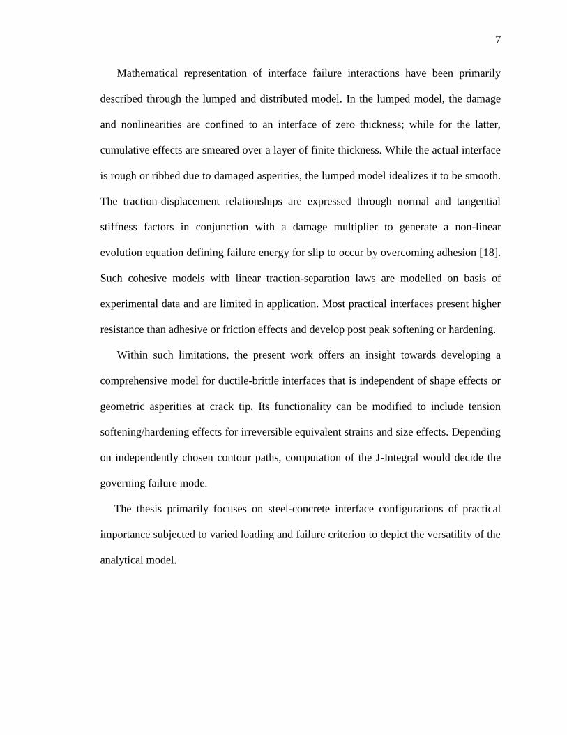
The steel-concrete interface is modelled assuming a negligible interface thickness
between them such that fracture energy released in the fracture process zone (FPZ) is a
result of overcoming the adhesive forces. Consider an interfacially cracked steel-concrete
composite section with thickness t, area A and boundary S, for which the entire volume is
controlled.
9
9
Fig 1. Controlled volume with area A and surface boundary S with rough interface
When this section experiences surface traction T along the boundary
S(experimentally simulated by step loading), the potential energy in the controlled
volume is given by
=
A
U dA
S
T.u dS t=
A
U dA
S
Ti.u
i dS t (1)
where, U:Strain energy density; u:displacement vector.
If the crack is extended by a, potential energy of the control volume should also change
Let, PE of the control volume before crack extension: 1 and the PE of the control
volume after crack extension: 2.
The potential energy release rate is then given by
A=lim
a0
2
1
t.a (2)
LARGE DOMAIN
10
10
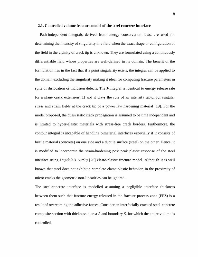
Assuming the module to be part of an infinitely large structure, the potential energies 1
and 2 can be computed by keeping the crack length fixed and moving the controlled
model by the same amount towards the left as the crack propagates towards the right i.e.
Δa.
Fig 2. Correlation between displacement of controlled volume and crack tip propagation
(as crack propagates towards right the control volume moves towards left)
Before we derive the potential energy release due to crack propagation it is essential to
define the nature of the strain energy to be considered for this model. Concrete is a
bimaterial, brittle in nature and exhibits catastrophic failure characteristics. The variation
of internal energy (δE) stored in a body can be expressed in terms of the variation of
strain energy density (δU).
(2.1)
If variation of external work is denoted by W, it can be related to applied body force ( fi),
surface traction (Ti) and variation in displacement as
SECTION HIGHLIGHTED IN BLACK OUTLINE REPRESENTS PROPAGATION OF
CONTROLLED VOLUME TOWARDS LEFT DUE TO CRACK EXTENSION, WHILE
RED OUTLINE REPRESENTS INITIAL POSITION
Δ Δ
11
11
(2.2)
Hence we can assert that the external work done must be equivalent to the total increment
in strain energy of the material.
δE = δW (2.3)
(2.4)
After performing necessary substitutions and applying Gauss divergence theorem;
(2.5)
Since, σij, j+ fi = 0, the preceding equation can be simplified as
(2.6)
Hence, δU = σij δεij (3)
From Eq(3), the stress strain relation can be obtained by assuming relevant expression of
U0 in terms of strain components applying Green’s approach (say, if we assume the strain
energy density to be a quadratic function, then U=D0 + Dkl εkl + Dklmn εkl εmn). But for our
model we prefer to stay in the linear elastic fracture mechanics domain, for which we
assume a linear strain energy density which gives a linear stress-strain relation σij = Dijkl
εkl. From the above expression it is clear that we can express U as area under the linear
curve, which may be obtained from experimental data.
12
12
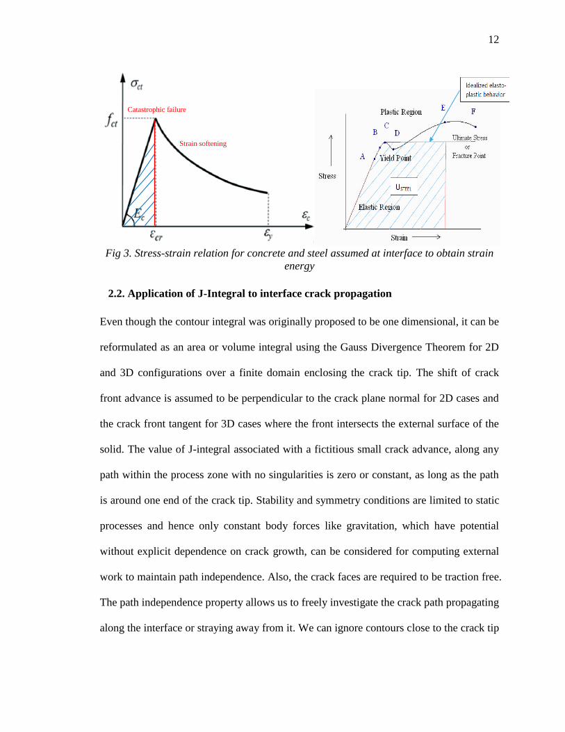
Fig 3. Stress-strain relation for concrete and steel assumed at interface to obtain strain
energy
2.2. Application of J-Integral to interface crack propagation
Even though the contour integral was originally proposed to be one dimensional, it can be
reformulated as an area or volume integral using the Gauss Divergence Theorem for 2D
and 3D configurations over a finite domain enclosing the crack tip. The shift of crack
front advance is assumed to be perpendicular to the crack plane normal for 2D cases and
the crack front tangent for 3D cases where the front intersects the external surface of the
solid. The value of J-integral associated with a fictitious small crack advance, along any
path within the process zone with no singularities is zero or constant, as long as the path
is around one end of the crack tip. Stability and symmetry conditions are limited to static
processes and hence only constant body forces like gravitation, which have potential
without explicit dependence on crack growth, can be considered for computing external
work to maintain path independence. Also, the crack faces are required to be traction free.
The path independence property allows us to freely investigate the crack path propagating
along the interface or straying away from it. We can ignore contours close to the crack tip
Strain softening
Catastrophic failure
13
13
where the displacement and stress fields are difficult to compute accurately owing to
stress singularities or presence of a plastic zone, and choose a remote path along the
boundaries or symmetry points of the domain on which the tractions and strain energies
can be deciphered with relative simplicity.
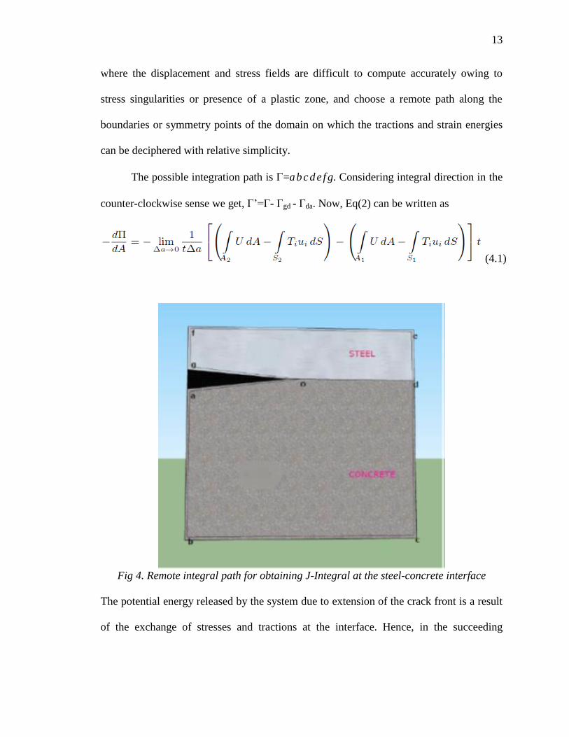
The possible integration path is =a b c d e f g. Considering integral direction in the
counter-clockwise sense we get, Г’=Г- Гgd - Гda. Now, Eq(2) can be written as
(4.1)
Fig 4. Remote integral path for obtaining J-Integral at the steel-concrete interface
The potential energy released by the system due to extension of the crack front is a result
of the exchange of stresses and tractions at the interface. Hence, in the succeeding
14
14
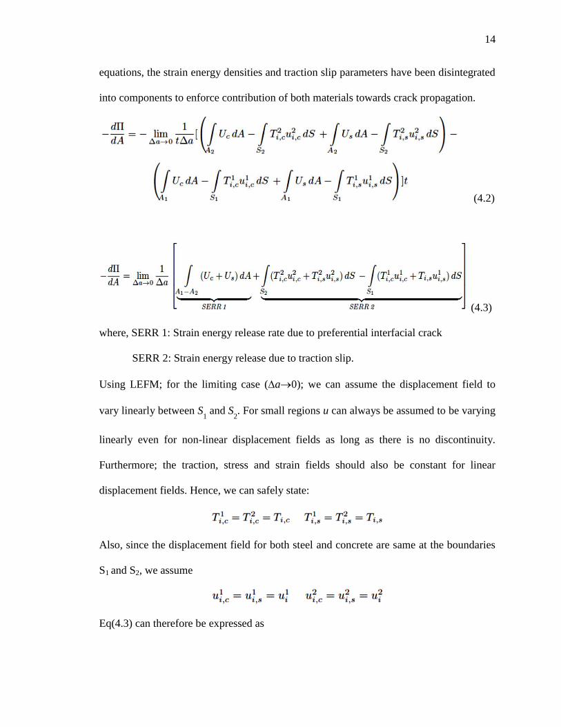
equations, the strain energy densities and traction slip parameters have been disintegrated
into components to enforce contribution of both materials towards crack propagation.
(4.2)
(4.3)
where, SERR 1: Strain energy release rate due to preferential interfacial crack
SERR 2: Strain energy release due to traction slip.
Using LEFM; for the limiting case (a0); we can assume the displacement field to
vary linearly between S1 and S
2. For small regions u can always be assumed to be varying
linearly even for non-linear displacement fields as long as there is no discontinuity.
Furthermore; the traction, stress and strain fields should also be constant for linear
displacement fields. Hence, we can safely state:
Also, since the displacement field for both steel and concrete are same at the boundaries
S1 and S2, we assume
Eq(4.3) can therefore be expressed as
15
15
(5)
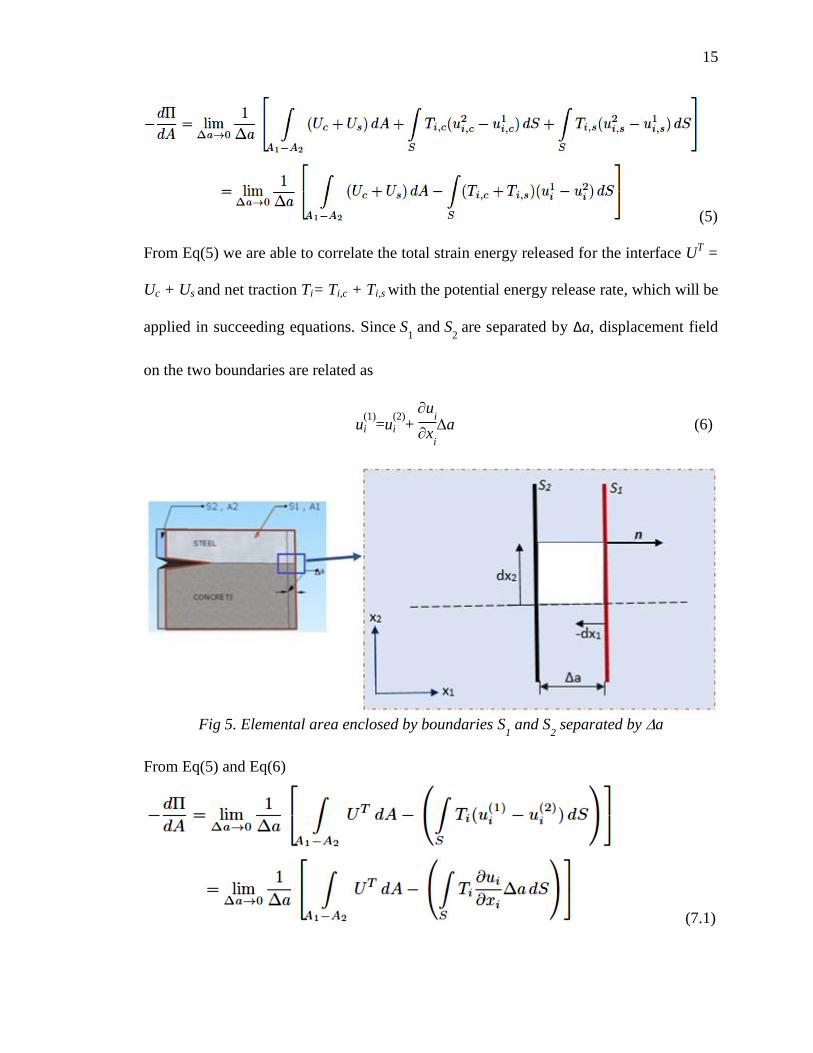
From Eq(5) we are able to correlate the total strain energy released for the interface UT =
Uc + Us and net traction Ti= Ti,c + Ti,s with the potential energy release rate, which will be
applied in succeeding equations. Since S1 and S
2 are separated by Δa, displacement field
on the two boundaries are related as
u(1)
i =u(2)
i + u
i
xi
a (6)
Fig 5. Elemental area enclosed by boundaries S
1 and S
2 separated by a
From Eq(5) and Eq(6)
(7.1)
16
16
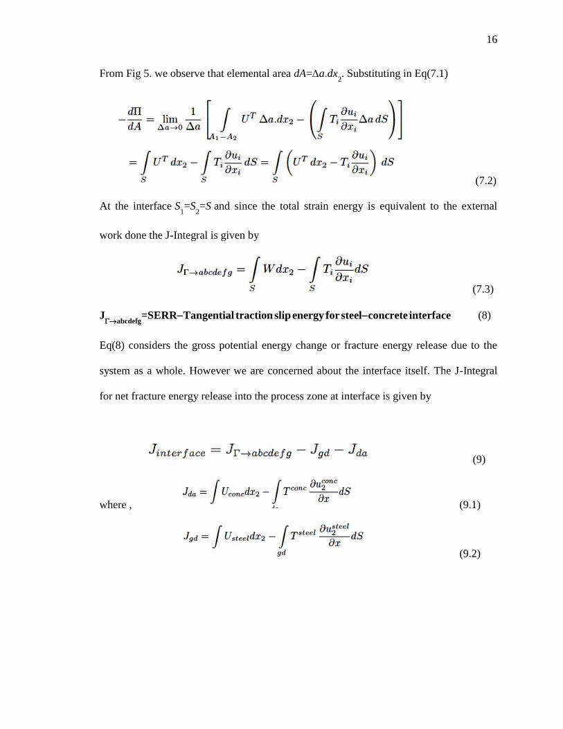
From Fig 5. we observe that elemental area dA=a.dx2. Substituting in Eq(7.1)
(7.2)
At the interface S1=S
2=S and since the total strain energy is equivalent to the external
work done the J-Integral is given by
(7.3)
Jabcdefg
=SERRTangential traction slip energy for steelconcrete interface (8)
Eq(8) considers the gross potential energy change or fracture energy release due to the
system as a whole. However we are concerned about the interface itself. The J-Integral
for net fracture energy release into the process zone at interface is given by
(9)
where , (9.1)
(9.2)
17
17
2.3. Modified fracture model to consider plasticity effects at the interface crack tip
and impinging effect
When hard brittle and ductile metal surfaces come into contact at asperity tips; the
asperities notch into the metal surface causing it to yield plastically due to local stress
concentrations when coupled with diffusional mass transfer, leading to shrinkage of
interfacial voids, allowing the crack tip to propagate. Severe restrictions for J-results can
be attributed to existence of strain energy density which uniquely defines the potential for
deriving stresses. The irreversible plastic deformations, local unloading processes, and
stress rearrangements are concealed from the results. Moreover, for non-homogeneous
stress fields, if the loading is monotonically increasing instead of being pseudo-static, it
does not sufficiently guarantee radial stress paths making the J-integral path dependent
with the onset of plasticity. The expressions derived above do not account for the plastic
zone due to the ductile stretch of the steel interface at the crack tip. For small scale
yielding, the J-Integral can be computed outside the plastic zone if the domain under
evaluation is large enough to cover the plastic zone and passes through the elastic region.
The problem can be addressed by choosing an integral path about the plastic zone for a
Dugdale type plasticity model.
J-integral is carried out on S=Ssteel
U Sconcrete
. The path independence is valid as
long as the material enclosed between the two boundaries is elastic. Since the interface is
inelastic, the equivalence of the strain energy release rate to the J-Integral is invalid in
such a scenario i.e. (JSERR). But, J can still be calculated for the problem geometry and
equated to the crack tip opening displacement (CTOD). Extending Eq(8) to incorporate
plasticity effects:
18
18
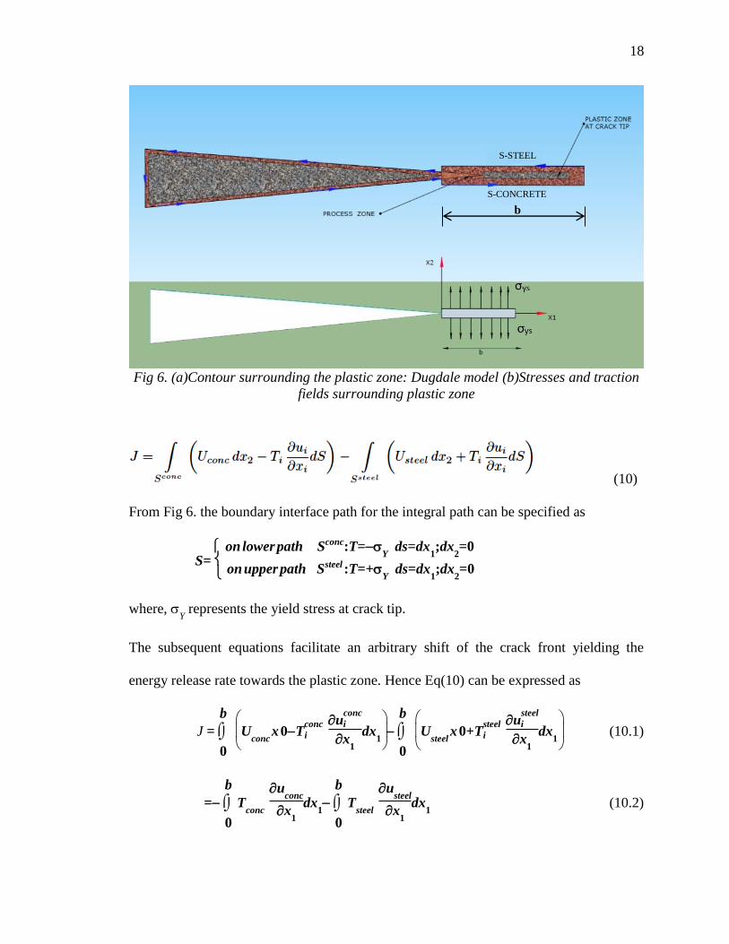
Fig 6. (a)Contour surrounding the plastic zone: Dugdale model (b)Stresses and traction
fields surrounding plastic zone
(10)
From Fig 6. the boundary interface path for the integral path can be specified as
S= on lower path Sconc:T=
Y ds=dx
1;dx
2=0
on upper path Ssteel :T=+Y
ds=dx1;dx
2=0
where, Y represents the yield stress at crack tip.
The subsequent equations facilitate an arbitrary shift of the crack front yielding the
energy release rate towards the plastic zone. Hence Eq(10) can be expressed as
J =
0
b
Uconc
x 0Tconc
i u
conc
i
x1
dx1
0
b
Usteel
x 0+Tsteel
i u
steel
i
x1
dx1
(10.1)
=
0
b
Tconc
u
conc
x1
dx1
0
b
Tsteel
u
steel
x1
dx1 (10.2)
S-STEEL
S-CONCRETE
b
19
19
=Y
0
b
(u
concu
steel)
x1
dx1
(10.3)
=Y [ ]u
concu
steel
b
0 =
Y[CTOD0] (10.4)
Hence, the J-Integral can be related to the elasto-plastic crack tip opening displacement
J = Yield
x CTOD (11)
For large plastic deformations; it should be kept in mind that J being a monotonically
increasing function of the distance from crack tip, crack propagation would lead to
energy production instead of dissipation thereby violating the second law of
thermodynamics. The saturated J value with a incremental domain is always the nearest
to the ‘real’ far field J [21]. The strain energy release ratio for cracks at the interface
depends on the angle at which the crack propagates as well as the material properties.
It is possible, that a given crack might find itself energetically favorable to branch
off the interface and penetrate into either the brittle or ductile media unless the interface
itself is weaker than either phase [16]. The J-integral for cracks emanating at multiple
angles from the crack tip into the material microstructure can provide us with insight
regarding the variation of SERR at the interface and the minimum energy which defines
the failure path. In order to account for impinging effects, the integral path is not allowed
to cross the interface as the fracture parameters would be uni-materialistic for such cases.
Shansuo et al.[22] was able to generate curves for variation of J-Integral with . Using
curve fitting techniques, they were able to arrive at an expression connecting the fracture
energy released by the existing crack to the impinging crack.
20
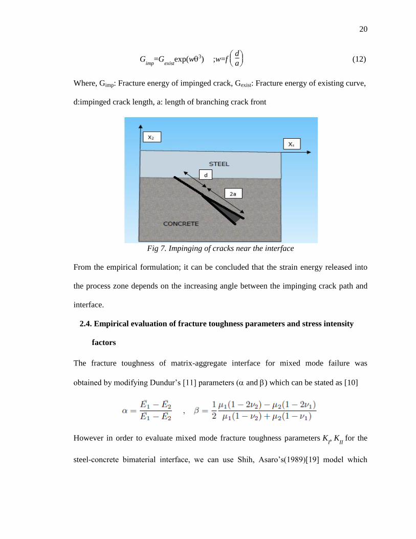
20
Gimp
=Gexist
exp(w3) ;w=f
d
a (12)
Where, Gimp: Fracture energy of impinged crack, Gexist: Fracture energy of existing curve,
d:impinged crack length, a: length of branching crack front
Fig 7. Impinging of cracks near the interface
From the empirical formulation; it can be concluded that the strain energy released into
the process zone depends on the increasing angle between the impinging crack path and
interface.
2.4. Empirical evaluation of fracture toughness parameters and stress intensity
factors
The fracture toughness of matrix-aggregate interface for mixed mode failure was
obtained by modifying Dundur’s [11] parameters ( and ) which can be stated as [10]
However in order to evaluate mixed mode fracture toughness parameters KI, K
II for the
steel-concrete bimaterial interface, we can use Shih, Asaro’s(1989)[19] model which
21
21
considers a periodic array of cracks and prescribes an adhesive relation that governs the
normal and shear displacement response. Assuming to be the loading phase angle
(which is a measure of the shearing displacement or slip to the opening or normal
displacement at the steel concrete interf the coupled SIF’s for mode I and II under far
field tensile stress
22 and shear stress
12, can be stated as
KI+iK
II=(
22+i
12)(1+2i) L
2Li (13)
where,
= 1
2ln
34
c
c
+ 1
s
1
c
+ 34
s
s
The SERR for the plane strain case (Xiong et al.2010[13]) is given as
GI+G
II=
(K2
I+K2
II)
1
c
c
+ 1
s
s
4cosh2()
K2
I+K2
II= 2
n
1n
(Gn
1+Gn
2) ; n=1,2, (14)
In the above expression; L represents the total length of the crack. and represent the
shear modulus and Poisson’s ratio respectively. is constant for the interface and is
predicted to be less than 0.1.

22
22
CHAPTER 3. ILLUSTRATIVE APPLICATIONS
3.1. Fracture of the shear connector-microstructure-steel plate interface
Steel-concrete(SC) composite walls are of great importance to the nuclear energy
industry. It consists of a concrete wall connected to steel plates using shear connectors
and tie rods at well-defined intervals. The steel plate with the connector elements serve as
the formwork for the concrete poured. While a significant amount of research has been
performed on the assessment of local and global failure modes for SC walls, the fracture
origination, propagation and branching at the interface level is yet to be investigated. This
thesis aims at identifying the possible interfaces of the basic SC wall module and
establishes LEFM techniques with inclusion of certain non-linear parameters, to shed
light on certain major fracture parameters that govern the failure of its components.
3.1.1 Modified J-Integral model to compensate for tension softening and
singularity at crack tip
The previous sections dealt with the failure of the steel plate-concrete interface assuming
an adhesive bond between the two rough interfaces. However, for an SC wall the primary
failure mode is governed by the slipping of the shear connector elements. However,
tensile yielding of steel or compressive crushing of concrete are probable failure modes
as well. In order to maintain continuity in analysis, we would be using the J-Integral
23
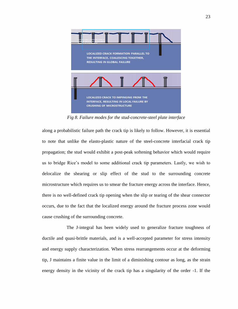
23
Fig 8. Failure modes for the stud-concrete-steel plate interface
along a probabilistic failure path the crack tip is likely to follow. However, it is essential
to note that unlike the elasto-plastic nature of the steel-concrete interfacial crack tip
propagation; the stud would exhibit a post-peak softening behavior which would require
us to bridge Rice’s model to some additional crack tip parameters. Lastly, we wish to
delocalize the shearing or slip effect of the stud to the surrounding concrete
microstructure which requires us to smear the fracture energy across the interface. Hence,
there is no well-defined crack tip opening when the slip or tearing of the shear connector
occurs, due to the fact that the localized energy around the fracture process zone would
cause crushing of the surrounding concrete.
The J-integral has been widely used to generalize fracture toughness of
ductile and quasi-brittle materials, and is a well-accepted parameter for stress intensity
and energy supply characterization. When stress rearrangements occur at the deforming
tip, J maintains a finite value in the limit of a diminishing contour as long, as the strain
energy density in the vicinity of the crack tip has a singularity of the order -1. If the
24
24
unloading of a specimen follows the identical stress-strain path as its loading phase, such
non-linear elastic behavior can be justified by the path independence of the J-Integral.
But, in this case, the material develops tension softening leading to growth of FPZ by
interlinking propagating crack flanks. The confusion in applying the J-integral to such
materials arises during evaluation of the contour surrounding the process zone, when the
unloading of the material defies the non-linear elastic assumption behind the basic J-
Integral formulation [23]. The issue is addressed by considering a contour remote
far from
the FPZ that passes through the concrete microstructure and the steel plate. Due to path
independence of the J-integral the contour pz
wrapped around the fracture process zone
possesses the same value as remote
. When the material enclosed by the process zone
unloads elastically with decreasing tensile traction and increasing crack opening (on the
line y=0) ; the material at the process zone(pz
, y=0+0) must also unload in order to
maintain equilibrium, which is elastic in nature and follows the traditional stress-strain
relationship [23]. The remote contour in conjunction with the contour wrapped around
the process zone allows us to determine the correlation between energy released and
supplied during tension softening. In our case, a bridging model seems feasible that
would result in a correction term, in addition to the integral; when the additional contour
wrapped around the crack tip shrinks, which is similar to the cohesive crack model.
J= K
2
tip(12)
E+
0
t
()d (23)
25
25
where, () describes the tension softening of the process zone; Ktip fracture toughness;
E Elastic modulus; Poisson’s ratio; δt: crack tip opening at end of the fracture process
zone. Critical value of the integral (J=Jcrit
) occurs when the traction free crack opening
t
crit corresponding to
crit=0. Energy consumed in the process zone is comparatively
greater than at the advancing crack tip. The empirical expression for () for concrete
under uniaxial tension was given by Stang et al.(1992)[50]
()=
u
m
1+
0
P
; σm, δp and δo are empirically determined
3.1.2 Application of J-Integral for crack path propagation due to slip of steel plate
We follow a similar procedure as applied to the steel plate concrete interface and try to
use the path independence property to avoid crack tip singularity by calculating stresses
and tractions along the remote contour, when the stud is exposed to slip forces. Three
possible integral paths can be defined for cracks propagating parallel to the interface
=LABCDEFGHIJKL ;defining the entire domain
C
=IJLKA=remote
;defining the far field integral path in concrete microstructure
S
=IAKMJ ;defining the integral path in steel
pz
=IHGFEDCBA; integral path in fracture process zone where crack originates and branches out
We can correlate the integral paths and incorporate the different phases of fracture
propagation using the expression
=remote/conc
+steel
stud
26
26
Fig 9. Integral paths defined at the process zone to capture inelastic tension softening
effects at stud-concrete-steel plate interface
Now, from the definition of J-integral, where 1 and
2 are smeared crack tip opening
parallel to the interface, we obtain (from Eq 7.3 obtained in Chapter.2)
Jconc/remote
=
conc
Wconcdy
conc
Tconc uconc
xdS ;SS
conc (15)
Jsteel
=
steel
Wsteeldy
steel
Tsteel usteel
xdS ;SS
steel (16)
Jstud
=
stud
Wstuddy
stud
Tstud ustud
xdS +
K2
tip(12)
E (17)
Using Eq 23; bridging the integral with crack tip correction term
(18)
27
27
Dissociating the integral for crack fronts CDE and HGF, we obtain
Jstud
=
CDE
()d1
+
HGF
()d2
stud
Tstud
u
stud
xdS +
K2
tip|CDE
(12
)
E+ +
K2
tip|HGF
(12
)
E (19)
The expression for process zone satisfies the stress and displacement continuity. The
singularity in the process zone due to tension softening is taken care of by the additional
crack tip term. However, it is important to observe that we are neglecting plasticity
effects at the crack tip as experiments have proven that the size of plastic zone during slip
of shear stud is meager compared to the softening phase.
3.2. Application of J-Integral for stud-microstructure interface due to pullout
When subjected to pullout forces the stud experiences local buckling at the connector-
steel plate-concrete interface and the crack is expected to follow a path propagating at an
angle from the crack tip causing local (micro-meso) failure and crushing at the base of
stud. The nature of failure is opposed to the scenario when the steel plate is subjected to
slip; where the cracks from stud tip branch out and coalesce resulting in a global (macro-
meso) failure and debonding of the concrete chunk (see Fig. 8).
The probable integral paths for cracks propagating at an angle of from the crack
tip can be defined as
=ahgfponmk
C =onml=
remote
S =hgfpolka
pz
=gjfedcbaih
28
28
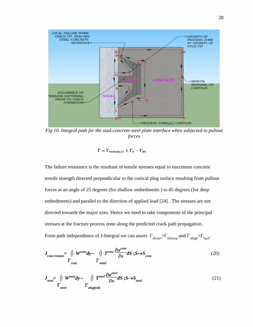
Fig 10. Integral path for the stud-concrete-steel plate interface when subjected to pullout
forces
The failure resistance is the resultant of tensile stresses equal to maximum concrete
tensile strength directed perpendicular to the conical plug surface resulting from pullout
forces at an angle of 25 degrees (for shallow embedments ) to 45 degrees (for deep
embedments) and parallel to the direction of applied load [24] . The stresses are not
directed towards the major axes. Hence we need to take components of the principal
stresses at the fracture process zone along the predicted crack path propagation.
From path independence of J-Integral we can assert abcdef
=klmnop
and aihgjf
=kpol
.
Jconc/remote
=
conc
Wconcdy
onml
Tconc uconc
xdS ;SS
conc (20)
Jsteel
=
steel
Wsteeldy
ahgfpolk
Tsteel usteel
xdS ;SS
steel (21)
29
29
Jstud
=
stud
Wstuddy
stud
Tstud ustud
xdS +
K2
tip(12)
E (22)
Using Eq 23; bridging the integral with crack tip correction term
(23)
Using the path dependence relations,
where 1 and
2 are smeared crack displacements and is angle of the crack to the
horizontal plane.
3.3. Size effect on fracture energy release into process zone
Bazant et al.[25] examined the quasi-brittle nature of shear connectors with post-peak
softening and also analyzed the size effect on nominal strength of composite beams.
However, it is expected that the post-peak softening will increase with the size of
stud[25]. Since the studs do not reach their maximum shear strength simultaneously, the
crack propagates parallel to the interface, which requires energy release analysis.
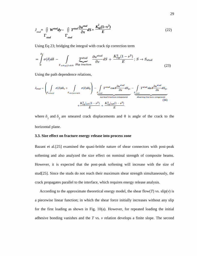
According to the approximate theoretical energy model, the shear flow(T) vs. slip(v) is
a piecewise linear function; in which the shear force initially increases without any slip
for the first loading as shown in Fig. 10(a). However, for repeated loading the initial
adhesive bonding vanishes and the T vs. v relation develops a finite slope. The second
30
30
line segment corresponds to a simplified linear incremental shear flow leading to a peak
value, the third represents post-peak softening. The tension softening also depends on the
size of plastic zone (see Fig 10(b)). The last phase depicts frictional slip at a constant
stress equivalent to the residual shear strength
Fig 11. (a)Idealized shear force-slip diagram for deformable connectors [18](b)Idealized
plastic zone formation and post peak tension softening
The post-peak decrease of stud force or softening localizes into a finite zone called the
fracture process zone. Also, the limit capacity is not reached simultaneously in all the
connectors as assumed in plastic analysis; but only to a limited group of connectors that
occupy a finite length. and propagates due to loading at the steel-concrete interface. Since,
softening is defined by stress-displacement relation rather than the stress-strain relation,
the crack length is approximately constant.
ν
31
31
3.4. Microstructural damage of the reinforcement-concrete interface when subjected
to pullout forces
The bond slip and anchorage length determination of reinforcement embedded in
concrete is a complex phenomenon. The ACI 318[26] code gives simple provisions for
defining the development length of reinforcing bars considering average bond resistance
over the entire anchored length, so that the bar can develop its complete yield capacity.
However, the anchorage length for a single bar and multiple bars vary owing to a weak
plane formation due to splitting cracks. The code also incorporates empirical correction
factors such as cb(smallest side cover), K
tr(contribution of confining reinforcement along
splitting planes), t(location factor); but doesn’t speak about the mechanics of debonding
and crack propagation at the interface level. Furthermore, the development length is
obtained on the basis of plastic shear slip behavior by equating the reinforcement yield
load (Fy=A
s*f
y) to bond strength (
c(2r)*L
s);
c being the critical shearing force and r, L
s
the radius and slip distance, respectively. A linear proportionality can be developed
between these parameters, concrete strength (f'c) and the tensile splitting strength (f'
t) as
cf'
t f'
c
from which the development Ld can be expressed as CA
sfy/ f'
c; C being an empirical
constant derived from experimental data.
The thesis tries to define a theory based on fundamental NLFM and EPFM concepts to
answer questions pertaining to the local and global failure modes of the interfacial rebar
fracture. Ingraffea et al.[27] used a cohesive non-linear fracture model to account for
tension softening behavior and concluded that secondary cracking emanating from the
32
32
primary cracks leads to slipping. Bazant et al.[28] used axis-symmetric formulations in
accordance with circumferential stress-strain relationship for a smeared cohesive model
to obtain a simplistic crack softening function.
This study tries to build a simplistic model of the rebar pullout phenomenon by
subdividing it into three zones based on interfacial parameters, aggregate interlock,
cohesion and formation of plastic and tension softening regions due to confined concrete.
Once again, the path independent J-Integral is used for obtaining the fracture energy
taking into consideration Li’s tension softening model[23] in conjunction with Bazant’s
strain-softening function[28].
3.4.1. Elasto-plastic fracture model for rebar specimen embedded in concrete
We divide the specimen into three primary zones as mentioned above according to their
failure criterion. Zone I represents the formation of conical plug at the pullout face while
Zone II depicts crushing where the concrete bears on steel ribs and Zone III represents
the crushing of confined concrete at the base. Ingraffea et.al[27] rightly asserted
secondary cracking to be the dominant mechanism contributing to slip. LEFM concepts
cannot be applied to short crack lengths associated with bond slip.
The Zone I crack is explained using Dugdale’s plasticity model. The expression for J-
Integral can be given by
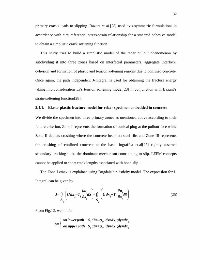
J=
S1
U dx2T
i u
i
xi
dS
S2
U dx2+T
i u
i
xi
dS (25)
From Fig.12, we obtain
S= on lower path S
1:T=
Y ds=dx
1;dy=dx
2
on upper path S2:T=+
Y ds=dx
1;dy=dx
2
33
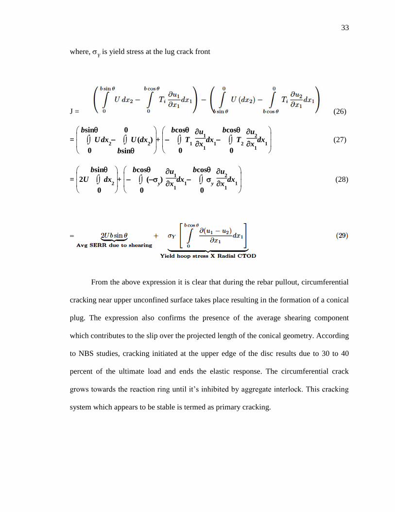
33
where, Y is yield stress at the lug crack front
J = (26)
=
0
bsin
U dx2
bsin
0
U (dx2) +
0
bcos
T1
u
1
x1
dx1
0
bcos
T2
u
2
x1
dx1
(27)
=
2U
0
bsin
dx2
+
0
bcos
(y) u
1
x1
dx1
0
bcos
y
u
2
x1
dx1
(28)
From the above expression it is clear that during the rebar pullout, circumferential
cracking near upper unconfined surface takes place resulting in the formation of a conical
plug. The expression also confirms the presence of the average shearing component
which contributes to the slip over the projected length of the conical geometry. According
to NBS studies, cracking initiated at the upper edge of the disc results due to 30 to 40
percent of the ultimate load and ends the elastic response. The circumferential crack
grows towards the reaction ring until it’s inhibited by aggregate interlock. This cracking
system which appears to be stable is termed as primary cracking.
34
34
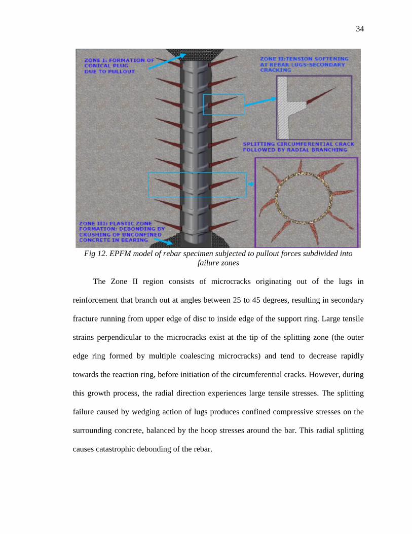
Fig 12. EPFM model of rebar specimen subjected to pullout forces subdivided into
failure zones
The Zone II region consists of microcracks originating out of the lugs in
reinforcement that branch out at angles between 25 to 45 degrees, resulting in secondary
fracture running from upper edge of disc to inside edge of the support ring. Large tensile
strains perpendicular to the microcracks exist at the tip of the splitting zone (the outer
edge ring formed by multiple coalescing microcracks) and tend to decrease rapidly
towards the reaction ring, before initiation of the circumferential cracks. However, during
this growth process, the radial direction experiences large tensile stresses. The splitting
failure caused by wedging action of lugs produces confined compressive stresses on the
surrounding concrete, balanced by the hoop stresses around the bar. This radial splitting
causes catastrophic debonding of the rebar.
35
35
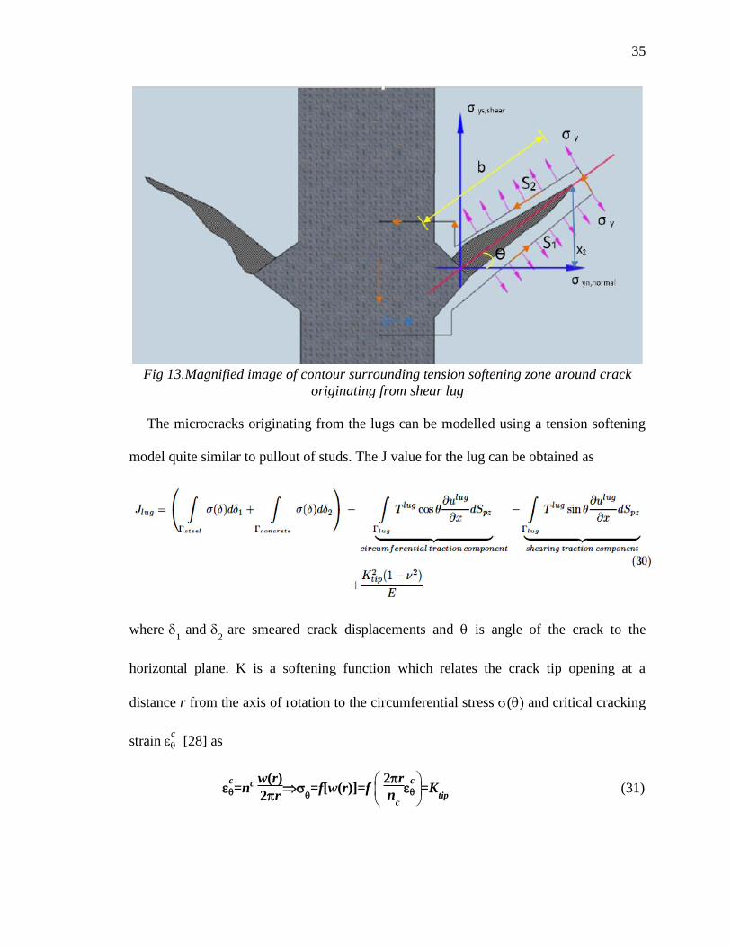
Fig 13.Magnified image of contour surrounding tension softening zone around crack
originating from shear lug
The microcracks originating from the lugs can be modelled using a tension softening
model quite similar to pullout of studs. The J value for the lug can be obtained as
where 1 and
2 are smeared crack displacements and is angle of the crack to the
horizontal plane. K is a softening function which relates the crack tip opening at a
distance r from the axis of rotation to the circumferential stress () and critical cracking
strain c
[28] as
c
=nc w(r)
2r
=f[w(r)]=f
2r
nc
c
=Ktip
(31)
36
36
where w(r) opening of each crack at distance r from axis of rotation, and nc number
of cracks.
Zone III represents a plastic zone formation due to crushing of surrounding confined
concrete. This stage is a consequence of the fracture growth and propagation in Zone II
III, and does not contribute to the slip primarily or secondarily.
Tepfers et al.[29] performed a simplified analysis of splitting cracks resulting from the
circumferential or normal stress() and related it to the interfacial shear stress() and
postulate a Coulomb-type failure criterion as
= tan (32)
is the constant complimentary friction angle valid for pseudo-static cases. This was
then modified by Rosati et al.[30] taking cohesion into consideration as
= (tan (33)
3.5. Constitutive elasto-plastic modelling for pseudo-static SSI
Micromechanical behavior at the granular media-structure interface is of major concern
as far as design of shallow and deep foundations, retaining structures, sheet piles, earth
reinforcements and other geotechnical structures are considered. The frictional
characteristics, failure planes and cohesion of soil have been studied through various
experimental, theoretical and constitutive models. The use of thin layered interface
elements had been proposed by Desai et al.[31], which is treated as a solid finite element
with its incremental stress-strain components linked by a constitutive stiffness matrix
consisting of normal and shear components as well as coupling effects. A variety of tests,
have been used to model the soil-structure interface. Fakharian[32] and Tejchman et
37
37
al.[33] performed modified direct and simple shear tests on sand steel interfaces to study
shear zone thicknesses and friction angles, when subjected to varied boundary conditions
under constant 2D and 3D normal stresses. Similar experiments were performed using
advanced imaging techniques[34] to account for failure modes during interface shearing
and sand particle deformation to understand strain hardening/softening and dilatancy
effects. Desai et al.[35] performed cyclic loading tests using CYMDOF(cyclic multi
degree of freedom device) which allowed for translational, normal and rotational motions
under direct and simple shear deformations for both drained and undrained laws.
Similarly, a large number of non-linear elastic, elasto-plastic, visco-elastic and
directional-type models have been proposed to model strength parameters and stress-
displacement relations which affect the load deformation behavior. Most of these models
use Mohr-Coulomb yield functions with incremental constitutive equations to define
empirical material parameters governing the displacements and stress distributions at
soil-structure interface. However, these empirical models cannot be generalized for all
types of soil media, which, being a multi-phase material depends greatly on interface
roughness, moisture content, particle size distribution. The different phases of soil-
structure interfaces when subjected to monotonic shearing and constant normal stresses
can be subdivided into: (i) intact phase: LEFM concepts can be applied during this stage.
During this phase the interface crack can be treated as a Griffith crack subjected to far
field stresses which can help us obtain asymptotic stress fields at the crack tip and
fracture toughness parameters. (ii) The critical phase (when the soil sample reaches it’s
maximum dilation or compressive state): The critical state is when the loose particles
interlock themselves in a state under which tangential displacement ceases to increase
38
38
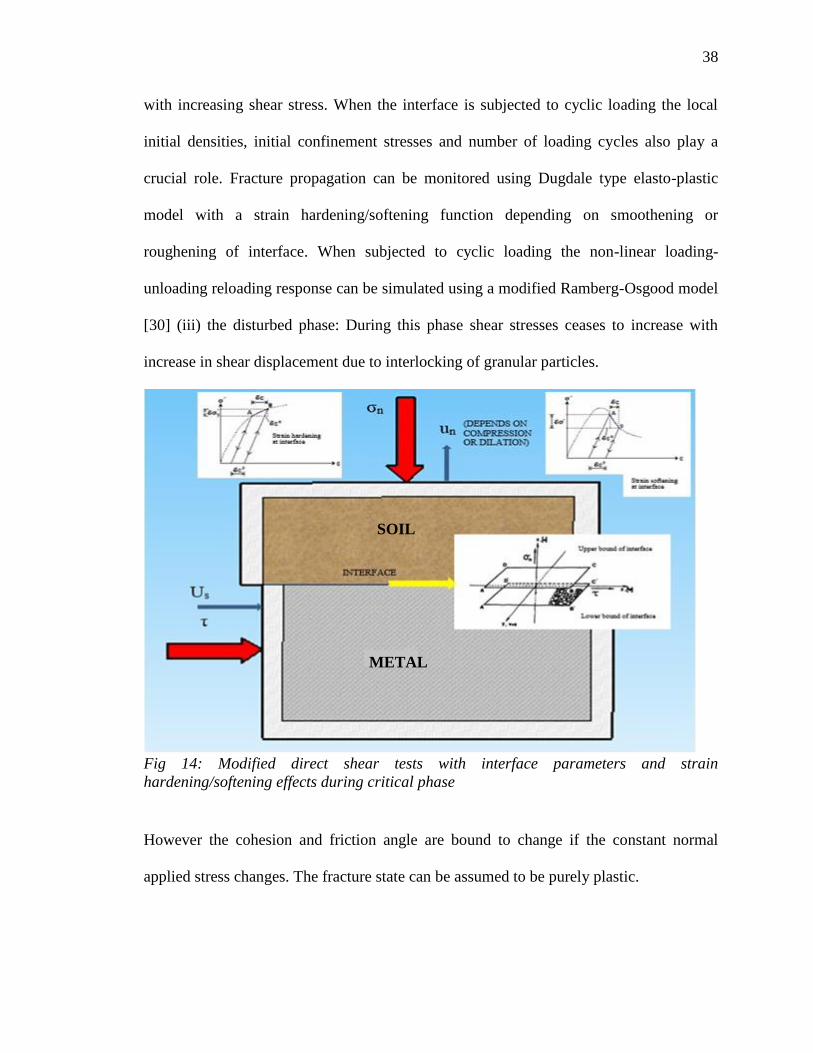
with increasing shear stress. When the interface is subjected to cyclic loading the local
initial densities, initial confinement stresses and number of loading cycles also play a
crucial role. Fracture propagation can be monitored using Dugdale type elasto-plastic
model with a strain hardening/softening function depending on smoothening or
roughening of interface. When subjected to cyclic loading the non-linear loading-
unloading reloading response can be simulated using a modified Ramberg-Osgood model
[30] (iii) the disturbed phase: During this phase shear stresses ceases to increase with
increase in shear displacement due to interlocking of granular particles.
Fig 14: Modified direct shear tests with interface parameters and strain
hardening/softening effects during critical phase
However the cohesion and friction angle are bound to change if the constant normal
applied stress changes. The fracture state can be assumed to be purely plastic.
SOIL
METAL

39
39
The proposed analytical model can be used for qualitative assessment of crack
propagation and impinging effects of modified direct shear tests that do not pre-define the
failure plane for granular media-structural interfaces, which is a scope of future studies.
40
40
CHAPTER 4. COMPUTATIONAL IMPLEMENTATION
The efficiency of computational methods for verification of the proposed analytical
model depends on the effective implementation of displacement discontinuities that do
not conform to inter-element surfaces. The proposed approach (as discussed in Chap. 2)
uses the conservation of energy principle for evaluation of crack initiation and growth in
a controlled volume. A similar energetic approach, the eXtended Finite Element Method
(XFEM) is adopted for modelling growth of a predefined crack front to analyze the strain
energy release rate (SERR) and stress intensity factors (SIF) assuming multiple contours
around the crack tip. XFEM uses the partition of unity approach to model strong and
weak discontinuities in a mesh-independent framework. This facilitates implementation
of discontinuous functions into a conventional finite element scheme by use of additional
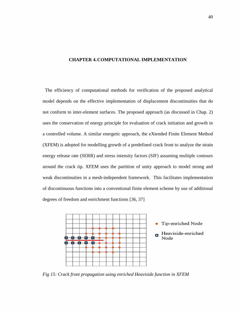
degrees of freedom and enrichment functions [36, 37]
Fig 15: Crack front propagation using enriched Heaviside function in XFEM
41
41
The enrichment functions are shifted such that they vanish at the nodes, since the nodal
displacement is a function of both the established and enriched DOF. Cracks are modeled
using a combination of two enrichment functions; one for the stress concentration at the
crack tip and a Heaviside step function to represent the discontinuity across the body of
the crack [38]. The Heaviside function accepts a value of 1 above the crack face and -1
below the crack, thus inserting a displacement discontinuity across the crack domain in
elements whose local support is cut by the crack.
(34)
where, r and ϴ are polar coordinates with origin at the crack tip and its principal axis
parallel to the crack face.
For the crack tip the enrichment functions shown above, were originally
introduced in the element-free Galerkin method [39] and later adopted for use in XFEM
[38]. These four functions span the crack tip displacement field. Upon solving the system
of equations, the enriched DOF’s can be used for interpolating within a particular element.
The enriched elements are able to handle strain discontinuities, significantly reducing the
pre-processing time that may arise due interface-mesh misalignment.
A model’s response contains large amount of tabulated data pertaining to its strain,
stress and displacement which is difficult to grasp as whole. Stress intensity factors help
in condensing the data, considerably reducing the complexity and post-processing
analysis time. The domain form of the contour interaction integral is used in the present
study to compute SIF’s along a static crack for steel-concrete and concrete-concrete
42
42
interface. The interaction integral involves superposition of auxiliary fields onto the
actual fields produced by the solution of a BVP.
4.1 ABAQUS implementation
ABAQUS [40] supports contour integral evaluations for an arbitrary stationary surface
crack without the need to conform the mesh to the geometry of the discontinuities.
Furthermore, only 1st order brick and 1st and 2
nd order tetrahedron elements with
isotropic elastic material configuration can be used for modelling stationary cracks. This
limits the scope of setting up benchmark models for validation of the analytical model.
However efforts have been made to set up individual models for analysis of SIF using
static cracks. The finite element model treats each contour as a ring of elements
surrounding the crack tip from one face to another, defined recursively to surround
previous contours [40]. Crack propagation across an interface is studied for a plane strain
block subjected to tensile forces using the cohesive segments approach, based on the
theory that substantial cohesive molecular forces exist near the crack-tip where two crack
surfaces are in close vicinity.
Intensity of the forces attain a maximum value when tensile strength of the
material is reached and starts to decrease as the crack faces start opening up. The region
between the point where the normal stress equals the tensile strength and the point at
which the crack opening displacement is equal to the critical opening, is called the
cohesive zone [41]. ABAQUS employs phantom nodes and cohesive segments for
ductile/brittle fracture governed by pressure overclosure relationship when crack is closed
and cohesive behavior contributes to normal contact stresses when crack is open. When
simulating XFEM cracks, it is essential to specify damage initiation criterion in the
43
43
material property definition. The maximum principal stress (MAXPS) criterion is
adopted for the benchmark models used in the current study.
Crack initiation also depends on the stress/strain concentrations in enriched nodes
and occurs when the max principal stress reaches a critical value (q=1) where q =
<σn>/σ0
max. The crack plane is perpendicular to the max principal stress and is capable of
handling a changed crack plane or direction of propagation. A damage evolution criterion
for traction separation law based on energy or displacement was used in conjunction with
the initiation criterion. As the crack grows along an interface, the structural response is
rendered non-linear or non-smooth making it difficult to attain convergence. Furthermore,
the crack feature in ABAQUS is limited to implicit analysis. Therefore, viscous
regularization was activated for convergence with the Newton method. The stabilization
value was chosen such that the response is unaffected while attaining convergence.
The major limitation associated with XFEM application to bimaterial interfacial
cracks, is associated with the crack definition itself. The assembly of a crack at the
junction of two independent material domains is not allowed. Hence, a single domain was
partitioned and the corresponding material properties were assigned to each partition. The
principal attraction of meshfree methods is their capacity to deal with moving boundaries
and discontinuities such as phase changes and crack propagation. Hence, the
XFEM_CRACK_ GROWTH interaction feature was used to analyze impinging
characteristics of a progressing crack front. This feature was switched off for evaluation
of stress intensity factors.
For crack tip visualization, stress field contours were requested for mode-II
loading of the uncracked domain. The output variables requested for crack tip simulation
44
44
of rectangular bi-material plate with an interfacial crack (will be discussed in next section)
are as follows:
PHILSM: Signed distance function describing crack surface
PSILSM: Signed distance function describing the initial crack front.
ENRRTXFEM: SERR components when XFEM is used for LEFM.
STATUSXFEM: Status of Heaviside enriched element. (1.0 if the element is
completely cracked and 0.0 if the element contains no crack)
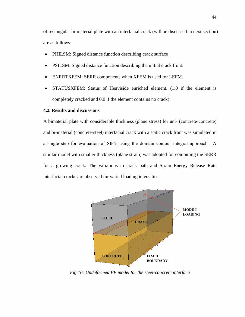
4.2. Results and discussions
A bimaterial plate with considerable thickness (plane stress) for uni- (concrete-concrete)
and bi-material (concrete-steel) interfacial crack with a static crack front was simulated in
a single step for evaluation of SIF’s using the domain contour integral approach. A
similar model with smaller thickness (plane strain) was adopted for computing the SERR
for a growing crack. The variations in crack path and Strain Energy Release Rate
interfacial cracks are observed for varied loading intensities.
Fig 16: Undeformed FE model for the steel-concrete interface
STEEL
CONCRETE
CRACK
MODE-I
LOADING
FIXED
BOUNDARY
45
45
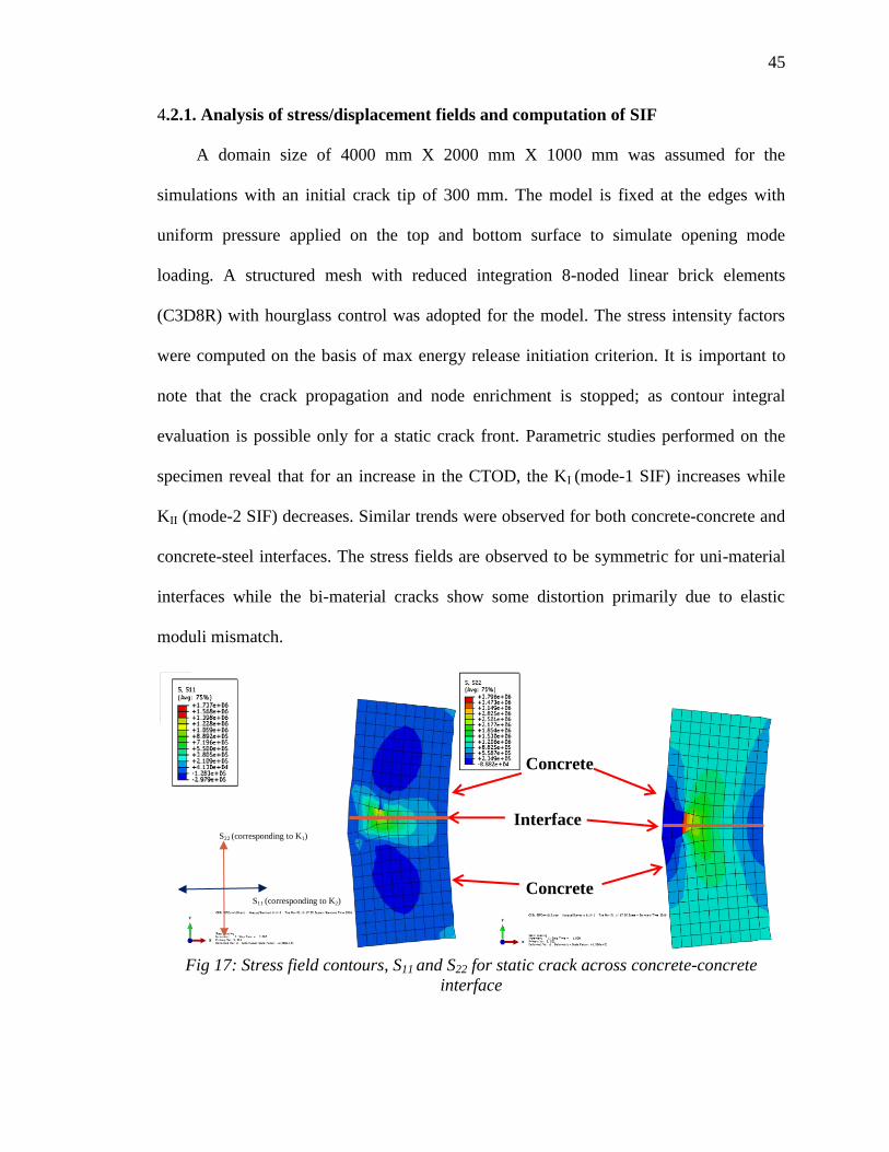
4.2.1. Analysis of stress/displacement fields and computation of SIF
A domain size of 4000 mm X 2000 mm X 1000 mm was assumed for the
simulations with an initial crack tip of 300 mm. The model is fixed at the edges with
uniform pressure applied on the top and bottom surface to simulate opening mode
loading. A structured mesh with reduced integration 8-noded linear brick elements
(C3D8R) with hourglass control was adopted for the model. The stress intensity factors
were computed on the basis of max energy release initiation criterion. It is important to
note that the crack propagation and node enrichment is stopped; as contour integral
evaluation is possible only for a static crack front. Parametric studies performed on the
specimen reveal that for an increase in the CTOD, the KI (mode-1 SIF) increases while
KII (mode-2 SIF) decreases. Similar trends were observed for both concrete-concrete and
concrete-steel interfaces. The stress fields are observed to be symmetric for uni-material
interfaces while the bi-material cracks show some distortion primarily due to elastic
moduli mismatch.
Fig 17: Stress field contours, S11 and S22 for static crack across concrete-concrete
interface
Concrete
Concrete
Interface S22 (corresponding to K1)
S11 (corresponding to K2)
46
46
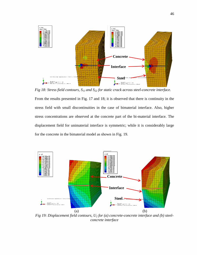
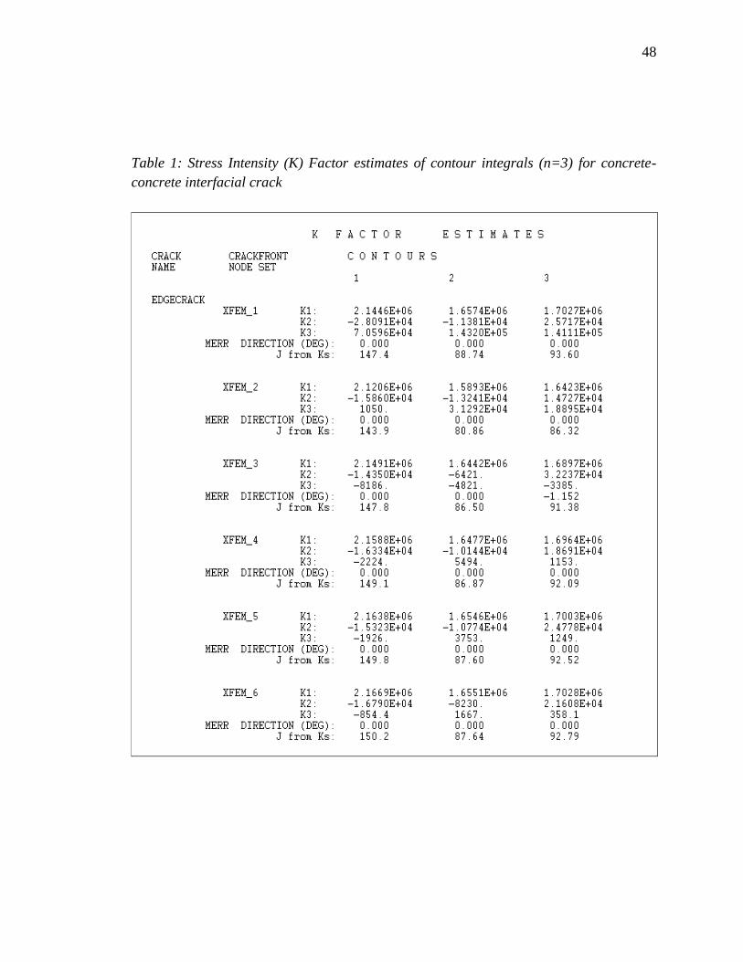
Fig 18: Stress field contours, S11 and S22 for static crack across steel-concrete interface.
From the results presented in Fig. 17 and 18; it is observed that there is continuity in the
stress field with small discontinuities in the case of bimaterial interface. Also, higher
stress concentrations are observed at the concrete part of the bi-material interface. The
displacement field for unimaterial interface is symmetric; while it is considerably large
for the concrete in the bimaterial model as shown in Fig. 19.
(a) (b)
Fig 19: Displacement field contours, U2 for (a) concrete-concrete interface and (b) steel-
concrete interface
Concrete
Steel
Interface
Concrete
Steel
Interface

47
47
The simulation results presented in Table 1 and 2, which gives the stress intensity factors
(K1, K2 and K3) and J estimates of three contours enclosing the crack tip for six time
increments of crack propagation along crack front propagation direction (MERR=0 deg).
It is observed that the normalized values of KI increases while KII decreases with the
increase of elastic modulus ratio, which are in agreement with the literature [42, 43].
Parametric studies also indicate that both K1 and K2 decrease with the increase in crack
tip opening. The analytical model highlights the fact that the J-Integral is a close measure
of the fracture energy of the cracked domain. Upon extending this idea to the XFEM
model for concrete-concrete interface; the fracture energy values were found to be quite
similar to those in literature derived empirically and from traction softening laws (ref.
Table 3). Furthermore, the J estimates for individual contours yielded nearly equivalent
data enforcing the path independent property. The J for the crack propagating along steel
concrete interface is considerably larger (around twice) than concrete-concrete interface;
which can be associated with plastic zone formation and evolution of residual energy.
48
48
Table 1: Stress Intensity (K) Factor estimates of contour integrals (n=3) for concrete-
concrete interfacial crack
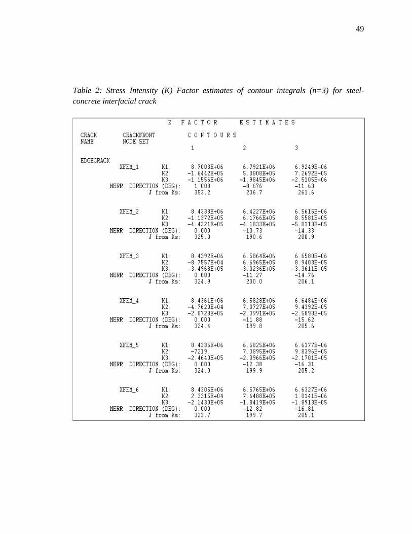
49
49
Table 2: Stress Intensity (K) Factor estimates of contour integrals (n=3) for steel-
concrete interfacial crack
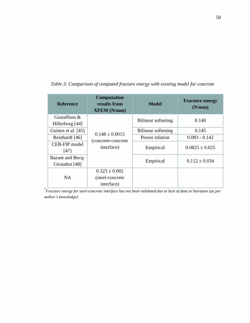
50
50
Table 3: Comparison of computed fracture energy with existing model for concrete
Reference
Computation
results from
XFEM (N/mm)
Model Fracture energy
(N/mm)
Gustaffson &
Hillerborg [44]
0.148 ± 0.0015
(concrete-concrete
interface)
Bilinear softening 0.140
Guinea et al. [45] Bilinear softening 0.145
Reinhardt [46] Power relation 0.083 - 0.142
CEB-FIP model
[47] Empirical 0.0825 ± 0.025
Bazant and Becq-
Giraudon [48] Empirical 0.112 ± 0.034
NA
0.323 ± 0.002
(steel-concrete
interface)
*Fracture energy for steel-concrete interface has not been validated due to lack of data in literature (as per
author’s knowledge)
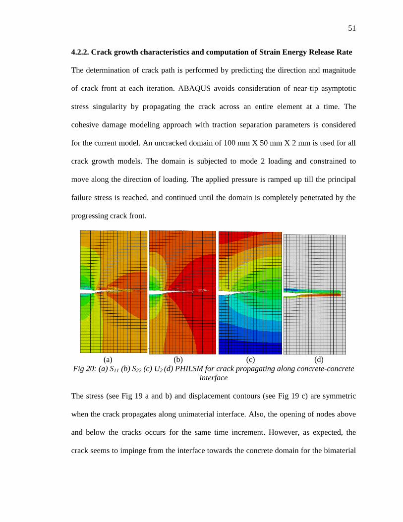
51
51
4.2.2. Crack growth characteristics and computation of Strain Energy Release Rate
The determination of crack path is performed by predicting the direction and magnitude
of crack front at each iteration. ABAQUS avoids consideration of near-tip asymptotic
stress singularity by propagating the crack across an entire element at a time. The
cohesive damage modeling approach with traction separation parameters is considered
for the current model. An uncracked domain of 100 mm X 50 mm X 2 mm is used for all
crack growth models. The domain is subjected to mode 2 loading and constrained to
move along the direction of loading. The applied pressure is ramped up till the principal
failure stress is reached, and continued until the domain is completely penetrated by the
progressing crack front.
(a) (b) (c) (d)
Fig 20: (a) S11 (b) S22 (c) U2 (d) PHILSM for crack propagating along concrete-concrete
interface
The stress (see Fig 19 a and b) and displacement contours (see Fig 19 c) are symmetric
when the crack propagates along unimaterial interface. Also, the opening of nodes above
and below the cracks occurs for the same time increment. However, as expected, the
crack seems to impinge from the interface towards the concrete domain for the bimaterial
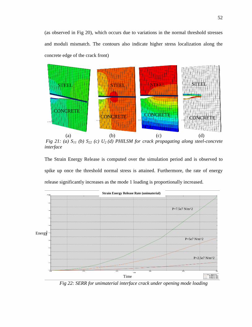
52
52
(as observed in Fig 20), which occurs due to variations in the normal threshold stresses
and moduli mismatch. The contours also indicate higher stress localization along the
concrete edge of the crack front)
(a) (b) (c) (d)
Fig 21: (a) S11 (b) S22 (c) U2 (d) PHILSM for crack propagating along steel-concrete
interface
The Strain Energy Release is computed over the simulation period and is observed to
spike up once the threshold normal stress is attained. Furthermore, the rate of energy
release significantly increases as the mode 1 loading is proportionally increased.
Fig 22: SERR for unimaterial interface crack under opening mode loading
P=7.5e7 N/m^2
P=5e7 N/m^2
P=2.5e7 N/m^2
Strain Energy Release Rate (unimaterial)
STEEL STEEL STEEL STEEL
CONCRETE
CONCRETE CONCRETE CONCRETE
Energy
Time
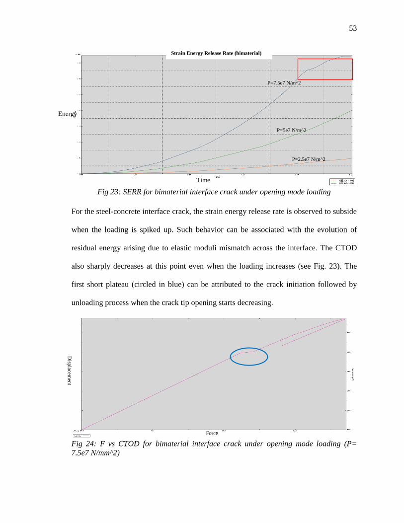
53
53
Fig 23: SERR for bimaterial interface crack under opening mode loading
For the steel-concrete interface crack, the strain energy release rate is observed to subside
when the loading is spiked up. Such behavior can be associated with the evolution of
residual energy arising due to elastic moduli mismatch across the interface. The CTOD
also sharply decreases at this point even when the loading increases (see Fig. 23). The
first short plateau (circled in blue) can be attributed to the crack initiation followed by
unloading process when the crack tip opening starts decreasing.
Fig 24: F vs CTOD for bimaterial interface crack under opening mode loading (P=
7.5e7 N/mm^2)
P=5e7 N/m^2
P=2.5e7 N/m^2
Force
Disp
lacemen
t
Strain Energy Release Rate (bimaterial)
P=7.5e7 N/m^2
Energy
Time

54
54
CHAPTER 5. CONCLUSIONS
A comprehensive energy-based approach was developed in the thesis to assess the
fracture toughness parameters pertaining to the fundamental failure modes of bimaterial
interfaces. The controlled volume fracture model was used (in Chap. 2) to correlate the
fracture energy released during crack growth to the potential energy of the entire system.
Using the conservation of energy principle, a suitable stress strain relation was derived in
terms of the strain energy released, which can be obtained from experimental data and
therefore allow us to calibrate the model. The potential energy release rate was obtained
for a contour surrounding the crack tip in terms of the strain energy release rate and
traction slip parameters. The J-integral was used to compute the strain energy release rate
and crack tip opening displacement. Path independence of the J-integral provides the
freedom to frame the boundary value problem for a domain where the stresses and
tractions are well defined. This allows us to bypass the numerical complexities associated
with computation of asymptotic stress fields. After some numerical analysis, The J-
integral was found to be the difference between the gross strain energy release rate
(SERR) and the tangential traction slip energy for bimaterial interface.
For a growing crack, the paradox is that when strains and stresses are singular but
their singularity is not strong enough to obtain a non-zero local energy release rate,
55
55
there is no energy surplus for crack production [49]. The model attributes the surplus
energy to plastic dissipation with probable strain hardening/softening. Plasticity effects at
the crack tip were addressed by adopting a boundary interface path surrounding the crack
tip assuming crack front yielding. The J-integral was linked to the crack tip opening
(CTOD); since evaluation of strain energy rate was not possible for an equivalent elastic
crack field corresponds to the ‘deformation theory of plasticity’. For small plastic
deformations, J was expressed as the product of the crack tip opening displacement
(CTOD) and the yield stress at the crack tip (σY) (see Sec 2.3).
The analytical model presented in Chap. 2 was applied to some common
bimaterial interfaces (the stud-microstructure-steel plate and rebar-concrete interface). A
crack front was assumed for each case depending on test data available in literature and
the contour integral paths were defined for each case such that individual material
properties and loading parameters can be used to formulate the problem statement.
Appropriate tension softening effects associated with the crack tip progression were
implemented using a correction term. The fracture toughness and stress intensity factors
were evaluated empirically. The different stages of microstructural failure of the rebar
concrete interface were analyzed. The strain energy values (in terms of J) can help us in
assessing the governing failure mode and provide valuable information about the damage
expansion phenomenon from micro to macro scale for structural elements.
There is some practical significance attached to the energy conservation approach, as it
helps develop an understanding of deterministic parameters irrespective of crack-tip
singularities and applied loading. The level of external loading responsible for imparting
instability to a pre-existent crack is difficult to obtain. Using XFEM techniques, the
56
56
contour integrals were evaluated at each node of the crack front (ref Chap.4). The
interfacial fracture energy of uni-material (concrete-concrete) interface was computed
from a XFEM static crack model. The results were in close agreement (variation of 10%-
15%) with existing analytical and empirical models in literature. Fracture energy
computed for the bimaterial (steel-concrete) interface was found to be twice that of
concrete-concrete interface (could not be verified due to lack of experimental data). The
SIF values were found to converge for individual contours conforming to the path
independence property. For a growing crack, the strain energy release rate was observed
to significantly increase with the increment of mode-1 loading applied on the domain.
The rate of increase for bimaterial interface was observed to be steeper than the
unimaterial interface as the loading was ramped up. As expected from the numerical
computation (ref. Sec 2.3), the model also showed impinging of the crack towards
concrete, due to lower elastic modulus.
Even though conformal meshing is not essential for modelling a discontinuity
using XFEM, it is difficult to achieve a good convergence rate and high accuracy for
problems with moving domain. Computational difficulties from domain dependence
arising due to variations in the approximate finite element solutions require continuous
mesh refinement. The model proposed is not suitable for cracks propagating at high strain
rates. Also, material discontinuities and incremental plasticities have not been accounted
for. The scaling of the model for macroscopic failure response of the structure in
accordance with size effect laws is a topic of future studies. However, with the use of
appropriate strain hardening/softening function, this model can be applied to a variety of

57
57
ductile-brittle interfaces with largely varying Young’s modulus, resulting in close formed
solutions for the strain energy release rate and crack tip opening displacements

BIBLIOGRAPHY
58
58
BIBLIOGRAPHY
[1]Rice, J. (1968). A Path Independent Integral and the Approximate Analysis of Strain
Concentration by Notches and Cracks. Journal of Applied Mechanics, 35(2), 379.
[2] Rybicki, E.F., & Kanninen, M.F. (1977). A finite element calculation of stress
intensity factors by a modified crack closure integral. Engineering Fracture
Mechanics, 9(4), 931-938.
[3] Darling, K., & U.S. Army Research Laboratory. (2011). Thermally stable nanometals
by predictive atomic scale interfacial energy reduction (ARL-TR (Aberdeen Proving
Ground, Md.) ; 5490). Aberdeen Proving Ground, Md.: Army Research Laboratory.
[4] Tuakta, C., & Büyüköztürk, O. (2011). Deterioration of FRP/concrete bond system
under variable moisture conditions quantified by fracture mechanics. Composites Part B:
Engineering, 42(2), 145-154.
[5]A.G. Evans, M. Rühle, B.J. Dalgleish, P.G. Charalambides, "The fracture energy of
bimaterial interfaces", Materials Science and Engineering: A, Volume 126, Issues 1–2, 15
June 1990, Pages 53-64
[6] M. L. Williams, “The stresses around a fault or crack in dissimilar media” Bulletin of
the Seismological Society of America (April 1959), 49(2):199-204
[7] Sih, G., & Rice, J. (1964). The Bending of Plates of Dissimilar Materials With
Cracks.Journal of Applied Mechanics, 31(3), 477.
59
59
[8] Rice, J., & Sih, G. (1965). Plane Problems of Cracks in Dissimilar Media. Journal
ofApplied Mechanics, 32(2), 418.
[9] Rice, J. (1988). Elastic Fracture Mechanics Concepts for Interfacial Cracks. Journal
of Applied Mechanics, 55(1), 98.
[10]Buyukozturk, Oral, Lee, Kwang-Myong. (1993)."Assessment of interfacial fracture
toughness in concrete composites". Cement and Concrete Composites, 15(3), 143-151.
[11]Dundurs, J. (1969). Discussion: “Edge-Bonded Dissimilar Orthogonal Elastic
Wedges Under Normal and Shear Loading” (Bogy, D. B., 1968, ASME J. Appl. Mech.,
35, pp. 460–466). Journal of Applied Mechanics, 36(3), 650.
[12]Buyukozturk, Oral, Hearing, Brian. (1998)."Crack propagation in concrete
composites influenced by interface fracture parameters". International Journal of Solids
and Structures, 35(31), 4055-4066.
[13]Bruhwiler, E., Wittmann, F.H. (1990). "The wedge splitting test, a new method of
performing stable fracture mechanics tests". Engineering Fracture Mechanics, 35(1), 117-
125.
[14]Walter, Rasmus, Ostergaard, Lennart, Olesen, John F., Stang, Henrik. (2005).
"Wedge splitting test for a steel–concrete interface". Engineering Fracture Mechanics,
72(17), 2565-2583.
[15] RILEM TC-108. Interfacial transition zone in concrete. RILEM Report 11. Chapman
and Hall, 1996.
[16] P.Ponte Castañeda, P.A. Mataga, Stable crack growth along a brittle/ductile
interface—I. Near-tip fields, International Journal of Solids and Structures, Volume 27,
Issue 1, 1991:105-133
60
60
[17] Bose, K. Ponte, P. Ponte Castañeda, and P. Ponte Mataga. "Stable Crack Growth
along a Brittle Ductile Interface - II. Small Scale Yielding Solutions and Interfacial
Toughness Predictions." International Journal of Solids and Structures 36.1 (1999): 1-34.
[18] Soh, C., Chiew, S., Dong, Y. (1999). "Damage Model for Concrete-Steel Interface".
Journal of Engineering Mechanics, 125(8), 979-983.
[19] Hutchinson, J. (1968). Singular behaviour at the end of a tensile crack in a hardening
material. Journal of the Mechanics and Physics of Solids, 16(1), 13-31.
[20] Dugdale, D. (1960). “Yielding of steel sheets containing slits”. Journal of the
Mechanics and Physics of Solids, 8(2), 100-104.
[21] Yuan, Huang, & Brocks, Wolfgang. (1991). On the J-integral concept for elastic-
plastic crack extension. Nuclear Engineering and Design, 131(2), 157-173.
[22] Shan-suo, Li Lei, Wang Bin.(2009)"Shear transmitting capacity of interface between
steel and concrete".Engineering Mechanics.Vol. 26, No.3,p.148
[23]Li, Victor C. (1997). "Applicability of J-integral to tension-softening materials".
Journal of Engineering Mechanics, 123(5), 531.
[24] Ballarini, R., Shah, S., & Keer, L. (1986). Failure Characteristics of Short Anchor
Bolts Embedded in a Brittle Material. Proceedings of the Royal Society of London. Series
A, Mathematical and Physical Sciences, 404(1826), 35-54.
[25]Bazant, Zdenek P., Vitek, Jan L. (1999). "Compound size effect in composite beams
with softening connectors".(part one: energy approach). Journal of Engineering
Mechanics, 125(11), 1308.
[26] ACI 318-14: Building code requirements for Structural concrete
61
61
[27]Ingraffea, A.R., Gerstle, W.H., Gergely, P., Saouma, V. (1984). Fracture mechanics
of bond in reinforced concrete: J. Struct. Division ASCE, Vol 110 No 4 (April 1984).
Computer-Aided Design, 16(6), 339
[28]Bazant, Z., Planas, J. (1998). Fracture and size effect in concrete and other
quasibrittle materials (New directions in civil engineering). Boca Raton: CRC Press.
[29]Tepfers, R., Chalmers Tekniska Hgskola. (1973)."A Theory of Bond Applied to
Overlapped Tensile Reinforcement Splices for Deformed Bars."
[30]Rosati, Modeling of Local Bar-to-Concrete Bond in RC ... to Practice, CEB-RTU,
Vol. 3, pg. 12.34-12.43, Riga, Latvia, October 1992. 97.
[31] Desai, C., Zaman, M., Lightner, J., & Siriwardane, H. (1984). Thin-layer element for
interfaces and joints. International Journal for Numerical and Analytical Methods in
Geomechanics, 8(1), 19-43.
[32] Fakharian, K., & Evgin, E. (2000). Elasto-plastic modelling of stress-path-dependent
behaviour of interfaces. International Journal For Numerical And Analytical Methods In
Geomechanics, 24(2), 183-199.
[33] Tejchman, J., & Wu, W. (1995). Experimental and numerical study of sand–steel
interfaces. International Journal for Numerical and Analytical Methods in
Geomechanics, 19(8), 513-536.
[34] Hu, Liming, & Pu, Jialiu. (2004). Testing and modeling of soil-structure
interface. Journal of Geotechnical and Geoenvironmental Engineering, 130(8), 851
[35] Desai, C., Drumm, E., & Zaman, M. (1985). Cyclic Testing and Modeling of
Interfaces. Journal of Geotechnical Engineering, 111(6), 793-815.
62
62
[36] Moes, N., Dolbow, J., Belytschko, T. (1999) "A finite element method for crack
growth without remeshing," International Journal for Numerical Methods in Engineering,
46, 131-150.
[37] Belytschko, T., Moes, N., Usui, S., Parimi, C. (2001) "Arbitrary discontinuities in
finite elements," International Journal for Numerical Methods in Engineering, 50, 993-
1013.
[38] Belytschko, T., Black, T. (1999) "Elastic crack growth in finite elements with
minimal remeshing," International Journal for Numerical Methods in Engineering, 45,
601-620.
[39] Fleming, M., Chu, A., Moran, B., Belytschko, T. (1997) "Enriched element-free
Galerkin methods for crack tip fields," International Journal for Numerical Methods in
Engineering, 40, 1483-1504.
[40] Abaqus 6.14 Online Documentation
[41] Barenblatt, G. (1962). The Mathematical Theory of Equilibrium Cracks in Brittle
Fracture. Advances in Applied Mechanics,7, 55-129.
[42] Miyakazi N, Ikeda T, Soda T, Munakata T (1993) Stress intensity factor analysis of
interface crack using boundary element method— application of contour-integral method.
Eng Frac Mech 45: 599–610
[43] Pathak, Himanshu, Singh, Akhilendra, & Singh, Indra. (2012). Numerical simulation
of bi-material interfacial cracks using EFGM and XFEM. International Journal of
Mechanics and Materials in Design, 8(1), 9-36.
63
63
[44] Gustafsson PJ, Hillerborg A. Improvements in concrete design achieved through the
application of fracture mechanics. In: Shah SP, editor. Application of fracture mechanics
to cementitious composites. Dordrecht, The Netherlands; 1985. p. 639–80.
[45] Guinea GV, Planas J, Elices M. A general bilinear fit for the softening curve of
concrete. Mater Struct 1994;27(2):99–105.
[46] Reinhardt HW. Crack softening zone in plain concrete under static loading. Cem
Concr Res 1985;15(1):42–52.
[47] Comite Euro-International du Beton-Federation Internationale de la Precontrainte.
CEB–FIP Model Code. Lausanne: Switzerland; 1991.
[48] Bazant ZP, Becq-Giraudon E. Statistical prediction of fracture parameters of
concrete and implications for choice of testing standard. Cem Concr Res 2001;32(4):529–
56.
[49] Rice, J R. (1978). Mechanics of quasi-static crack growth. United States. Retrieved
from http://www.osti.gov/scitech/servlets/purl/6428286
[50] Stang, Henrik, & Aarre, Tine. (1992). Evaluation of crack width in FRC with
conventional reinforcement. Cement and Concrete Composites, 14(2), 143-154.