DUCT MAIN ACCESSORIES - NTEICOnteico.com/wp-content/uploads/2015/10/Nteico-Duct-Accessories.pdfDUCT...
20
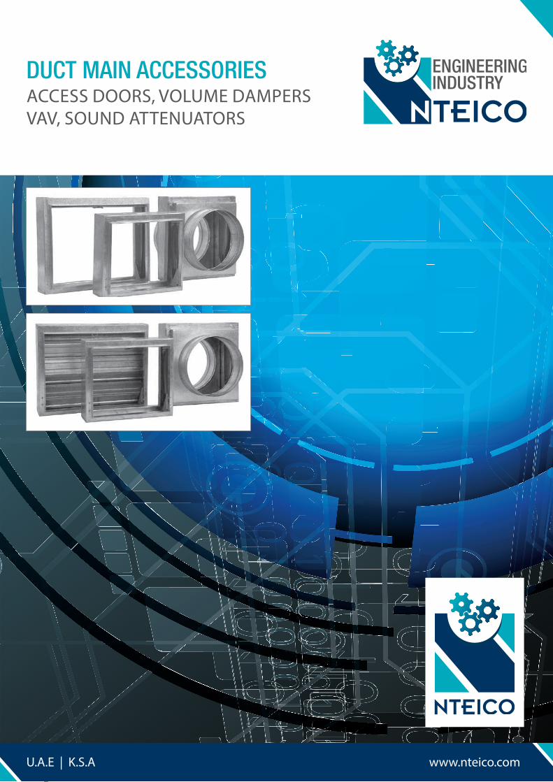
DUCT MAIN ACCESSORIES ACCESS DOORS, VOLUME DAMPERS VAV, SOUND ATTENUATORS www.nteico.com U.A.E | K.S.A
Transcript of DUCT MAIN ACCESSORIES - NTEICOnteico.com/wp-content/uploads/2015/10/Nteico-Duct-Accessories.pdfDUCT...
DUCT MAIN ACCESSORIESACCESS DOORS, VOLUME DAMPERSVAV, SOUND ATTENUATORS
www.nteico.comU.A.E | K.S.A
DUCT MAIN ACCESSORIESACCESS DOORS, VOLUME DAMPERS
VAV, SOUND ATTENUATORS

INDEX
ENGINEERING INDUSTRY
NTEICO VOLUME DAMPERS 07
NTEICO FIRE DAMPERS 13
NTEICO SOUND ATTENUATORS 17
NTEICO VARIABLE AIR VOLUME 16
NTEICO ACCESS DOORS 04
NTEICO DUCT MAIN ACCESSORIESACCESS DOORS
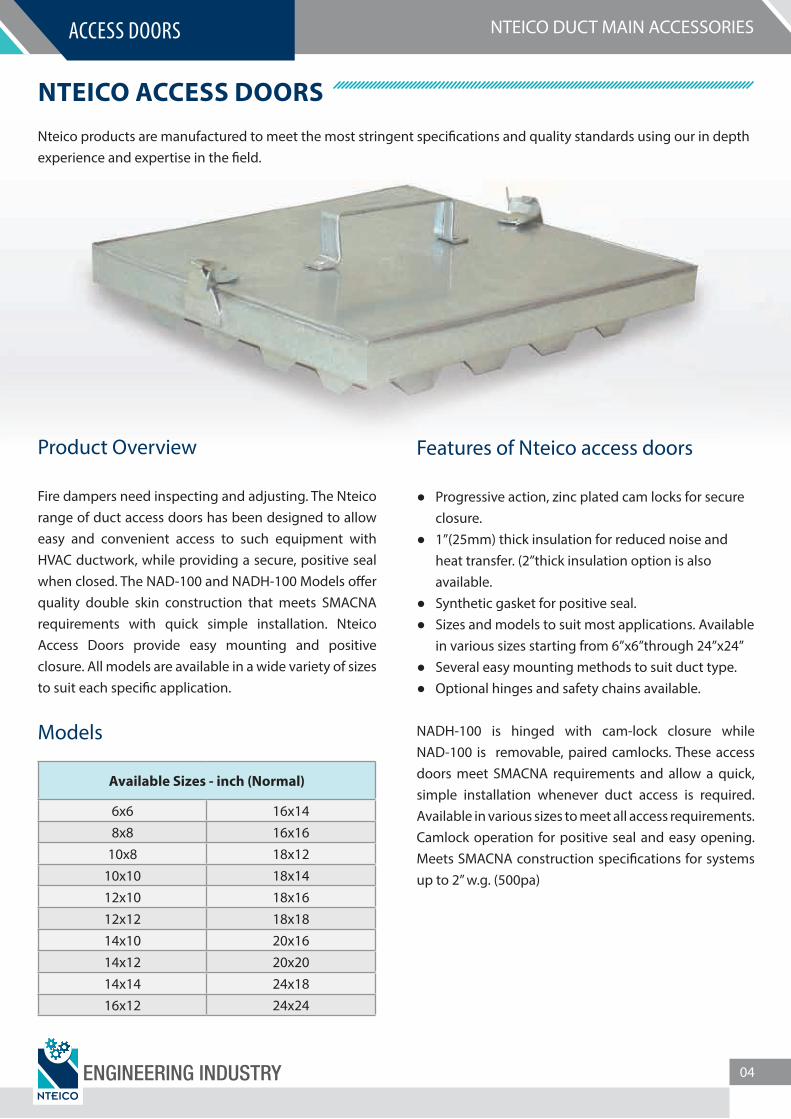
NTEICO ACCESS DOORSNteico products are manufactured to meet the most stringent speci�cations and quality standards using our in depthexperience and expertise in the �eld.
Product Overview
Fire dampers need inspecting and adjusting. The Nteico range of duct access doors has been designed to allow easy and convenient access to such equipment with HVAC ductwork, while providing a secure, positive seal when closed. The NAD-100 and NADH-100 Models o�er quality double skin construction that meets SMACNA requirements with quick simple installation. Nteico Access Doors provide easy mounting and positive closure. All models are available in a wide variety of sizes to suit each speci�c application.
Models
Available Sizes - inch (Normal)
6x6 16x148x8 16x16
10x8 18x1210x10 18x1412x10 18x1612x12 18x1814x10 20x1614x12 20x2014x14 24x1816x12 24x24
Features of Nteico access doors
Progressive action, zinc plated cam locks for secure closure.
1”(25mm) thick insulation for reduced noise and heat transfer. (2”thick insulation option is also available.
Synthetic gasket for positive seal. Sizes and models to suit most applications. Available
in various sizes starting from 6”x6”through 24”x24” Several easy mounting methods to suit duct type. Optional hinges and safety chains available.
NADH-100 is hinged with cam-lock closure while NAD-100 is removable, paired camlocks. These access doors meet SMACNA requirements and allow a quick, simple installation whenever duct access is required. Available in various sizes to meet all access requirements. Camlock operation for positive seal and easy opening. Meets SMACNA construction speci�cations for systems up to 2” w.g. (500pa)
ENGINEERING INDUSTRY 04
NTEICO DUCT MAIN ACCESSORIESACCESS DOORS
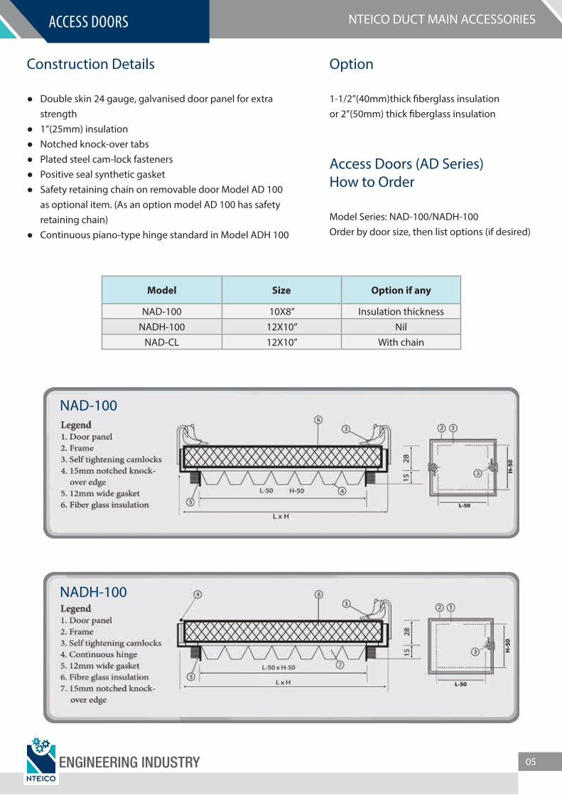
Construction Details
Double skin 24 gauge, galvanised door panel for extra strength
1”(25mm) insulation Notched knock-over tabs Plated steel cam-lock fasteners Positive seal synthetic gasket Safety retaining chain on removable door Model AD 100
as optional item. (As an option model AD 100 has safety retaining chain)
Continuous piano-type hinge standard in Model ADH 100
Option
1-1/2”(40mm)thick �berglass insulationor 2”(50mm) thick �berglass insulation
Access Doors (AD Series)How to Order
Model Series: NAD-100/NADH-100Order by door size, then list options (if desired)
Model Size Option if any
NAD-100 10X8” Insulation thicknessNADH-100 12X10” Nil
NAD-CL 12X10” With chain
NAD-100
NADH-100
ENGINEERING INDUSTRY 05

NTEICO DUCT MAIN ACCESSORIESACCESS DOORS
ACCESS DOORS PROJECTS EXECUTED
S.No. Project Consultants Location
01 Industrial City Labour 5 & 6 Meecon Dubai
02 Training Tracks 1 Project, Nad Al Sheba Teo A. Khing Design Consultants Dubai
03 Prudential Tower I&II, Al Tajir Real Estate, Jumeirah Village Ramboll-whitby & Bird Dubai
04 Post Contract Services Psuad Obermeyer Abu Dhabi
05 3B+G+HC+4 4 Comm/Resi Bldgs on Jumeirah Lake Tower L2 Eng. Adnan Sa�arini Dubai
06 Burj Dubai Development the Old Town Sites A&b D B A Architects International Dubai
07 Al Fattan Tower on Plot no GB-02 at DIFC C R K Dubai
08 Administrative Building in the Presidential Palace Altorath Eng. Consultants Abu Dhabi
09 Meydan Racing District Development Teo A. Khing Design Consultants Dubai
10 Discovery Gardens Projects ECG Dubai
11 Jumeirah Golf Estates Laing O’rourke Dubai
12 Jumeirah Village (Triangle) Villas & Townhouses Zone 1 Dynamic Engineering Consultant Dubai
13 G+6P+HC+25 Typical Floors Tower on Plot No 585 Horizon Al Nahda
14 International City Jap 015/4-15 Res/Comm Building Package 15 ACE Dubai
15 Remraam Main Building Work Phase 3 Conin Dubai
16 Nad Al Sheba Racecourse on Parcel Id 600-6888 Teo A. Khing Design Consultants Dubai
17 Meydan Business Park Package M 31 Building Teo A. Khing Design Consultants Dubai
18 G+2 Accommodation Building 01-017 at Dubai Silicon Oasis Shadid Engineering Consultant Dubai
19 3B+G+M+16+HC On Plot No 125-170 Riggat Al Buteen Eng. Adnan Sa�arini Dubai
20 Al Ain Resort and Water Park Khatib & Alami Al Ain
21 B+G+14(4 Buildings) Sports City National Engineering Bureau Dubai
22 UAE New University Campus G H D Al Ain
23 Ritz Carlton Hotel & Apartments Project Hyder Dubai
24 Ladies Sports Hall, Al Dhaid C A B Consultant Sharjah
25 Labour City 5 & 6 at Dubai Industrial City Meecon Dubai
26 Indian Social & Cultural Centre on Plot No P 17 Sector E14/01 Dastur Consultants Abu Dhabi
27 Beach Front Residential Development Dewan Dubai
28 Canal Residence West Plot No R8-14(Plot No 682-1402)Sports City Engineering Consultants Group Dubai
29 Royal Amvaj, Palm Jumeirah PJSI Dubai
ENGINEERING INDUSTRY 06
NTEICO DUCT MAIN ACCESSORIESVOLUME DAMPERS
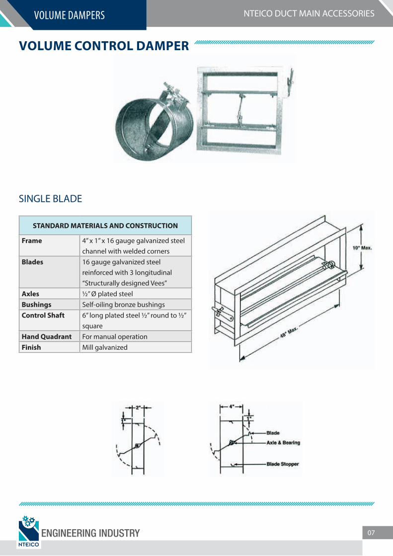
VOLUME CONTROL DAMPER
STANDARD MATERIALS AND CONSTRUCTION
Frame 4” x 1” x 16 gauge galvanized steel channel with welded corners
Blades 16 gauge galvanized steel reinforced with 3 longitudinal “Structurally designed Vees”
Axles ½” Ø plated steelBushings Self-oiling bronze bushingsControl Shaft 6” long plated steel ½” round to ½”
squareHand Quadrant For manual operationFinish Mill galvanized
SINGLE BLADE
ENGINEERING INDUSTRY 07
NTEICO DUCT MAIN ACCESSORIESVOLUME DAMPERS
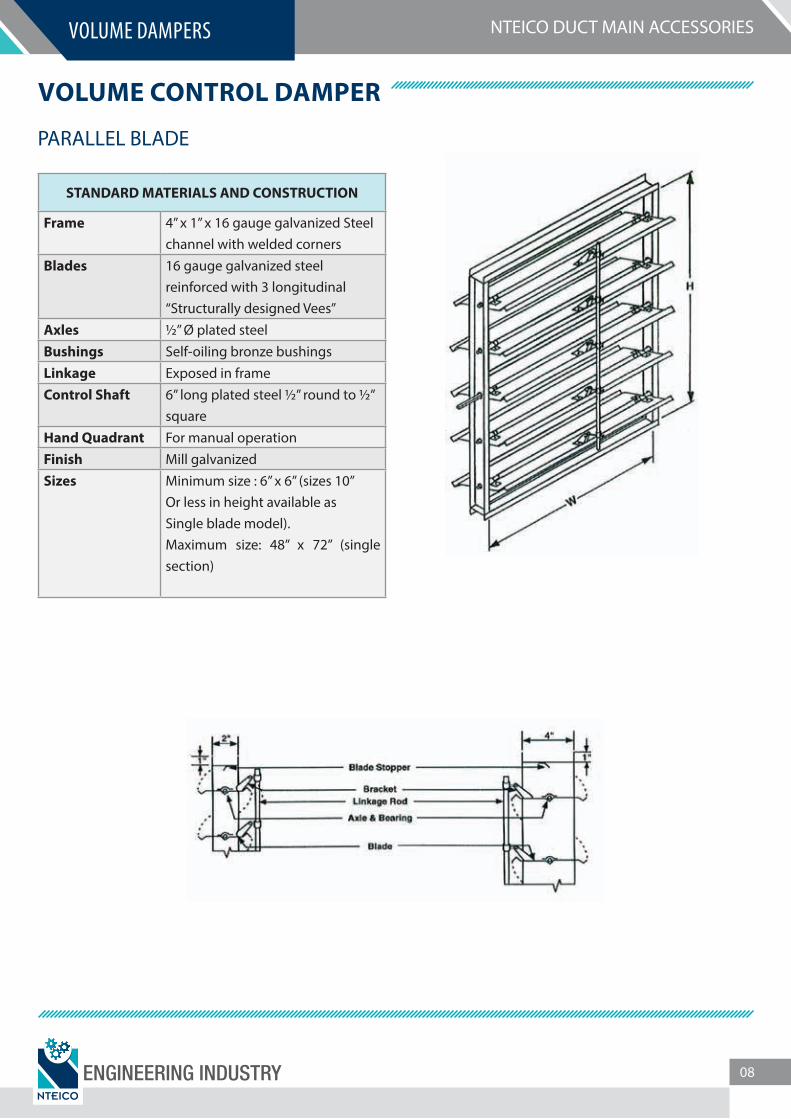
VOLUME CONTROL DAMPER
PARALLEL BLADE
STANDARD MATERIALS AND CONSTRUCTION
Frame 4” x 1” x 16 gauge galvanized Steel channel with welded corners
Blades 16 gauge galvanized steel reinforced with 3 longitudinal “Structurally designed Vees”
Axles ½” Ø plated steelBushings Self-oiling bronze bushingsLinkage Exposed in frameControl Shaft 6” long plated steel ½” round to ½”
squareHand Quadrant For manual operationFinish Mill galvanizedSizes Minimum size : 6” x 6” (sizes 10”
Or less in height available as Single blade model).Maximum size: 48” x 72” (single section)
ENGINEERING INDUSTRY 08
NTEICO DUCT MAIN ACCESSORIESVOLUME DAMPERS
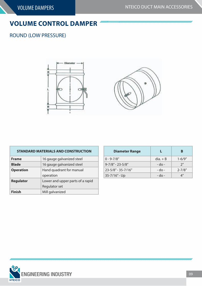
VOLUME CONTROL DAMPER
ROUND (LOW PRESSURE)
STANDARD MATERIALS AND CONSTRUCTION
Frame 16 gauge galvanized steelBlade 16 gauge galvanized steelOperation Hand quadrant for manual
operationRegulator Lower and upper parts of a rapid
Regulator setFinish Mill galvanized
Diameter Range L B
0 - 9-7/8” dia. + B 1-6/9”9-7/8” - 23-5/8” - do - 2”23-5/8” - 35-7/16” - do - 2-7/8”35-7/16” - Up - do - 4”
ENGINEERING INDUSTRY 09
NTEICO DUCT MAIN ACCESSORIESVOLUME DAMPERS
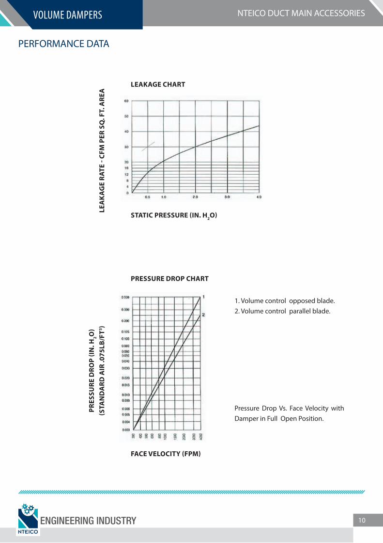
PERFORMANCE DATA
LEAKAGE CHART
PRESSURE DROP CHART
PRES
SURE
DRO
P (I
N. H
2O)
(STA
ND
ARD
AIR
.075
LB/F
T3 )
FACE VELOCITY (FPM)
1. Volume control opposed blade.2. Volume control parallel blade.
Pressure Drop Vs. Face Velocity with Damper in Full Open Position.
STATIC PRESSURE (IN. H2O)
LEA
KA
GE
RAT
E - C
FM P
ER S
Q. F
T. A
REA
ENGINEERING INDUSTRY 10
NTEICO DUCT MAIN ACCESSORIESVOLUME DAMPERS
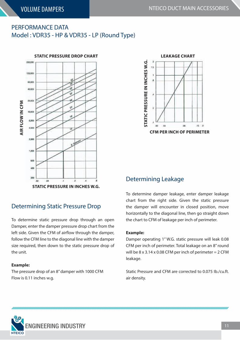
PERFORMANCE DATAModel : VDR35 - HP & VDR35 - LP (Round Type)
Determining Static Pressure Drop
To determine static pressure drop through an open Damper, enter the damper pressure drop chart from the left side. Given the CFM of air�ow through the damper, follow the CFM line to the diagonal line with the damper size required, then down to the static pressure drop of the unit.
Example:The pressure drop of an 8” damper with 1000 CFMFlow is 0.11 inches w.g.
Determining Leakage
To determine damper leakage, enter damper leakage chart from the right side. Given the static pressure the damper will encounter in closed position, move horizontally to the diagonal line, then go straight down the chart to CFM of leakage per inch of perimeter.
Example:Damper operating 1” W.G. static pressure will leak 0.08 CFM per inch of perimeter. Total leakage on an 8” round will be 8 x 3.14 x 0.08 CFM per inch of perimeter = 2 CFM leakage.
Static Pressure and CFM are corrected to 0.075 Ib./cu.ft. air density.
STATIC PRESSURE DROP CHART
STATIC PRESSURE IN INCHES W.G.
STAT
IC P
RESS
URE
IN IN
CHES
W.G
.
CFM PER INCH OF PERIMETERAIR
FLO
W IN
CFM
LEAKAGE CHART
ENGINEERING INDUSTRY 11
NTEICO DUCT MAIN ACCESSORIESVOLUME DAMPERS
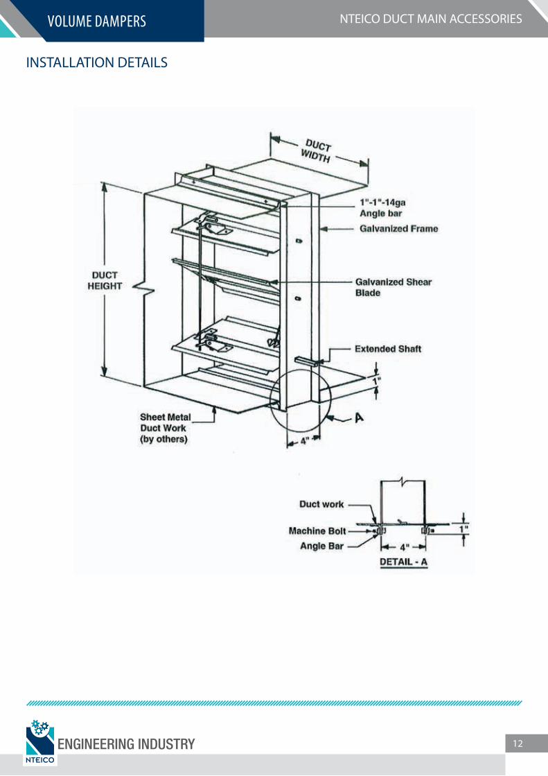
INSTALLATION DETAILS
ENGINEERING INDUSTRY 12
NTEICO DUCT MAIN ACCESSORIESFIRE DAMPER
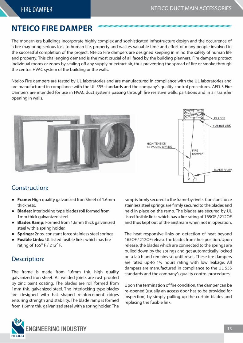
NTEICO FIRE DAMPERThe modern era buildings incorporate highly complex and sophisticated infrastructure design and the occurrence of a �re may bring serious loss to human life, property and wastes valuable time and e�ort of many people involved in the successful completion of the project. Nteico Fire dampers are designed keeping in mind the safety of human life and property. This challenging demand is the most crucial of all faced by the building planners. Fire dampers protect individual rooms or zones by sealing o� any supply or extract air, thus preventing the spread of �re or smoke through the central HVAC system of the building or the walls.
Nteico Fire dampers are tested by UL laboratories and are manufactured in compliance with the UL laboratories and are manufactured in compliance with the UL 555 standards and the company’s quality control procedures. AFD-3 Fire Dampers are intended for use in HVAC duct systems passing through �re resistive walls, partitions and in air transfer opening in walls.
Construction:
Frame: High quality galvanized Iron Sheet of 1.6mm thickness.
Blades: Interlocking type blades roll formed from 1mm thick galvanized steel.
Blades Ramp: Formed from 1.6mm thick galvanized steel with a spring holder.
Springs: 2nos. constant force stainless steel springs. Fusible Links: UL listed fusible links which has �re
rating of 165O F / 212O F.
Description:
The frame is made from 1.6mm thk. high quality galvanized iron sheet. All welded joints are rust proofed by zinc paint coating. The blades are roll formed from 1mm thk. galvanized steel. The interlocking type blades are designed with hat shaped reinforcement ridges ensuring strength and stability. The blade ramp is formed from 1.6mm thk. galvanized steel with a spring holder. The
ramp is �rmly secured to the frame by rivets. Constant force stainless steel springs are �rmly secured to the blades and held in place on the ramp. The blades are secured by UL listed fusible links which has a �re rating of 165OF / 212OF and thus kept out of the airstream when not in operation.
The heat responsive links on detection of heat beyond 165OF / 212OF release the blades from their position. Upon release, the blades which are connected to the springs are pulled down by the springs and get automatically locked on a latch and remains so until reset. These �re dampers are rated up-to 1½ hours rating with low leakage. All dampers are manufactured in compliance to the UL 555 standards and the company’s quality control procedures.
Upon the termination of �re condition, the damper can be re-opened (usually an access door has to be provided for inspection) by simply pulling up the curtain blades and replacing the fusible link.
ENGINEERING INDUSTRY 13

NTEICO DUCT MAIN ACCESSORIES
Installation Instructions
Sleeve:Dampers sleeve must be minimum 16 gauge (1.6mm) up-to maximum 10 gauge (3.5mm) steel. Sleeve thickness must be thicker than the duct connected to it. Sleeve gauge should comply with the SMACNA Duct Connection Standard Fire, Smoke and Radiation Damper Installation Guide for HVAC Systems and with NFPA90A. Sleeves must terminate on both sides of the wall within the dimension shown in (Fig.3, Fig.4).
Damper must be secured inside the sleeve by 1”x1”14-guage GI sub-frame, and the sub-frame to be fastened to sleeve by 5mm steel rivets or M5 bolts spaced at 150mm at the center and 50mm from the corners.
Duct-Sleeve Connections:The connecting ducts shall not be continuous, and shall terminate at the sleeve.Duct – Sleeve connections listed in UL555 STANDARD FOR FIRE DAMPERS.
Fasteners may be used follows(a) Joints using connections shown in (Fig.1) with a maximum of two #10 sheet metal screws on each side and on the bottom located in the center of the slip pocket and penetrating both sides of the slip pocket. (b) Joints using connectors of the type shown in (Fig.1) on the top and the bottom and using �at drive slips (Fig.2) not exceeding 508mm duct height on the sides.
Retaining Angle:Angle must be minimum 1½” x 1½”x14 gauge (38x38x2mm) steel and must overlap wall opening 1” (25mm) minimum and cover corners of openings. Retaining angles must be provided on both sides of the wall. Angles are fastened to sleeve by either M5 bolts or 5mm dia 20mm long steel rivets spaced at a maximum of 150mm at the centre and 50mm from the end. Retaining angles must not be �xed to each other or to the wall.
Damper Orientation:Vertical and Horizontal
Expansion Clearance:Fire damper sleeve clearance within wall opening must be ¼” larger than the damper size for damper sizes up to 24” and additional 1/8” per linear foot increase in the size of the damper.
Maximum rated size (Single Section):Vertical: 27” Width x 41” Height (672 x 1026mm)Horizontal: 36” Width x 36” Height (914.4 x 914.4mm)
Air�ow:Direction of air�ow is indicated by the arrow on the damper. The “AIR FLOW” direction arrow must be adhered to during installation.
Access Door:An ACCESS DOOR is a NFPA requirement for damper inspection and testing.
Fusible Link:Vertical: UL Listed 165OF / 212OF fusible link as standard.Horizontal: UL Listed 165OF fusible link as standard.
Fig. 3 Vertical Installation
Fig. 4 Horizontal Installation
FIRE DAMPER
ENGINEERING INDUSTRY 14
NTEICO DUCT MAIN ACCESSORIES
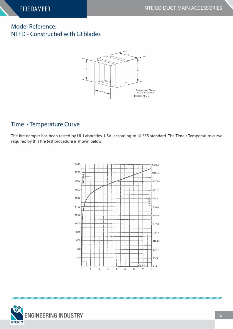
Model Reference:NTFD - Constructed with GI blades
Time - Temperature Curve
The �re damper has been tested by UL Laboraties, USA. according to UL555 standard. The Time / Temperature curve required by this �re test procedure is shown below.
FIRE DAMPER
ENGINEERING INDUSTRY 15
NTEICO DUCT MAIN ACCESSORIESVARIABLE AIR VOLUME
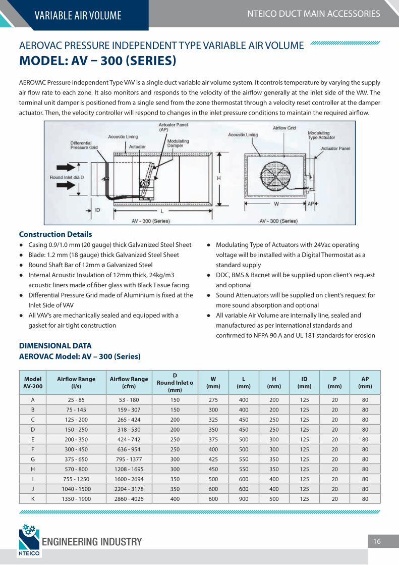
AEROVAC PRESSURE INDEPENDENT TYPE VARIABLE AIR VOLUMEMODEL: AV – 300 (SERIES)AEROVAC Pressure Independent Type VAV is a single duct variable air volume system. It controls temperature by varying the supply air �ow rate to each zone. It also monitors and responds to the velocity of the air�ow generally at the inlet side of the VAV. The terminal unit damper is positioned from a single send from the zone thermostat through a velocity reset controller at the damper actuator. Then, the velocity controller will respond to changes in the inlet pressure conditions to maintain the required air�ow.
Construction Details Casing 0.9/1.0 mm (20 gauge) thick Galvanized Steel Sheet Blade: 1.2 mm (18 gauge) thick Galvanized Steel Sheet Round Shaft Bar of 12mm ø Galvanized Steel Internal Acoustic Insulation of 12mm thick, 24kg/m3
acoustic liners made of �ber glass with Black Tissue facing Di�erential Pressure Grid made of Aluminium is �xed at the
Inlet Side of VAV All VAV’s are mechanically sealed and equipped with a
gasket for air tight construction
Modulating Type of Actuators with 24Vac operating voltage will be installed with a Digital Thermostat as a standard supply
DDC, BMS & Bacnet will be supplied upon client’s request and optional
Sound Attenuators will be supplied on client’s request for more sound absorption and optional
All variable Air Volume are internally line, sealed and manufactured as per international standards and con�rmed to NFPA 90 A and UL 181 standards for erosion
DIMENSIONAL DATAAEROVAC Model: AV – 300 (Series)
ModelAV-200
Air�ow Range(l/s)
Air�ow Range(cfm)
DRound Inlet o
(mm)
W(mm)
L(mm)
H(mm)
ID(mm)
P(mm)
AP(mm)
A 25 - 85 53 - 180 150 275 400 200 125 20 80
B 75 - 145 159 - 307 150 300 400 200 125 20 80
C 125 - 200 265 - 424 200 325 450 250 125 20 80
D 150 - 250 318 - 530 200 350 450 250 125 20 80
E 200 - 350 424 - 742 250 375 500 300 125 20 80
F 300 - 450 636 - 954 250 400 500 300 125 20 80
G 375 - 650 795 - 1377 300 425 550 350 125 20 80
H 570 - 800 1208 - 1695 300 450 550 350 125 20 80
I 755 - 1250 1600 - 2694 350 500 600 400 125 20 80
J 1040 - 1500 2204 - 3178 350 600 600 400 125 20 80
K 1350 - 1900 2860 - 4026 400 600 900 500 125 20 80
ENGINEERING INDUSTRY 16
NTEICO DUCT MAIN ACCESSORIESSOUND ATTENUATORS
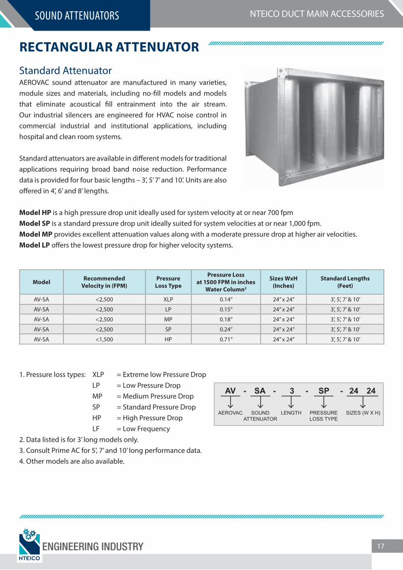
RECTANGULAR ATTENUATOR
Standard AttenuatorAEROVAC sound attenuator are manufactured in many varieties, module sizes and materials, including no-�ll models and models that eliminate acoustical �ll entrainment into the air stream. Our industrial silencers are engineered for HVAC noise control in commercial industrial and institutional applications, including hospital and clean room systems.
Standard attenuators are available in di�erent models for traditional applications requiring broad band noise reduction. Performance data is provided for four basic lengths – 3’, 5’ 7’ and 10’. Units are also o�ered in 4’, 6’ and 8’ lengths.
Model HP is a high pressure drop unit ideally used for system velocity at or near 700 fpmModel SP is a standard pressure drop unit ideally suited for system velocities at or near 1,000 fpm.Model MP provides excellent attenuation values along with a moderate pressure drop at higher air velocities.Model LP o�ers the lowest pressure drop for higher velocity systems.
Model RecommendedVelocity in (FPM)
PressureLoss Type
Pressure Lossat 1500 FPM in inches
Water Column2
Sizes WxH(Inches)
Standard Lengths(Feet)
AV-SA <2,500 XLP 0.14” 24” x 24” 3’, 5’, 7’ & 10’
AV-SA <2,500 LP 0.15” 24” x 24” 3’, 5’, 7’ & 10’
AV-SA <2,500 MP 0.18” 24” x 24” 3’, 5’, 7’ & 10’
AV-SA <2,500 SP 0.24” 24” x 24” 3’, 5’, 7’ & 10’
AV-SA <1,500 HP 0.71” 24” x 24” 3’, 5’, 7’ & 10’
1. Pressure loss types: XLP = Extreme low Pressure Drop LP = Low Pressure Drop MP = Medium Pressure Drop SP = Standard Pressure Drop HP = High Pressure Drop LF = Low Frequency2. Data listed is for 3’ long models only.3. Consult Prime AC for 5’, 7’ and 10’ long performance data.4. Other models are also available.
AV - - - -
AEROVAC SOUNDATTENUATOR
LENGTH PRESSURELOSS TYPE
SIZES (W X H)
SA 3 SP 24 24
ENGINEERING INDUSTRY 17

NTEICO DUCT MAIN ACCESSORIESSOUND ATTENUATORS
Special features of our Standard Attenuators are:
Di�usion angle to improve pressure drop. Bellmouth entrance to help minimize turbulence. 22 gauge minimum galvanized steel casings. 24 gauge minimum perforated galvanized ba�es. Long stand Fiberglass acoustical �ll. Seams are mastic �lled to insure airtight units to 8” wg. Optional polyethylene, Mylar or �berglass cloth liners. Also Available in S.S & Aluminium.
ASTM E-84 ratings for the acoustical �ll are:
Flame spread 15. Smoke Developed 0. Fuel Contributed 0.
Performance Data / TestingAcoustical performance ratings are based on tests conducted by Intertek Testing Services, formerly ETL Testing Laboratories Inc. in accordance with ASTM E477 “Standard Method of Testing Duct Liner Materials and Prefabricated Silencers for Acoustical and Air�ow Performance.” Copies of the test reports are available upon request.
NOTE: Other models are also available depending upon the requirements of the system.Consult NTEICO for more technical details.
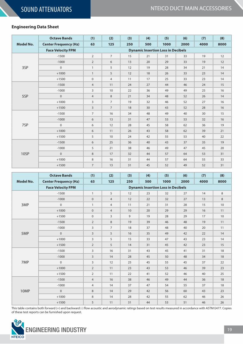
Engineering Data Sheet
Model No.
Octave Bands (1) (2) (3) (4) (5) (6) (7) (8)
Center Frequency (Hz) 63 125 250 500 1000 2000 4000 8000
Face Velocity FPM Dynamic Insertion Loss in Decibels
3HP
-1500 6 10 19 28 39 43 25 16
-1000 6 10 18 27 39 42 25 16
0 6 7 17 26 37 43 26 13
+1000 7 7 16 24 35 42 28 17
+1500 6 6 16 23 34 42 29 17
5HP
-1500 9 17 36 46 48 40 34 22
-1000 8 16 33 45 51 44 51 22
0 7 13 29 42 58 62 45 25
+1000 6 12 26 40 57 60 48 27
+1500 6 12 25 39 54 51 45 28
7HP
-1500 10 24 41 43 47 48 37 30
-1000 10 23 40 48 51 52 48 34
0 9 19 38 47 59 63 55 34
+1000 8 16 36 47 59 62 55 39
+1500 8 16 34 46 57 55 46 36
10HP
-1500 12 36 46 50 50 44 35 35
-1000 11 34 46 58 57 47 47 40
0 10 29 44 58 64 64 59 45
+1000 10 26 43 58 63 63 58 49
+1500 9 25 42 60 64 57 54 50
This table contains both forward (+) and backward (-) �ow acoustic and aerodynamic ratings based on test results measured in accordance with ASTM E477. Copies of these test reports can be furnished upon request.
ENGINEERING INDUSTRY 18
NTEICO DUCT MAIN ACCESSORIESSOUND ATTENUATORS
Engineering Data Sheet
Model No.
Octave Bands (1) (2) (3) (4) (5) (6) (7) (8)
Center Frequency (Hz) 63 125 250 500 1000 2000 4000 8000
Face Velocity FPM Dynamic Insertion Loss in Decibels
3SP
-1500 2 7 15 21 31 33 19 12
-1000 2 6 13 20 29 33 19 12
0 1 5 12 19 28 34 21 14
+1000 1 5 12 18 26 33 23 14
+1500 0 4 11 17 25 33 23 14
5SP
-1500 4 11 24 27 44 46 24 15
-1000 3 10 22 36 49 49 25 16
0 4 8 21 34 48 52 26 14
+1000 3 7 19 32 46 52 27 16
+1500 3 7 18 30 43 52 28 16
7SP
-1500 7 16 34 48 49 40 30 15
-1000 6 13 31 47 53 53 32 16
0 6 12 28 45 58 62 36 19
+1000 6 11 26 43 58 62 39 21
+1500 5 10 24 42 55 53 40 22
10SP
-1500 6 25 36 40 43 37 35 19
-1000 5 21 38 46 49 47 45 20
0 8 17 32 44 57 64 53 31
+1000 8 16 31 44 57 64 55 33
+1500 7 13 31 45 52 49 52 31
Model No.
Octave Bands (1) (2) (3) (4) (5) (6) (7) (8)
Center Frequency (Hz) 63 125 250 500 1000 2000 4000 8000
Face Velocity FPM Dynamic Insertion Loss in Decibels
3MP
-1500 1 5 12 23 32 27 14 8
-1000 0 4 12 22 32 27 13 8
0 1 4 11 21 31 28 15 10
+1000 0 4 10 20 29 29 16 11
+1500 0 3 9 19 28 29 17 10
5MP
-1500 2 8 19 39 46 48 19 11
-1000 3 7 18 37 48 40 20 11
0 3 5 16 35 49 42 22 14
+1000 3 5 15 33 47 43 23 14
+1500 2 5 14 31 45 42 23 15
7MP
-1500 3 16 31 43 45 41 31 18
-1000 3 14 28 45 50 48 34 18
0 3 12 25 45 55 45 37 22
+1000 2 11 23 43 53 46 39 23
+1500 2 11 22 41 52 46 40 25
10MP
-1500 4 16 38 46 49 44 36 18
-1000 4 14 37 47 54 55 37 18
0 8 14 29 42 56 60 43 23
+1000 8 14 28 42 55 62 46 26
+1500 5 11 31 44 53 51 46 26
This table contains both forward (+) and backward (-) �ow acoustic and aerodynamic ratings based on test results measured in accordance with ASTM E477. Copies of these test reports can be furnished upon request.
ENGINEERING INDUSTRY 19
DUCT MAIN ACCESSORIESACCESS DOORS, VOLUME DAMPERS
VAV, SOUND ATTENUATORS
NTEICO FACTORY:Industrial Area #12
Sharjah, United Arab EmiratesTel: +971 6 5438633 | Fax: +971 6 5438651
- - - - - - - - - - - - - - - - - - - - - - - - - - - - - - - - - -
NTEICO DUBAI OFFICE:Tower 51 @ Business Bay, P.O. Box: 236613,
Dubai, United Arab EmiratesTel: +971 4 348 0012 | Fax: +971 4 394 1994
[email protected] | www.nteico.com