
Belarus Tractor Operators Manual - Jensales · Belarus Tractor Operators Manual
Upload
siclano-silvaCategory
view
14download
1description

DualityOperator’s Manual
Solid State Logic
82S6DUA20C

Solid State LogicS O U N D | | V I S I O N
Begbroke, Oxford, England, OX5 1RU • +44 (0)1865 842300
320 West 46th Street, 2nd Floor, New York, NY 10036, USA • +1 (1) 212 315 1111Suite 401, 5757 Wilshire Blvd, Los Angeles, CA 90036, USA • +1 (1) 323 549 90903-55-14 Sendagaya, Shibuya-Ku, Tokyo 151-0051, Japan • +81 (0)3 5474 1144
7 bis, rue de la Victoire, le Blanc Mesnil, Paris 93150, France • +33 (0)1 48 67 84 85Via Timavo 34, 20124 Milano, Italy • +39 (0)39 2328 094
Visit SSL at URL: http://www.solidstatelogic.comVisit SSL at URL: http://www.solid-state-logic.com
© Solid State LogicAll rights reserved under International and Pan-American Copyright Conventions
Duality, SuperAnalogue, VHD, Total Recall, Solid State Logic and SSL are trademarks of Solid State LogicAll other product names and trademarks are the property of their respective owners
No part of this publication may be reproduced in any form orby any means whether mechanical or electronic without thewritten permission of Solid State Logic, Oxford, England
As research and development is a continual process, Solid State Logic reserves the rightto change the features and specifications described herein without notice or obligation
E&OE

11 IInnttrroodduuccttiioonn ttoo DDuuaalliittyy
22 CCoonnssoollee OOppeerraattoorr’’ss GGuuiiddee
Overview 2-1DAW I/O Labelling 2-2Routing and Signal Flow 2-2Introduction to Split Mode 2-2Channel Strip 2-3
Channel Input Section 2-4Dynamics Section 2-5
Compressor 2-5Gate/Expander 2-5Central Dynamics Control 2-7Dynamics Section Metering 2-7
Equaliser 2-7Filters 2-7Channel Output (CHOP) 2-8Insert Point 2-8Signal Processor Routing 2-8Channel Sends 2-9Cue Stereo 2-9FX Sends 2-9Channel Pan 2-10Split Mode 2-10Channel Fader 2-11Channel Cut and Solo 2-11D-pot and DAW Control 2-11Channel TFT Screen 2-12
Centre Section 2-15Power Supply Indicators 2-15Central Routing Panel 2-16Main Output Functions 2-18Main Bus Compressor 2-19Master Fader 2-20Track Bus Master Controls 2-21Monitoring 2-22
External Source Selectors 2-23Monitor Insert 2-24Monitor Metering 2-24Bass Management 2-25Monitor Options 2-25Monitor Level Calibration 2-27SOLO / AFL / PFL 2-28
Duality Operator’s Manual TTOOCC--11
Table of Contents
TTaabbllee OOff CCoonntteennttss

22 CCoonnssoollee OOppeerraattoorr’’ss GGuuiiddee ((ccoonnttiinnuueedd))Cue/FX Send Master Controls 2-29Foldback and Headphone Outputs 2-29Stereo Return Channels 2-30Misc Options 2-31Communications 2-32Oscillator 2-33LFE Channel 2-34Mix Reassign Matrix 2-34Stereo Mix Matrix 2-34Group Control Faders 2-35Section Metering 2-36Meter Options 2-37
33 DDAAWW CCoonnttrrooll GGuuiiddeeIntroduction 3-1
DAW Controller features summary 3-1Communication with the DAW 3-1Overview 3-2
D-pots 3-2Console Focus Button 3-2
Master Control Panel 3-3Channel Banking Controls 3-3DAW Window Buttons 3-3Digital ‘In-line’ Mode 3-3DAW Utility Buttons 3-4Modifier Buttons 3-4Default Button 3-5
Channel Functions 3-6DAW Meters 3-6Channel Fader 3-6
Channel Solo and Cut Panel 3-7Channel D-pot 3-7Solo and Cut Buttons 3-7Solo Isolate 3-7Channel Select Button 3-7Scribble Strip Displays 3-7
Record Ready Mode 3-8Edit Mode 3-8Select Mode 3-9
Working with the Channel D-pots 3-9Pan Mode 3-9Channel Mode 3-9Send Mode 3-9
Setting Sends Pre/Post Fader 3-10Muting a Send Output 3-10Flipping Send Levels to the Faders 3-10
Table of Contents
TTOOCC--22 Duality Operator’s Manual

33 DDAAWW CCoonnttrrooll GGuuiiddee ((ccoonnttiinnuueedd))Input, Output and Send Routing 3-11
Viewing Routing 3-11Changing Routing 3-11
Motion Control 3-12Basic Transport Controls 3-12Additional Transport Controls 3-12Other useful transport modes 3-13
Setting start (In) and end (Out) Times 3-13Setting Pre and Post Roll 3-13Audition 3-13Footswitch Control 3-14Zoom, Navigation and Selection Modes 3-14Shuttle/Scrub Wheel 3-15Numeric Keypad 3-16
Plug-In Editor 3-17Plug-In Editor Display 3-17Plug-In Editor Controls 3-17Paging Buttons 3-17Selecting a DAW Channel for Plug-In Control 3-18Timecode/Bars & Beats/Samples Display 3-18Plug-In Display Modes 3-18Viewing Current Inserts (Insert Mode) 3-18Assigning a Plug-In or Hardware I/O Insert 3-19Editing Plug-In Parameters (Parameter Mode) 3-19
Soft Keys 3-21Working with DAW Automation 3-24
Automation Enable 3-24Automation Modes 3-24
TRIM Mode 3-24Automation Status Display 3-25Suspending Automation 3-25Writing Automation 3-25Automating Cuts 3-26Automating Pans and Sends 3-26Automating Plug-Ins 3-26
Mackie Control (MCU) Emulation 3-27Mackie Function Control Overview 3-28Logic Template 3-29Nuendo/Cubase Template 3-32Sonar Template 3-35Digital Performer Template 3-38
Duality Operator’s Manual TTOOCC--33
Table of Contents

44 TToottaall RReeccaallllOverview 4-1Total Recall and Projects 4-2
Working with Projects and Titles 4-3Saving a TR Setup 4-3Recalling a TR Setup 4-4Deleting a TR Setup 4-4Renaming TR Setups 4-4Total Recall Displays 4-5Copying and Swapping settings between channels 4-6Resetting soft switches 4-6Copying TR Setups to a DAW Folder 4-6
55 AAuuttoommaattiioonnOverview 5-1Key Features 5-1Automation and Projects 5-2Working with Projects and Titles 5-3Activating the Automation System 5-3Operation 5-4
List Mix Menu 5-4Changing the Selected Mix Pass 5-4Deleting Mix Passes 5-4
Creating A New Mix Pass 5-5Mix Running 5-6Mix Review 5-6Dedicated Automation Buttons 5-7Join and Revise 5-8Discard 5-9Updating a Mix Pass 5-9
Protection Modes 5-9Automation Options 5-10
Trim 5-10Trim Lock 5-11Motors Off 5-12Snap Mode 5-12AutoTakeover 5-12Cut Automation 5-13
Using Match and Play to correct a Cut 5-13Copy and Swap 5-14Fader Links 5-15
Creating a New Link 5-15SuspdSel/SuspdAll 5-15Deleting Links 5-15
Saving Mix Passes to your DAW Project 5-16Pro Tools Setup Notes 5-17
Table of Contents
TTOOCC--44 Duality Operator’s Manual

66 LLooggiiccttiivviittyy –– DDuuaalliittyy RReemmoottee BBrroowwsseerrIntroduction 6-1Duality Remote 6-1Connecting Duality To Your Computer 6-2
Setting a Fixed IP Address 6-2Connecting to Duality 6-3
Project Tab 6-4Copying Titles, Total Recall and Mix Data Between Projects 6-4Renaming Projects, Titles, Mixes or Total Recall Setups 6-5
Backing up a Project 6-5Restoring a Project 6-5
Notes Tab 6-5Channel Tabs 6-6
Mixes 6-7Total Recall 6-8Exts Names 6-9Misc Tab 6-10
Time and Date 6-10
Duality Operator’s Manual TTOOCC--55
Table of Contents

Table of Contents
TTOOCC--66 Duality Operator’s Manual

What is Duality?Duality is an evolutionary combination of super analogue console and DAW controller from Solid State Logic. Itdraws on years of design experience, and incorporates industry standard features from SSL’s range of largeformat music consoles.
Design ConceptsDuality combines technology from SSL’s acclaimed music console, the XL 9000 K Series with new designconcepts which faithfully recreate the overload characteristics of valve circuitry. It retains all of the sonicbenefits of SuperAnalogue™ capacitor-free servo coupled circuitry, then adds variable harmonic colouration ona channel by channel basis, contained within a control surface which will be familiar to any recording engineerwho has previously used SSL consoles.
Key Features Summary
• Combined large format SSL console and DAW controller
• Legendary SuperAnalogue™ mic preamps and signal processing
• New VHD™ (Variable Harmonic Drive) preamp stage
• Comprehensive monitoring up to 5.1 surround with multiple loudspeaker support
• Direct control of DAW recording, editing and mixing functions from the console surface
• Flexible signal routing enhanced by the channel ‘Split’ function
Console Feature Summary
• Integrated console, signal acquisition, signal processing, studio monitoring, bass management and DAWcontrol
• Advanced DAW control through a high resolution integrated TFT screen
• Elegant, ergonomic design with a number of add on options
• Innovative large fader dual-control of both DAW and console input path with follow fader metering
Duality Operator’s Manual 1-1
Introduction
Section 1 – Introduction

Exceptional Signal Processing• Legendary SSL sound quality
• SuperAnalogue™ technology derived from SSL’s acclaimed XL 9000 K Series console
• VHD™ Input Preamp
• DC Coupled for excellent low frequency response
• Balanced signal paths throughout for maximum dynamic range
• Audio bandwidth exceeding that of 192kHz recorders
• Ultra low-noise dual impedance mic amps
• Channel EQ with twin-curve SSL E and G Series 4-band parametric equalisation
• Channel dynamics sections with gate, expander and compressor/limiter
• 5.1 implementation of SSL’s classic mix bus compressor
• Highly flexible signal processing order
Creative Versatility• Hex mix bus design configurable as a 5.1 bus or three stereo pairs (A, B, C)
• 5.1, stereo or stereo down-mix main outputs
• 24 track busses
• 2 Stereo Cue plus four Aux busses on all channel modules, with EFX re-assign system to feed track bussesand channel output
• Wide range of solo modes including Solo-In-Front
• 4 stereo echo returns with full mix/foldback routing
• Unrivalled studio monitoring section
• Hi-visibility channel TFT screens for metering and optional Total Recall displays
• 2 main VU meters and phase meter
• Comprehensive bus metering in the centre section
Introduction
1-2 Duality Operator’s Manual

DAW ControllerToday’s DAWs provide the power and convenience of recording and editing audio, but a keyboard and mouseis not the most intuitive way to access these controls. For most users, finding an integrated solution thatanswers all of their working needs is strongly desired. Duality achieves this to an extent and quality that haspreviously been unavailable.
Controller Features Summary• Direct access to all major DAW mixing, editing and automation parameters via HUI and MCU protocols
• Direct control of plug-in settings
• Dedicated control processor to maximise console performance
• Integral colour TFT display with dedicated control keys
• High quality motorised faders to write/replay level moves in your DAW
• Simple switching between console layer and DAW control layer
• Full remote control implementation
• Operation independent of platform – works with Pro Tools™, Nuendo™, Logic Audio™, and others
System Options• Multi-operator Total Recall for accurate resetting of session parameters• Comprehensive automation package based on SSL’s legendary Ultimation system
Now enjoy.......
Duality Operator’s Manual 1-3
Introduction

About this manualThis manual is divided into five main sections, and is designed to provide a comprehensive source ofinformation for Duality console users. The table of contents will help you to familiarise yourself with the basiccontent of each section. If you are reading this from an electronic version of the manual, use the ‘bookmark’feature to rapidly locate to virtually any topic.
If you have not previously used an SSL console, you are advised to read the Duality overview at the start ofSection 2. Those of you who have experience of SSL’s range of analogue consoles will have little difficultygetting to grips with the operation of this console’s control surface; features that are specific to Duality are fullydescribed in Section 2.
To set-up and configure the software interface between Duality and your chosen DAW, please study Section 3.This section also covers the DAW functions that you can usefully control from Duality’s centre section.
Finally, the last section in this manual is provided to hold useful appendices that you may be supplied with fromtime to time.
Conventions Used
Some typographical conventions have been used in this manual to help distinguish explanatory text from thetext referring to console items. They are as follows:
• Switch cap engravings on the console are usually in UPPERCASE (eg. SOLO).
• Silk screened text on the console’s control surface can be either UPPERCASE (eg. DYNAMICS), or
lowercase bold (eg. auto), or Titlecase (eg. Talkback Mix).
• Any text on the console’s TFT screen is referred to in a Bold typeface.
• Items of note or cautions are shown in a red italic typeface.
• Whenever this manual mentions the selection or pressing of a button, it is assumed that the button was not
active (ie. not lit), and that this action has made it active (ie. it has become lit).
• Similarly, whenever the manual mentions the deselection of a button (or pressing it again), it is assumed that
it was active before the action, and has become inactive due to this action.
Contacting Solid State LogicIf you cannot find the information you need on the pages of this manual, please refer to the Duality support
pages at http://www.solid-state-logic.com
About This Manual
1-4 Duality Operator’s Manual

Duality Operator’s Manual
Overview
Duality is an evolutionary combination of analogue console and DAW controller from Solid State Logic. It drawson years of design experience, and incorporates industry standard features from SSL’s range of large formatmusic consoles.
Duality combines technology from SSL’s acclaimed music console, the XL 9000 K Series with new designconcepts which faithfully recreate the overload characteristics of valve circuitry. It retains all of the sonic benefitsof SuperAnalogue™ capacitorless servo coupled circuitry, then adds variable harmonic colouration on a channelby channel basis, contained within a control surface which will be familiar to any recording engineer who haspreviously used SSL consoles.
The ubiquitous DAW (Digital Audio Workstation) has brought many benefits to audio production, including visualaudio editing, integrated digital effects processing and convenient session storage and recall. However, althougheminently flexible, DAW’s present new challenges of integration within the studio environment today.
Duality has been carefully designed with these requirements in mind. It addresses all the needs of current DAWproduction techniques in an integrated, high quality and robust design, coupled with all of the sonic benefitsexpected from a Solid State Logic console.
SSL’s extensive design experience has been utilised to create the ultimate capture path for up to 96simultaneous inputs into the DAW, where recorded signals can be edited, processed and mixed via Duality’scontrol surface. The signal paths can then be either summed internally within the DAW or returned to theanalogue domain for further processing via Duality’s channel path EQ and dynamics processors, before finalsumming via the console’s balanced analogue mix bus architecture. With a comprehensive 5.1 monitoringsection, audio can be auditioned with the highest possible audio integrity.
A high resolution, digitally controlled gain element in each channel allows the motorised faders to be switched tocontrol any DAW that supports the HUI or Mackie Control protocols, while retaining control of the analoguesignal path. The faders and their associated channel-based rotary encoders (D-pots) provide direct control ofDAW faders, pans, sends, plus input and output routing. The Master Control Panel and Duality’s centre sectionscreen give paged control of all plug-in parameters.
In summary, Duality is a Complete Studio Solution for modern DAW based production environments.
2-1
Section 2 – Console Operator’s Guide

An Introduction to Split Mode
The Duality channel strip is optimised for working in conjunction with a multichannel DAW as the primaryrecording medium. Instead of retaining the ‘in-line’ architecture of previous SSL consoles, a new ‘Split Mode’mode topology has been introduced which provides the equivalent of in-line operation but without the cost andcomplexity of separate channel and monitor paths.
In DAW-based productions, there is no longer the fixed track count limitation of conventional analogue or digitaltape-based recording. This means that most sources are recorded individually to a track with or withoutprocessing as production requirements dictate, but without requiring constant access to a ‘channel’ fader. TheDuality channel supports two input paths normally designated as the Channel Input and the DAW Return, witha single Channel Output as the DAW Send. The Split Mode architecture allows the input signal to be ‘pickedoff’ the channel path at the input stage, or pre fader, and replaced with the DAW return. The input signalautomatically becomes the DAW send and the remaining section of the channel handles the DAW return.Toggling Split Mode on and off is the equivalent of the classic send/return (Group /Tape) monitoring. Theconsole sends can select either the channel fader signal or the channel output signal as a source, offering thechoice of zero-latency stereo cue and FX mixes, or post-DAW processed sends.
Routing and Signal Flow
As you read through the following pages, you may find it useful to refer to the signal flow diagrams in theappendices section at the end of this manual.
In order to understand signal flow through Duality’s various operational modes, first we need to discuss howyour DAW I/O unit is connected to the console. To take advantage of the sonic and control environmentprovided by Duality, it is recommended that each DAW output is returned individually to a Duality channel strip.
For details of the physical location of Duality’s inputs and outputs, please refer to the Duality InstallationManual.
DAW I/O LabellingWhen using DAW routing with Duality, it is advisable to take time to sensibly label the inputs, outputs andbusses within your DAW. Details on how to do this will be found in the documentation supplied with the DAW.Sensible labelling will make the task of performing routing via Duality’s front panel a simple task, rather thanrelying on having to decipher long complex names often assigned by default to DAW channels.
For example in a 48 I/O system, simply naming inputs and outputs ‘1’ through ‘48’, and busses ‘b1’ through‘b48’ will allow a simple differentiation between hardware I/O and internal DAW busses when using the consolecontrol surface. In some DAW systems, I/O paths can be grouped. In this case label stereo paths in pairs suchas ‘1-2’, and sub paths as ‘1’ and ‘2’.
Console Operator’s Guide
2-2 Duality Operator’s Manual

Channel Strip
IntroductionDuality’s Split Mode enables the channel processing to be easily applied to channel inputsignals feeding the DAW record path or to the DAW returns. This provides the equivalent of in-line operation but without the complexity of separate channel and monitor paths.
Users who are familiar with SSL’s range of in-line consoles will soon realise that the channelstrip faders can control virtual faders on the workstation as well as the channel signal path , inmany ways paralleling the large/small fader configuration of an in-line channel strip. Thisprovides an alternative to Split Mode working, with the DAW console handling the functions ofa monitor mixer.
The channel supports two input connections, the Monitor Input which is normally sourcedfrom the output of the DAW, and the Channel input which accepts variable level signals froma microphone, DI box or other audio source. Three preamps are available for use with eitherinput: a unity gain line level buffer which is normally assigned to the DAW return, and a pair ofmic preamps sourced from the CHANNEL input XLR connector, one using SSL’s SuperAnalogue direct coupled DC servo circuitry, and the other featuring SSL’s proprietary VHD™(Variable Harmonic Drive) valve emulation gain stage. The channel output can route to 24Track Busses, any one of three stereo Main Mix Busses (A, B and C) or all the Main MixBusses in 5.1 mode.
In addition to two Cue Stereo sends and four mono FX Sends, a dedicated Direct Output (CHOP) is provided. Each channel has comprehensive routing for EQ and filter, dynamics, andinsert send/return points.
The channel strip can be divided into five distinct functional sections:
Channel input
Dynamics
EQ and filter
Cue Stereo and FX outputs
Channel output pan
Beneath the channel strips is a panel containing the ‘D-pot’ for DAW output or channel levelcontrol. This area also houses cut and solo buttons for both fader and D-pot, and an electronicscribble strip. Finally, below the ‘write-your-own’ scribble strip, each channel has a long-throw(100mm) moving fader.
Above each bay of six channel strips, the TFT meter display provides a large range of usefulinformation on a per-channel basis, including audio and dynamics metering, processing order,bus routing, automation bargraphs (optional) and Total Recall™ (optional).
5
4
3
2
1
F R
LR LCR
L R
LFE
Focus
5.1
SPLIT
PAN TO TRK
LMF
dB
Q
KHz
Hz
Q
+
.2 2.0
40 600
KHz
HMF
dB +
0
KHz.6 7
LF
THRESHOLD+10
0
BELL
BELL
dB
0
LF
+
0
HF
dB +
0
Hz50020
CUE ST
L R
FX1
FX2
EQIN
POST
INSIN
CH OP
FX4
HF
OUT 3
KEY
G-EQ
RATIO1 20
SRCSELAFL
EFX
ON
ALT
CH OP
POST
SET EFX/CUEB
SRCSEL
CH OP
CH OP
FX3
TOS/Ch
RELEASE1 41 4
THRESHOLD
RANGE0 40
GATE/EXP
.1 4
+10- 30
0
DYNIN
REL/HOLD
PK
Cue B
EFX
ON
EFX
ON
CH OP
CH OP
EFX
ON
EFX
ON
EXP
POSTEQ
COMPRESSOR
INPUT
CH
dB-20 +20
48V
dB+15 +75
PAD
2nd 3rd
FILTto
INP
Ø
HI-Z
60
150
220
400
.3
.6
1.0
DRVIN
kHZ
-
-
-
1
2 3
5
30
9 6
4
30
60 100
300
S/ChLSTN
FILTERS
HOLD
Push for Fst Att
LINK
0
Push for Fst Att
DRIVE
- 20
1.5 22
15
105
2
1
2
3
4
5
Channel Strip
2-3Duality Operator’s Manual

At your first introduction to the Duality console, you will immediately see that the channel strip controls arepresented in reassuringly familiar manner. The following pages describe each control in detail, with briefcoverage of the routing possibilities. See the start of this section for more on signal routing.
In the following descriptions, the connectors referred to are on the rear of each channel module,unless stated otherwise.
Channel Input SectionThis provides two inputs, one dedicated as a line level DAW return (D-connector), theother (XLR connector), is intended as a mic input but may be used for both mic or lineinputs. Normally the Mic Input feeds the variable gain INPUT amplifier, and the DAWreturn feeds a unity gain line amp. However a centrally controlled INPUT FLIP functionreverses the input routing so that the DAW return can be processed by the variable gainamplifier stage without the necessity for external patching.
The variable gain amplifier features two completely independent preamp stages. Both have electronicallybalanced inputs with very different but complementary sonic qualities. The default preamp uses SSL'sacclaimed Super Analogue circuitry to provide an extremely low noise, extended bandwidth front end with theminimum of signal colouration. Pressing the DRV IN button routes the input signal to a completely differentpreamp featuring the SSL-developed VHD™ (Variable Harmonic Drive) circuitry. VHD emulates thecharacteristics of a classic valve front end but with the option to tailor the harmonic mix when the preamp isoverdriven by adjusting the DRIVE pot. In conjunction with the 20dB PAD and Hi-Z input impedance option,VHD can provide subtle valve style warmth to a mic signal or aggressive tonal shaping to existing DAW tracks.However, be aware that, due to differences in the mic amp topology, exact matching of gains is not possible.
Note that many of the signal routing functions on a channel strip are also availableon the central routing panel, and some are only available on the central routing panel
The post input stage CH (channel) control provides final ±20dB gain trim (for reducing the level when the inputsection is being abused for creative reasons) and polarity inversion (Ø), for the centrally selected channelsource. Available input options are the output of the mic input preamp (MIC), the balanced line level DAWreturn (LINE), or the channel’s associated track bus for patch free subgroups (BUS). In the latter case, thechannel input is replaced by the output of one of the 24 Track Mix busses where Bus N feeds the input ofChannel N, N+24, N+48 etc.
FILT to INP locks the high and low pass filters to the channel source. +48V phantom power for mic inputs isselected on the central routing panel.
COMPRESSOR
INPUT
CH
dB-20 +20
48V
dB+15 +75
PAD
2nd 3rd
FILTto
INP
Ø
HI-Z
DRVIN
0
DRIVE
Console Operator’s Guide
2-4 Duality Operator’s Manual

Dynamics SectionThe Dynamics section contains a compressor section identical to that of the 9000Kseries and also found in SSL's Logic FX range of outboard processing units. In normaluse, the compressor’s true r.m.s. side chain and over-easy soft ratio function provide avery transparent compression action even with large amounts of gain reduction. The fastattack option offers the classic SSL compressor sound normally associated with its useon drum and percussion sources. Selecting Peak (PK) mode defeats the over-easy softratio, modifies the release curve and attack times, and unleashes a far more aggressivesounding compressor ideal for more radical sonic shaping.
The Gate/Expander section is a new variant of SSL’s classic 4000 series three-controldesign. It features the choice of a steep gate or gentle expander slope, with optional fastattack. The new ‘Hold’ (HOLD) option flips the variable release (REL) control to function asa variable hold-off time with a fixed release curve.
The complete section is switched in or out of circuit using the DYN IN button (see also Central RoutingControl). When the dynamics section is in circuit, the DYN box on the channel TFT display is highlighted.
Individual controls act as follows:
Compressor
RATIO – When turned to 1:1, the compressor section is inactive. Turning the control clockwise increases thecompression ratio until it reaches a true limit mode at the fully clockwise position. Pressing the RATIO knobswitches the compressor to peak sensing, and replaces the ’over easy’ characteristic with a hard knee,providing an alternative voicing for some instruments. The PK LED lights to indicate that this option has beenselected.
THRESHOLD – Whenever a signal exceeds the level set by this control, the compressor will start to act at theratio set by the RATIO control. This control, in conjunction with the Ratio setting, provides automatic make-upgain, so as you lower the threshold and introduce more compression, the output level is increased, maintaininga consistent output level.
RELEASE – Sets the time constant (speed) with which the compressor returns to normal gain settings oncethe signal has fallen below the compressor threshold. This control also incorporates a push-push switch whichselects a very fast attack time as an alternative to the standard time constant.
Gate/ExpanderThis section can act as a Gate or as a 2:1 Expander when the RANGE pot is pressed. A red LED indicates thatExpand mode has been selected.
RANGE – Determines the depth of gating or expansion. When turned fully anticlockwise (Range = 0), thesection is inactive. When turned fully clockwise, an attenuation range of 40dB can be obtained.
THRESHOLD+10
0
HF
KEY
RATIO1 20
RELEASE1 41 4
THRESHOLD
RANGE0 40
GATE/EXP
.1 4
+10- 30
0
DYNIN
REL/HOLD
PK
EXP
POSTEQ
COMPRESSOR
dB-20 +20
9 6
S/ChLSTN
HOLD
Push for Fst Att
LINK
Push for Fst Att
- 20
Dynamics Section
2-5Duality Operator’s Manual

THRESHOLD – Variable hysteresis is incorporated in the Threshold circuitry. For any given ‘open’ setting, theExpander/Gate will have a lower ‘close’ threshold to prevent ‘hunting’ artifacts. The hysteresis value isautomatically increased as the Threshold is lowered. This is very useful in music recording as it allowsinstruments to decay below the open threshold before gating or expansion takes place.
REL/HOLD – This determines the time constant (speed), variable from 0.1- 4 seconds, at which theGate/Expander reduces the signal level once it has passed below the threshold. Note that this control interactswith the Range control. This control also incorporates a switch which, when pushed, provides a fast attack time(100µs per 40db), instead of the normal linear attack time of 1.5ms per 40dB. The attack time is the time takenfor the Expander/Gate to ‘recover’ once the signal level is above the threshold. When gating signals with asteep rising edge, such as drums, a slow attack may effectively mask the initial THWACK, so you should beaware of this when selecting the appropriate attack time.
HOLD – When this button is pressed, the release time is fixed at 150ms but the hold time can be variedbetween 0 and 4 seconds by adjusting the REL/HOLD pot.
The LINK button in the compressor section links the sidechain signal of that unit to the sidechain of the nextdynamics section to the right. When two dynamics sections are linked, the control voltages of each section sumtogether, so that whichever section has the most gain reduction will control the other section.
Don’t try to link two gates using the LINK button when you want the signal on one to open the other. If youneed to achieve this effect, take a keying signal from one section to trigger the other. The easiest way to do thisis by patching from the insert send of the ‘source’ channel into the Key input (see below) of the ‘destination’channel, and selecting the KEY button on this channel.
The KEY button feeds whatever signal is present on a channel’s Key input (D-connector) into the sidechaininput of that channel’s dynamics section. Pressing S/Ch LSTN routes the sidechain signal to the console’s PFLbus. This simplifies the set up when either an external key input or the filters to side chain option is in use.
POST EQ (not surprisingly) places the dynamics section post the EQ section (see also Central DynamicsControl below.
Note that when the dynamics section is not in circuit, its sidechain input is also bypassed.
Signal processing order is graphically displayed on the channel TFT screen
Console Operator’s Guide
2-6 Duality Operator’s Manual

Central Dynamics ControlThe centre section master routing panel replicates the dynamics POST EQ function for sweet spot control andmultiple channel operation using the SELECT/TO range keys.
Dynamics Section MeteringThe TFT screen above each bay of six channel strips is used to display a wide variety of relevant information.In its default Channel mode, as well as channel output metering (see later) a display of dynamics section gainprocessing is shown, in the form of two columns of indicators – yellow and red for the compressor, green forthe gate/expander. See Channel Metering for more information.
FiltersThese comprise a 3rd Order 18dB/Octave high pass filter (HF) and a 2nd Order12dB/Octave low pass filter (LF). Each filter is out of circuit when the control is fullyanticlockwise. When the filter is in circuit, the FILTER box on the channel TFT display ishighlighted.
Normally, the filters follow the EQ section in the signal chain but the FILT to INP buttonin the input section of the channel strip places the filters directly after the channel input.This function is also available on the central routing panel. Pressing TO S/ch routes thefilter section to the dynamics sidechain.
Signal processing order is graphically displayed on the channel TFT screen
EqualiserThis is a four band parametric equaliser based on SSL’s classic 'Black Knob' EQ, whichwas developed for the original SL4000E series console. Selecting the G-EQ buttonintroduces steeper shelving curves with a controlled amount of undershoot at theturnover frequency, together with the classic gain/bandwidth interaction for the mid bandsections that was a key characteristic of the original G-Series EQ.
The individual bands function as follows: HF high frequency shelving equaliserswitchable to fixed Q parametric (BELL); HMF high frequency parametric mid bandequaliser; LMF low frequency parametric mid band equaliser; LF low frequency shelvingequaliser switchable to fixed Q parametric (BELL). The EQ IN button (located next to theinsert buttons) routes the channel signal through the EQ and filter section. When incircuit, the EQ box on the channel TFT display is highlighted. See also Central RoutingControl.
LMF
dB
Q
KHz
Hz
Q
+
.2 2.0
40 600
KHz
HMF
dB +
0
KHz.6 7
LF
BELL
BELL
dB
0
LF
+
0
HF
dB +
0
Hz50020
EQIN
POST
INSIN
HF
OUT 3
G-EQ
TOS/Ch
IN
60
150
220
400
.3
.6
1.0
kHZ
-
-
-
1
2 3
5
30
9 6
4
30
60 100
300
FILTERS
1.5 22
15
105
2
Filters and EQ
2-7Duality Operator’s Manual

Insert The INS IN button routes the channel signal via balanced insert send and return points,available on the rear of the console (D-connectors). The insert defaults to the channelinput (post the input trim); POST cycles the insert position through two alternativelocations in the processing path: post EQ or post Dynamics; the centre section masterrouting panel provides individual INS POST EQ and INS POST DYN buttons. When theinsert is active, the INSERT box on the channel TFT is highlighted.
Signal processing order is graphically displayed on the channel TFT screen
Channel Output (CHOP)The Channel Output (D-connector) is normally used to feed the DAW input. The defaultsignal is a post channel fader feed, but the SRC SEL button can be used to selectalternative sources: pre channel fader (pre the SPLIT point – see below), the channelinput (also pre the SPLIT point), or an active EFX send (see below). Each selection isgraphically displayed on the channel TFT screen (see Channel Metering for moreinformation). When either the channel input or pre fader source is selected, the SPLITbutton activates the Split Monitoring function and routes the DAW return into the channelsignal path post the split point (see below).
Use the associated AFL button to monitor the channel output source as you togglethrough the options with the SRC SEL button. The central routing panel has single buttonselection of the four channel output sources: INPUT, PRE FADE, POST FADE, EFX.
Signal Processor RoutingBy now you will have realised that Duality features extremely flexible signal processor routing within eachchannel. In addition, the channel output (CHOP) can be sourced from a number of different points in thechannel. Furthermore, the SPLIT function effectively offers two signal paths in one channel strip. A usefulgraphic display on the channel bay TFT (see Channel Metering) makes clear, at any time, the currentarrangement for any channel.
LMF
dB
Q
KHz
Hz
Q
+
.2 2.0
40 600
KHz.6 7
BELL
dB
0
LF
+
0
CUE ST
L R
FX1
FX2
EQIN
POST
INSIN
CH OP
FX4
SRCSELAFL
EFX
ON
ALT
CH OP
POST
SET EFX/CUEB
SRCSEL
CH OP
CH OP
FX3
Cue B
EFX
ON
EFX
ON
CH OP
CH OP
EFX
ON
EFX
ON
60
150
220
400
.3
.6
1.0
-
-
Console Operator’s Guide
2-8 Duality Operator’s Manual

Channel SendsEach channel has two stereo and four mono sends that can be used for a number ofdifferent purposes: headphone feeds, FX sends, etc. The stereo cues can even be usedto provide an additional line input to the mix.
Cue StereoNormally, the stereo cue sources a pre channel fader signal, which routes to the console’sCue A bus. This in turn can be picked up in the centre section and used as a foldbacksource (see Cue/FX Master Controls). Press and hold down the SRC SEL button (at thebase of the Channel Sends section) then press the stereo cue gain pot to toggle the sourcethrough post fader channel feed (POST), channel direct output (CHOP) or the alternativechannel input (ALT), as indicated by the LEDs adjacent to the stereo cue gain pot. The ALTselection is defined as whichever input is not assigned to the main channel path (whenSPLIT mode is not active), and allows the stereo cue to be used as an additional input.
Likewise, select the stereo cue output to Cue B by holding down the SET EFX/ CUE Bbutton then pressing the stereo cue gain pot; this toggles the selection through Cue B, EFXand Cue A (off).
Master controls for the Cue A and B busses can be found in the centre section.
Pan your mono source across the stereo cue bus outputs with the LR pan control. Thestereo cue send is turned on/off by means of a push-push switch mounted on the send levelcontrol.
FXSendsThe four mono FX Sends are normally sourced post channel fader. They may, however, be sourced from thechannel output (CHOP) by pressing and holding down the SRC SEL button (at the base of the Channel Sendssection) then pressing the required FX gain pot to toggle the selection on/off.
Each FX level pot is fitted with a push-push on/off switch; ‘on’ is indicated by a LED beside the pot. Master controlsfor each FX bus can be found in the centre section.
Selecting an FX output to the EFX system (press and hold the SET EFX/ CUE B button then press the required FXor Cue Stereo gain pot) allows a single send to be isolated from its associated bus and to be used as source foreither the Track Busses (selected in the centre section), or the channel output — CHOP (selected locally or in thecentre section). This enables additional independent effects send or headphone mixes to be easily generated.Logic interlocks prevent feedback paths by disallowing the EFX function on a send sourced from the channel outputif EFX to channel output is active.
See Cue/FX Master Controls for more on EFX routing.
LMF
dB
Q
KHz
Hz
Q
+
.2 2.0
40 600
KHz.6 7
BELL
dB
0
LF
+
0
CUE ST
L R
FX1
FX2
EQIN
POST
INSIN
CH OP
FX4
SRCSELAFL
EFX
ON
ALT
CH OP
POST
SET EFX/CUEB
SRCSEL
CH OP
CH OP
FX3
Cue B
EFX
ON
EFX
ON
CH OP
CH OP
EFX
ON
EFX
ON
60
150
220
400
.3
.6
1.0
-
-
Channel Sends
2-9Duality Operator’s Manual

Split ModeWhen the channel output (DAW input) is sourced from either the channel input or pre thechannel fader, SPLIT offers a new approach to in-line tracking on an analogue console byreturning the DAW output back into the channel path just after the channel output pick offpoint. By using INPUT or PRE FADE as the channel output source, clean or processedsignals are routed to the DAW input, with the option to use the remaining channel processingand routing to monitor the DAW return in the analogue domain.
The effect of SPLIT is graphically illustrated on the channel TFT (see Channel Metering for more information).
Note that SPLIT is disabled if CHOP is sourced from POST FADE or EFX,or if the Line Amp is selected as the channel input.
Channel PanAt the bottom of the channel strip is a fully featured 5.1 panning section for both the Main Mix busses as wellas the 24 Track Busses. With the most complete implementation found on any analogue console, the featureset includes a dedicated LFE send and a fully variable ‘Focus’ control to alter the phantom/hard centre mix forsignals located in the front channels.
The default arrangement is for stereo panning to three pairs of Main Mix busses – A, B and C. The 24 TrackBusses normally pick up the mono post fader channel output. On the centre section routing panel, selectingPAN TO TRK routes the LR pan outputs to odd/even pairs of Track Busses. Selecting 5.1 PAN enables the full6-channel panning options for both the Main Mix busses and the Track Busses, if PAN TO TRK is alsoselected. Local LEDs in each panning section indicate whether that channel has been selected to either ofthese two modes. When 5.1 panning is not enabled, only the LR (Left/Right) pan control is active.
If the centre section function EFX TO TRK is selected, this replaces the normal feed to the Track Busses anddefeats 5.1 panning to the busses.
The channel panning section features XY style 5.1 panning via LR (Left/Right) and FR (Front/Rear) controlswith additional LFE and Focus functions. The LFE control feeds a variable amount of the channel output to adedicated LFE (subwoofer) bus (see more on this in the Centre Section).
The Focus control alters the proportion of input signal fed to the front Left/Right busses and the Centre bus,enabling channel signals to be focussed from a ‘hard’ centre, all the way through to a true phantom centre. Asthe Focus knob is rotated clockwise from the LR position, a centrally panned signal is progressively attenuatedin the left and right busses, while the gain to the centre channel is increased. When fully clockwise, the LR panpot becomes a three-channel discrete LCR panner. As the Focus control is returned to the LR position,variable amounts of divergence are introduced so that, at the 12 o’clock position, signal is present in the threefront channels at equal level. As you continue to turn before 12 o’clock, the centre channel is thenprogressively reduced, leaving only the phantom (Left + Right) centre image at the fully anticlockwise position.
F R
LR LCR
L R
LFE
Focus
5.1
SPLIT
PAN TO TRK
Console Operator’s Guide
2-10 Duality Operator’s Manual

D-pot and DAWControlBelow the channel strips is a 12-wide panel containing a rotary encoder known as theD-pot, together with its integral momentary switch mounted on the encoder shaft. This isused to adjust the currently assigned DAW parameter or the analogue channel level;D-pot functions are assigned from the centre section, and indicated in the D-pot’sassociated two line display.
The CUT and SOLO buttons above the encoder are used when the encoder iscontrolling the DAW or Duality channel gain.
The electronic scribble strip displays the channel name, the name of a DAW track,selected DAW send, or I/O data according to the function currently assigned on theMaster Control Panel (see Section 3). When the rotary control and the fader swap rolesfor gain control, entries in the scribble strip also flip.
The SEL button operates the DAW ‘Selected Channel’ function. This function can be re-assigned from the centre section, to track arm a selected DAW channel or assign the‘plug-in’ editor (Pro Tools only). Tallies in the channel meter display Record Ready andEdit status regardless of whether the console is in ‘DAW Focus Mode’ (see Section 3 formore details).
Channel Cut and SoloThe CUT and SOLO buttons above the traditional scribble strip are used when a gainfunction is assigned to the channel fader. SOLO is not active if a function other than thechannel level (DAW or console) is being controlled.
Channel FaderThe 100mm moving fader controls the analogue channel, or assigned DAW track, or theDAW send level when the centre section ‘flip’ function is active (Pro Tools/HUI and MCUinterfaced DAWs), plus Plug-In parameters when using a MCU compatible DAW. Therequired function is selected via the Master Control Panel (see Section 3 for details).
The fader button, and associated LEDs are used in conjunction with the DAWautomation (HUI interface only) or the optional Duality automation and ‘multi-operator’Total Recall systems. The play and match buttons are used only with Dualityautomation. See Sections 4 and 5 for more details.
The select button at the foot of the fader is used to select that channel to the centralrouting panel, and for fader grouping (see below).
SOLO CUT
Fad 24Ohd L
19
·10
· 5
· 0
· 5
· 10
· 20
· 30
· 40
· 50
· ∞
2
3
4
5
6
7
8
select
fader
match
play
switch
rec
group
1
SEL
SOLO CUT
DAW Control and Fader
2-11Duality Operator’s Manual

Fader GroupingThe console’s centre section is fitted with eight group control faders that offer VCA-style grouping control(servo, ie. moving fader, grouping will available in a future software update). To assign channel faders to agroup, simply press the select buttons of the channels you want to include in the group followed by the groupbutton at the foot of the required group fader. The group display on each fader will reflect your choice (the faderin the illustration above is being controlled by group fader 2). See Control Group Faders for more information.
The Channel TFT Screen
The TFT screen fitted above each channel bay (see above) is normally used to display a number of channelrelated parameters for the six channels in that bay. When Total Recall is in use, the screen flips automatically todisplay the control positions for a single, selectable, channel (see Section 4 for more details).
Channel RoutingAt the bottom of the channel display a clear indication is provided of each channel’s routing to Main Mix bussesA, B and C and the 24 Track busses. Note that the Mix Busses are colour coded, and this same coding is alsoutilised in the centre section.
Console Operator’s Guide
2-12 Duality Operator’s Manual

Channel Processing OrderThe section above the routing indicators displays the order of channel processing for both signal paths in eachchannel (including the channel inputs, the channel fader and the channel output) as well as providing anindication of which processing element is actually in circuit. Once again, colour coding is used for ease ofrecognition.
Channel MeteringA single peak meter indicates either analogue channel signals or DAW levels, according to selection of theConsole/DAW ‘Focus’ button (see Section 3 for more on this). The standard scale is +24dB for 0dBFS (top ofthe scale). A peak hold option is available for channel and centre section meters via the centre sectionMETERS setup menu. A legend below the Dynamics section indicators (see below) confirms the currentlyselected meter point for that channel, as set on the central routing.
In addition to the expected channel metering, two columns of five ‘LEDs’ give an indication of channelgate/expander activity (green ‘LEDs’) and compressor activity (yellow and red ‘LEDs’).
DAWStatus Indicators To the right of each channel meter are three indicators that provide feedback of the current DAW status of thatchannel. SEL confirms that channel is currently the ‘selected channel’. REC indicates the Record Ready statusof the associated DAW track, and EDIT shows if the DAW channel associated with that channel strip iscurrently assigned to the plug-in editor (Pro Tools only). See Section 3 for more details. Note that RecordReady and Edit status will be indicated regardless of whether the console is in ‘DAW Focus Mode’ or not.
Channel TFT Screen
2-13Duality Operator’s Manual

Console Operator’s Guide
2-14 Duality Operator’s Manual
GROUP 1 GROUP 2 GROUP 3 GROUP 4 GROUP 5 GROUP 6 GROUP 7 GROUP 8
OLO OLO OLO OLO UTUTUT OLO UTUTUT OLO UTUTUT OLO UTUTUT OLO UTUTUT
0
1 2 3 ENTER.
4 5 6
7 8 9
CLR = / *
-
+
GROUP 1 GROUP 2 GROUP 3 GROUP 4 GROUP 5 GROUP 6 GROUP 7 GROUP 8
Listen ∞
TB to Foldback∞
Slate
∞
Talkback Out
∞
COMMS
+15 -15 +4 +12
CALLEVEL
48
100
220
440 1K3K
10K
15K
OSCILLATOR
MIX
PINK ON
REC
TRACK
FREQ
CHANNEL
OUTPUT
ASSIGN
AUX2
PAN
SEND INPUT
RDY SEL
Push to Flip
MEM
ALT
STATUS
TRANS
MIX
EDIT
EDIT
UNDO
ESC
SAVE
SHIFT
CTRL
OPTION
ALT
SUSPENDAUTO
RDYALL
ENTER
MUTE
DEFAULT
BYPASS
PRE/POSTCHANNEL
OSC ON
DIM CUT
MONITOR LEVEL
00.0
STEREO MIX
EXTB
EXTA
SUM
MONO
SOLO
Ø
MIX A
STEREO
SL
L
LFE SR
RC
MONITOR MUTE/SOLO
MINIA
ALT5.1
DVD SACD CD MD SNET SUM
EXTA EXTB METERSAFL/PFL
MONITOROPTIONS
MISC
MINIB
FB A
MON
CUT
FB B
LS SELECT
SOLOCLEAR
00:02:12:23 Mix EnabledNew MixMix Pass 1Mix Pass 2 >> 1Mix Pass 3 >> 2
Proj
Moff
TR
TLockTrim Snap AT Match
SSL
Play
List Mix Save/Load Delete Confirm
Auto
CS
Lnks Daw
Misc
RTZ END LOOPQ
PUNCHON
LINE
AUD IN OUTPRE POST
SNAP AUTOT/OVER
JOIN REVISE END CANCEL
TRIMLOK
AUTOMATION
STOP RECORDPLAY
TRANSPORT
LEFT RIGHT
PHASE
MON ST MIX SOLOMIX A
5.1 MIX ST MIXL C R LS RS LF L R
1 2 3 4 5 6 7 8 9 10 11 12 13 14 15 16 17 18 19 20 21 22 23 24
CLIP
0
2
4
6
8
10
14
20
30
40
50
60
CLIP
0
2
4
6
8
10
14
20
30
40
50
60
CLIP
0
2
4
6
8
10
14
20
30
40
50
60
L C R LS RS LF L R
CLIP
0
2
4
6
8
10
14
20
30
40
50
60
CLIP
0
2
4
6
8
10
14
20
30
40
50
60
CLIP
0
2
4
6
8
10
14
20
30
40
50
60
FOLLOW MON SOLO
CLIP
0
2
4
6
8
10
14
20
30
40
CLIP
0
2
4
6
8
10
14
20
30
40
CLIP
0
2
4
6
8
10
14
20
30
40
CLIP
0
2
4
6
8
10
14
20
30
40
CLIP
0
2
4
6
8
10
14
20
30
40
BUSSES 1-24
L R
CLIP
0
2
4
6
8
10
14
20
30
40
50
60
CUE A
L R
CLIP
0
2
4
6
8
10
14
20
30
40
50
60
CUE B
1 2 3 4
CLIP
0
2
4
6
8
10
14
20
30
40
50
60
FX SEND
CLIP
0
2
4
6
8
10
14
20
30
40
50
60
SolidState Logic
ZOOM/SEL
SCRUB
SHUTTLE
·10
· 5
· 0
· 5
· 10
· 20
· 30
· 40
· 50
· ∞
MASTER
AFL
DIM
SIF
PFL
H/P
MINI
PHONES
COMPRESSOR
RELEASE - S
.1.3 .6 1.2
AUTO
RATIO
+MAKE-UP
0
ATTACK - mS
.1
.31 3
10
30
0
48 12
16
20
A
dBCOMPRESSION
-20 +20THRESHOLD
SL978
IN
F/BACK A F/BACK B
SRNDTO S/C
LFETO S/C
S/C
LFE FILTER
80HZ
19-24
13-18
7-12
1-6
MAIN MIX
TRACKS
CUE A
EXT B
CUE B
AFL
MIX 1∞
MIX 2∞
MIX 2
+6∞LEVEL
HF
dB
+
0
LF
dB
+
0
+
CUT
STMON
MIX B
EXT B
ST MIX
CUEA
CUEB
MIX REASSIGN
LFE CHANNEL
AFL
MIX 1∞
MIX 2∞
MIX 2
+6∞LEVEL
HF
dB
+
0
LF
dB
+
0
+
CUT
STMON
MIX B
EXT B
ST MIX
CUEA
CUEB
ST RET 1
BUS 8
+10∞
BUS 6
+10∞
BUS 5
+10∞
BUS 4
+10∞
BUS 2
+10∞
BUS 1
+10∞
TRACK BUS MASTERS
BUS 7
+10∞ AFL
AFL
AFL
AFL
BUS 3+10∞ AF
L
AFL
AFL
AFL
FB A
FB B
STUDIO∞
+6∞LEVEL
BALANCEL R
MONO
FBPAN
FULLWIDTH
MONO
FOCUSLRC
AFL/SEL
CUT L
CUT R
STPAN
MIX A
MIX B
MIX C
+10∞
ST CUE A
+10∞
+10∞
FX 3
+10∞
+10∞
+10∞
ST CUE B
ST RET 2
BUS 16
+10∞
BUS 14
+10∞
BUS 13
+10∞
BUS 12
+10∞
BUS 10
+10∞
BUS 9
+10∞
TRACK BUS MASTERS
BUS 15
+10∞ AFL
AFL
AFL
AFL
BUS 11+10∞ AF
L
AFL
AFL
AFL
FB A
FB B
STUDIO∞
+6∞LEVEL
BALANCEL R
MONO
FBPAN
FULLWIDTH
MONO
FOCUSLRC
AFL/SEL
CUT L
CUT R
STPAN
MIX A
MIX B
MIX C
ST RET 3
BUS 24
+10∞
BUS 22
+10∞
BUS 21
+10∞
BUS 20
+10∞
BUS 18
+10∞
BUS 17
+10∞
TRACK BUS MASTERS
BUS 23
+10∞ AFL
AFL
AFL
AFL
BUS 19+10∞ AF
L
AFL
AFL
AFL
FB A
FB B
STUDIO∞
+6∞LEVEL
BALANCEL R
MONO
FBPAN
FULLWIDTH
MONO
FOCUSLRC
AFL/SEL
CUT L
CUT R
STPAN
MIX A
MIX B
MIX C
ST RET 4
AUX BUS MASTERS
AFL
AFL
AFL
AFL
AFL
AFL
FB A
FB B
STUDIO∞
+6∞LEVEL
BALANCEL R
MONO
FBPAN
FULLWIDTH
MONO
FOCUSLRC
AFL/SEL
CUT L
CUT R
STPAN
MIX A
MIX B
MIX C
FX 1
FX 2
FX 4
SOLOISO
GROUP
TRIM MOTORSOFF
CHANNEL SELECT
PAN MODEBUS ROUTING
FROM
TO
MONRETURN
POSTFADE
1 2 3 4 5 6
7 8 9 10
11
12
13
14
15
16
17
18
19
20
21
22
23
24 5.1
PAN
MIX A MIX B MIX C
–
CLEAR
SET SELECT
ALL
INSERT IN
EQIN
INPUTFLIP
DYN POSTEQ
INS POST EQ
INS POST DYN
BUSLINE
INPUT
MIC
INCROUTE
SPLIT
SOLOISOLATE
CHANOUT
+48V
FILTERTO INPUT
UNDO
+
PANTO TRK
EFXTO TRK
CHANNEL OUTPUT
INPUT PRE FADE EFXPOST
FADE
PROCESSING IN/OUT
PROCESSING ORDER
CHANNEL IN
INPUT
CHANNEL METERS
MISC
SETAUX
REDLIGHTSLATE LISTEN
EXTT/B
F/B ATBALL
F/B B
COMMUNICATIONS
60 ·
40 ·
30 ·
50 ·
20 ·
15 ·
10 ·
5 ·
0 ·
COMPCOMPCOMP
INSERTINSERTINSERT
FADER
+10dB
FADER
+10dB
FADER
+10dB
MIX A MIX B MIX C
TO ATO A
POST POST POST
5.1 MIX
AFLAFLAFL
SUM SUM SUM
TO
∞ ·
STEREO MIX
ON
LFE∞
ONMIX 2∞
SURROUND
+6∞LEVEL
MIX 2∞CENTRE
ON
INPPRE
MIX A
MIX B
MIX C
INS
TO STEREO
MIX
·10
· 5
· 0
· 5
· 10
· 20
· 30
· 40
· 50
· ∞
2
3
4
5
6
7
8
fader
match
play
switch
rec
group
1
·10
· 5
· 0
· 5
· 10
· 20
· 30
· 40
· 50
· ∞
2
3
4
5
6
7
8
fader
match
play
switch
rec
group
1
·10
· 5
· 0
· 5
· 10
· 20
· 30
· 40
· 50
· ∞
2
3
4
5
6
7
8
fader
match
play
switch
rec
group
1
·10
· 5
· 0
· 5
· 10
· 20
· 30
· 40
· 50
· ∞
2
3
4
5
6
7
8
fader
match
play
switch
rec
group
1
·10
· 5
· 0
· 5
· 10
· 20
· 30
· 40
· 50
· ∞
2
3
4
5
6
7
8
fader
match
play
switch
rec
group
1
·10
· 5
· 0
· 5
· 10
· 20
· 30
· 40
· 50
· ∞
2
3
4
5
6
7
8
fader
match
play
switch
rec
group
1
·10
· 5
· 0
· 5
· 10
· 20
· 30
· 40
· 50
· ∞
2
3
4
5
6
7
8
fader
match
play
switch
rec
group
1
·10
· 5
· 0
· 5
· 10
· 20
· 30
· 40
· 50
· ∞
2
3
4
5
6
7
8
fader
match
play
switch
rec
group
1
24
101.5
35
SOLO CUT SOLO CUT SOLO CUT SOLO CUT SOLO CUT SOLO CUT SOLO CUT SOLO CUT
DISCARDALL
REPLAY
1
2
4
3

The Centre Section
IntroductionThe console’s centre section (see opposite) comprises four main areas:
Centre section meter panel.
Audio master control functions.
TFT screen and panels dedicated to DAW control; automation controls; DAW transport controls.
Group faders and master fader. To the right of this area is a trackball for DAW control.
Once you have spent a few moments sitting at the console, you will find the Duality’s centre section layout justas intuitive as its channel strip.
The following pages cover all the analogue controls in the centre section. See Section 3 for details of theconsole’s DAW control facilities.
Power Supply IndicatorsBefore we cover the more interesting features of the centre section, take a moment to acquaint yourself withthe console’s power supply indicators. If you suspect a hardware problem, and one of the LEDs describedbelow is not lit, there may be a power supply fault. The LEDs, which display the current state of power railswithin the console, are in the top left hand corner of the centre section, above the oscillator and talkback levelcontrols.
The ±15 Volt and the +4 Volt supplies are for analogue audio and logic circuitry respectively. The +12 Voltsupply provides power for the faders and some relays. All LEDs should normally be illuminated, if not – try notto panic!
4
3
2
1
Centre Section
2-15Duality Operator’s Manual

Central Routing PanelIn addition to the DAW transport controls and the console monitor pot, inday-to-day operation you will probably find you use this panel more than anyother, so it’s worth taking a few minutes to fully understand its capabilities.
This panel provides access to channel routing, signal processing order, andother facilities, on single or multiple channels. Channels can be selected ina contiguous range or randomly across the console.
Channels are selected to the panel by pressing the select button at the footof each channel fader. The channel TFT meter will be outlined in green toindicate the selected channel.
Normally the routing panel is ‘off’ – ie all displays are blank. Pressing anychannel select button, or the + and - buttons (on the panel) together, wakesthe panel up with a single channel selected – this will be either the selectbutton channel or the first channel of the previous selection.
Single channels can be selected at any time by pressing the channel selectbuttons or using the +/- buttons. The currently selected channel will beshown in the left hand (‘FROM’) window. The right hand display will beblank.
To select a range of channels, press the TO button when a FROM channelhas been selected. Initially, the next consecutive channel will be displayed inthe right hand ‘TO’ window and indicated on the channel meter display. Toincrement the range either use the +/- buttons, or press a second channelselect button to select the highest channel in the range; the highest channelis shown in the ‘TO’ window.
Once a channel has been selected, The SELECT button allows non contiguous arrays of channels to be addedor removed from the current selection. The SELECT button will flash when active and any channel can addedor removed from the current selection via the select button on its fader. If SELECT is active the ALL buttoncan be used to select all the console channels.
To deactivate the routing panel, press the + and - buttons simultaneously, or re-press the channel select buttonon the active channel, (if SELECT or TO are not active).
Once a channel or range of channels has been selected, selections and changes made on the routing panelare made across all selected channels. If some functions are on and some are off on the selected channels,the lowest numbered channel in the selection sets the initial state. For example, you select channels 3 to 6. Ifchannel 3 is assigned to a bus, then the first press on that bus routing button will deroute channels 3 to 6 fromthat bus. If channel 3 is not assigned to a bus, then the first press on that bus routing button will route channels3 to 6 to that bus.
CHANNEL SELECT
PAN MODEBUS ROUTING
FROM TO
1 2 3 4 5 6
7 8 9 10 11 12
13 14 15 16 17 18
19 20 21 22 23 24
5.1 PAN
MIX A MIX B MIX C
–
CLEAR
SET SELECT
ALL
INCROUTE
UNDO
+
PANTO TRK
EFXTO TRK
CHANNEL OUTPUT
PROCESSING IN/OUT
PROCESSING ORDER
CHANNEL IN
CHANNEL METERS
POST FADE
INS POST DYN
BUS
POSTFADE
INPUT
INSERT IN
DYN POSTEQ
MIC
INPUT
INPUTFLIP
EFX
FILTERTO INPUT
SPLIT
CHANOUT
SOLOISOLATE
PRE FADE
EQIN
INS POST EQ
LINE
MONRETURN
+48V
INPUT MISC
SETAUXTO
Console Operator’s Guide
2-16 Duality Operator’s Manual

Having selected a channel, or range of channels, all the functions in the area above can beselected/deselected. Routing buttons 1-24 and MIX A, MIX B, MIX C, are self explanatory, as should most ofthe buttons above. Note that changes made to the ‘PROCESSING ORDER’ are graphically indicated on thechannel TFT displays.
Items that may not be immediately obvious are as follows:
+48V – phantom power may only be selected here, as can INPUT FLIP and the channel input source –‘CHANNEL IN’.
SOLO ISOLATE – Solo isolated channels will not be cut when other channels are soloed. Useful for FXreturns.
In the ‘PAN MODE’ section, INC ROUTE works in conjunction with the channel SELECT and TO functions, andprovides incremental bus routing for a range of channels. The selected channels will be incrementally routed(or derouted if currently assigned) to consecutive busses starting from the first bus selected. 5.1 PAN enables5.1 panning mode. PAN TO TRK routes the output of the selected channel’s pan to the Track busses. Stereopanning is between odd/even pairs; 5.1 panning divides the track busses into four 6-channel groups. EFX TOTRK replaces the channel feed to the Track busses with the active EFX send output. Stereo Cue EFX sendsare automatically routed to odd/ even pairs.
When SET AUX is selected, changes made to Cue Stereo and FX source and destination routing and On/Offstate, on any of the selected channels, will be copied to all selected channels, allowing the quick set up of auxsends. Again, if some functions are on and some are off on the selected channels, the lowest numberedchannel in the selection sets the initial state.
SET and CLEAR provide an alternative way to set up routing. Press either SET or CLEAR, then select thefunction(s) you wish to turn on or off. Pressing the select button on any channel will set or clear the selectedfunction(s).
Pressing ALL when SET or CLEAR are selected will make the SET or CLEAR button flash. A second press onSET or CLEAR will make the assignment/de-assignment across all channels.
UNDO undoes all changes since the routing panel was last made active. As a safety measure, it requires twopresses to carry out the undo operation. On the first press, the UNDO button will flash, and a second press willcancel all routing and channel settings that have changed since the routing panel was first selected. To canceland undo, deselect the routing panel by pressing the + and - buttons while the UNDO button is flashing.
Central Routing Panel
2-17Duality Operator’s Manual

Main Output FunctionsAs you are probably aware by now, Duality features a 6-wide main mix bus that can be configured either toprovide a full 5.1 surround mix or three stereo mix busses.
The six main mix busses are represented by three columns of indicators on thispanel which, in turn, represent three independent stereo pairs, MIX A, MIX Band MIX C. Functions are assigned to these busses using the dedicated rowkeys on the right of the matrix, in conjunction with the mix select keys at thebase of the matrix columns.
Each pair of busses has a switchable INSERT point with the option to beplaced pre (default) or POST the main output level control (normally the masterfader).
So, for example, lets assume all your channels are routed to MIX A, and youwant to insert an external stereo compressor on that bus. Press and hold thebutton at the foot of the MIX A column and then press the button to the right ofthe INSERT row; the associated INSERT indicator will light. Additional facilitiesdescribed below are assigned in a similar manner.
SUM mode allows the insert return to be summed with the main signal path. COMP assigns the master on-board compressor to the selected bus(ses). This functions as single stereo unit inserted on a chosen stereobus or as a 5.1 compressor when in 5.1 mode (see below). The single master FADER is assigned to individualstereo mix stems or as a 5.1 master fader in 5.1 mode. The fader can control the same level of all three stereobusses simultaneously but can only set the level for one bus at a time. If not fader-controlled, the main outputlevel will be set at the last set level. Maximum gain is 0dB or +10dB if the +10dB function is selected. Thisagain can be set either on individual stereo busses or globally for 5.1 mixes.
The TO A function for MIX B and MIX C enable those busses to be folded down and added to MIX A. Theoutput of each stereo mix bus can be individually monitored (confidence-checked) by selecting the AFLfunction.
All the above assumes you are working in ‘stereo’ mode. If you select the 5.1 MIX button at the foot of thematrix, the MIX A, B and C assignment buttons function as a group. For example, if you select theCOMPressor, it will be automatically assigned to all six busses (as indicated by the matrix COMP indicators).Selecting the 5.1 MIX button puts the matrix into 5.1 mode regardless of the state of the 5.1 PAN button on theCentral Routing Panel.
COMPCOMPCOMP
INSERTINSERTINSERT
FADER
+10dB
FADER
+10dB
FADER
+10dB
MIX A MIX B MIX C
TO ATO A
POST POST POST
5.1 MIX
AFLAFLAFL
SUM SUM SUM
Console Operator’s Guide
2-18 Duality Operator’s Manual

Main Bus CompressorUsing the same classic design as found on the original SL4000 seriesconsole, the main bus compressor can be used as a single stereo unit or asa master 5.1 compressor. The compressor is assigned either to one of theMix A, B, C busses or the 5.1 mix bus via the main bus select matrix (seeprevious page).
The ‘soft’ knee point of the compressor, ie. the level at which compressionstart to take place, is set by the THRESHOLD control (± 20dB). This isintentionally designed to change depending on the setting of the RATIOcontrol; decreasing the RATIO setting lowers the effective threshold, hencemaintaining the perceived ‘loudness’ of the compressed signal. The RATIOswitch has six settings, 1.5:1, 2:1, 3:1, 4:1, 5:1 and 10:1. ATTACK time isswitchable in six steps between 0.1 and 30 mS, and the RELEASE time isselectable between 0.1 and 1.2 seconds in five steps. The AUTO releaseselection adjusts the release time according to the signal envelope.
The gain MAKE-UP simply acts as a level control to compensate for thelowered level that is a consequence of compressing the signal. This controlmay be set so as not to change the overall output level when thecompressor is switched in. The meter indicates dBs of gain reduction.
In 5.1 mode, two buttons, SRND TO S/C and LFE TO S/C determinewhether the surround and LFE channels are included in the processing ofthe side chain gain reduction, or not. A further button, S/C ∑, defeats thenormal 'loudest-bus-in-the-mix' side chain operation and substitutes asumming mode so that the gain reduction is proportional to the soundfieldenergy as opposed to the loudest individual signal.
COMPRESSOR
RELEASE - S
.1
.3 .61.2
AUTO
RATIO
24
10
+MAKE-UP
0
ATTACK - mS
.1
.31 3
10
30
0
48 12
16
20
A
dBCOMPRESSION
-20 +20
THRESHOLD
SL978
IN
SRNDTO S/C
LFETO S/C
S/C
1.5
35
.2
Master Compressor
2-19Duality Operator’s Manual

Master FaderThe master fader can be selected to control the stereo Mix A, B, C busses or the 5.1 mixbus via the main bus select matrix (see previous page). The fader can control the level ofall three stereo busses simultaneously but can only set the level for one bus at a time.The fader uses a 36-bit, Hi-Resolution MDAC.
The fader is provided with two scales. The one on the left is the normal scale; the one onthe right is for use with the +10dB function selected via the main bus select matrix (seeprevious page).
The automation status button and LEDs fitted on this fader are used with the optionalautomation system.
Following the injection of talkback and tone (see later), the main output busses feedD-connectors on the centre section connector panel.
All the main mix busses are provided with LCD metering above the centre section. Inaddition, the stereo Mix A bus can be metered on the centre section VU meters.
·10
· 5
· 0
· 5
· 10
· 20
· 30
· 40
· 50
· ∞60 ·
40 ·
30 ·
50 ·
20 ·
15 ·
10 ·
5 ·
0 ·
∞ ·
MASTER
Console Operator’s Guide
2-20 Duality Operator’s Manual

Track Bus Master ControlsThe output level of the console’s 24 mono Track busses is set by a group of rotarycontrols in the upper right of the centre section (see left). They all have 10dB of gainwhen turned fully clockwise; an indent at the ‘12 o’clock’ position corresponds to 0dBgain. Following level control, the bus outputs can be injected with tone (oscillator TRACKbutton) and talkback (talkback SLATE button) before being fed to a D-connector on thecentre section connector panel.
An AFL function (post tone and talkback inject) is provided for each bus.The AFL signalis intelligently assigned to left and right AFL busses. Selecting AFL on a single Track busoutput will route signal to both left and right AFL busses. Selecting AFL on odd and evennumbered Track bus outputs will route the odd numbered output to the left AFL bus andthe even numbered output to the right AFL bus.
A set of LCD bargraph meters in the centre section are dedicated to metering the busoutputs.
BUS 8+10∞
BUS 6
+10∞
BUS 5+10∞
BUS 4
+10∞
BUS 2
+10∞
BUS 1+10∞
TRACK BUS MASTERS
BUS 7+10∞ AFL
AFL
AFL
AFL
BUS 3+10∞ AFL
AFL
AFL
AFL
Track Bus Masters
2-21Duality Operator’s Manual

Monitoring
The large knob below the ‘MONITOR LEVEL’ display normally sets the level (up to 11!) of the main control roommonitors. The column of six buttons to the right enables this control to be used for the named alternative functions.
You will be monitoring on whichever set of speakers is selected from the ‘LS SELECT’ group: the Main 5.1speakers (‘Main A’ – the default with no buttons selected), ALT 5.1 (‘Main B’), MINI A or MINI B.
The loudspeakers are fed from whatever source has been selected in the ‘MON SRC’ group of buttons. Thealternatives include the MIX A bus, the stereo downmix (STEREO MIX), and two external source selectors,EXT A and EXT B. Sources will be intercancelling unless the SUM button is selected. All sources to themonitoring are stereo except those brought in via the EXT A monitor source selector (see below).
The console has three monitor modes: 5.1, STEREO and MONO, selected via the ‘MON MODE’ group of buttons.5.1 mode is the default (STEREO and MONO not selected) and delivers all six main busses to their respectivemonitor outputs.
Selecting STEREO folds down the 5.1 inputs to the monitor path via a 5-2 gain-compensated matrix, and feeds theresult to left and right monitor outputs. MONO can be selected with or without STEREO and sums the left and rightmonitor busses, feeding the result equally to the left and right monitor outputs.
DIM CUT
MONITOR LEVEL
00.0
STEREO MIX
EXTB
EXTA
SUM
MONO
SOLO
Ø
MIX A
STEREO
SL
L
LFE SR
RC
MONITOR MUTE/SOLO
MINIA
ALT5.1
DVD SCD DAW EXT MIX SUM
EXTA EXTB METERSAFL/PFL
MONITOROPTIONS MISC
MINIB
FB A
MON
CUT
FB B
LS SELECT
SOLOCLEAR
AFL
DIM
SIF
PFL
H/P
MINI
PHONES
MON SRC
MON MODE
MISC LEVELS
Console Operator’s Guide
2-22 Duality Operator’s Manual

The Ø button precedes the MONO button and reverses the phase of the left monitor feed, providing a quick wayof checking for any phase anomalies in a stereo mix. If MONO is active, selecting the Ø button allows thedifference (L - R or the ‘S’ signal) to be monitored instead of the L + R sum.
The SOLO button turns the monitor cut buttons (see below) into monitor solo buttons. The SOLO CLEAR buttonlights when any channel SOLO, S/Ch LSTN, AFL, or centre section AFL or MONITOR SOLO button is pressed.Press SOLO CLEAR to cancel any Solo/AFL/PFL function.
If either MINI A or MINI B ‘LS SELECT’ buttons are selected, the left and right monitor busses are fed to thecorresponding stereo mini loudspeaker output. Mini level relative to the main monitors can be trimmed via themain monitor pot by selecting MINI in the group of buttons to the right of the monitor pot. When a Mini speakeroutput is selected, the 5-2 STEREO mix is automatically switched into the monitor circuit to deal with any 5.1sources present.
The DIM button dims both main and mini loudspeaker outputs by a preset level. Set this level by selecting theDIM button to the right of the monitor pot and turning the main monitor pot. The Dim circuit is automaticallyactivated when any of the following buttons are pressed: LISTEN, TB ALL, F/B A, F/B B, EXT T/B, Oscillator toTRACK or MIX.
The CUT button cuts the monitor feeds to whichever set of monitors is selected. CUT is activated automatically bythe SLATE talkback function. CUT and DIM can also be activated externally via the GPIO/Talkback connector.
The six main monitor outputs can be muted individually with the L, C, R, SL, SR and LFE (sub) ‘MONITORMUTE/SOLO’ buttons. These become monitor solo buttons by selecting the SOLO button in the ‘MON MODE’group (see above).
All the monitor outputs are available for connection to amplifiers via the centre section connector panel. The two5.1 outputs (Main and Alt) feed two 25-way D-type connectors – ‘MON A’ and ‘MON B’; the two Mini outputs (MiniA and Mini B) feed individual XLRs for left and right.
External Source SelectorsTwo external monitor source selectors are provided. EXT A has four 5.1 inputs. These may be fed by anysource of six channels or less. The MIX selection provides an important fifth input to EXT A, which is used tomonitor the 5.1 Main Mix bus when mixing in 5.1 mode.
EXT B is a 2-channel selector that may receive up to four stereo sources. In either case, sources may besummed together; this is particularly useful for generating complex foldback mixes or when stem mixing, as itallows the recorded stems to be monitored together with the current mix.
To select an external monitor source, first press either the EXT A or EXT B button , choose a source fromthose shown in the display, and then press the soft key under that source (or first press the key under SUM tosum selected sources). Finally, route the external source(s) to the monitors by pressing EXT A or EXT B in the‘MON SRC’ group of buttons. The LTR selection on EXT B provides monitoring for a surround encoder’s LtRtoutput (see next page).
Inputs to the external source selectors are connected via D-connectors (four for External A, one for External B)on the connector panel.
Monitoring
2-23Duality Operator’s Manual

Monitor InsertThe External A selector output (ie. all 5.1 sources) is automatically routed via a 5.1 insert point to which anencoder/decoder system may be interfaced; this insert may be switched in/out of circuit using the MonitorOptions INS function (see next page). The insert send and return appear on two 25-way D-type connectors onthe centre section connector panel. The insert point also has connections for the two channel output from theencoder, and the two channel input to the decoder. These allow monitoring of the encoder output (‘LtRt’)signals and provide automatic routing of the External B selector outputs to the decoder inputs to enableencoded recordings to be played back through the decoder. The logic for this is as follows:
• With no sources selected on External B, the encoder outputs are linked to the decoder inputs.
• Selecting any source on External B will route the External B outputs to the decoder inputs.
• Selecting EXT A and INS will monitor the insert return; if no source is selected on External B you will hearthe External A signals through the encoder and decoder. If a source is selected then you will hear thedecoded output of External B.
• Selecting EXT B and INS and selecting a source on External B will monitor External B.
• Selecting EXT B and INS with no source selected on External B will monitor the LtRt encoder outputs. TheLTR soft button lights to show this. Note that LTR is selected by turning off all other External B sources.
Monitor MeteringA dedicated set of six LCD bargraphs above the centre section provide a constant indication of ‘FOLLOWMONITOR’ levels (ie. what you are currently listening to), plus a stereo meter for the SOLO/AFL bus and monoPFL levels. See later for more on meter options. The ‘FOLLOW MONITOR’ meter feeds are available via a 25-way D-type connector on the centre section connector panel, for use with external metering.
Console Operator’s Guide
2-24 Duality Operator’s Manual

Monitor OptionsA wide range of monitor options are available via the soft keys and associated display on the monitor panel.Pressing the MONITOR OPTIONS button above the display produces the following choices; press the buttonbelow an entry to select that option.
INS – Switches the encoder/decoder insert into the monitor path for use with 5.1 monitor sources selected viathe EXT B monitor selector.
PFM – Routes the PFL signal to the Mini A or B loudspeakers. In this mode, PFL level is controlled by the PFLlevel control only – the Main and Mini monitor level controls have no effect.
SRA – Both sets of Main speaker outputs are capable of handling six channels. If you are mixing in 5.1 and theclient turns up with an alternative set of ‘front’ (LCR) speakers only, the surround feeds may be locked to theMain 5.1 (Main A) outputs by selecting the SRA (‘Surround on A’) function. This allows you to switch to thealternative LCR speakers, connected to the ALT 5.1 (Main B) output, and still maintain full surround monitoring.A further option (A2B – see next page) enables the subwoofer output to be included in this arrangement.
LRA – Similar to the SRA function except that the LCR monitor feeds are locked to the Main A outputs but analternative set of surround speakers may be selected by switching to the Main B output. This can be useful inrooms that work on both music, using full bandwidth separate surround speakers, and film using multiple lowerpowered surround speakers.
Bass ManagementBASS – Selecting this option produces a further layer of bass management options (see next page for optionsheld under CAL):
80H – Inserts a 7th order, 80Hz, low pass filter into the LFE monitor bus, to deal with listening to 5.1 materialthat has a full range, unfiltered, LFE channel.
80H BMN LFO NEXT
EXTA EXTB METERSAFL/PFL
MONITOROPTIONS
MISC
INS PFM SRA LRA CAL BASS
EXTA EXTB METERSAFL/PFL
MONITOROPTIONS
MISC
Monitor Options
2-25Duality Operator’s Manual

BMN – Turns on the Bass Management system. This is designed to extend the low frequency response of themonitoring system, and to simulate the 5.1 monitoring systems in TV and domestic environments. It inserts12dB per octave, 80Hz high pass filters in the L, C, R, LS, RS monitor outputs, and feeds a pre high pass filtermono sum of these five outputs to an 80Hz, 24dB per octave, low pass filter, which is summed with the LFEmonitor bus. Post this summing point, the combined signals feed via a 10Hz subsonic high pass filter beforereaching the subwoofer monitor output. These are the default filter slopes. Internal links (see Appendix fordetails) allow the links to be set to 12dB or 24dB per octave, and to select whether or not the surroundchannels are included.
Note that this option is stored separately for each set of speaker outputs (like the loudspeaker level calibration),so it is possible to have Bass Management enabled on one set of speakers and not on others.
LF0 – Normally, the LFE bus level is increased by 10dB post the main monitor level control, as this is arequirement for DVD playback. If you are mixing for SACD, or any other format that requires unity gain on theLFE channel, select LF0 to restore the LFE bus level to unity gain.
NEXT – Produces a second layer of options:
A2B – Retains use of the main 5.1 subwoofer, even when you switch to the ALT 5.1 loudspeaker selection.
BMA – Uses the Alt 5.1 subwoofer instead of the main subwoofer for bass management when MINI A isselected and BMN is on.
BMB – Uses the Alt 5.1 subwoofer instead of the main subwoofer for bass management when MINI B isselected and BMN is on.
RTRN – Returns you to the top layer of the MONITOR OPTIONS selection.
A2B BMA BMB RTRN
EXTA EXTB METERSAFL/PFL
MONITOROPTIONS
MISC
Console Operator’s Guide
2-26 Duality Operator’s Manual

Monitor Level CalibrationThe monitor calibration system enables the level of any loudspeaker connected to Duality to be trimmed by±10db. Note that, with the monitor gain at maximum, a trim level of +10dB corresponds to unity gain throughthe monitor section.
Do not attempt to carry out loudspeaker calibrationunless you have access to accurately calibrated test equipment
Selecting CAL in the first layer of MONITOR OPTIONS produces the following options:
Turn on the console oscillator (OSC ON) and select the PINK ON button; the default level for the console’s pinknoise output is +4dBu RMS. Adjust using the Pink trim pot in the oscillator section if necessary.
Set the monitor level control to the position you wish to correspond to the calibrated level. A level setting of 8.5will provide 10dB of additional gain in hand.
Now select the required monitor system – Main 5.1, ALT 5.1, MINI A or MINI B.
Select the CAL menu. Pressing either AL or AR or AC will send pink noise to the Left or Right or Centreloudspeakers respectively Adjust the level for the required SPL (eg. 85dBa C weighting, slow response, on asuitably calibrated dB meter), by turning the main monitor pot left or right from its initial position.
Now work through the rest of the speakers (see below), checking before you calibrate the LFE output whetherthe LFO option (see previous page) is off or on.
NEXT – selecting this in the first layer produces a second layer of calibration options:
Selecting ALS or ARS or ALF allows you to trim the Left Surround, Right Surround or LFE channelsrespectively by ±10db, using the method described above.
ALS ARS ALF LFG BMN RTRN
EXTA EXTB METERSAFL/PFL
MONITOROPTIONS
MISC
AL AR AC NEXT
EXTA EXTB METERSAFL/PFL
MONITOROPTIONS
MISC
Monitor Calibration
2-27Duality Operator’s Manual

LFG – This stands for Low Frequency Gain and allows the gain of the contribution from the full bandwidthchannels to the subwoofer output to be adjusted. Like all the speaker calibration settings it must be set for eachset of speaker outputs (assuming Bass Management is in use).
Having lined up the six main speakers, select LFG. In LFG mode all speakers are initially muted, and the sixmonitor cut buttons will light; uncut the left output, and with the bass management turned on (note that theBMN selection in the BASS menu is duplicated in the CAL menu), adjust the LFG gain for a flat low endresponse. Cut the left output, uncut the right output, and check this has a flat low end response. Repeat for allchannels. Depending on how well matched the monitors are, you may have to adjust the LFG gain slightly.
Note that when LFG is on, the LFE monitor output is always cut. This does not mute the actual subwooferoutput, only the LFE signals feeding it. This ensures that you are only measuring the contribution from the BassManagement system.
SOLO / AFL / PFLThe console’s default solo mode is a destructive solo-in-place – soloing a channel cuts all other channels. Thealternative solo modes – AFL, PFL and Solo-in-front are selected via the soft key display on the monitor controlpanel. Press the AFL/PFL button above the display to produce the following options:
AFL – Pressing a channel SOLO button routes the post channel pan signal, via the stereo AFL bus and theAFL level control, to the currently selected monitor speakers.
PFL – Pressing a channel SOLO button routes a mono pre-fade signal, via the PFL bus and the PFL levelcontrol, to the left and right Main monitor speakers. Optionally, PFL signals may be fed to the Miniloudspeakers – see PFM in Monitor Options.
SIF – (Solo-In-Front) Pressing a channel SOLO button routes a mix of the AFL signal and the selected left andright monitor sources to the monitor outputs. The SIF level control (select the SIF button to the right of the mainmonitor pot and use the pot to set the level)) adjusts the balance between AFL signal and desk output.
ALT – Makes channel SOLO buttons intercancel with each other, so that soloing one channel will clear anyother solo selections.
MOM – This option makes all the channel SOLO buttons momentary.
Note that ALT and MOM do not affect the operation of centre section AFL and SOLO functions
Solo, AFL and PFL signals are all metered on the centre section SOLO meter. See Centre Section Meteringfor more information.
AFL PFL SIF ALT MOM
EXTA EXTB METERSAFL/PFL
MONITOROPTIONS
MISC
Console Operator’s Guide
2-28 Duality Operator’s Manual

Cue/FX Send Master ControlsEach channel is fitted with two Cue Stereo and four mono FX sends for use as foldback,feeds to effects devices, etc. The Cue Stereo outputs from each channel may be routedto one of two busses – Stereo Cue A or Stereo Cue B. FX 1-4 feed their respectivebusses.
The master output level controls for these busses (in the top right of the centre section –see left) all have 10dB of gain when turned fully clockwise, and an indent at the ‘12o’clock’ position, which corresponds to 0dB gain.
An AFL button is provided for each output. The AFL signal is intelligently assigned to leftand right AFL busses. Selecting AFL on a single FX output will route signal to both leftand right AFL busses. Selecting AFL on odd and even numbered FX outputs will routethe odd numbered output to the left AFL bus and the even numbered output to the rightAFL bus.
The two Cue Stereo and four mono FX outputs are available to external devices via aD-connector on the centre section connector panel. The Cue outputs are also availableas sources to the Foldback outputs (see below).
A dedicated set of LCD bargraphs just above the master controls provides metering ofthe Stereo Cue A, Stereo Cue B and FX busses (see Centre Section Metering).
Foldback and Headphone OutputsThe console provides three stereo outputs – Foldback A and B, intended for use in thestudio for headphones or LS playback, plus a stereo headphone feed for control roomuse; a socket for this is provided beneath the buffer rail in the centre section. Thefoldback outputs feed 6.35mm jacks on the centre section connector panel, from wherethey may be connected to amplifier inputs.
The master controls for Foldback A and B are provided by two identical sections fittedjust below the main output compressor (see left – only Foldback B shown).
Each output has a dedicated LEVEL control, CUT, AFL, and six source selector buttonswith associated level controls:
The MIX 1 pot controls the contribution of Main stereo mix bus A (MIX A) and/or theoutput of Cue Stereo A (CUE A), to the foldback mix.
The MIX 2 pot controls the contribution of the stereo downmix signal (ST MIX) and/or theoutput of Cue Stereo B (CUE B), to the foldback mix.
In addition, the stereo Main monitor output (ST MON) and the output of External Source Selector B (EXT B)may be selected as sources.
Dedicated F/B A and F/B B talkback buttons are used to add talkback to the foldback outputs.
HF and LF shelving equalisers are provided on the outputs.
F/B B
AFL
MIX 1∞
MIX 2∞
MIX 2
+6∞LEVEL
HF
dB +
0
LF
dB+
0
+
CUT
ST MON
MIX A
EXT B
ST MIX
CUE A
CUE B
+10∞
ST CUE A+10∞
+10∞
FX 3+10∞
+10∞
+10∞
ST CUE B
AUX BUS MASTERS
AFL
AFL
AFL
AFL
AFL
AFL
FX 1
FX 2
FX 4
Cue/FX Send Masters
2-29Duality Operator’s Manual

A small area of the monitor control panel (see right) provides source selection (control roommonitor and foldbacks) and a CUT function for the console’s stereo headphone output. Notethat the F/B A and F/B B signals are taken from before the foldback master level and EQcontrols.
The level of the headphone output is set using the H/P button to the right of the Mainmonitor pot, in conjunction with the pot itself.
Stereo Return ChannelsThe console’s four stereo return channels may be driven by the outputs of devices that have been fed from thecorresponding mono FX busses. Alternatively, the returns may be used for any additional stereo input requiredfor the mix. Inputs to the returns are interfaced to the console via a D-connector on the centre sectionconnector panel.
Four identical sets of controls are provided; the controls for Stereo Return 1 are shownon the right. Each return can be routed to the console’s Main mix busses, with full controlof level and panning. Default routing is post the CUT L and CUT R input cut switches toMix A, B or C via the master LEVEL control.
To route a Stereo Return to the required mix bus, enable the Central Routing Panel bypressing the + and - buttons simultaneously, then press and hold down the AFL/SELbutton at the bottom of the Stereo Return. The Routing Panel display will change to readSt 01, (02, 03) and the MIX A, MIX B and MIX C buttons above can be used to assignthe selected Stereo Return to the required bus(ses).
The BALANCE pot provides a differential Left/Right gain trim for the stereo input signal.This is followed by a variable stereo WIDTH control, which can reduce the stereo imageto a mono centre phantom point source. The MONO button sums the inputs andsimultaneously alters the action of the BALANCE control to that of a conventional twochannel pan pot. This is very useful when you are using a mono FX device, as it saveshaving to parallel the return inputs.
For 5.1 work, selecting the FB PAN button causes the WIDTH control to act as aFront/Back pan pot. The FOCUS control progressively subtracts the front L R signals andre-routes the sum to the C (Centre) bus (Bus 3).
Selecting the STEREO button defeats the surround panning options and provides switched routing via thecentral routing panel. Press and hold the AFL/SEL button on the return to activate the panel, and use thepanel’s routing buttons to select MIX A, B or C (or combination thereof).
Return signal may also be fed independently, post the CUT L and CUT R input cut switches, to Foldbackoutputs A and B by selecting the FB A and/or FB B buttons and adjusting the STUDIO control.
STEREO RETURN 1
FB A
FB B
STUDIO∞
+6∞LEVEL
BALANCEL R
MONO
FB PAN
FULLWIDTH
MONO
FOCUSLRC
AFL/SEL
CUT L
CUT R
ST EREO
MIX A
MIX B
MIX C
FB A
MON
CUT
FB B
PHONES
Console Operator’s Guide
2-30 Duality Operator’s Manual

Misc OptionsA couple of useful options can be accessed via the MISC menu. Press the MISC button above the display toproduce the following options:
0dB – Sets all faders to 0dB.
IND – When selected, pressing any fader’s fader button will set that fader to 0dB.
0dB IND
EXTA EXTB METERSAFL/PFL
MONITOROPTIONS
MISC
Misc Options
2-31Duality Operator’s Manual

CommunicationsA group of communications buttons (talkback etc.) are fitted below the central routingpanel (see below). A built-in talkback microphone and pots to set the level of TB toFoldback, Talkback Out (an external talkback feed), Slate level (talkback to MainMix, Track bus and channel outputs) and an incoming Listen mic, are provided in the‘Comms” section above the DAW control TFT screen (see right).
Note that a gain control for the talkback mic preamp is provided on the connectorpanel adjacent to the external talkback output jack. If required, an external talkbackmic may be connected to the console’s talkback distribution circuitry via an XLR onthe connector panel. When using this facility, turn the console mic preamp gain fullyanticlockwise (off) if you no longer wish the inboard mic to contribute to the talkbacksystem.
Note also that, apart from SLATE, which cuts the monitors, all the following functions dim the monitors. All thebuttons, apart from LISTEN and RED LIGHT, are momentary.
SLATE – Interrupts the Main Mix and Track bus outputs with talkback.
F/B A and F/B B – Adds talkback to the associated foldback outputs afterthe level and cut controls.
EXT T/B – Sends talkback to an external feed, available via a 6.35mm jackon the connector panel. Level is adjusted using the Talkback Out pot (seeabove).
TB ALL feeds talkback to the foldback sends and the external talkback output.
LISTEN – Injects an external mic signal (connected via an XLR on the centre section connector panel) ontowhichever Mini loudspeaker set is currently active, and dims the main loudspeakers. This button is latching; thelevel is adjusted using the Listen pot (see above). The mic is usually placed in the recording area. The circuitryfeatures SSL’s legendary listen mic compressor, the sound of which is much loved by many experienced SSLusers, so the connector panel provides a post compressor output jack – ‘Listen Mic Out’.
RED LIGHT – this provides an all-important isolated contact closure for hooking up to a studio red light via anexternal relay box.
The talkback button functions are all duplicated on a Talkback/GPIO connector on the rear of the console,as are the monitor CUT and DIM switches. See the Duality Installation Manual for more information.
REDLIGHTSLATE LISTEN
EXTT/BF/B A
TBALL F/B B
COMMUNICATIONS
Listen
∞
TB to Foldback∞
Slate
∞
Talkback Out
∞
AAAA
Console Operator’s Guide
2-32 Duality Operator’s Manual

OscillatorThe word oscillator is a slight misnomer in this case, as the console actuallyprovides a comprehensive tone and pink noise generator!
The ‘Oscillator’ section (see right), located just above the DAW control TFT screen,contains controls for frequency, level and routing of tone or pink noise to the MainMix and Track bus outputs and to the monitor outputs for use in monitorcalibration.
OSC ON – Activates the oscillator output (surprise, surprise!). It’s good practice to turn the oscillator off whenrecording, to prevent any accidental routing to desk outputs.
PINK ON – Switches the output from tone to pink noise. Note that the pink noise level can only be adjustedusing the Pink ‘Cal’ preset.
The LEVEL control adjusts the level of the tone generator from -25dBu to +20dBu. When fully anticlockwise, apreset ‘Cal’ level is selected that can be calibrated using the multiturn preset located below the level control; ared LED lights to show when the level control is in the calibrated position. When OSC ON is selected, therotary FREQ switch provides six preset frequencies.
The oscillator may be routed to the Main MIX busses, the TRACK busses and the CHANNEL OUT(puts)(individually or simultaneously).
The oscillator output is also available on an XLR on the centre section connector panel.
CalLEVEL
48
100
400 1K10K
15K
MIX
PINK ON
TRACK
CHANNELOUT
FREQ
OSC ON
Tone
Pink
Oscillator
2-33Duality Operator’s Manual

Mix Reassign MatrixThis useful matrix, to the left of the main output compressor (see right), adds theselected mix(es), post output level control, to the six Main Mix busses. Three stereomixes – stereo CUE A and CUE B, plus the output of the EXT B stereo monitor selector,can be reassigned to Main Mix busses 1 and 2 (Mix A). The 24 Track busses are splitinto four groups of 6, and are re-assigned in those groups to all of the Main Mix busses(busses 1 and 2 to Mix A, 3 and 4 to Mix B, 5 and 6 to Mix C, etc.). This provides up tofour 5.1 stems or four triple stereo bus sets.
LFE ChannelThis section (see right) enables a low pass filter to be switched (LFE FILTER) into theLFE mix bus (Bus B Right) when working in surround. Two filter frequencies are provided– the default 120Hz filter or, when the 80Hz button is pressed, a 80Hz option. The filterslope is 12dB/Octave.
Stereo Mix MatrixThis matrix (see right) is used to sum the console’s Main Mix busses, with two exclusivemodes of operation.
Firstly, the three rotary controls and their associated ON buttons act as a 5.1 to StereoDownmix matrix to control the centre, surround and LFE contributions added to theoriginal 5.1 front L and R channels. By default, the downmix is sourced from the MainMix bus outputs, post processing and level control. INP PRE feeds the matrix directlyfrom the busses’ mix amps, thereby bypassing all processing.
The MIX A, B and C buttons are used to select a second mode of operation, whichprovides a simple bus sum of the six Main Mix busses, when they are being used asthree stereo pairs or stems. The summing is post processing and level control. Theresultant stereo mix has a master LEVEL trim and a separate pre level control insertpoint (INS). The insert return supports the ‘Sum’ option, as found on the Bus SelectMatrix for Main Mix bus insert points. This mode is selected in the SSL/Misc/Setupmenu, selected via the centre section TFT screen (see Setup Menu).
LFE FILTER
80HZ
19-24
13-18
7-12
1-6
MAIN MIX
TRACKS
CUE A
EXT B
CUE B
MIX REASSIGN
LFE CHANNEL
STEREO MIX
ON
LFE∞
ONMIX 2∞
SURROUND
+6∞LEVEL
MIX 2∞CENTRE
ON
INPPRE
MIX A
MIX B
MIX C
INS
TO STEREO
MIX
Console Operator’s Guide
2-34 Duality Operator’s Manual

Group Control FadersThe console centre section features eight control group masterfaders. Each group master fader may control a number of slavechannel faders. Additionally, group master faders may control othergroup master faders. Currently only VCA grouping is supported; servo(moving fader) grouping will be added in a future software upgrade.Group assignments may be stored as part of a Total Recall (option)setup.
Selecting channel faders to a group is simple – press the selectbuttons of the channels you want to include in the group then, in thecentre section, press the group button at the foot of the requiredgroup fader (see right). The group display on each fader will reflectyour choice.
To assign a group master to be controlled by another group master,press the group button on the group master to be controlled (ie. theslave), and while keeping this button pressed, press the group buttonon the group master that will control the slave. Use the sameprocedure to deselect an assigned master from the slave group.
Pressing the SOLO or CUT button on a group master fader will havethe same effect as pressing the SOLO or CUT buttons on all theslave faders. The underlying state these functions on slave faders canbe changed while a group master CUT/SOLO is active, but the groupmaster CUT/SOLO state can not be overidden by the local function.
Group fader CUT (but not SOLO) buttons may be automated if the optional automation system is active. SeeSection 5 for more details.
VCA mode grouping emulates a traditional non-moving fader grouping system – moving the group masterchanges the gain of the slaves but doesn’t physically change the position of the slave faders. The gain equalsthe gain of the slave plus the gain of the master (in dB). Assigning a fader to a group immediately changes thegain by the amount the master is displaced from 0dB.
GROUP 1GROUP 124
·10
· 5
· 0
· 5
· 10
· 20
· 30
· 40
· 50
· ∞
2
3
4
5
6
7
8
select
fader
match
play
switch
rec
group
1
·10
· 5
· 0
· 5
· 10
· 20
· 30
· 40
· 50
· ∞
2
3
4
5
6
7
8
fader
match
play
switch
rec
group
1
Group Control Faders
2-35Duality Operator’s Manual

Centre Section MeteringThe panel above the main centre section features LCD and analogue metering for the console’s main andauxiliary outputs:
On the left of the centre section meter bridge are six sets of LCD bargraphs. These are dedicated to themetering of (from left to right) the following busses:
• AL, AR, BL, BR, CL, CR MAIN MIX flipping to L, R, C, LF, LS, RS depending on whether the masterfader is in 5.1 mode or assigned individually to the A B C stereo mix busses.
• L, R ST MIX (downmix)• L, R, C, LF, LS, RS FOLLOW MONitor• L, R SOLO, AFL, PFL bus• L, R CUE A and CUE B• 1-4 FX SENDs• 1-24 Track BUSSES
The standard scale is +24dB for 0dBFS (top of the scale). Options for different 0dBFS levels are available viathe SSL/Misc/Setup menu (see next page).
To the right of the bargraphs are two VU meters and a phasemeter. These meter the Left and Right outputs ofthree mix busses, as selected via the METERS menu (see below).
LEFT RIGHT
PHASE
MON ST MIX SOLOMIX A
5.1 MIX ST MIXL C R LS RS LF L R
1 2 3 4 5 6 7 8 9 10 11 12 13 14 15 16 17 18 19 20 21 22 23 24
CLIP
0
2
4
6
8
10
14
20
30
40
50
60
CLIP
0
2
4
6
8
10
14
20
30
40
50
60
CLIP
0
2
4
6
8
10
14
20
30
40
50
60
L C R LS RS LF L R
CLIP
0
2
4
6
8
10
14
20
30
40
50
60
CLIP
0
2
4
6
8
10
14
20
30
40
50
60
CLIP
0
2
4
6
8
10
14
20
30
40
50
60
FOLLOW MON SOLO
CLIP
0
2
4
6
8
10
14
20
30
40
CLIP
0
2
4
6
8
10
14
20
30
40
CLIP
0
2
4
6
8
10
14
20
30
40
CLIP
0
2
4
6
8
10
14
20
30
40
CLIP
0
2
4
6
8
10
14
20
30
40
BUSSES 1-24
L R
CLIP
0
2
4
6
8
10
14
20
30
40
50
60
CUE A
L R
CLIP
0
2
4
6
8
10
14
20
30
40
50
60
CUE B
1 2 3 4
CLIP
0
2
4
6
8
10
14
20
30
40
50
60
FX SEND
CLIP
0
2
4
6
8
10
14
20
30
40
50
60
SolidState Logic
Console Operator’s Guide
2-36 Duality Operator’s Manual

Meter OptionsMeter options are provided by soft key selections on the monitor panel; select the METERS button to producethe following selections for the VU meters :
MON – Feeds the current Left and Right monitor outputs to the meters.
DMIX – Feeds the stereo downmix output level to the meters.
MIX A – Feeds the Main Mix A bus to the meters.
Note that any AFL or SOLO selection will automatically cause the VU meters to meter the console’s solo bus.
The METERS menu also holds additional modes for the TFT channel and centre section bargraphs:
PK – Switches the meters to peak reading mode; peak readings are held for 3 seconds.
HLD – Select this to hold the peak readings indefinitely.
CLR – Press to clear the currently held peak readings.
Setup MenuThe centre section TFT screen provides access to a setup menu that holds a number of useful console-relateditems. Select SSL followed by Misc and then Setup (see Section 3 if you are not familiar with the use of theTFT and its associated soft keys).
To change a setting, use the left hand D-Pot to select the item, then press the D-Pot to enter adjustment mode.Turn the D-Pot to the desired setting and press it a second time to save the setting to non-volatile memory.
Input Cut Enable – If set ON, the channel strip CUT button will cut prefade sends, ie. Aux and CHOP sends.
Stereo Mix Insert Mode – This enables the stereo mix matrix ‘SUM’ option to be selected, where the insertreturn sums with the main signal path. Select REPLACE to disable this function.
Analogue Meter Scaling – Select from four options for 0dbfs =: 18, 20, 22, 24dbu.
TFT Backlight Brightness – Use this to adjust the backlight level to your preferred value between 4 and 32.
Scribble Strip Brightness – As above but for the channel scribble strip (range 4-32).
Meter Options
2-37Duality Operator’s Manual

The next four items in the Setup menu are concerned with DAW interconnection, but are included here forcompleteness; see Section 3 for more details. Note that changes to any of these DAW settings will require aconsole reboot before they take effect.
First Physical DAW Channel – Select the console channel number that is controlling the first DAW tracknumber.
DAW Channel Count – Select the total number of channels dedicated to DAW control (8-48 in steps of 8).
DAW Centre Section – Select the MIDI port that connects the console’s centre section master controls to theDAW; normally MIDI 1.
DAW Interface – Select from HUI, Logic Audio, Nuendo, Digital Performer, Sonar.
Console Channel Count – Should be set to the size of your console 48, 72 or 96. This setting determines therange of channels selected by the Central Routing Panel’s ALL button.
Turn Off Display After – Shuts off the TFT display after a predetermined time: 30 mins to 5 hours in 30 minuteincrements.
DAWControl
Most of the left hand side of the centre section is taken up with a TFT screen and control panel dedicated touse with your workstation. See Section 3 of this manual for full details.
Console Operator’s Guide
2-38 Duality Operator’s Manual

Duality Operator’s Manual 3-1
IntroductionWhen connected to a Digital Audio Workstation that supports the HUI or Mackie Control Universal (MCU) controlprotocols, the Duality console becomes a powerful digital work surface controller, giving direct access to themost important controls within the DAW. The console faders can be used to control the workstation faders andsends, the channel D-pots can be used to control pans, sends and I/O functions, and the Master Control Paneland plug-in controller provide easy access to a range of other parameters.
For an up to date list of compatible DAW applications please visit: http://www.solid-state-logic.com. This sectionof the manual is largely based on use with Digidesign’s Pro Tools package, with supplementary pages for otherpackages, whose functionality will depend on their implementation of the HUI or MCU control protocols.
DAW Controller Features Summary• Direct access to all major DAW mixing, editing and automation parameters• Direct control of plug-in settings• Integral colour TFT display with dedicated control buttons• High resolution rotary encoder (D-pot) on every channel provides control of DAW pans, sends and I/O
routing, and for MCU compatible applications, Plug-ins and Instruments• High quality motorised faders to write/replay level moves in your DAW• Simple switching between console layer and DAW control layer• Full remote control implementation• Operation independent of platform or application
Communication with the DAWThe Duality console connects to a DAW via sixteen (eight in, eight out) MIDI ports on the rear panel of theconsole. Duality emulates multiple HUI or MCU controllers depending on the control surface support required bythe connected DAW. Note that normally Duality’s MIDI port 1 connects the first set of eight channel assigned toDAW control and the centre section Master controls; MIDI ports 2 to 6 connect further console channels inblocks of eight up to a maximum of 6. This can be changed in the SSL/Misc/Setup menu (see below), as canthe number of Duality channels dedicated to DAW control (from 8 to 48) and the position of the first of thesechannels. MIDI port 8 IN is used exclusively for MTC and MMC messages required by the console automationsystem; port 7 is currently unused.
Setup MenuFour items in the SSL/Misc/Setup menu, accessible via the centre section TFT, are concerned with DAWinterconnection. Note that changes to any of these settings will require a console reboot before they take effect.To change a setting, use the left hand D-Pot to select the item, then press the D-Pot to enter adjustment mode.Turn the D-Pot to the desired setting and press it a second time to save the setting to non-volatile memory.
First Physical DAW Channel – Select the console channel number that is controlling the first DAW tracknumber.
Section 3 – DAW Control Guide

DAW Channel Count – Select the total number of channels dedicated to DAW control (8-48 in steps of 8). Ifyou change this figure you will need to change the number of controllers assigned in the DAW.
DAW Centre Section – Select the MIDI port that connects the console’s centre section master controls to theDAW; normally MIDI 1. If you are using one of the MCU Logic protocols, and you change this item, you will needto change the control surface layout in the DAW application.
DAW Interface – Select from HUI, Logic Audio, Nuendo, Digital Performer, Sonar.
For further details on DAW hardware installation, please read the Duality Installation Manual.
Refer to your DAW manual for information on how to configure its software. Once configured and connected,communication with the DAW will be initialised, and the level of Duality’s channel faders, rotary controls andmaster functions will be set to match the DAW controls (provided you are ‘DAW Focus’ mode).If the Duality console is not found, your DAW will inform you that a controller is not present. If MIDIcommunications fails on any bay, recheck the DAW configuration, MIDI connections and MIDI interface forcorrect operation.
When using your DAW without the Duality console, you should remove Duality from the MIDI controllers sectionof your DAW (please see information specific to your DAW for this).
Overview
Duality’s faders, and its Solos and Cuts panels, can be switched between controlling the analogue audio signalpath and the DAW by pressing the Console Focus button – see below. The Motion Controls, Master ControlPanel and Plug-in Editor always control the DAW. The illustration above indicates those console elements thatrelate directly to a DAW in ‘DAW Focus Mode’.
Duality Operator’s Manual
DAW Control GuidE
3-2
Channel Meters Master Control PanelPlug-in Editor
Channel Faders Solo and Cuts Panels Motion Controls

Master Control Panel
Duality Operator’s Manual 3-3
D-potsEach channel has a continuous rotary control or ‘D-pot’ The Plug-in Editor (HUI Mode only) has four D-pots forcontrol of plug-in parameters.
Console Focus The console can be selected to one of two important modes using the Console Focus button (8), located on theMaster Control Panel. This switches the channel meters, faders, solo and cut buttons between control of theanalogue signal path and the DAW. When the Console Focus button is illuminated, Duality is in ‘Analogue FocusMode’. When the Console Focus button is not illuminated, Duality is in ‘DAW Focus Mode’. This sectiondescribes operation of the console in DAW Focus Mode.
Analogue Focus ModeThe channel faders control the channel audio output level for that fader. The channel meters indicate analogueinput/output levels for that channel. The channel D-pots are available to control DAW parameters.
DAW Focus ModeThe channel faders control DAW fader levels. The meters indicate DAW track levels. The channel D-pots areavailable to control other DAW functions such as pan or send level.
Digital ‘In-line’ ModeWhen the console is in DAW Focus Mode, analogue level control can be assigned to the D-pots by pressing theCHANNEL button (1) on the Master Control Panel.
The Master Control Panel (HUI Mode)The Master Control Panel contains a mixture of master functions and modifier buttons for DAW control:
Channel Banking Controls (6)Duality can have up to 96 touch sensitive moving faders. However, you can only have a maximum of 48 fadersassigned to DAW control in HUI mode, and Pro Tools only supports 4 HUI controllers, giving a maximum of 32faders. If the DAW session has more tracks than this, Duality can ‘bank flip’ its faders to control any number ofvirtual faders within the DAW.
CHANNEL
OUTPUT
ASSIGN
AUX2
PAN
SEND INPUT
RDY SEL
Push to Flip MEM
ALT
STATUS
TRANS
MIX
EDIT
EDIT
UNDO
ESC
SAVE
SHIFT
CTRL
OPTION
ALT
SUSPENDAUTO
RDYALL
ENTER
MUTE
DEFAULT
BYPASS
PRE/POSTCHANNEL12
3 4
9
10
11 12
5
6
13
8
7

DAW Control GuidE
3-4 Duality Operator’s Manual
To flip the console’s faders to the next set of DAW faders, press the right bank button. To flip back to theprevious set, press the left bank button. Any number of virtual faders can be controlled from Duality using thebanking buttons.
To scroll the faders one at a time, press the CHANNEL button (located between the two banking arrow buttons)followed by the left or right banking buttons; the CHANNEL button will light to indicate it is in ‘Channel’ mode.Press the CHANNEL button once more to switch back to ‘Bank’ mode.
DAW Window Buttons (13)This group of buttons provides instant access to the various windows within the DAW. Press them once todisplay or hide the relevant menu:
ALT Opens or closes the floating window for the currently selected plug-inSTATUS Opens or closes the Session Setup windowTRANS Opens or closes the Transport window
MEM Opens or closes the Memory Locations windowMIX and EDIT Brings that window to the foreground. The button lights to show the currently active window
DAWUtility Buttons (9)This group of four buttons provide shortcuts to useful functions on the DAW.
SAVE will light when unsaved data is present. Pressing it once will cause the SAVE button to flash. A secondpress will save the Pro Tools session. Press ESC to cancel a pending save.
The UNDO button will light if undo is available, and flash if redo is available. Press the UNDO button to undo thelast function and press ALT + SHIFT + UNDO to redo the last function.
ENTER duplicates the function of the ENTER key on the computer keyboard.
ESC(ape) duplicates the function of the ESC key on the computer keyboard.
CHANNEL
OUTPUT
ASSIGN
AUX2
PAN
SEND INPUT
RDY SEL
Push to Flip MEM
ALT
STATUS
TRANS
MIX
EDIT
EDIT
UNDO
ESC
SAVE
SHIFT
CTRL
OPTION
ALT
SUSPENDAUTO
RDYALL
ENTER
MUTE
DEFAULT
BYPASS
PRE/POSTCHANNEL12
3 4
9
10
11 12
5
6
13
8
7

Master Control Panel
Duality Operator’s Manual 3-5
Modifier Buttons (10)
These buttons modify the function of other buttons, and their practical use is detailed under the relevant topics inthis section. For your information:
OPTION typically changes the function of a single button to affect all similar buttons. Thus holding downOPTION and pressing a channel CUT button will cut all DAW channels. It is the direct equivalent of the Mac™Command (Apple) key.
SHIFT allows selection of multiple objects or controls. It is a direct equivalent of the computer keyboard shift key.
ALT increases the resolution of rotary controls and inverts switch selections when held down. It is a directequivalent of the Mac keyboard Option key.
CTRL disengages grouping when held down. It is a direct equivalent of the Mac keyboard Ctrl key.
The Default Button (7)Faders, pans and sends can be reset to their default values using the DEFAULT button:
Resetting PansSelect the PAN button on the Master Control Panel, and all Duality’s D-pots become pan controls. Holdthe DEFAULT button while pressing the D-pot on the channel you wish to reset. Hold down OPTION andpress DEFAULT to perform a reset across all pans.
Resetting FadersHold the DEFAULT button while pressing the SEL (Select) button on the channel you wish to reset. Holddown OPTION and press DEFAULT to perform a reset across all faders.
Resetting SendsSelect the SEND button on the Master Control Panel. Turn the Master D-pot to scroll through the list ofavailable sends. Hold the DEFAULT button while pressing the channel D-pot on the channel you want toreset. Hold down OPTION and press DEFAULT to perform a reset across all sends.
Resetting Plug-insHold the DEFAULT button and press the Plug-In Editor COMPARE function. The plug-in default value iseither the factory setting or user setting determined within the DAW.

DAW Control GuidE
3-6 Duality Operator’s Manual
Channel FunctionsIn DAW focus mode, the channel meters, faders and part or all of the Solo and Cuts panels control the DAWand display its status.
DAW MetersIn DAW focus mode, Duality’s channel meters flip to a stereo mode to indicate the level ofthe DAW signal path. Mono tracks are displayed on the left meter only. When a signalreaches 0dBFs, the corresponding OVL tally will light to indicate that the DAW signal levelhas clipped.
The meters duplicate the function of meters within the DAW, and show the sameinformation. They also follow DAW pre or post fader meter settings, as set within theDAW.
OVL tallies can be reset using the F1 function in the Fkys soft key menu
Status IndicatorsThe meter shows the status of the corresponding DAW track. REC flashes when the track is in record ready and lights when the track is in record.EDIT indicates that the track is selected for editing with the plug-in controller.
Multi-channel Metering (TDM Systems Only)Multi-channel metering can be displayed by pressing OPTION + SOLO on a selected multi-channel track. Thenext two stereo meters are used to show the additional information. Normal metering functionality resumes afterdeselecting the SOLO function.
Channel FaderThe channel fader can control any virtual DAW fader including Channel, Master, Auxiliary,MIDI tracks or Instrument tracks. The calibration of the fader will depend upon the DAW(please refer to your DAW manual for more details). Pressing ALT will display the gain ofthe DAW fader on the fader scribble strip when you move the fader.
Fader GroupingChannel faders will follow any grouping enabled within the DAW. Faders can bedisengaged from a fader group simply by holding down the CTRL button or by touchingone fader in a group while adjusting another fader’s level. Relative fader levels aremaintained upon release of the fader.
·10
· 5
· 0
· 5
· 10
· 20
· 30
· 40
· 50
· ∞
2
3
4
5
6
7
8
select
fader
match
play
switch
rec
group
1

Channel Functions
Channel Solo and Cut Panels
Channel D-potEach channel has a continuous rotary control or D-pot. This can be used to control sendlevels and panning, and to assign input, output and send routing. See the following pagesfor more details.
The D-pot includes a push switch that is used (depending on the centre section mode) toselect sends to be pre or post fade, to mute sends and to confirm I/O selections. Again,see the following pages for more details.
Solo and Cut ButtonsTwo sets of SOLO and CUT buttons are provided on each channel. The upper set isassociated with the signal path controlled by the channel D-pot, and the lower set with thesignal path under fader control. Thus in Analogue Focus mode, and with CHANNEL modeselected, the lower set of buttons control the analogue path and the upper set control theDAW channels. Changing to DAW Focus reverses this.
One easy way to tell if you are soloing a Duality or DAW channel is that channels cut by a Duality solo have a solidlit CUT button, and channels cut by a DAW solo have flashing CUT buttons (hence the term ‘Rude Solo’? – Ed.).
Holding down OPTION and pressing a channel SOLO/CUT button will select/deselect that function across allchannels. If channels are already solo’d, then this action will turn off all solo buttons, providing a quick way toclear solos.
Solo IsolateHolding down ALT and pressing a channel SOLO will put a channel into ‘Solo Isolate’ mode. This prevents thatchannel from being cut when a SOLO is activated on another channel. This is particularly useful for FX returntracks.
Channel Select ButtonThe channel SEL button can function as a channel select button, a track record enable or a plug-in edit enablebutton, depending on the mode selected on the Master Control Panel. See over the page for more details.
Scribble Strip DisplaysWhen a Duality channel fader is controlling a DAW fader level, the channel scribble strip will indicate a fourcharacter version of the DAW channel name. When controlling the analogue channel it displays the number ofthe fader, eg ‘Fad 24’.
The scribble strip can also display other information such as: automation status, grouping information, monitorinformation, input/output routing, send routing, send pre/post information, fader level display, and pan position(see the following pages for details). An indication of the selected function is provided in these other modes –Pan, ASGN etc.
SOLO CUT
Fad 24Ohd L
SEL
SOLO CUT
Duality Operator’s Manual 3-7

DAW Control GuidE
3-8 Duality Operator’s Manual
Channel SEL Button – Record Ready/Edit/SelectThe function of the channel SEL button depends on the mode selected by the centre section RDY, EDIT and
SEL buttons (5) on the Master Control Panel.
Record Ready ModeWhen RDY is selected, all the channel SEL buttons become Record Ready buttons. Pressing a channel SELbutton puts that DAW track into Record Ready (provided that the DAW track has an input routed). The REC tallyin the channel meter display flashes to show that the track is in ready.
Ready All Track arming can be set or cleared across all channels by using the master RDY ALL button (12). This buttonflashes if any DAW tracks are in Record Ready. Pressing this button while it is flashing will clear all track arming.
Record Safe To put a DAW track into Record Safe (so it cannot be selected to Record Ready) hold down ALT and press thechannel SEL button. Hold down ALT + OPTION then press any SEL button to select all tracks to Record Safe.
Edit ModeWith the EDIT button selected, a channel SEL button can have a number of different functions:
As long as the Master Control Panel BYPASS button is not selected, pressing a channel SEL button assigns thePlug-in Editor to that channel. The EDIT flag on that channel’s meter display will light to confirm that this is theEDIT channel (see Plug-in Editor for more details). A double press on the SEL button will select the first plug-inon that channel for editing. Successive double presses will select the next plug-in on that channel.
Selecting the BYPASS button (4) on the Master Control Panel changes the channel SEL buttons to BYPASSbuttons. Pressing a channel SEL button will bypass all plug-ins on that channel. The channel meter display’sEDIT flag will light to show that all plug-ins are bypassed.
CHANNEL
OUTPUT
ASSIGN
AUX2
PAN
SEND INPUT
RDY SEL
Push to Flip MEM
ALT
STATUS
TRANS
MIX
EDIT
EDIT
UNDO
ESC
SAVE
SHIFT
CTRL
OPTION
ALT
SUSPENDAUTO
RDYALL
ENTER
MUTE
DEFAULT
BYPASS
PRE/POSTCHANNEL12
3 4
9
10
11 12
5
6
13
8
7

Channel Functions
Duality Operator’s Manual 3-9
Select ModeWith the SEL button (5) on the Master Control Panel selected, all the console’s channel SEL buttons becometrack select buttons. They perform the same function as clicking on a channel in the DAW screen display.
A double click on a SEL button will open the channel naming pop-up for that channel. Multiple channels can beselected by holding down the SHIFT button while selecting further SEL buttons or by holding down the first SELbutton you pressed while you select more channels. Note that this latter method only works within blocks ofchannels corresponding to a single HUI interface.
Hold down OPTION and press any SEL button to select all channels. Hold down ALT and press any SEL buttonto invert the state of all select buttons.
Working with the Channel D-potsThe channel D-pots can control the DAW’s channel pan, send (aux) levels and pan, routing assignment andanalogue audio levels. Each D-pot also has a switch which is activated by pushing down on the D-pot.
The channel D-pot function is selected on the Master Control Panel by the Master Send D-pot (2) and sixassociated buttons (1) and (3). The scribble strip above the channel D-pots shows which function is currentlyselected. A further two buttons (PRE/POST and MUTE) change the function of the D-pot push switches.
Pan ModeSelect the PAN button on the Master Control Panel, and the channel D-pots become pan controls for the DAW.The D-pot scribble strip displays Pan.
Pressing the PAN button a second time (it flashes in this mode) allows you to access a second pan control forstereo channels, according to the DAW configuration. The D-pot scribble strip displays Pan R in this mode.Press the PAN button again to return to normal pan mode. Holding down ALT displays a pan’s numeric value onthe channel scribble strip as you adjust the control.
Channel ModeSelect the CHANNEL button on the Master Control Panel, and the channel D-pots control the analogue gain ofthe channel strip. The D-pot scribble strip will display the analogue fader number (eg Fad 12).
Switching to Analogue Focus mode will swap the analogue gain and the DAW gain between D-pot and channelfader. Individual channels can be swapped by pressing the channel D-pot.
Send ModeSelect the SEND button on the Master Control Panel, and the D-pots become level controls for any sends or auxsend levels within the DAW.
The Master D-pot (2) selects which of the available sends (A-E or 1-5) is being controlled by the channel D-pots.The selected send is shown in the display window above the Master D-pot (and on the channel D-pot scribblestrip). The channel scribble strips show the name of the currently selected send. Turning a channel D-pot willalter the level of the selected send from that channel. Holding down the ALT button allows you to make fineadjustments to the gain. See over the page on how to use faders to set send levels.

DAW Control GuidE
3-10 Duality Operator’s Manual
Setting Sends Pre/Post FaderWhen working with sends it is useful to be able to flip a send between pre and post fader. If necessary, firstselect the PRE/POST button (4) on the Master Control Panel. Pushing a channel D-pot will now switch theselected send on that channel between pre and post. The green LED below the D-pot lights to show PRE isselected.
To change mode on all channels, press and hold the Master Control Panel OPTION button then press anychannel D-pot. All channels will switch to pre or post.
Muting a Send OutputTo mute a send output, select the MUTE button (4) on the Master Control Panel and push the channel D-pot.The green LED below the channel D-pot will light to show the channel is muted. To mute or un-mute allchannels, press and hold the OPTION button then press any channel D-pot.
Flipping Send Levels to the FadersTo flip send levels from the D-pots to the channel faders, press the Master D-pot (2) – hence Push to Flip! Thechannel faders now control send levels and the fader CUT button will mute a send. The channel D-pot controlspanning on stereo sends.
In this ‘flipped’ mode, PRE/POST mode is automatically selected for the D-pot switches, so pushing a D-pot willtoggle the send pre/post on that channel. The green LED below the D-pot lights to show PRE is selected.Note that the fader SOLO button will still solo the channel, not the send.
CHANNEL
OUTPUT
ASSIGN
AUX2
PAN
SEND INPUT
RDY SEL
Push to Flip MEM
ALT
STATUS
TRANS
MIX
EDIT
EDIT
UNDO
ESC
SAVE
SHIFT
CTRL
OPTION
ALT
SUSPENDAUTO
RDYALL
ENTER
MUTE
DEFAULT
BYPASS
PRE/POSTCHANNEL12
3 4
9
10
11 12
5
6
13
8
7

Input, Output and Send Routing
Duality Operator’s Manual 3-11
Input, Output and Send RoutingThe channel D-pots can also be used to assign signals to inputs, outputs and the aux sends of a DAW:
Viewing Input, Output and Send RoutingThe input, output or send routing for all DAW channels can be displayed on the channel scribble strip by holdingdown the INPUT, OUTPUT or SEND button (3) on the Master Control Panel and using the Master D-pot toselect which of the available sends you wish to display.
Setting input, Output and Send RoutingTo make or change an input, output or send assignment:
1. Select ASSIGN + INPUT or OUTPUT or SEND (3) on the Master Control Panel.
When using SEND, use the Master D-pot to select the send you wish to change
2. The D-pot scribble strip will now read ASGN and the fader scribble strip will indicate the current routing forthe DAW channel.
3. Turn a channel D-pot to scroll through a list of available DAW inputs or outputs (names are derived from theDAW I/O settings, not Duality). The list will appear in the channel scribble strip. The green LED below the D-pot will flash.
4. Push the D-pot knob to select the current assignment; the green LED will become solid and a ‘>’ symbol willappear in front of the assigned signal (for example, ‘>Out3-4’).
5. Press the ASSIGN button once more to exit assign mode. This will also commit any changes you have made,that have not been confirmed by pressing the D-pot.
6. Pressing ESC at any time will abort the assignment process.
Assigning Signals to Multiple ChannelsHolding down OPTION then pressing any channel D-pot will assign that channel’s input to all channels. Holdingdown SHIFT + OPTION will assign that channel’s input to all selected channels. Select SEL mode on the MasterControl Panel then press the SEL buttons on the channels you wish to route to.
Holding down OPTION + ALT then pressing a channel D-pot will incrementally route that channel’s input to allchannels. For example, selecting input 1 as the input to channel 9, then holding down OPTION and ALT, beforepressing the channel 9 D-pot, will route input 1 to channel 9, input 2 to channel 10, input 3 to channel 11 and soon across the entire DAW.
Holding down SHIFT + OPTION + ALT will incrementally route that channel’s input to all selected channels.Select SEL mode on the Master Control Panel then press the SEL buttons on the channels to which you wish toroute.
Assigning a Channel to Multiple OutputsHold the CTRL button and select another output. The currently assigned output will have a ‘>’ symbol in front ofit (for example, ‘>Out3-4’), and other added outputs will have a ‘+’ (for example ‘+Out5-6’) until you assign it.In the scribble strip, an ‘@’ symbol indicates that an item is inactive (ie. routed but muted). The ‘$’ symbolindicates that more than one output is assigned, and at least one of those is inactive.

DAW Control GuidE
3-12 Duality Operator’s Manual
Motion Control
Basic Transport Controls (14)Dedicated transport controls are provided for direct control of the DAW:
REWIND Press ‘n’ hold to rewind the DAW (increment depends upon DAW Display mode)
FAST FORWARD Press ‘n’ hold to fast forward the DAW (increment depends upon DAW Display mode)
STOP Stops playback or recording
PLAY Commences playback from the current cursor position or the last locate point, depending onDAW settings
RECORD Engages DAW recording for currently armed tracks
Additional Transport Controls (15)
PRE Toggles the DAW pre-roll function. See next page for setting pre-roll time
POST Toggles the DAW post-roll function. See next page for setting post-roll time
IN Captures the current DAW position as the Start edit time
OUT Captures the current DAW position as the End edit time
RTZ (Return-To-Zero) Returns the playback cursor to the Session start time
END (Go-To-End) Moves the playback cursor to the Session end time
LOOP Toggles Loop mode on/off (hold down CTRL for Loop Record mode)
Q PUNCH Toggles the DAW Quickpunch recording status on/off
ONLINE Puts the DAW on line for synchronisation
See next page for details of the AUD button.
0
1 2 3 ENTER.
4 5 6
7 8 9
CLR = / *
-
+
RTZ END LOOPQ
PUNCHON
LINE
AUD IN OUTPRE POST
SNAPAUTO
T/OVER
JOIN REVISE END CANCEL
TRIMLOK
AUTOMATION
STOP RECORDPLAY
TRANSPORT
ZOOM/SEL
SCRUB SHUTTLETRIM MOTORSOFF
14
15 16
17
18
DISCARDALL
REPLAY

Motion Control
Duality Operator’s Manual 3-13
Other useful transport modesHalf-speed Playback SHIFT + PLAY
Abort Current Record Pass SHIFT + STOP
Cycle through Record Modes (Normal, Quickpunch, TrackPunch, Loop) CTRL + RECORD
Cycle through Machine Control Masters (accessible via the transport window) CTRL + ONLINE
Link or Unlink the Edit and Timelines SHIFT + Back slash(/)
Setting Pre and Post Roll (15)Hold down ALT and press the PRE or POST button to highlight the left hand numeric field of the pre-roll orpost-roll time window; the time is displayed on Duality’s TFT screen in place of the DAW’s timecode position.The selected numeric field will flash; use the navigation left/right arrow buttons (16) to select a different numericfield if required, then enter a value on the numeric keypad (18) or use the up/down arrow buttons (16) toincrease or decrease the selected field.
Press ENTER on the numeric keypad (18) to confirm the time. The numeric keypad’s CLR button can be used toclear the selected time.
Setting start (In) and end (Out) Times (15)Hold down ALT and press the IN or OUT button to highlight the left hand numeric field of the start or end timewindow. The time is displayed on Duality’s TFT screen in place of the DAW timecode position. The selectednumeric field will flash; use the navigation left/right arrow buttons (16) to select a different numeric field ifrequired, then enter a value on the numeric keypad (18) or use the up/down arrow buttons (16) to increase ordecrease the selected field.
Press ENTER on the numeric keypad (18) to confirm the time. The numeric keypad’s CLR button can be used toclear the selected time.
Audition (15) This function allows the IN, OUT, PRE and POST points to be checked. Press the AUD button, then press eitherthe PRE, IN, OUT, or POST button. Press the AUD button again to cancel the function.
When Audition mode is selected, the transport section of Duality’s TFT screen displays audition in place of thePre and Post indicators.
PRE Plays from the pre-roll point to the selection start point
IN Plays from the selection start point for the post-roll time
OUT Plays from the end point less the pre-roll time to the end point
POST Plays from the selection end point for the post-roll time
ALT + OPTION + PRE or IN Plays from the selection start point less the pre-roll time to the selection starttime plus the post-roll time
ALT + OPTION + POST or OUT Plays from the selection end point to the selection end point plus post-roll time.

DAW Control GuidE
3-14 Duality Operator’s Manual
Footswitch ControlDuality has two 6.35mm jack footswitch connectors on the rear of the console. These are intended for hands-free access to essential transport functions:
Footswitch Control 1 either plays or stops the DAW. Holding down SHIFT will abort a recording if in record, orinitiate half-speed playback if stopped.
Footswitch Control 2 s used to activate or deactivate record mode. Holding CTRL while pressing the footswitchwill cycle through record modes.
Zoom, Navigation and Selection Modes (16)The Motion Control area has a section with four cursor buttons and a ZOOM/SEL function that toggles theselection of three available modes: Navigation Edit, Zoom and Select.
Navigation Mode (Zoom/Sel button not lit)In this mode the cursor buttons can be used to select a region or regions on the DAW screen.
The left and right buttons will snap to region/clip boundaries. The up/down buttons move the cursor to the trackabove or below respectively. Holding down the SHIFT modifier button will allow a selection to be extended in anydirection. Holding the OPTION button allows the current selection point to be centred on the screen.
Holding CTRL+ Up/Down/Left/Right cursor button allows you to change and extend the region/clip selection.Add SHIFT to the above combination to include either the previous or next region.
Zoom Mode (Zoom/Sel button lit)The cursor buttons now become horizontal and vertical zoom controls for the edit/arrange window on the DAW.Fixed edit/arrange zoom settings can be saved or recalled from Duality’s numeric keypad:
To save a zoom setting – press SHIFT + numeric keypad number
To recall a zoom setting – press OPTION + numeric keypad number
0
1 2 3 ENTER.
4 5 6
7 8 9
CLR = / *
-
+
RTZ END LOOPQ
PUNCHON
LINE
AUD IN OUTPRE POST
SNAPAUTO
T/OVER
JOIN REVISE END CANCEL
TRIMLOK
AUTOMATION
STOP RECORDPLAY
TRANSPORT
ZOOM/SEL
SCRUB SHUTTLETRIM MOTORSOFF
14
15 16
17
18
DISCARDALL
REPLAY

Motion Control
Selection Mode (Zoom/Sel button flashing)In this mode the cursor buttons provide a way to create and edit selections within the DAW program.
To create a selection, press and hold either the left or right cursor button and move the inner shuttle wheel toadjust the start or end point for the selection. The up and down cursor buttons will move the selection to the nexttrack. Holding SHIFT and using the up/down buttons will allow the selection to be extended across multipletracks.
Holding the left and right cursor buttons simultaneously, while scrubbing, retains the selection duration whilemoving the selection start point.
Pressing OPTION + Up/Down cursor button removes the upper or lowermost track from the selection.
Please note that HUI Selection Mode is no longer supported in Pro Tools HD software version 7.2 and above
Scrolling Within a WindowTo page scroll one page in either direction within a currently selected window (ie. Mix/Mixer or Edit/Arrange),press the ALT + Left/Right/Up/Down cursor button.
Holding down OPTION and ALT scrolls to the window boundary.
Shuttle/Scrub Wheel (17)A dual-concentric Shuttle/Scrub wheel is provided. It has a spring-loaded outer ring and a continuously variableinner wheel for DAW scrub and shuttle functions. The wheel can also be used to make and adjust selections onthe DAW.
Shuttle ModeWith the DAW stopped, turn the wheel to activate shuttle mode. The outer rim will step through seven fixedshuttle speeds, while the inner controller is continuously variable.
To use the inner wheel as a shuttle control, press the SHUTTLE button above the wheel. The inner wheel nowbecomes a continuously variable shuttle control.
Scrub ModeSelect a region to scrub within the DAW. Press the SCRUB button above the wheel. The inner wheel nowbecomes an analogue tape machine style scrub wheel.
Using the Numeric Keypad to shuttleDepending upon the configuration of your DAW system, the numeric keypad can be used to control shuttlespeed and direction. Hold down the CTRL button followed by a number on the numeric keypad that representsthe shuttle speed. The +/- buttons control the direction of shuttle.
To exit from shuttle mode press either the STOP or ESC button.
Duality Operator’s Manual 3-15

DAW Control GuidE
3-16 Duality Operator’s Manual
Notes on Scrub and Shuttle ModesThe position at which the scrub/shuttle starts is derived from the current DAW selection or timeline position.Scrub/Shuttle mode can commence from the selection end point by holding down the OPTION button before yougrab the shuttle wheel.
Holding down the ALT button will increase the resolution of the scrub/shuttle wheel.
When scrub or shuttle is active, many functions are suspended until you exit from scrub/shuttle mode. Thefollowing functions are available:
Fader control, solo and cut buttonsScrub/Shuttle wheel functionsTransport controlsEnter button (to create marker/cue events)
Scrub/Shuttle will also control serial machines if the DAW is 9-pin enabled.
Numeric Keypad (18)The console’s numeric keypad replicates the numeric keypad on a DAW keyboard. The primary use for thiskeypad is for saving and recalling Memory Locates and entering data values (please refer to your DAW manualfor more details on keypad uses).
Working with Markers/Memory Locations To Enter a Marker/Cue point, press ENTER. To Recall a Marker/Cue point, press a number followed by thedecimal point button (Numeric Keypad in Classic mode) or a decimal point followed by a number followed adecimal point (Numeric Keypad in Transport mode).
The ENTER button on the keypad also works as a enter button for pop-up windows,duplicating the ENTER button on the Master Control Panel

Plug-In Editor
Duality Operator’s Manual 3-17
Plug-In EditorDuality comes with a powerful Plug-in Editor located in theconsole centre section. From here, plug-ins and hardwareinserts can be assigned, and plug-in parameters can beedited.
Plug-In Editor DisplayThe Plug-In Editor uses a high resolution TFT display, four D-pots and four soft buttons to control the parameters of anyplug-in. The display is also used to show the position andstatus of the DAW, and to provide access to a range of pagedmenus.
The currently selected EDIT channel name is displayed at thetop of the screen. Below are the plug-in control displaysfollowed by transport status displays and a timecode display.At the foot of the screen are two rows of soft key menuselections
Plug-In Editor ControlsControls for the display are located just below the screenarea. The four D-pots and associated in-line soft keys aremapped to the corresponding controls on the display. The D-pots also have push-push select switches that performvarious functions.
The display also shows information from the DAW at the topof the editor display.
Paging ButtonsThe left/right paging buttons either page through availableinsert slots in INSERT mode, or plug-in parameters inPARAMETER mode (see below).
The far left and far right buttons directly below the D-pots provide a Page Down and Page Up facilityrespectively.
12:02:33:04T/C QUICK PUN CH
AUTO ON ON -LIN E
W RITE TOUCH LATCH TRIM READ OFF
AUTOENABLE
AUTOM ODES
EDITTOOLS
EDITM ODES
STATUSGROUP
F-KEYS EDIT
COM PARE INS/PARASSIGNBYPASS
CH 13
LF +2.3dB LF 80Hz M F-5.9dB M F 400Hz
PHASE EQ IN SHELF

Selecting a DAW Channel for Plug-In ControlSelect EDIT mode on the Master Control Panel then use the channel SEL buttons to choose the channel youwish to edit. The EDIT flag in the channel meter will light. The DAW will highlight the selected channel and thecurrently selected plug-in. Press ALT to display the plug-in window.
Alternatively, select a channel by double clicking on one of the insert points in the Mix window. Note that onsome versions of Pro Tools this is the only way to change between blocks of channels (1-8, 9-16, 17-24).
Note: Bank switching channels leaves the Plug-In Editor with the channel assigned to it.The channel EDIT tally will show this.
Timecode/Bars & Beats/Samples DisplayThe on-screen timecode readout can be assigned to display either timecode (SMPTE/EBU), Feet/Frames,Bars/Beats or samples. This display will follow the setting selection made within your DAW. Please refer to yourDAW manual for further details.
Plug-In Display ModesThere are three display modes, Insert, Parameter and Assign, all of which are selected using the soft buttonASSIGN and INSERT/PARAM buttons below the D-pots.
Viewing Current Inserts (Insert Mode)Press the INSERT/PARAM button till the INSERT/PARAM box reads INSERT; the Plug-in Editor is now inInsert mode. In this mode, the four D-pots represent four insert points on the selected channel. The currentlyassigned plug-ins are displayed above each D-pot. The name of the currently active plug-in will flash. Additionalinsert points can be displayed using the paging buttons.
The four D-pot push switches can be used to select an insert slot for editing or for plug-in assignment – seebelow.
DAW Control Guide
3-18 Duality Operator’s Manual

Assigning a Plug-in
Assigning a Plug-In or Hardware I/O Insert (Assign Mode)
Some DAW applications will not allow assignments to be made during playback or recording.
To Assign a Plug-in to a Channel Insert Point:
1. Press the ASSIGN soft button to enter assign mode; the on-screen box flashes to confirm this.
2. Press the D-pot corresponding to the insert slot that you want to route to a plug-in (use the paging buttons asnecessary) then use the D-pot to scroll through the list of plug-ins and I/O slots; the displayed names arederived from the DAW.
3. To confirm the assignment either:a. Press the ASSIGN button a second time. This will exit INSERT mode and switch the Plug-In Editor to
PARAMETER mode to edit the last selected insert, or
b. Press the D-pot used to make the assignment. This will confirm the assignment and leave you in Assign mode for further assignments.
Assigning the Same Plug-in to All ChannelsFollow steps 1 and 2 above to select a plug-in, then hold down the OPTION button before pressing the D-potswitch to assign that plug-in to all channels.
Assigning The Same Plug-in to Selected ChannelsTo assign a plug-in to selected channels, select SEL mode on the Master Control Panel then choose thechannels you wish to assign to by holding down SHIFT and pressing the channel SEL buttons.
Follow steps 1 and 2 above to select a plug-in, then hold down OPTION + SHIFT before pressing the D-potswitch to assign the plug-in to the selected channels.
Editing Plug-In Parameters (Parameter Mode)
Selecting a Plug-In to EditIn Insert or Assign mode, press the plug-in D-pot for the insert you wish to edit or in Insert mode, selectParameter mode by pressing the INSERT/PARAM soft button. To exit from Parameter mode, press the PARAMsoft key (if you want to edit a different plug-in) or the ASSIGN soft key (if you want to change assignment).
Changing Plug-in ParametersOnce you have selected a channel and a plug-in for editing, the four D-pots and their switches control theon-screen parameters derived from the DAW plug-in. The names of the currently selected controls and theirvalues are shown above the on-screen D-pots. The PAGE UP and PAGE DOWN buttons can be used to accessall the plug-in controls.
Duality Operator’s Manual 3-19

DAW Control GuidE
3-20 Duality Operator’s Manual
Hi-Resolution Parameter Display ModeHolding down the OPTION button while editing a plug-in parameter will show a 9-character version of theparameter value at the top of the Plug-In Editor display.
The ALT button can be used to open or close the plug-in/pop-up window at any time
Comparing Your ChangesPressing the COMPARE button allows you to compare any changes made to plug-in parameters with the valuesstored before editing. As soon as you change any parameter the COMPARE box will turn yellow. Pressing theCOMPARE button toggles between the settings when you starting editing parameters and the current settings.
Note that the plug-in window must be opened before this function becomes available
Bypassing Plug-insThe BYPASS button allows a plug-In to be toggled in/out of the signal path in PARAM mode. In INSERT mode,individual plug-ins can be bypassed by holding down the BYPASS button and pushing the D-pot thatcorresponds to the insert you want to bypass. The channel SEL button can be used to bypass all the plug-ins ona channel.
D-pot SensitivityThe Plug-in Editor’s D-pots can be set to one of two modes: Fixed or Velocity-sensitive. In Fixed mode,turning a knob will range through the complete list of available parameters; this allows you to search throughlong lists very quickly. Holding down the ALT button enables a finer resolution scroll function. In Velocity-sensitive mode, the speed of scrolling is dependent upon how quickly you turn the D-pot. To toggle between thetwo modes press the F5 button in the Fkys menu.
Note that the channel D-pots only operate in Fixed mode

Soft Keys
Soft KeysThe Plug-In Editor panel includes an 8x8 matrix of soft keys that map to the 16 menu boxes at the bottom of theplug-in display:
The top row (buttons 1-8) allows selection of the labelled functions. Once pressed, a submenu will appear below.These items are selected using the second row of soft key buttons (9-16). The menus are ordered as follows:
Automation Enables
The Automation Enables (AuEn) globally engage or disengage automation for the following items: Faders, Pans,Plug-Ins, Mutes (cuts), Sends and Send Muting. See Working with Automation for more details.
Automation Modes
Automation Modes (AuMo) set the update mode for each channel or group of channels. See Working withAutomation for more details.
Duality Operator’s Manual 3-21

Edit Tools Menu
Edit Tools (EdTs) displays a list of available tools used by your DAW system. For example, with Pro Tools youcan select the Zoom, Trim, Select, Grabber, Scrub Pencil and Smart Tool tools.
Edit Modes Menu
Edit Modes (EdMo) displays a list of available edit modes used by your DAW system. Within Pro Tools you canselect Shuffle, Slip, Spot and Grid modes.
Status/Group Menu
The Status/Group (StGr) menu contains several useful functions including:
Auto – Displays, on the channel fader scribble strips, the automation status of all focused channel faders.
Monitor – Displays, on the fader scribble strip, the monitor status of all focused channels. Designations are asfollows:
Auto Auto input modeInpt Input mode onlyAux Auxiliary input channelMIDI MIDI channelMstr Master FaderPhase Not implemented
Group – Displays the grouping status of all focused channels on the console. A lowercase letter indicates that afader belongs to that group. An uppercase letter indicates that the fader belongs to multiple groups, with theforemost group ID being displayed, eg. B for groups b, c and e.
Create – To create a fader group for your DAW, select SEL mode on the Master Control Panel then hold downthe SHIFT button and press the SEL buttons on any channels you wish to group. Finally, press the CREATEbutton and a new group will be created.
Suspend – Fader/Mix groups can be suspended at any time by selecting SUSPEND; they are now disengagedfrom their respective grouping arrangements. Pressing SUSPEND a second time re-enables the groups.
DAW Control GuidE
3-22 Duality Operator’s Manual

Soft Keys
Function Keys
The F-Keys (Fkys) menu gives access to the DAW function keys; these will vary between DAW applications. Astandard configuration for Pro Tools is:
F1 Peak Hold Clear for the Duality channel metersF5 Cycles Fixed or Velocity-sensitive modes for the D-potsF8 Escape
EDIT Menu
The Edit (Edit) menu provides quick access to frequently used editing functions including Capture, Separate,Cut, Copy, Paste and Delete.
SSL MenuThis menu is used to access additional optional features such as the Duality Automation System and TotalRecall. Information regarding these features will be found in the appropriate section of this manual.
Duality Operator’s Manual 3-23

Working with DAW Automation
Duality’s touch sensitive moving faders can be used to write automation for the DAW faders. Most automationfunctions are enabled from the soft key matrix below the Plug-in Editor display screen. Menus are provided forAutomation Enables, Automation Modes, Grouping and Editing functions.
Note that automation data can usually only be written when the DAW is in Play, Half-Speed Play or Record
Automation Enables
The Automation Enables (AuEn) menu is used to globally engage or disengage automation for the followingitems: Faders, Pans, Plug-Ins, Mutes (cuts), Sends and Send Muting. Holding down the OPTION button andthen pressing any of the submenu buttons will toggle automation on or off for all controls. The Pan automationenable includes both Channel and Send Pan.
Automation Modes
Several Automation Modes (AuMo) are available: Write (Wrt), Touch (Tch), Latch (Ltch), Trim (Trim), Read(Read) and Off (Off). Entries in parenthesis ( ) indicate the mode as shown on the channel scribble strip. Tochange automation mode on a channel, select an automation mode from the soft key menu and then press theauto button on a channel fader. Holding down OPTION and then selecting an automation mode will change theautomation mode on all channels.
Refer to your DAW manual for more information on its specific automation features
TRIM ModeIf your DAW supports Trim automation mode, this can be selected by pressing the Trim soft key in the AuMo(Auto Modes) menu, and then pressing a channel auto button. This changes the current automation mode into a‘Trim’ equivalent. Holding down OPTION and then pressing Trim in the soft key menu will set Trim mode on allchannels.
You can confirm that a fader is in Trim by pressing and holding the fader’s auto button – its scribble strip willdisplay a T in front of the normal automation mode indication. Alternatively, select the Auto soft key in the StGr(Status/Groups) menu; this will display, in the scribble strip, the automation modes of all channels.
DAW Control GuidE
3-24 Duality Operator’s Manual

Working with DAW Automation
Automation Status DisplayPressing and holding the auto button on a channel fader will display the current automation mode for thatchannel in the channel’s scribble strip. To display the automation mode for all focused channels, select theStatus Group (StGr) soft menu, and press Auto.
The automation LED indications are as follows:
No LED Automation off
Green LED Read automation mode
Red Flashing LED DAW is ready to write automation in write, touch or latch modes
Red solid LED Writing automation data
Red and Green LEDs Trim automation mode
Suspending AutomationTo suspend all automation writing and playback for the entire project/session, deselect the SUSPEND AUTObutton. The button will flash red to indicate that the suspend function is active.
Writing Automation (Write to Start, End or All)In some DAW applications, you can write automation data to the start, end or whole part of a track/selection inany automation mode. To perform these functions from Duality use the following:
CTRL + RTZ – Will write automation data from the current position to the start of the track/selectionCTRL + END – Will write automation data from the current position to the end of the track/selectionCTRL + SHIFT + (END or RTZ) – Will write automation data from the start to the end of the track/selection.
Duality Operator’s Manual 3-25

Automating CutsAs the console’s CUT buttons have no touch sense, automation will start being written when the button is firstpressed. In Touch mode it will return to the underlying mix pass as soon as the DAW timeline reaches the nextswitch change. Thus pressing and holding a CUT button will write data for as long as the button is held,overwriting any underlying automation. To continue to write data until you stop, select Write or Latch mode. Thisalso applies to plug-in buttons.
Automating Pans and SendsAs the channel D-pots have no touch sense, automation data starts being written as soon as the control ismoved. In Touch mode the system will stop writing automation data and return to the previous level when youstop moving the control.
Your DAW may have a Touch-Timeout period which provides a time limit that allows for a certain time tocontinue writing automation data, after which the value of the parameter returns to the value of the underlyingautomation pass. Alternatively to continue to write data until you stop select Write or Latch mode.
Automating Plug-InsPlug-in parameters can be automated just like other D-pots and buttons. The only difference is that some DAWapplications require the controls to be armed using the on-screen menus within your DAW. Choose theautomation button in the plug-in window and enable the plug-in controls to be automated.
When automating a plug-in parameter, there is no touch sense information for the D-pot or push-push switch soin Touch mode data will be written for as long as the control is being moved or pressed. Using Write or Latchmode for automating plug-ins will continue writing automation data until the DAW stops.
Automation Indication for Plug-In ParametersIf a plug-in parameter is enabled for automation, the red ‘LED’ below the on-screen D-pot will flash. When writingautomation data, the ‘LED’ will light continuously.
Refer to your DAW manual for more information on all aspects of its automation system
DAW Control GuidE
3-26 Duality Operator’s Manual

Mackie Control Emulation
Mackie Control (MCU) EmulationDuality can emulate Mackie’s Control MIDI protocol as an alternative to HUI protocol emulation. The softwareincludes dedicated front panel function mapping for Logic, Nuendo, Sonar and Digital Performer.
Mackie Control Protocol originates from the Mackie Control Universal MIDI controller and its companion eightfader extender unit. The main control unit is functionally very similar to a HUI unit supporting 8 channel fadersand associated controls, a master fader, transport controls and jog wheel, cursor buttons together with dedicatedfunction key groups for workstation control. Fader resolution is 10bit (1024 steps), identical to the HUIimplementation. The Mackie Control Unit is supplied with overlay templates for different DAW packages, whichlabel the various function key groups specifically for each supported DAW. In addition, the default Logic groupingis supported by a number of workstations that do not have dedicated overlays. These include Live, Sequoia,Final Cut Studio and Soundtrack Pro.
Mackie Control Emulation Advantages• Supported by a large number of workstation manufacturers including Apple, Sony, and Steinberg.• Plug-Ins and virtual Instruments are controlled from the channel D-pots and can be flipped onto the
faders, a feature previously reserved for Pro Tools and Digidesign proprietary control surface solutions.• Channel meters use far less MIDI bandwidth.• 6-character labels for Track/Channel Names and parameter information.• Master Fader control.• Not limited to 32 physical faders – up to 48 channel faders can be assigned to DAW control
ImplementationIn Mackie Control mode, Duality emulates a Mackie Control Master Console plus multiple Mackie Extendersections. For all supported workstations, Duality should be configured, in the relevant Control Surface set upmenu, as a main Mackie Control unit together with as many 8-channel extender units as required, within thelimits set by Duality’s fader configuration and the number of available MIDI ports (6) that support controllerinterfacing. For the majority of DAWs, the set up layout should follow the actual console surface layout, with theMackie Master Console unit preferably assigned to channels near the centre of the console. This ensures thatany DAW master menus or messages that are shown on the channel displays are located as close as possibleto your usual operating position. Plug-ins and instruments will have their parameters assigned ‘left justified’ ontoDuality’s channel D-pots.
The console’s centre section DAW control buttons map to the workstation functions according to the activecontrol template. This is selected from the SSL options menu:
Four dedicated DAW templates are provided – Logic, Nuendo (also used for Cubase), Sonar and DigitalPerformer. The Logic template can also be used as a generic interface for Live, Final Cut Pro and other softwarethat supports the standard Mackie Control surface function key grouping. SSL can provide additional button capsto support the four function templates.
Misc
Logic
TR
NuendoP Tools Sonar DP
SSLAuto Lnks DAW
Duality Operator’s Manual 3-27

The majority of DAW functions are controlled via dedicated Duality front panel switches, with less reliance thanthe HUI protocol on the 8x8 soft key matrix located beneath the TFT screen. All plug-in editing is via the channelD-pots. The four encoders, together with the six switches below the centre section monitor screen, are not usedwith the Mackie Control protocol.
On the channel fader strips, the auto button and associated status LEDs are also not implemented by theprotocol. All other controls, the D-pot and associated push switch, DAW channel Solo and Cut, plus the Selectand Ready functions, are all fully supported. Only mono metering information is returned from the workstation.On stereo channels, the maximum value of the left or right channel is displayed. The master fader is alsoincluded in the DAW layer when a Mackie Control template is active.
The AUTO, PRE, IN, OUT etc. group of centre section buttons provide different related motion control functionsaccording to the active template. When required, tallies for these buttons will be displayed on the TFT display inthe area next to the DAW timeline counter.
The jog wheel, together with the SCRUB button, plus the cursor buttons and cursor mode switch, are active inall templates. The outer jog wheel ring is not supported, neither is the numeric keypad. However the 1-8 keysreplicate F1 - F8 function keys in certain templates.
Mackie Function Control OverviewAs far as possible, all the function templates use button groupings and layouts that follow the original MackieControl surface groupings, in order to simplify moving from one DAW platform to another:
Channel D-pot functions and display options (1) The rotary encoder switch flips D-pot parameters onto the channel faders. The encoder itself is not used in anyof the Mackie Control templates. The CHANNEL button has the same functions as in HUI Mode, and assignseither the console or DAW channel level control to the D-pot, according to the state of the Console Focus button.
Push to Flip
CHANNEL
RDY SEL
CHANNEL
AUX2
1
2
3
4
56
7
8
DAW Control GuidE
3-28 Duality Operator’s Manual

Logic Template
RDY and SEL (2)As with the HUI protocol, the RDY and SEL buttons determine the function of the channel strip’s SEL button.The default is the SEL(ECT) function; RDY accesses DAW track arming via the channel SEL button. The centre(blank) button is used as a discrete function in some of the templates, and corresponds to the EDIT/GLOBALbutton located next to the FLIP button on a Mackie Control unit.
Channel and control surface banking (3)These are used in exactly the same way as in HUI Mode.
Project/Menu buttons (4)These offer similar functions to those in HUI mode but are template specific.
Modifier buttons (5)Again, these are Layout and Name template specific.
Dedicated Functions (6), (7), (8)These are all template specific.
The Logic TemplateDuality emulates a Mackie Control unit plus multiple Mackie XT fader expanders. Logic will accept the full 48fader control offered by Duality. The control surface set up should be configured as shown below in the LogicPreferences menu:
This layout ensures that when the channel D-pots are used to select master functions, they will be located nextto Duality’s physical centre section, not at the far end of the console.
Duality Operator’s Manual 3-29

Duality Logic Control Button Layout
When compared to the HUI protocol layout, the major changes to buttons in this section are that automationmodes replace the screen display select buttons, and the inclusion of the MARKER and NUDGE functions.GLOBAL uses the 8x8 menu matrix buttons to select different view options. CHANNEL is unchanged andassigns Duality’s channel gain element to the D-pot. The rotary encoder switch is used to ‘flip’ parameters ontothe faders, but the encoder itself has no function. The dot-matrix display indicates the D-pot mode with a two-character label. Plug-ins are controlled from the channel D-pots, so there is no longer an ‘EDIT’ select mode forthe channel SEL button.
Transport Control Buttons
Only five of the ten transport control buttons are assigned. These have on-screen tallies in the TFT display’sstatus area. Full operational documentation on using Logic with Mackie Control and Extender units can be foundin the Logic Pro 7.2 Dedicated Control Surface Support (Manual).
This can be downloaded from http://www.apple.com/support/manuals/logicpro/
CYCLE DROP REPLACE CLICK SOLO
Push to Flip
TRACK READUNDOSAVESEND
PANWRITE
ESC ENTERPLUG-INCHANNEL
EQNAMETRIM
SHIFT OPTIONINST
RDY SEL
TOUCH
EDIT CTRL ALTSMPTE
CHANNEL
LATCH
GROUPMARKER NUDGE
GLOBAL
VALUE
BEATS
DAW Control GuidE
3-30 Duality Operator’s Manual

Duality’s Logic Control Screen
Duality’s Logic Control Screen
VIEW is selected automatically by pressing the GLOBAL button; this accesses the eight global view selectbuttons; VIEW may also be selected manually if required. There are no tallies for the selected View. VIEW is aDuality function and not part of the MCU protocol.
Selecting Fkys provides access to the eight functions keys as used with the HUI interface. These are alsopermanently mapped to the numeric keypad, which is not supported in the Mackie Control protocol.
A ‘Rude Solo’ tally is displayed in the on-screen status area. This corresponds to the front panel LED on a MCU.
VIEW
IN
Fkys
ATrkMIDI Inst AUX
SSL
BUS OUT USER
Duality Operator’s Manual 3-31

Nuendo/Cubase TemplateAs with other templates, Duality emulates a Mackie Control Main unit plus multiple Mackie Control Extenders.MIDI control surface assignment is set up in the Remote Device list. Nuendo does not have separate profiles forthe Mackie Extender, so for a 48 fader controller, six Mackie Control units are entered into the device list with thetop most unit corresponding to the highest numbered eight channels on the Duality control surface, and theother units mapped to the remaining channels in descending order.
DAW Control GuidE
3-32 Duality Operator’s Manual

Duality Nuendo Control
Duality Nuendo Control Button Layout
The majority of Nuendo or Cubase functions are controlled via dedicated buttons, with virtually no reliance onthe 8x8 menu buttons located beneath the TFT screen. Full details are available in the Mackie Control manual,which is available from the Nuendo download site: http://www.steinberg.de/439_0.html
When compared to the HUI protocol front panel, the major differences here are the new control set for assigningprocessing parameters to the D-pots. Up and down page buttons for D-pot parameters are located within theShift button block. The rotary encoder will also output page up/down commands when turned left or right.
RDY and SEL control the function of the channel SEL buttons as with the HUI interface. The EDIT button isused to open editing windows in Nuendo or Cubase for the current selection. Pressing EDIT together with SHIFTwill close an active window.
CHANNEL is unchanged and assigns Duality’s channel gain element or DAW channel to the D-pot according tothe state of the Console Focus button. The encoder switch is used to ‘flip’ parameters onto the faders as beforebut includes all processing parameters, not just send levels.
The Transport Control buttons are assigned to related transport functions as with the HUI interface:
Note that tallies for the CYCLE and PUNCH functions are displayed in the status area of the TFT display.
LEFT RIGHT CYCLE PUNCH
PREV ADD NEXT
Push to Flip
INST SOLO
UNDO
ESCMASTER
PANMOTORS
SAVE
ENTER
PLUG-INCHANNEL
EQNAME SHIFTSEND
RDY SELEDIT
READ WRITE
SMPTE
CHANNEL MIX
PROJ
AUX2EFFECTS
BEATS
VALUE
Duality Operator’s Manual 3-33

Duality’s Nuendo Control Screen
Fkeys provides access to the eight functions buttons. These are also mapped to the numeric keypad, which isnot supported in Logic Control.
Grp calls up the eight Fader Group buttons.
Grp
G2
Fkys
G3G1 G4 G5
SSL
G6 G7 G8
Grp
F2
Fkys
F3F1 F4 F5
SSL
F6 F7 F8
DAW Control GuidE
3-34 Duality Operator’s Manual

Duality Sonar Control
The Sonar TemplateDuality emulates a Mackie Control (MCU), plus additional Logic XT fader expanders as required. The ControlSurface setup menu is located in the Sonar Options menu:
To set up the correct mapping of Duality faders to DAW channels, select Mackie Control from the Tools menu toaccess the Properties page and the Configure Layout option. Full online operational documentation for theMackie Control and Expander (XT) functions can be accessed via the PC keyboard F1 key when the ControlSurface Properties dialogue is open.
Duality’s Sonar Control Button Layout
The majority of functions are controlled via dedicated buttons, with less reliance than the HUI version on the 8x8menu button matrix located beneath the screen. The main differences when compared to the HUI front panel areas follows:
Different function grouping to assign parameters to the Channel D-pots. CHANNEL is unchanged and assignsDuality’s channel gain element or DAW channel to the D-pot according to the state of the Console Focus button.The encoder switch is used to ‘flip’ parameters onto the faders as before, but includes all processingparameters, not just send levels. Two ‘Flip’ modes are available, Duplicate or Exchange, selected via a single ordouble press on the encoder switch.
Push to Flip
TRACK NEXTUNDO
CANCEL
SEND
PANCLOSE
REDO
ENTERPLUG-INCHANNEL
EQ M1 M2DYN
RDY SELEDIT M3 M4
CHANNELAUTOREADOFF
SAVE
TRACKS
SMPTEBEATS
NAMEVALUE
MAIN
BUS
Duality Operator’s Manual 3-35
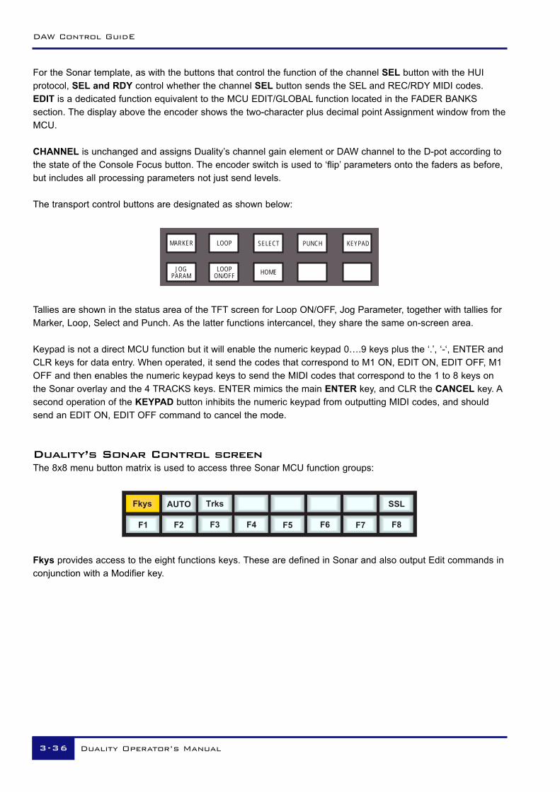
For the Sonar template, as with the buttons that control the function of the channel SEL button with the HUIprotocol, SEL and RDY control whether the channel SEL button sends the SEL and REC/RDY MIDI codes.EDIT is a dedicated function equivalent to the MCU EDIT/GLOBAL function located in the FADER BANKSsection. The display above the encoder shows the two-character plus decimal point Assignment window from theMCU.
CHANNEL is unchanged and assigns Duality’s channel gain element or DAW channel to the D-pot according tothe state of the Console Focus button. The encoder switch is used to ‘flip’ parameters onto the faders as before,but includes all processing parameters not just send levels.
The transport control buttons are designated as shown below:
Tallies are shown in the status area of the TFT screen for Loop ON/OFF, Jog Parameter, together with tallies forMarker, Loop, Select and Punch. As the latter functions intercancel, they share the same on-screen area.
Keypad is not a direct MCU function but it will enable the numeric keypad 0….9 keys plus the ‘.’, ‘-‘, ENTER andCLR keys for data entry. When operated, it send the codes that correspond to M1 ON, EDIT ON, EDIT OFF, M1OFF and then enables the numeric keypad keys to send the MIDI codes that correspond to the 1 to 8 keys onthe Sonar overlay and the 4 TRACKS keys. ENTER mimics the main ENTER key, and CLR the CANCEL key. Asecond operation of the KEYPAD button inhibits the numeric keypad from outputting MIDI codes, and shouldsend an EDIT ON, EDIT OFF command to cancel the mode.
Duality’s Sonar Control screenThe 8x8 menu button matrix is used to access three Sonar MCU function groups:
Fkys provides access to the eight functions keys. These are defined in Sonar and also output Edit commands inconjunction with a Modifier key.
AUTO
F2
Fkys Trks
F1 F4 F5
SSL
F6 F7 F8F3
JOGPARAM
LOOPON/OFF HOME
MARKER LOOP SELECT PUNCH KEYPAD
DAW Control GuidE
3-36 Duality Operator’s Manual

Duality Sonar Control
AUTO calls up three automation functions, Snapshot, Disarm and Offset. The main automation Read/Off key ismapped to a dedicated front panel button.
Trks provides the four TRACKS functions on the bottom row of soft buttons.
AUTO
NMid
Fkys Trks
NAud FitP
SSL
FitA
AUTO
Darm
Fkys Trks
Snap
SSL
Ofst
Duality Operator’s Manual 3-37

Digital Performer TemplateDuality emulates a Mackie Control Unit plus additional Mackie Control Expanders. The Control Surface setupmenu is located in the Digital Performer Setup menu:
Assign Duality’s MIDI ports so that the console faders map correctly to the DAW tracks with the Mackie ControlUnit as the eight channels to the left of the centre section.
Duality’s Digital Performer Control Button Layout
The majority of functions are controlled via dedicated buttons with less reliance than the HUI interface on the8x8 menu button matrix located beneath the TFT screen. When compared to the HUI front panel, the mainchanges are as follows:
Push to Flip
TRACK GROUP
UNDO
SAVESEND
PANUNGRP
AMODE
REDOPLUG-INCHANNEL
EQ
SUSPND
SHIFT CTRLPRESET
RDY SEL
EDIT
EDIT OPTION CMND
CHANNEL
TRACKS
MIXENTER ESCAPE
AUX2METERS
SMPTEBEATS
DAW Control GuidE
3-38 Duality Operator’s Manual

Duality Digital Performer Control
A different function grouping is used to assign parameters the channel D-pots. CHANNEL assigns Duality’schannel gain element or DAW channel to the D-pot according to the state of the Console Focus button. Theencoder switch is used to ‘flip’ parameters onto the faders as before, but includes all processing parameters notjust send levels. The EDIT button is the standard MCU Edit (or Global View) command key, it does not affectoperation of the channel SEL buttons, which can be flipped between the Ready (RDY) and Select (SEL)functions as with the HUI mapping.
The Transport Control buttons are assigned to related transport functions, as with the HUI interface:
On-screen tallies are provided for the Marker function, together with a second tally for the MCU ‘Rude Solo’indicator.
Duality’s Digital Performer Control screenTwo sets of menu buttons can be accessed via the 8x8 soft menu button matrix:
AUTO produces the six Automation mode options.
REC provides the Record setup functions.
AUTO
COUNT
REC
CLICK THRU
SSL
ODUB CLEAR
AUTO
TOUCH
REC
READ OWRT
SSL
TRIMT LATCH TRIML
CYCLERTZ MARKER
SOLOEDITGRID
EXTSYNC
SELECTPUNCH
MEMLINK
PRE/POST
Duality Operator’s Manual 3-39

DAW Control GuidE
3-40 Duality Operator’s Manual

Overview
The Multi-user Total Recall (TR) package is a chargeable option for the Duality console. If not supplied withyour console, please contact your nearest SSL representative for details.
The system uses the channel meter display screens in each bay to give a graphical display of current andstored control settings for all rotary controls, faders and switches on Duality’s channel strips and centre sectionmodules. Controls that are in different positions from the stored values are highlighted in yellow, and may bereset manually to the stored settings. Electronically latched switches such as EQ, Insert, Dynamics and Cutbuttons can be reset to match the stored setup by pressing the fader status button twice. Pressing the SETALL soft key twice will reset all the soft button functions. Pressing the SET SEL key twice will reset the softbuttons on all channels currently selected on the Central Routing Panel.
Each bay screen is used to display the settings for one channel (or the centre section), thus allowing multiplechannels to be reset at the same time.
Stored TR setups can be copied or swapped between channels by holding down the fader status button on thesource channel then pressing the fader status button on the destination channel. If the soft COPY button (seelater) is selected, the source channel settings are copied to the destination channel; if not, the source anddestination channel settings are swapped.
TR setups are saved within Duality’s Projects system and stored locally in Duality’ flash memory. Setups maythen be copied to an appropriate folder on your DAW. See Copying TR Setups to a DAW Folder.
Duality Operator’s Manual 4-1
Total Recall
Section 4 – Total Recall

Total Recall and Projects
Duality uses a logical and intuitive Project-based system within which TR Setups and Mixes (automation data)can be stored and managed. Each Project contains a number of Titles (think of these as songs, tracks, tunesetc.), and each Title contains its own set of TR Setups (and mixes).
The Projects system is accessed using the soft keys on the Master Control Panel in conjunction with displayson TFT screen above:
If you are not familiar with these functions (as used by the Plug-in Editor and other DAW-related functions)please refer to Soft Key Display in Section 3 of this manual.
Project 1 :: Title 1
Select
TR 1 - selected TR 2
TR
Del
SSLAuto
Con
Lnks Daw MiscProj
Store
TR 3TR 4TR 5TR 6
StRt BusM Comp CopyGrpM
Shows currently selected Project and Title
selected indicates which TR Setup is currently being displayed
These functions can be selected using the encoder
switches or the four soft keys directly below
These functions can be selected using the sixteen lower soft keys
Use this control to scroll through lists
Set All Set Sel
Total Recall
4-2 Duality Operator’s Manual

Working with Projects and TitlesAt least one Project and Title must be present before you can store a TR Setup. Select SSL followed by Proj.Now select New Proj and the system will automatically create a new Project and Title; logically these will benamed Project 1 and Title 1 (if no previous projects exist).
If Projects have been previously created, when you press the Proj key, the screen will display a list of existingProjects. Use the lefthand encoder to scroll through the list and when you find the Project you require, pressthe encoder switch (or soft key below the encoder) that represents the Select function. This makes that Projectcurrent (as indicated by the entry being highlighted in yellow, with the word selected after its name) andreveals the Titles in that Project. To create a new Title in a Project, select New Title. Titles and Projects areautomatically numbered in sequence of creation. Select Copy Title to copy the selected Title.
Note that the top line of the display always indicates the current Project and current Title. Use the Select rotarycontrol to scroll through lists of Projects, Titles, etc., and the encoder switch to select them. To return at anytime to the Project list, press the encoder switch for Back.
Saving a TRSetupOnce a new Title has been created, or a previous Title is selected, press TR followed by Store and the currentconsole settings will be saved in the next available TR Setup. New Setups are automatically named TR - nstarting at ‘1’. If a Setup is deleted (see below) then its number will not be re-used. The only exception to this isif all Setups are deleted; the numbering will then restart from ‘1’. Setups are initially saved to Duality’s flashmemory but may be later transferred to your DAW project folder (see Copying TR Setups to a DAW Folder).
Project 1 :: Title 1
Select
Project 1 : : Title 1 - selected
Project 2 : : Title 2
TR
Del
SSLAuto
Con
Lnks Daw MiscProj
Back NewTitle CopyTitle
Duality Operator’s Manual 4-3
Total Recall

Recalling a TRSetup
With TR selected, choose the required Project and Title, and scroll to the required TR Setup (see above). PressSelect and the stored console settings will be displayed on the centre section and bay screens (see nextpage).
Deleting a TRSetupWith TR selected. scroll and Select the setup to be deleted. Hold down the Del soft key and press the Con keyto confirm.
Renaming TR SetupsAutonumbered TR Setups may be named via the Duality Remote application. Please refer to the Dualitysupport pages at http://www.solid-state-logic.com for more details.
Project 1 :: Title 1
Select
TR 1 - selected TR 2
TR
Del
SSLAuto
Con
Lnks Daw MiscProj
Store
TR 3TR 4TR 5TR 6
StRt BusM Comp CopyGrpM
Set All Set Sel
Total Recall
4-4 Duality Operator’s Manual

Total Recall DisplaysAs mentioned before, individual channels are displayed on the TFT screen in that same bay. To switch fromone channel to another within a bay, press the fader status button.
In order to provide maximum clarity, the centre section display is split into four sections, all selected by soft keyfunction is the lower row:
GrpM – Group Control faders
StRt – Four Stereo Return channels
BusM – Track Bus Masters and Aux Bus Masters
Comp – Master Compressor, Mix Reassign Matrix, Stereo Downmix, Foldback Masters, Master Fader(s)
In all cases, controls that are in different positions from their stored values are highlighted in yellow:
Duality Operator’s Manual 4-5
Total Recall

Resetting soft switchesA double press on a fader status button, or Set Sel or Set All, will reset all the non-latching functions on thatchannel strip, selected channel strips, or all channel strips respectively. The non-latching functions are:
• Input section buttons• Dynamics assignment and routing buttons• EQ and Insert buttons• Aux on/off and EFX reassign buttons• Main and Track bus routing• Fader position
All latching switches must be reset manually.
Copying and Swapping settings between channelsStored TR Setups can be copied or swapped between channels by holding down the fader status button on thesource channel then pressing the fader status button on the destination channel. If the COPY soft key isselected, source channel settings are copied to the destination channel; if not, the source and destinationchannel settings are swapped.
Copying TR Setups to a DAW FolderTR setups stored in Duality’s flash memory may be copied to or from a folder on your Mac or PC using theDuality Remote application. Please refer to the Duality support pages at http://www.solid-state-logic.com formore details.
Total Recall
4-6 Duality Operator’s Manual

Automation
OOvveerrvviieeww
Duality’s automation system is a fully featured package, developed from SSL's renowned G and K SeriesUltimation systems, but with a feature set designed specifically for Duality. The classic SSL look and feel,familiar to thousands of engineers worldwide, is utilised to add dynamic fader and cut automation to theconsole. MTC (MIDI Time Code) serves as the mix timeline reference, together with support for MMC (MIDIMachine Control) locate commands to follow non-play speed positional changes from the DAW. Mix data issaved to internal flash memory as part of Duality’s Project system, but may be transferred to your DAW via theDuality Browser, to retain the integrity of the DAW project data.
KKeeyy ffeeaattuurreess• Frame accurate fader and cut automation data• Moving and non moving fader modes• Trim updates• Fader links• Mix Pass history• AutoTakeover• Variable glide times• Fader safe mode• Match and Play Cut automation updates
The system uses the channel bay TFT screens to give a graphical display of fader levels. The centre sectionTFT is used to display the levels of group faders and A, B, C bus master fader levels.
The automation system is a chargeable option for the Duality console. If your console has not been suppliedwith the full automation system, please contact your local SSL representative.
Duality Operator’s Manual 55--11
SSeeccttiioonn 55 –– AAuuttoommaattiioonn
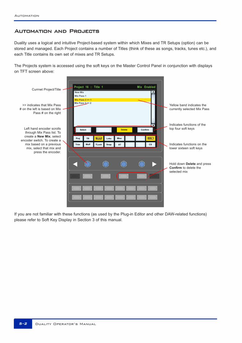
AAuuttoommaattiioonn aanndd PPrroojjeeccttss
Duality uses a logical and intuitive Project-based system within which Mixes and TR Setups (option) can bestored and managed. Each Project contains a number of Titles (think of these as songs, tracks, tunes etc.), andeach Title contains its own set of mixes and TR Setups.
The Projects system is accessed using the soft keys on the Master Control Panel in conjunction with displayson TFT screen above:
If you are not familiar with these functions (as used by the Plug-in Editor and other DAW-related functions)please refer to Soft Key Display in Section 3 of this manual.
Yellow band indicates thecurrently selected Mix Pass
Indicates functions of the top four soft keys
Indicates functions on the lower sixteen soft keys
Hold down Delete and pressConfirm to delete the selected mix
Currnet Project/Title
>> indicates that Mix Pass# on the left is based on Mix
Pass # on the right
Left hand encoder scrolls through Mix Pass list. To create a New Mix, select
encoder switch. To create amix based on a previousmix, select that mix and
press the encoder.
Misc
New Mix
Mix Pass 1
Mix Pass 3 >> 2
Moff
TR
TLockTrim Snap
SSLAuto Lnks
CS
Select Delete Confirm
Misc
AT
Mix Pass 2 >> 1
Mix EnabledProject 16 :: Title 1
Delete
Proj
Automation
55--22 Duality Operator’s Manual

WWoorrkkiinngg wwiitthh PPrroojjeeccttss aanndd TTiittlleessAt least one Project and Title must be present before you can store an automated mix. Select SSL followed byProj. Now select New Proj and the system will automatically create a new Project and Title; logically these willbe named Project 1 and Title 1 (if no previous projects exist).
If Projects have been previously created, when you press the Proj key, the screen will display a list of existingProjects. Use the lefthand encoder to scroll through the list and when you find the Project you require, pressthe encoder switch (or soft key below the encoder) that represents the Select function. This makes that Projectcurrent (as indicated by the entry being highlighted in yellow, with the word selected after its name) andreveals the Titles in that Project. To create a new Title in a Project, select New Title. Titles and Projects areautomatically numbered in sequence of creation. Select Copy Title to copy the selected Title.
Note that the top line of the display always indicates the current Project and current Title. Use the Select rotarycontrol to scroll through lists of Projects, Titles, etc., and the encoder switch to select them. To return at anytime to the Project list, press the encoder switch for Back.
AAccttiivvaattiinngg tthhee AAuuttoommaattiioonn SSyysstteemm
Use the soft keys below the centre section TFT to select SSL then Auto. This calls up the main automationdisplay with its associated soft key menu (see next page).
Select Back New Title Copy Title
Proj TR SSLAuto Lnks Misc
Del Con
Project 1 Title 1 — selectedProject 2 Title 2
Project 1 :: Title 1
Duality Operator’s Manual 55--33
Working with Projects and Titles

OOppeerraattiioonn
LLiisstt MMiixx MMeennuuThe List Mix menu is the main file menu for the automation system, and shows a list of stored Mix Passes.
New Mix Passes are auto-numbered starting at ‘1’. If a Mix Pass is deleted (see below) then its number will notbe re-used. The only exception to this is if all Mix Passes are deleted. The numbering will then restart from ‘1’.Mix Passes can be renamed — see Renaming Mix Passes.
CChhaannggiinngg tthhee sseelleecctteedd MMiixx PPaassssThe lefthand encoder can be used to scroll through the list of Mix Passes. A yellow cursor band indicates whichMix Pass is currently selected for modification. The encoder’s push-push switch can be used to either start aNew Mix, or select a previous Mix Pass.
DDeelleettiinngg MMiixx PPaasssseessMix Passes can be deleted from memory by selecting the Mix Pass you wish to delete, holding down theDelete soft key and pressing the Confirm soft key.
Trim Moff TLock Snap AT
Proj TR Lnks Misc
Select Delete
Project 16 :: Title 1
CS
Auto SSL
NEW MIXMix Pass 1Mix Pass 2 1Mix Pass 3 2
Mix Enabled
Automation
55--44 Duality Operator’s Manual

CCrreeaattiinngg AA NNeeww MMiixx PPaassssTo create a new automated Mix Pass, press List Mix to access the screen shown below, use the lefthandencoder to highlight the New Mix entry.
Now press the encoder switch to select the NewMix Setup page (see below). All the channel faderswill enter Absolute mode, as indicated by a redLED next to each fader.
The DAW should be positioned a few frames earlier than the required starting point, to allow the mix system tolock to the incoming timecode.
The current automation status for each channel is displayed in the scribble strip above the fader, replacing thestandard ‘Fader ##’ label. Faders can be toggled between Absolute and Manual using the fader status buttonlocated next to the fader, or globally using the FSM (Fader Status Master) soft key (see below).
New Mix Pass modes for faders
Absolute mode: Red LED. All automated movesare written at the current fader position.
Manual mode: No LEDs. The fader operates as amonitor fader only, ie. no information will be writtento memory.
Pressing the CANCEL button (in the ‘AUTOMATION’ group above the ‘TRANSPORT’ buttons) will return you tothe List Mix page. See Dedicated Automation Buttons for more information.
Mix Enabled
Misc
Moff
TR
TLockTrim Snap AT
SSL
Execute FSM
Auto
CS
***NEW MIX***you may adjust status now.Press Execute to continue
Cancel
Lnks
Project 16 :: Title 1
Misc
Trim Moff TLock Snap AT
Proj TR Lnks Misc
Select Delete
Project 16 :: Title 1
CS
Auto SSL
NEW MIX
Mix Enabled
Duality Operator’s Manual 55--55
Creating a New Mix pass

To start a mix, press the Execute key (how many of you remember this from SSL’s renowned E and G SeriesComputers?). Check that timecode is turning over on the screen — if Duality is not reading MTC, it will notrecord any mix data.
The screen flips to show a bargraph display of fader levels for the eight centre section group master faders andthe three A, B, C mix Bus Master faders. Channel fader levels are shown on the channel bay TFT displays.
The system saves a global ‘static’ reference mix ofthe fader levels and cut status when the Executekey is pressed. This is useful because it allowsyou to locate before the start of the mix andrecover your original levels (ie. reference mix).
Also, if you are writing automation in a section thathad no previous mix data, when you drop out ofwrite the faders will return to their original levels.
MMiixx RRuunnnniinnggPress Play on the DAW to move forward, and as soon as the automation system has locked to the MIDItimecode (MTC), the mix status display will indicate ‘Mix Running’. Simply adjust the faders and press cutswitches to write your mix as required, and the fader moves and cut data will be recorded. The DAW may betoggled freely between Stop and Play, and if Fast Forward is used, or the DAW is located forward, theautomation data will be extended to the new position when the DAW returns to Play.
To abort the current mix at any time, press the Discard soft key or the dedicated DISCARD button in the‘AUTOMATION’ group above the ‘TRANSPORT’ buttons. To save the current mix to flash memory and return tothe Mix List, press the END button. For more on the other buttons in this group, see Dedicated AutomationButtons.
MMiixx RReevviieewwAt any time you can rewind the system, and as soon as the DAW is located to an earlier time and valid MTC ora MMC locate position command is received, the mix system enters ‘Mix Review’. All faders will switch toReplay status (all LEDs are off). This operation is known as a ‘rollback’.
Project 1 :: Title 2
AutoAutoAutoAutoAutoAutoAutoAutoAuto AutoAuto
Mix Review 23
Misc
Moff
TR
TLockTrim Snap AT
SSLAuto
CS
Lnks Misc
End DiscardRevise Join
0 0 : 0 2 : 1 2 : 23 Project 1 :: Title 2
End Discard
AutoAutoAutoAutoAutoAutoAutoAutoAuto AutoAuto
Misc
Moff
TR
TLockTrim Snap AT
SSLAuto
CS
Lnks Misc
Revise Join
0 0 : 0 2 : 1 2 : 23 MIX RUNNING
Automation
55--66 Duality Operator’s Manual

Mix Running — displayed while writing newautomation data.
Mix Review — displayed as soon as you roll backand when you play forward to replay previousautomation data.
The number after Mix Review (in this case 23)indicates the number of times you have rolled backin the current mix.
When the DAW returns to Play, previously written automation data is replayed. If no faders are returned towrite, all faders in write at the start of the mix will drop back into write at the point at which the DAW wasrewound (the ‘rollback point’, and the mix status will return to Mix Running. Whilst in Mix Review you mayrollback as many times as required to allow the mix to be built up fader by fader. Each time a rollback takesplace, the rollback counter in the mix status display increments. Faders in write at a rollback point willautomatically switch to write when the system plays through the rollback point.
DDeeddiiccaatteedd AAuuttoommaattiioonn BBuuttttoonnssA group of dedicated automation buttons are provided in the centre section, just above the transport buttons:
The CANCEL button is used to cancel a mix and return to the Mix List page. Pressing the END button savesthe current mix to flash memory and also returns you to the Mix List.
Pressing the ALL REPLAY button simply puts all faders and cuts, that are in write, into Replay status, which isuseful for flipping all the currently recording controls into Replay without stopping or rewinding.
The other buttons in this group are described on the following pages.
TRANSPORT
AUTOMATION
TRIM MOTORSOFF
TRIMLOK
SNAP AUTOT/OVER
DISCARD
END REVISE JOIN ALLREPLAY CANCEL
STOP PLAY RECORD
Project 1 :: Title 2
AutoAutoAutoAutoAutoAutoAutoAutoAuto AutoAuto
Mix Review 23
Misc
Moff
TR
TLockTrim Snap AT
SSLAuto
CS
Lnks Misc
End DiscardRevise Join
0 0 : 0 2 : 1 2 : 23
Duality Operator’s Manual 55--77
Dedicated Automation Buttons

JJooiinn aanndd RReevviisseeAt any time during Mix Review, the JOIN button can be used to switch all channels that were in write at the lastrollback point, back into write at the levels or state they were at the rollback point (got that?). This is useful, forexample, when balancing levels in a chorus. Once you have achieved the right balance, simply rollback beforethe start of the chorus, go into Play, hit JOIN at the start of the chorus and the levels will punch in at thebalance set before rollback, with all channels back in write.
The REVISE button has a similar action except that all channels in write at the rollback point are returned towrite at their current mix position. This is useful when you are mixing a particular section, but have made asmall mistake. Just rollback before the mistake, hit REVISE and channels will immediately go into write at thecurrent fader level, allowing you to overwrite the mistake.
Here is an exaggerated graphic representation of both functions:
Multiple rollback memories are supported so that successive operations of JOIN or REVISE can return differentsets of faders back to write, if multiple rollbacks have taken place:
Mix Review Mix Running
Pass 4
Pass 3 (Channels 7-8 in Absolute)
Pass 2 (Channels 1-6 in Absolute)
Pass 1 (All channels in Absolute)
JOINRollbackPoint 2
RollbackPoint 1
Global Rollback Point
Time
Start Rollback pointPress Join Key
Will jump to rollback point level
Original Automation
New Automation
JOIN FUNCTION
Start Rollback pointPress Join Key
Will jump to rollback point leveland start writing new data
JOIN FUNCTION
Start Rollback point
Will start writing new data from current level
REVISE FUNCTION
Press Join KeyStart Press the Join Key Rollback Point Start Press the Revise Key Rollback Point
JOIN FUNCTION Will jump to rollback level whenJoin is pressed and write new data
REVISE FUNCTION Will stay at current mix level when Revise is pressed and write newdata
Original AutomationNew Automation
Automation
55--88 Duality Operator’s Manual

To return all faders to Absolute, use the JOIN or REVISE buttons until the ‘global’ rollback memory is reached,at which point all faders will return to write either at their current position (REVISE), or at the levels they had atthe global rollback point (JOIN).
DDiissccaarrddIf the system is in play or stopped following a rollback operation, pressing the Discard soft key, or thededicated DISCARD button, clears any data recorded since the start of the rollback pass, forces all channels inwrite back to the read/write state they were in prior to the rollback operation at the point in time the Discardfunction was operated, and restores the active rollback points from the previous pass.
UUppddaattiinngg aa MMiixx PPaassss
To update a Mix Pass, first select the desired mixon the List Mix page by scrolling with the lefthandrotary encoder and pressing the encoder switch.
***Mix Pass #*** will be displayed (see left), andthe selected mix will now become the referencemix.
The FSM soft key will toggle all faders betweenAbsolute and Replay or Trim and Replay (seebelow for more on Trim status).
PPrrootteeccttiioonn MMooddeessWhen you update a previously stored mix, three different data protection modes become available: Auto, Safeand Manual.
Auto If moves need to be rewritten from scratch, faders can be dropped into write at thestart of a mix by pressing the fader status button. Alternatively, they can bedropped into write once the mix is running, either by using the fader touch sensor(motor faders on), or by pressing the fader status button.
Safe Existing fader and cut automation data can be protected with the Safe option.When channels are in Safe, automation data is replayed but no data can bewritten to these channels.
Manual Existing automation data is protected and the fader and cut switch act directly onthe channel audio. No automation is written or played back.
To select the different protection modes, press the ASM soft key, and then press the fader status button on thedesired channel to toggle between the modes, as displayed in the scribble strips above the faders. To select amode globally, press the ASM key and then press the FSM key until the required mode is selected.
Mix Enabled
***NEW MIX***you may adjust status now.Press Execute to continue
Execute FSM Cancel
Project 16 :: Title 1
Misc
Moff
TR
TLockTrim Snap AT
SSLAuto
CS
Lnks Misc
Mix Enabled
Execute FSM Cancel
Project 16 :: Title 1
Misc
Moff
TR
TLockTrim Snap AT
SSLAuto
CS
Lnks Misc
MIX PASS 1:you may adjust status nowPress Execute to continue
ASM
Duality Operator’s Manual 55--99
Updating a Mix Pass

AAuuttoommaattiioonn OOppttiioonnss
TTrriimmTrim status (AKA Relative) originates from VCA (non-moving fader) automation systems and uses the fader toadd or subtract level from existing moves. It achieved this by setting up a ‘null’ fader position and then anysubsequent moves trim the existing data by the amount of positive or negative change from the null point. Trimis useful, for example, when you have a automated a complex vocal line that needs raising by 2dB. Ratherthan trying to re-write all the moves again, simply rollback, hit the TRIM button (in the ‘AUTOMATION’ group),and then move the fader up by 2dB. Locate to the end of the vocal line that needs this level increase, andpress the END button to commit the trim to a Mix Pass.
The red (upper) line in this illustration shows the effect ofthe trim.
Once the TRIM function is active (button is lit), faders can be put into Trim status at anytime in Mix Running orin Mix Review, except during the first pass of a new mix. Trim is indicated by the green status LED next to thefader. When Trim is available at the start of an Update Mix, the FSM soft key will toggle all faders betweenReplay and Trim.
Trim can be used with the fader motors on or off (see Motors Off). If the motors are on, the null point will bethe fader position prior to selecting the fader status button, or touching the fader. If the motors are off, the fadercan be positioned at any suitable reference point on the scale, before entering Trim update status by pressingthe fader status button. Duality’s automation system features SSL’s ‘auto-nulling’ feature so that each time Trimis re-enabled, a new null point is set. When writing a trimmed move, the trim value in dBs is displayed in thescribble strip above the fader.
Using the Autotakeover and Snap functions (see below) in conjunction with a Trim update allows a seamlessor smooth return to the stored mix data.
When Join is used with faders in Trim at the rollback point, any Trim offset will be retained and written from thepoint that the JOIN button is pressed. Revise returns any fader in Trim at the rollback point back to write butwith a new null point to avoid a level jump.
New Automation
Original Automation
Automation
55--1100 Duality Operator’s Manual

TTrriimm LLoocckkTrim Lock (only available in ‘Motors Off’ mode — see below) defeats the auto nulling feature provided for thestandard Trim function, and ‘locks’ the null point to the position that the fader was in when Trim was firstenabled in the current Mix Pass. This enables a defined trim offset to be repeatedly punched in and outthroughout subsequent Mix Passes.
Select this function by pressing the TRIM LOK button in the ‘AUTOMATION’ group. When TRIM LOK isdeselected, any stored nulled points are cleared. AutoTakeover can be used when Trim Lock is active,however Snap and Trim Lock are mutually exclusive; selecting one deselects the other, and vice versa.
As an example of Trim Lock, how about bringing up the level of some of guitar licks in a track. If Trim is used inwith Snap mode, the fader can be raised and let go repeatedly, returning to the previous level. However, it isdifficult to get an identical increase in level each time, when you do this manually. If you select TRIM LOK, thereference value will be set, and the fader will be moved to the correct raised level. Every time you press thefader status button, the fader will jump to that level and, when pressed again, it will return to the referencevalue. Note that there will be no glide times but the maximum value will be identical each time.
Fader moved
Fader released
Level not exact
Status key pressed
Status key pressed again
Level is exact
TRIM IN SNAP MODE
TRIM WITH TLOCK
Duality Operator’s Manual 55--1111
Trim Lock

MMoottoorrss OOffffThis mode suspends the motorised playback of mix data via the moving faders. In ‘Motors Off’ — select theMOTORS OFF button in the ‘AUTOMATION’ group — the faders emulate a VCA automation system. MOTORSOFF automatically activates the Fader Links SuspdAll function (see later).
SSnnaapp MMooddeeSnap mode uses the fader touch sensor to control both the start and end of a fader update — for fast hands-on changes to mix levels. When the fader is released, it ramps back to the previous mix level at a user-determined rate (see Glide Frames), then returns to Replay.
Snap mode can be overridden on any channel by pressing the fader button while still touching the fader knob.On releasing the fader, the channel while stay in Absolute or Trim until a subsequent fader button press returnsthe channel to Replay. This write/replay transition will include the ramped Snap glide if enabled in the setupmenu (see Glide Frames for more detail).
AAuuttooTTaakkeeoovveerrTo avoid a level jump when dropping out of write, AutoTakeover introduces nulling indicators in the scribblestrip to display the direction to move the fader to match the underlying mix level. When the fader crosses thecurrent mix level, it is automatically returned to Replay and disconnected from the audio gain element. Thefader returns to following the mix data as soon as it is physically released.
New Automation
Original Automation
End Point – when fader is released
Scribble strip indicates direction to move fader back to its original position
Manual glide turns automation off once the original level is matched
Start Point when fade is first touched
New Automation
Original Automation
Start Point when fader first touched
End Point – when fader is released it ramps back to
the previous mix level
Glide time can be set in the Setup menu
Automation
55--1122 Duality Operator’s Manual

CCuutt AAuuttoommaattiioonnPressing a CUT button will toggle its state and automatically start writing data. The Cut can be returned toReplay either by rolling back or by selecting the Play button on the fader, and then pressing the CUT buttonagain.
The state of a channel Cut is stored separately from the fader data. Cut data is stored regardless of the currentfader status unless the channel Safe mode is selected. Whenever a channel or group CUT function is in write,the red rec LED on the fader will light.
Pressing the fader-based Match button, followed by the CUT button, drops that Cut into write without changingthe current state of the Cut. Match and Play are mutually exclusive. If one is active, selecting the alternatefunction cancels the first one.
UUssiinngg MMaattcchh aanndd PPllaayy ttoo ccoorrrreecctt aa CCuuttIf you have made a cut in the wrong place, simply move the DAW to a position before the error, go into Play,select Match and press the CUT button to automatically drop into write without changing the stored state of theCut at that point (see diagram below). When the Cut has been overwritten, select Play and press the CUTbutton again to return to the previous automation state.
CUT UNCUT CUT UNCUT
ERROR
MATCH & CUT PLAY & CUT
Duality Operator’s Manual 55--1133
Cut Automation

CCooppyy aanndd SSwwaappCopy and Swap (CS in the Auto menu) are used to interchange or transfer mix data between channels. Therequired function is selected by pressing the CS soft key to toggle between the two modes.
Copy is displayed as Cpy, Swap as Swp. Select the function required, hold down the source channel faderbutton while you press the destination channel fader button. While the fader buttons are active, ‘src’ and ‘dest’will be displayed in the scribble strip above each fader. Note that you can only Copy or Swap automation datawhen the system is in Mix Running or Mix Review.
The Copy function copies data to a single channel only. To copy the same data to multiple channels, repeat theCopy operation as many times as required.
The mix data generated by a Copy or Swap is not saved until the current Mix Pass is ‘Ended’.
Glide Frames — Sets the ramp time in frames for Snap mode. The range is from 0 (no glide) to 255 (10second glide).
Rollback Threshold frames — Sets the number of consecutive, decrementing, frames that the systems needsto see to determine if a rollback has taken place. The range is 2-10; the default is 2 frames. Increase asrequired if a rollback occurs when you stop the timecode master.
Automation
55--1144 Duality Operator’s Manual

FFaaddeerr LLiinnkkssFader Links are a useful method of ganging channels without the complexity of a Master/Slave style groupingsystem. With a Fader Link, operating any fader, or a CUT, SOLO or fader button will apply the same action toall the channels in the link.
Faders retain any existing level offsets, provided no fader in the link reaches the upper or lower extremes ofthe fader scale. If any member of a link reaches the end of its physical travel, no member of the link can movebeyond this point. To access Fader Links, press the Lnks soft key next to the Auto key.
CCrreeaattiinngg aa NNeeww LLiinnkk
To set up a new link, scroll to New Link and pressthe D-pot push switch. This will create a new entryin the list suffixed with a number. This entry will beautomatically highlighted, and faders can be addedto (or removed from) the link by pressing theirfader buttons. Link numbers are shown in thefader scribble strip and the red fader status LEDSwill indicate those faders in the currently selectedlink.
To adjust balance of a link, hold one fader whilstmoving another. This automatically isolates thesecond fader from the link whilst the remainingfaders continue to track the first fader touched.
As far as the automation system is concerned, moving one fader in a link puts all the faders in the link intowrite. Links can be dissolved at any time, but all the automation data will still play out correctly.
To edit any existing links, scroll to and select the link. Channels can be added or removed as described above.
SSuussppddSSeell//SSuussppddAAllllLinks can be globally or individually suspended at anytime. A link that is suspended will allow you to move allthe faders in the link independently. If a link is highlighted, then the SuspdSel key will deactivate the selectedlink and ‘suspended’ will be shown next to the link number. SuspdAll suspends all links in the list. The ‘MotorsOff’ function automatically activates the SuspdAll function.
DDeelleettiinngg LLiinnkkssTo delete a link, select and highlight it, then use the Delete and Confirm keys.
TR Auto SSL
NEW MIX
SuspdSel Delete
Project 16 :: Title 1
NEW MIX
Fader Links
FADER LINK 1
FADER LINK 3FADER LINK 2
SuspdAll Confirm
Proj Links Misc
Duality Operator’s Manual 55--1155
Fader Links

SSaavviinngg MMiixx PPaasssseess ttoo yyoouurr DDAAWW PPrroojjeeccttInitially, Mix Passes will be held safely in Duality’s internal flash memory when you ‘End’ a mix, but may becopied to or from a folder on your Mac or PC using the Duality Remote application. Please refer to the Dualitysupport pages at http://www.solid-state-logic.com for more details.
Automation
55--1166 Duality Operator’s Manual

PPrroo TToooollss SSeettuupp NNootteessTo set up timecode generation: Windows/Show Session Setup
Select the MTC option and select the port on the MIDI interface that is connected to Duality’s Port 8 MIDI IN.Also select the timecode rate for the session and the session start time.
It is essential to make a note of the timecode standard that was used for a particular Duality mixing project.The automation system automatically detects the timecode standard from the incoming MTC messages. It willquite happily attempt to play out stored mix data to incoming timecode with a different frame rate, but this will
result in small but potentially annoying timing errors in automation playback.
To set up MMC locates: Setups/Peripherals
Duality Operator’s Manual 55--1177
Pro Tools Setup

Enable MIDI Machine Control and select the Port on the MIDI Interface that is connected to Duality’s Port 8MIDI IN. Leave the ID as 127 (this sends to all connected devices).
Setups/Preferences
Enable the top two options in the lefthand list (see above). This ensures that the MMC locate messages aretransmitted correctly from Pro Tools.
Automation
55--1188 Duality Operator’s Manual

Finally: Setup/Preferences
When mixing with Duality, it is advisable to enable the two options in the lefthand list (see above). This ensuresthat a Rollback will occur following a locate or rewind operation in Pro Tools. If these options are not enabled,then Pro Tools does not send a locate command following a Stop command even though the desk counter willshow the position that Play last occurred from, and where Play will resume from. The automation Rollback willthen occur when the system is returned to play, which can be disconcerting. Enabling the option ensures thatRollbacks occur prior to entering Play but at the expense of defeating the Pro Tools feature of automaticallyreturning to the last Play position following the Stop command.
Duality Operator’s Manual 55--1199
Pro Tools Setup

Automation
55--2200 Duality Operator’s Manual

Section 6 – Logictivity – Duality Remote Browser
IntroductionThe Duality console allows the use of a remote application; the Logictivity based Duality Remote Browser, whichprovides a one-stop external solution for archiving and retrieval of automation and Total Recall data along withsession management functions. Users can also use this browser to add Eyeconix images to their consoles TFTscreens, allowing at a glance identification of track sources.
Duality RemoteFirst download and install the Duality Remote application on the Mac or PC you intend to manage your Dualityfrom.
Installing your Duality Browser
If you do not have the remote application, please download the latest version from:
www.solid-state-logic.com/plus/utilities.html
You must be registered to enter this area so please take the time to do so.
The files are listed under Duality Java Applications
There are separate files for PC and Macintosh computers.
The PC version is a .zip archive, so simply double click to unzip it.
The Macintosh version is a .dmg file, which can be extracted by double clicking also.
Once successfully unpacked you should then have a stand alone java application called ‘Solid State LogicDuality’.
A note on Java
The Duality Logictivity Browser application is Java based and compatible with Mac OS 10.4 and above andWindows 2000, XP and Vista.
If you do not have java on your computer then please visit and download it from. www.java.com
Duality Remote requires Java Runtime Environment Version 5.0, or above.
The above URL will also verify your computers currently installed Java environment.
The console normally uses a DHCP server to assign it’s IP address. The computer and console should beconnected to a network with a DHCP server. If you wish to use a fixed IP address this can be set using theterminal diagnostic port on the rear of the console. See page 6-2 for details.
Duality Operator’s Manual 6-1

Logictivity
Duality Operator’s Manual6-2
CONNECTING DUALITY TO YOUR COMPUTERDuality is the first analogue console to feature an IP address. This allows any standard personal computer (Macor PC) to connect to your console.
To do this you will need to establish a small local Network. It is recommended that you use a DHCP hub, alsoknown as a standard Ethernet router, which can dynamically allocate an IP address to your Duality console.
These hubs are commercially available from most computer shops and suppliers. We do not recommendspecific products due to variance in supply in different international territories.
Refer to the hub’s installation guide to ensure that it is configured for DHCP.
Then simply connect your personal computer and the Duality console to the hub via the console’s network portand the usual network port on your personal computer. You will require 2x standard CAT-5 or Ethernet twistedpair cables to do this.
To verify that an address has been assigned to your Duality console go to SSL>Misc>Net and you should seethe assigned address (10.1.3.222 for example).
Setting a Fixed IP AddressThe console IP address can be fixed using the diagnostic terminal port on the rear of the console. You will needa PC or Mac running terminal emulator software. Connect the PC serial port to Serial 2 on the rear of theconsole using a pin to pin 9 way ‘D’ type extension cable (male to female).
Set the terminal as follows: Baud rate 192008 data bitsNo parityNo start bit1 stop bitFlow control Xon/Xoff
Press the ‘Return’ key (<CR>) and the terminal window should echo a ‘>’ if communication is established. To fixthe IP address type the following:
ip <CR>
setip nnn nnn nnn nnn <CR> Enter the IP address where ‘nnn nnn nnn nnn’ is the IP address, eg. ‘101 1 10’
setmask nnn nnn nnn nnn <CR> Enter the network mask eg. ‘255 255 255 0’. Note that this will dependon your network and should match other devices local to the console.
setgate nnn nnn nnn nnn <CR> Enter the gateway address eg. ‘10 1 1 1’
usefixed <CR>
Finally, reboot the console and check the assigned IP address in the SSL/Misc/Net page.

Connecting to DualityWhen you launch Duality Remote you will be presented with a rather dull looking grey form. Click on the Findbox in the top right of the form and select your console from the popup list of consoles (which will normally onlycontain one entry) - see below. Then click Select. The popup will close and the Project page will be populated.
Any existing data stored on your console should now be visible in the browser. The currently selected Projectand Title will be displayed in the top left hand corner along with the consoles serial number.
The following tabs will be visible:
PROJECTS:This shows a traditional “tree” file structure and architecture listing Projects stored on the console.
NOTES:Here you can enter Project and Title information and also session notes.
MIXES:A list of Mixes associated with the currently selected Title.
TOTAL RECALL:A list of Total Recall data stored for the currently selected Title.
CHANS 1-24, 25-48 etc.:These fields allow you to enter names for the TFT Channel displays on the console and also assign Eyconiximages.
EXTS NAMES:Allows you to rename the Ext A and B sources. These will appear on your consoles monitor selection.
MISC:This contains some additional information and functions.
The SYNC button will refresh your Browser with any recently stored local data (i.e. on the flash SD card) fromthe Duality console.
To rename an item, simply right click (PC) or use ‘<Ctrl> click’ (Mac
Duality Operator’s Manual 6-3

Project TabAfter launching Duality Remote the Projects tab will appear – see below.
Clicking on the ‘+’ (or ‘�’) sign to the left of the Projects folder will list all available Projects. Clicking the ‘+’ (or‘�’) sign to the left of one of the listed Projects will expand the folder to show the Titles contained in the folder.Expanding a Title folder will show folders for Mix Passes, Total Recalls and any Eyeconix icons used in thatTitle.
Copying Titles, Total Recall and Mix data between Projects
To copy data between folders select and drag the file or folder you wish to copy to your destination folder. Notethat any existing names will not be kept when copying data between projects or titles – the system willautomatically name the copy with the next available default name (e.g Mix 5).
You can copy complete Titles to Projects and copy Mixes and TR setups between Mix Passes and Total Recallfolders. You cannot copy entire Mix Pass or Total Recall folders.
You will be asked for confirmation when copying data and given the opportunity to cancel.
Logictivity
Duality Operator’s Manual6-4

Renaming Projects, Titles, Mixes or Total Recall SetupsIn order to rename a file or folder, right click (or ‘<Ctrl> click’) the file or folder and select ‘Rename’. Enter thename then click on OK.
Backing up a ProjectTo create a .zip backup of the project, right click (or ‘<Ctrl> click’) on the project name and select ‘BackupProject’. A popup will appear asking for a name and location to which to save the .zip file.
Restoring a ProjectTo restore a .zip backup of a project, right click (or ‘<Ctrl> click’), on a Project folder, then select ‘RestoreProject’. A popup will appear asking for the name of the .zip file to restore to the Projects list – click on thedesired project to select it. The restored project will be restored under it’s original name followed by “(restoredproject)”; Projects with the same name will not be overwritten.
Notes TabThe Notes tab provides a space for storing information about the current Project and Title. Any of the entries,including Project and Title names can be updated by clicking in the appropriate box and entering text from thekeyboard.Please note that only the ‘Name’ fields for Project and Title will be visible from the console.
The data fields can accept up to 32 characters of information apart from the two ‘Notes’ fields which can acceptup to 256 characters.
Duality Operator’s Manual 6-5

Channel TabsThe Chans 1 to 24, Chans 25 to 48, Chans 49 to 72 and Chans 73 to 96 tabs allow the user to assign smallimages (eyecons) and names to console channels. The system is supplied with a number of standard eyecons.Others can be added by the user – see below.
To insert a picture onto the channel’s Eyeconix meter section, click on the required graphic in the left hand listand drag it to the rectangle under the channel name.
To rename a channels TFT scribble strip display, simply click on the name (eg. ‘Fader 1’) and enter the requiredname.
To add more images to the Eyeconix list, select the Add button at the bottom of the left hand list and select therequired graphic from the resulting pop-up. Supported file formats are: gif, jpeg, tiff, and png – the Eyeconixsoftware will automatically resize any picture brought into the browser interface.
All eyecons are stored in a dedicated folder on the removable flash card in the console. A copy of the eyeconsused in each Title is stored in the Eyeconix folder inside the Title folder. This ensures that Project archives willautomatically include all the eyecons used in that Project.
To delete a graphic from the list, highlight it and select Delete. Note that if you delete one of the system eyeconsit will be restored next time you restart your Duality.
Logictivity
Duality Operator’s Manual6-6

MixesThis page shows a list of Mixes associated with the currently selected Title.
It is also possible to delete and rename Mixes in this window. In order to rename a Mix, right click(or ‘<Ctrl> click’) the file or folder and select ‘Rename’. Enter the name then click on OK.To delete a Mix, right click (or ‘<Ctrl> click’) on the Mix name and select ‘Delete’.
Duality Operator’s Manual 6-7

Total RecallHere you can rename and delete any Total Recall data from the currently selected Title. In order to rename a fileor folder, right click (or ‘<Ctrl> click’) the file or folder and select ‘Rename Project’. Enter the name then click onOK. To delete a Total Recall setup, right click (or ‘<Ctrl> click’) and select ‘Delete’.
Logictivity
Duality Operator’s Manual6-8
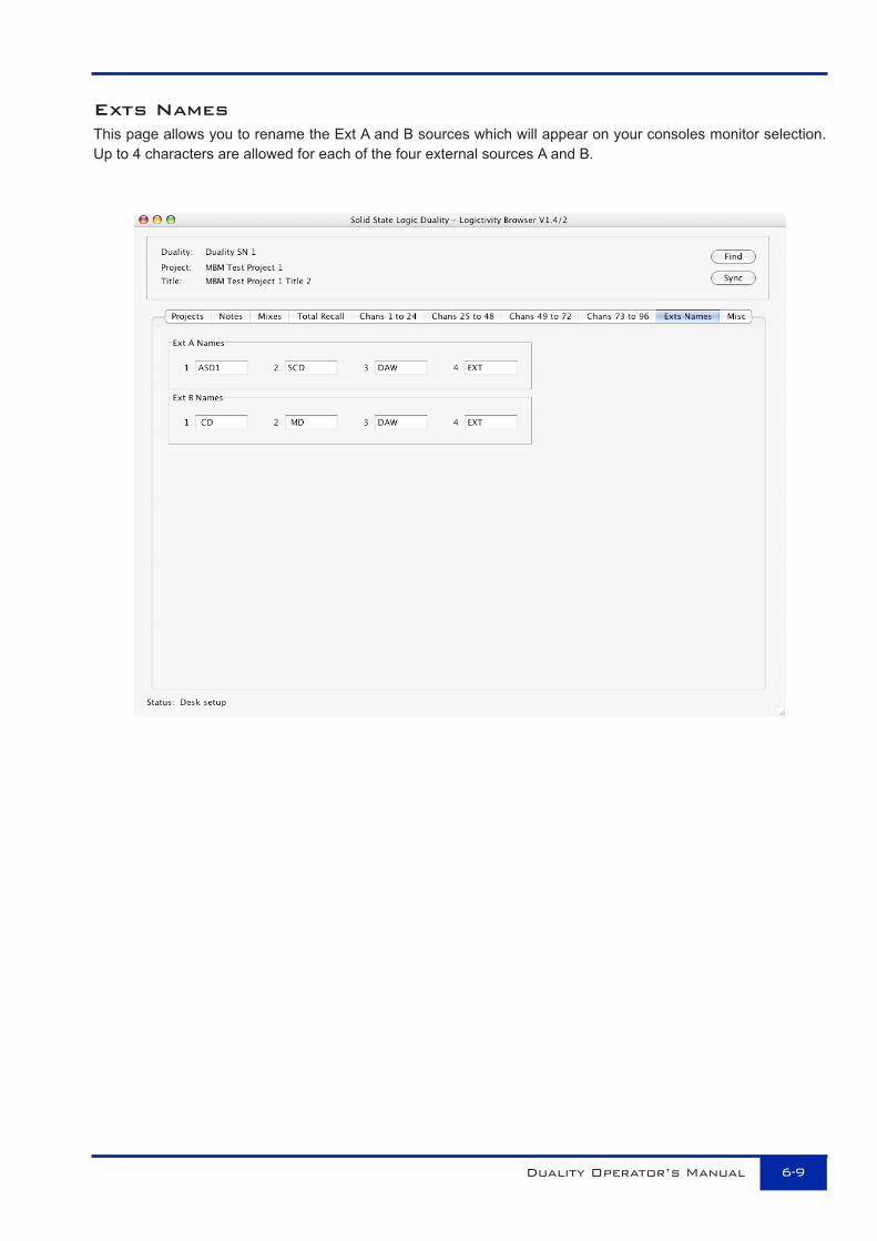
Exts NamesThis page allows you to rename the Ext A and B sources which will appear on your consoles monitor selection.Up to 4 characters are allowed for each of the four external sources A and B.
Duality Operator’s Manual 6-9

Misc TabThe Misc tab shows the software versions of both the Duality console and the Duality Remote software andallows the desk clock to be set.
Time and Date. Clicking on this box will sync the Duality to the time and date on your computer. This should bedone after you first install the console (or when you first install Duality Remote V1.4). You cannot currently viewthis time data but mixes and total recall setups will be time and date stamped.
The last item provides a direct link to the Solid State Logic website.
Logictivity
Duality Operator’s Manual6-10

DualityOperator's
Manual
82S6DUA20C
Solid State LogicS O U N D | | V I S I O N
DualityOperator's
Manual
82S6DUA20C
Solid State LogicS O U N D | | V I S I O N


![A DUALITY THEORY FOR UNBOUNDED HERMITIAN ...arXiv:0904.1699v1 [math-ph] 10 Apr 2009 A DUALITY THEORY FOR UNBOUNDED HERMITIAN OPERATORS IN HILBERT SPACE PALLE E.T. JORGENSEN University](https://static.fdocuments.net/doc/165x107/6091f0f5f873bc2d98512815/a-duality-theory-for-unbounded-hermitian-arxiv09041699v1-math-ph-10-apr.jpg)