DOPAS Work Package 3 - Deliverable 3.1 WP3 FSS ...€¦ · WP3, WP4 and WP5 are led by SKB...
43
Deliverable n° D3.1 Version A 1/43 Dissemination level: PU Date of issue of this report: 18.11.16 DOPAS Work Package 3 - Deliverable 3.1 WP3 FSS Construction Summary Report Start date of the project: September 2012 Duration: 48 months Grant Agreement No: 323273 Authors: Jean-Michel Bosgiraud and Régis Foin (Andra) Date of preparation: 18 November 2016 Version status: Version A Project co-funded by the European Commission under the Euratom Research and Training Programme on Nuclear Energy within the Seventh Framework Programme Dissemination Level PU Public X PP Restricted to other programme participants (including the Commission Services) RE Restricted to a group specified by the partners of the DOPAS project CO Confidential, only for partners of the DOPAS project
Transcript of DOPAS Work Package 3 - Deliverable 3.1 WP3 FSS ...€¦ · WP3, WP4 and WP5 are led by SKB...

Deliverable n° D3.1 Version A 1/43Dissemination level: PU
Date of issue of this report: 18.11.16
DOPAS Work Package 3 - Deliverable 3.1WP3 FSS Construction Summary Report
Start date of the project: September 2012 Duration: 48 months
Grant Agreement No: 323273
Authors: Jean-Michel Bosgiraud and Régis Foin (Andra)Date of preparation: 18 November 2016
Version status: Version A
Project co-funded by the European Commission under the Euratom Research and Training Programme onNuclear Energy within the Seventh Framework Programme
Dissemination LevelPU Public XPP Restricted to other programme participants (including the Commission Services)RE Restricted to a group specified by the partners of the DOPAS projectCO Confidential, only for partners of the DOPAS project

Deliverable n° D3.1 Version A 2/43Dissemination level: PU
Date of issue of this report: 18.11.16
History Chart
Type of revision Document name Partner DateDocument in version 1 forinternal review
WP3 FSS construction SummaryReport
Andra 31.10.2016
Document in version A forapproval by DOPASCoordinator
WP3 FSS construction SummaryReport
Andra 18.11.2016
REVIEW/OTHER COMMENTS:The report was internally reviewed by Andra and later submitted in version A for approvalby the DOPAS Coordinator (Johanna Hansen for POSIVA).
APPROVED FOR SUBMISSION:Johanna Hansen (POSIVA) 18.11.2016
Scope Deliverable n°D3.1 (WP3) Version: 1
Type/No. Report D3.1 Total pages 43
Title WP3 FSS construction SummaryReport
Articles: 5

DOPAS D3.1 Version A i 18 November 2016
Executive Summary
Report BackgroundThe Full-Scale Demonstration of Plugs and Seals (DOPAS) Project is a EuropeanCommission (EC) programme of work jointly funded by the Euratom Seventh FrameworkProgramme and European nuclear waste management organisations (WMOs). The DOPASProject is running in the period September 2012- August 2016. Fourteen European WMOsand research and consultancy institutions from eight European countries are participating inthe DOPAS Project. The Project is coordinated by Posiva (Finland). A set of full-scaleexperiments, laboratory tests, and performance assessment studies of plugs and seals forgeological repositories are being carried out in the course of the project.The DOPAS Project aims to improve the industrial feasibility of full-scale plugs and seals,the measurement of their characteristics, the control of their behaviour in repositoryconditions, and their performance with respect to safety objectives. This work does not startfrom a clean slate, since previous works (at a lower scale) were anteriorly implemented bysome of the participants. For example, the works carried out in the FP6 ESDRED and FP7LUCOEX projects are some of the reference works on which the DOPAS work is partlybuilding on.
The DOPAS Project is being carried out in seven Work Packages (WPs). WP1 includesproject management and coordination and is led by Posiva, Finland. WP2, WP3, WP4 andWP5 address, respectively, the design basis, construction, compliance testing, andperformance assessment modelling of five full-scale experiments and laboratory tests. WP2,WP3, WP4 and WP5 are led by SKB (Sweden), Andra (France), RWM (United Kingdom),and GRS (Germany), respectively. WP6 and WP7 address cross-cutting activities common tothe whole project through review and integration of results, and their dissemination to otherinterested organisations in Europe and beyond. WP6 and WP7 are led by Posiva.
The DOPAS Project focuses on tunnel, drift, vault and shaft plugs and seals for clay,crystalline and salt host rocks:
· Clay rocks: the Full-scale Seal (FSS) experiment, being undertaken by Andra in asurface facility at St Dizier, is an experiment of the construction of a drift seal or/andof an intermediate level waste (ILW) disposal vault seal.
· Crystalline rocks: experiments related to plugs in horizontal tunnels, including theExperimental Pressure and Sealing Plug (EPSP) experiment being undertaken bySÚRAO and the Czech Technical University (CTU) at the Josef underground researchcentre (URC) and underground laboratory in the Czech Republic, the Dome Plug(DOMPLU) experiment being undertaken by SKB and Posiva at the Äspö Hard RockLaboratory (Äspö HRL) in Sweden, and the Posiva Plug (POPLU) experiment beingundertaken by Posiva, SKB, VTT and BTECH at the ONKALO Underground RockCharacterisation Facility (URCF) in Finland, which is also the site of the futureFinnish repository.
· Salt rocks: tests related to seals in vertical shafts under the banner of the Entwicklungvon Schachtverschlusskonzepten (development of shaft closure concepts – ELSA)experiment, being undertaken by DBE TEC together with the Technical University ofFreiburg and associated partners, complemented by laboratory testing performed byGRS and co-funded by the German Federal Ministry for Economic Affairs andEnergy (BMWi).

DOPAS D3.1 Version A ii 18 November 2016
Each experiment represents a different stage of development. The Swedish experiment wasstarted prior to the start of the DOPAS Project and was pressurised during the early stages ofthe Project. The Finnish, Czech and French experiments were designed and constructedduring the Project. Initial pressurisation of the Finnish and Czech experiments occurredwithin the last year of the Project. The French experiment FSS was not pressurised, but“investigation dismantling” of the experiment was undertaken during the Project period. TheGerman tests focused on the early stages of design basis development and on demonstrationof the suitability of designs through performance assessment studies and laboratory testing,and will feed into a full-scale experiment of prototype shaft seal components to be carried outafter DOPAS.
This report is Deliverable D3.1 in the DOPAS Project and is part of WP3. The objective ofthis report is to provide an integrated summary of the work undertaken for the design andconstruction of the scale 1:1 experiment called FSS (Full Scale Seal), carried out by Andra,with the scientific support of NAGRA. A parallel report, DOPAS Deliverable D4.8 in WP4,discusses the performance of the FSS experiment and the feedback to the design basis.This report aims to summarise the work undertaken and identify the lessons learned from thefollowing aspects of the experimental work:
· The objectives of the FSS experiment as undertaken in the DOPAS Project.
· The preliminary laboratory investigations and in situ materials testing that helped inthe determination and confirmation of the properties of the materials used in the FSSexperiment.
· The approach used to site the FSS experiment, and the reasons for selecting thelocation chosen.
· The excavation or construction of the experiment location.
· The installation of the experiment (seal) components.Lessons learned are considered from the perspective of this individual experiment and bycross-comparing the outcomes from the design and construction work undertaken. Thelessons learned after dismantling FSS are exposed in WP4 D4.4 and more specifically inD4.8.
Design and Construction of the FSS ExperimentDuring the course of the DOPAS Project, the design for the FSS experiment has beenfinalised and the construction experiment has been successfully implemented.
The FSS experiment is a test of the technical feasibility of constructing a drift and/orIntermediate-Level Long Live waste (ILW-LL) disposal vault seal at full scale (i.e. 1:1).
The test box (a Cigéo drift model) has an internal diameter of 7.6 m and is 35.5-m long. TheFSS seal per se includes a swelling clay core supported by two low-pH concrete containmentwalls (plugs). Andra tested two types of low-pH for the containment walls: low-pH self-compacting concrete (SCC) and low-pH shotcrete.
Construction of the FSS experiment test box (a drift model) commenced in November 2012,while materials research was undertaken in the period August 2012-April 2014, and the maincomponents of the experiment were installed (built) between July 2013 and September 2014.A range of concrete mixes were tested in the laboratory, and in mock-up tests at the metreand several-metre scales, since scale effects are considerable. Design and selection of theSCC mix was undertaken in a three-step process in which the range of options was
DOPAS D3.1 Version A iii 18 November 2016
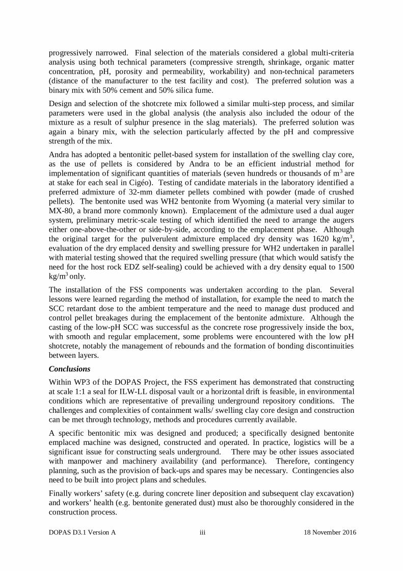
progressively narrowed. Final selection of the materials considered a global multi-criteriaanalysis using both technical parameters (compressive strength, shrinkage, organic matterconcentration, pH, porosity and permeability, workability) and non-technical parameters(distance of the manufacturer to the test facility and cost). The preferred solution was abinary mix with 50% cement and 50% silica fume.Design and selection of the shotcrete mix followed a similar multi-step process, and similarparameters were used in the global analysis (the analysis also included the odour of themixture as a result of sulphur presence in the slag materials). The preferred solution wasagain a binary mix, with the selection particularly affected by the pH and compressivestrength of the mix.
Andra has adopted a bentonitic pellet-based system for installation of the swelling clay core,as the use of pellets is considered by Andra to be an efficient industrial method forimplementation of significant quantities of materials (seven hundreds or thousands of m3 areat stake for each seal in Cigéo). Testing of candidate materials in the laboratory identified apreferred admixture of 32-mm diameter pellets combined with powder (made of crushedpellets). The bentonite used was WH2 bentonite from Wyoming (a material very similar toMX-80, a brand more commonly known). Emplacement of the admixture used a dual augersystem, preliminary metric-scale testing of which identified the need to arrange the augerseither one-above-the-other or side-by-side, according to the emplacement phase. Althoughthe original target for the pulverulent admixture emplaced dry density was 1620 kg/m3,evaluation of the dry emplaced density and swelling pressure for WH2 undertaken in parallelwith material testing showed that the required swelling pressure (that which would satisfy theneed for the host rock EDZ self-sealing) could be achieved with a dry density equal to 1500kg/m3 only.
The installation of the FSS components was undertaken according to the plan. Severallessons were learned regarding the method of installation, for example the need to match theSCC retardant dose to the ambient temperature and the need to manage dust produced andcontrol pellet breakages during the emplacement of the bentonite admixture. Although thecasting of the low-pH SCC was successful as the concrete rose progressively inside the box,with smooth and regular emplacement, some problems were encountered with the low pHshotcrete, notably the management of rebounds and the formation of bonding discontinuitiesbetween layers.
ConclusionsWithin WP3 of the DOPAS Project, the FSS experiment has demonstrated that constructingat scale 1:1 a seal for ILW-LL disposal vault or a horizontal drift is feasible, in environmentalconditions which are representative of prevailing underground repository conditions. Thechallenges and complexities of containment walls/ swelling clay core design and constructioncan be met through technology, methods and procedures currently available.
A specific bentonitic mix was designed and produced; a specifically designed bentoniteemplaced machine was designed, constructed and operated. In practice, logistics will be asignificant issue for constructing seals underground. There may be other issues associatedwith manpower and machinery availability (and performance). Therefore, contingencyplanning, such as the provision of back-ups and spares may be necessary. Contingencies alsoneed to be built into project plans and schedules.
Finally workers’ safety (e.g. during concrete liner deposition and subsequent clay excavation)and workers’ health (e.g. bentonite generated dust) must also be thoroughly considered in theconstruction process.

DOPAS D3.1 Version A iv 18 November 2016
Application of the lessons learned from the FSS experiment and feedback to referencedesigns are considered in WP4 of the DOPAS Project and reported in Deliverable D4.8 (WP4FSS Experiment Summary Report) and in D4.4. (WP4 Integrated Report). These 2 lastreports also include an analysis of further work required to develop seal designs so that theyare ready for implementation in the Cigéo repository in the near future.

DOPAS D3.1 Version A v 18 November 2016
List of DOPAS Project PartnersThe 14 partners from 8 different countries in the DOPAS Project are listed below. In theremainder of this report each partner is referred to as indicated:Posiva Posiva Oy Finland
Andra Agence nationale pour la gestion des déchets radioactifs FranceDBETEC DBE TECHNOLOGY GmbH Germany
GRSGmbH
Gesellschaft für Anlagen- und Reaktorsicherheit Germany
Nagra Die Nationale Genossenschaft für die LagerungRadioaktiver Abfälle
Switzerland
RWM Radioactive Waste Management Limited UKSÚRAO Správa Úložišť Radioaktivních Odpadu (Radioactive
Waste Repository Authority – RAWRA)Czech Republic
SKB Svensk Kärnbränslehantering AB Sweden
CTU Czech Technical University Czech RepublicNRG Nuclear Research and Consultancy Group Netherlands
GSL Galson Sciences Limited UKBTECH B+ Tech Oy Finland
VTT Teknologian Tutkimuskeskus VTT Oy (VTT TechnicalResearch Centre of Finland Ltd)
Finland
UJV Ustav Jaderneho Vyzkumu (Nuclear Research Institute) Czech Republic

DOPAS D3.1 Version A vi 18 November 2016
List of Acronyms – Abbreviations
AECL: Atomic Energy of Canada LimitedASN: Autorité de Sûreté Nucléaire (Nuclear Safety Authority in France)BMU: Bundesministerium für Umwelt, Naturschutz und Reaktorsicherheit (Federal
Ministry for the Environment, Nature Conservation, Building and NuclearSafety in Germany)
BMWi: Bundesministerium für Wirtschaft und Energie (Federal Ministry forEconomic Affairs and Energy in Germany)
Cigéo: Centre Industriel de Stockage Géologique (Industrial Geological Repository inFrance)
DOMPLU: Dome PlugDOPAS: Full-scale Demonstration of Plugs and SealsEBS: Engineered barrier systemEC: European CommissionEDZ: Excavation damaged zoneEE: Expert ElicitationELSA: Entwicklung von Schachtverschlusskonzepten (Development of shaft closure
concepts)EPSP: Experimental Pressure and Sealing PlugFSS: Full-scale Seal (test)GBT: Green Break TechnologyGPR: Ground penetrating radarHRL: Hard Rock LaboratoryILW: Intermediate-level wasteLASA: Langzeitsicherer Schachtverschluß im Salinar (Long-term Safe shaft closure
in Salt)LECA®: Light-weight expanded clay/concrete aggregateLVDT: Linear variable differential transformerOPC: Ordinary Portland ConcretePHM: Physical Hydraulic ModelPIM: Physical Interaction ModelPOPLU: Posiva PlugPVDF: Polyvinylidene fluorideR&D: Research and developmentRSC: Rock Suitability ClassificationSCC: Self-compacting concreteSTUK: The Finnish Nuclear Regulatory Authority

DOPAS D3.1 Version A vii 18 November 2016
TC-Tests: Triaxial compressions testsTDR: Time domain reflectometer
THM-Ton: Untersuchung der THM-Prozesse im Nahfeld von Endlagern inTonformationen (investigation of THM processes in the near field of arepository in clay)
TRL: Technology Readiness LevelTSO: Technical Support OrganizationURC: Underground Research CentreURCF: Underground Rock Characterisation FacilityURL: Underground research laboratoryWMO: Waste management organisationWP: Work package

DOPAS D3.1 Version A viii 18 November 2016
Table of ContentsExecutive Summary .................................................................................................................. i1. Introduction ........................................................................................................................ 1
1.1 Background ............................................................................................................... 11.2 Objective ................................................................................................................... 21.3 Scope and Link to other DOPAS Deliverables ........................................................... 31.4 Terminology and abbreviations.................................................................................. 41.5 Report Structure ........................................................................................................ 4
2. FSS Experiment .................................................................................................................. 52.1 FSS Experiment Background and Objectives ............................................................. 52.2 FSS Material Testing and Development ..................................................................... 82.3 Siting of FSS ........................................................................................................... 152.4 Construction of the FSS Test Box ............................................................................ 162.5 Installation of FSS Components ............................................................................... 192.6 Lessons Learned from the Design and Installation of FSS ........................................ 25
3. Achievements, Lessons Learned and Future Challenges ................................................ 273.1 Good Practice for Successful Experiment Planning.................................................. 273.2 Location of the Demonstrator .................................................................................. 283.3 Design of Concrete Components of Plugs and Seals ................................................ 283.4 Design of Bentonite System for the Swelling Clay Core .......................................... 293.5 Challenges during Excavation and Construction of the Experiment Site .................. 293.6 Challenges during Installation ................................................................................. 303.7 Logistics .................................................................................................................. 303.8 Health and Safety .................................................................................................... 30
4. Conclusions ....................................................................................................................... 315. References ......................................................................................................................... 32

DOPAS D3.1 Version A 1 18 November 2016
1. Introduction
1.1 Background
The Full-Scale Demonstration of Plugs and Seals (DOPAS) Project is a EuropeanCommission (EC) programme of work jointly funded by the Euratom Seventh FrameworkProgramme and European nuclear waste management organisations (WMOs). The DOPASProject is running in the period September 2012- August 2016. Fourteen European WMOsand research and consultancy institutions from eight European countries are participating inthe DOPAS Project. The Project is coordinated by Posiva (Finland). A set of full-scaleexperiments, laboratory tests, and performance assessment studies of plugs and seals forgeological repositories are being carried out in the course of the project.The DOPAS Project aims to improve the industrial feasibility of full-scale plugs and seals,the measurement of their characteristics, the control of their behaviour in repositoryconditions, and their performance with respect to safety objectives. This work does not startfrom a clean slate, since previous works (at a lower scale) were anteriorly implemented bysome of the participants. For example, the work carried out in the FP6 ESDRED project isone of the reference works on which the DOPAS work is partly building on.
The Project is being carried out in seven Work Packages (WPs). WP1 includes projectmanagement and coordination and is led by Posiva, Finland. WP2, WP3, WP4 and WP5address, respectively, the design basis, construction, compliance testing, and performanceassessment modelling of five full-scale experiments and laboratory tests. WP2, WP3, WP4and WP5 are led by SKB (Sweden), Andra (France), RWM (United Kingdom), and GRS(Germany), respectively. WP6 and WP7 address cross-cutting activities common to thewhole project through review and integration of results, and their dissemination to otherinterested organisations in Europe and beyond. WP6 and WP7 are led by Posiva.The DOPAS Project focuses on tunnel, drift, vault and shaft plugs and seals for clay,crystalline and salt rocks:
· Clay rocks: the Full-scale Seal (FSS) experiment, being undertaken by Andra in asurface facility at St Dizier, is an experiment of the construction of a drift andintermediate level waste (ILW) disposal vault seal.
· Crystalline rocks: experiments related to plugs in horizontal tunnels, including theExperimental Pressure and Sealing Plug (EPSP) experiment being undertaken bySÚRAO and the Czech Technical University (CTU) at the Josef underground researchcentre (URC) and underground laboratory in the Czech Republic, the Dome Plug(DOMPLU) experiment being undertaken by SKB and Posiva at the Äspö Hard RockLaboratory (Äspö HRL) in Sweden, and the Posiva Plug (POPLU) experiment beingundertaken by Posiva, SKB, VTT and BTECH at the ONKALO Underground RockCharacterisation Facility (URCF) in Finland, which is also the site of the futureFinnish repository.
· Salt rocks: tests related to seals in vertical shafts under the banner of the Entwicklungvon Schachtverschlusskonzepten (development of shaft closure concepts – ELSA)experiment, being undertaken by DBE TEC together with the Technical University ofFreiburg and associated partners, complemented by laboratory testing performed byGRS and co-funded by the German Federal Ministry for Economic Affairs andEnergy (BMWi).
DOPAS D3.1 Version A 2 18 November 2016
Each experiment represents a different stage of development. The Swedish experiment wasstarted prior to the start of the DOPAS Project and was pressurised during the early stages ofthe Project. The Finnish, Czech and French experiments were designed and constructedduring the Project. Initial pressurisation of the Finnish and Czech experiments occurredwithin the last year of the Project. The French experiment was not pressurised, but“investigation dismantling” of the experiment was undertaken during the Project. TheGerman tests focused on the early stages of design basis development and on demonstrationof the suitability of designs through performance assessment studies and laboratory testing,and will feed into a full-scale experiment of prototype shaft seal components to be carried outafter DOPAS.
This report is Deliverable D3.1 of the DOPAS Project and is part of WP3. The objective ofthis report is to provide an integrated summary of the work undertaken for the design andconstruction of the scale 1:1 experiment called FSS (Full Scale Seal), carried out by Andra,with the scientific support of NAGRA.
A parallel report, DOPAS Deliverable D4.4 and more specifically D4.8 in WP4, discusses theperformance of the FSS experiment and the feedback to the design basis.
This report aims to summarise the work undertaken and identify the lessons learned from thefollowing aspects of the experimental work:
· The objectives of the FSS experiment as undertaken in the DOPAS Project.
· The preliminary laboratory investigations and in situ materials testing that helped inthe determination and confirmation of the properties of the materials used in the FSSexperiment.
· The approach used to site the FSS experiment, and the reasons for selecting thelocation chosen.
· The excavation or construction of the experiment location.
· The installation of the experiment (seal) components.Lessons learned are considered from the perspective of this individual experiment and bycross-comparing the outcomes from the design and construction work undertaken.
1.2 Objective
The objective of this report is to provide an integrated summary of the work undertaken andthe lessons learned in the DOPAS Project WP3 related to the detailed design and constructionof the FSS experiment:
· The objectives of the experiments undertaken in the DOPAS Project.
· The laboratory investigations and in situ materials testing that helped in thedetermination and confirmation of the properties of the materials used in theexperiments.
· The approach used to site the full-scale experiments, and the reasons for selecting thelocation chosen.
· The excavation or construction of the experiment location.
· The installation of the experiment components.

DOPAS D3.1 Version A 3 18 November 2016
1.3 Scope and Link to other DOPAS Deliverables
The intended audiences of this report D3.1 are technical staff and technical management ofWMOs, and the report has been written primarily for this audience. The report is alsoexpected to be of potential interest to regulators and TSO (Technical support organizations).This WP3 report (D3.1) is part of a series of WP-level summary reports describing theintegrated outcomes of the technical work in DOPAS:
· D2.4, the WP2 Final Report (DOPAS, 2016a), describes the design basis for the plugsand seals considered in DOPAS, conceptual and basic designs, and the strategyadopted in programmes for demonstrating compliance with the design basis. Thedesign basis is presented for both the repository reference design and the full-scaleexperiment design.
· D3.30, the WP3 Final Summary Report (DOPAS, 2016b), summarises the workundertaken and the lessons learned from the detailed design and construction of thevarious experiments implemented in DOPAS. These include the full-scaledemonstrators, laboratory work and its upscaling, and the learning provided by thepractical experience in constructing the experiments.
· D4.4, the WP4 Integrated Report (DOPAS 2016c), summarises what has been learntwith respect to the repository reference designs for plugs and seals. The report alsoconsiders alternatives to the repository reference designs (e.g. the wedge-type pluginvestigated by Posiva). It considers what can be concluded from the full-scaleexperiments conducted in DOPAS with respect to the technical feasibility of installingthe reference designs, the performance of the reference designs with respect to thesafety functions listed in the design basis, and identifies and summarisesachievements of DOPAS WP2, WP3 and WP4 at the time of writing. D4.4 alsoconsiders the feedback from the work to the design basis.
· D4.8, the WP4 D4.8 FSS Experiment Summary Report (Bosgiraud et al., 2016),which summarises the outcomes from FSS.
· D5.10, the WP5 Final Integrated Report (DOPAS, 2016d), describes theconceptualisation of plugs and seals in post-closure safety assessments and theexpected long-term evolution of plugs and seals. This includes a description of theevidence that the materials used in plugs and seals will maintain their requiredperformance for the period specified in the design basis.
D3.1 is based on information available by the date of data freeze (on 31 December 2015). Atthis time, all design and installation work had been completed, although some assessment ofthe work was on-going. Progress in the FSS experiment by this date was as follows:
· For FSS, the upstream containment wall was cast in June 2013, the clay core wasemplaced in August 2014 and the downstream shotcrete plug was emplaced inSeptember 2014. Investigations of FSS were undertaken in the periodNovember 2014 to July 2015, followed by “investigation dismantling” betweenAugust 2015 and December 2015 (information related to this phase is dealt with inD4.4 and D4.8).
The various technical reports detailing the phases of design and construction of FSS arereferred in Chapter 5 of the present D3.1 Report.

DOPAS D3.1 Version A 4 18 November 2016
1.4 Terminology and abbreviations
Throughout this report consistent terminology has been applied. This has required, in places,changing the terminology used in a specific programme or within a specific country. The keyterms that have been changed for consistency are:
· In this report, the term used to describe the combination of materials in a specificconcrete is mix. In specific cases, this term replaces the use of formulation andrecipe.
· In this report, the term used to describe a test of plug/seal components at a reducedscale is mock-up.
In general, in the DOPAS Project it has been agreed that reference to IAEA glossary (2013)is made in the Project to use this glossary for the terms, which are not specifically describedin the report or in the list of abbreviations.
1.5 Report Structure
This report is presented in the following sections:
· Chapter 2 provides a summary of the experiences and learning from FSS. For thisexperiment, the following issues are described:
o The experiment background and objectives.o The development and testing of materials used in the experiment.
o The structural design, i.e., the work undertaken to select the components in theexperiment and their geometrical properties.
o Siting of the experiment.o Excavation of the experiment location or construction of the experiment
facility.o Construction of the experiment.
o Lessons learned regarding the design and construction of the specific sealexperiment.
· Chapter 3 provides an integrated discussion of the lessons learned and futurechallenges from the design and construction of the FSS experiment.
· Chapter 4 provides conclusions from the Report.
· Chapter 5 is the list of the main DOPAS and FSS Deliverables which are linked to thepresent D3.1 Report.

DOPAS D3.1 Version A 5 18 November 2016
2. FSS Experiment
This chapter provides a summary of the learning from design and construction of the FSSexperiment:
· In Section 2.1, the background to the experiment and its objectives are summarised.
· In Section 2.2, the phases of testing and selection of materials prior to FSS full scaleimplementation are described.
· In Section 2.3, the siting of the FSS experiment is explained.
· In Section 2.4, the construction of the FSS test box (drift model) is described.
· In Section 2.5, the installation of the FSS components is summarised, with particularfocus on the novel aspects of the experiment.
· Discussion of the lessons learned regarding the design and installation of the FSSexperiment is provided in Section 2.6.
Further outcomes of the design and construction of FSS are available in the FSS ExperimentSummary Report (D4.8 - Andra, 2016).
2.1 FSS Experiment Background and Objectives
There are potentially up to 130 seals envisaged (at this stage of design) in the Frenchreference repository (aka Cigéo) concept for HLW and ILW. Three types of seals arerecognised: (vertical) shaft seals, (inclined) ramp seals, and (horizontal) drift and ILWdisposal vault seals. Each category of seal consists of a swelling clay core positionedbetween two concrete containment walls (plugs). The swelling clay core provides therequired long-term hydraulic conductivity performance of the seal, whereas the containmentwalls are included to mechanically contain the clay core when swelling.Andra has proposed two different conceptual designs for seals (Figure 2.1):
· A Reference Solution in which the concrete drift lining in the swelling clay coresection is either totally or partially removed prior to emplacement of the core.Removal of the lining allows direct contact of the swelling clay core with the hostrock, and the sealing of any potential flow paths within the lining and along itsinterfaces with the bentonite and host rock.
· An Alternative Solution in which radial hydraulic cut-offs (also known as “grooves”)are sawn from the host rock allowing the excavation damaged zone (EDZ) to beintercepted by the bentonite material in the seal.
Reference Solution Alternative Solution
Figure 2.1: Conceptual design for seals in Andra’s Cigéo disposal concept.

DOPAS D3.1 Version A 6 18 November 2016
During the review of Andra’s Dossier 20091, the nuclear authority (ASN) asked Andra toprove the industrial feasibility of seals by constructing technological demonstrators at scale1:1.The FSS experiment was built in response to ASN’s request, to prove the technical feasibilityof constructing a seal at full scale, and especially to:
· Demonstrate the industrial feasibility of emplacement of large volumes of bentoniteand emplacement of low-pH concrete and shotcrete at the scale of a Cigéo seal(approximately ten metres in diameter and several tens of metres in length).
· Define the operational requirements useful to obtain the specified properties, forexample the tolerances on the density distribution in the core after emplacement or onthe ratio of acceptable residual voids.
· Define and deploy the control means to check the compliance, during construction,with the emplacement requirements.
· Define and deploy the control means to check the compliance, after construction, withthe emplacement requirements.
The main difference between the reference and FSS designs for the Andra drift and ILWvault seal is the length of the seal. The real seal underground will be longer than the sealconsidered in FSS. The FSS experiment investigates two types of low-pH containment wall,one using self-compacting concrete (SCC) and the other using shotcrete, to allow thepreferred method to be selected and incorporated into the seal reference concept.Technical feasibility includes demonstrating the ability of the approach used to emplace theclay core to be suitable for filling recesses in the clay host rock, i.e., any potential breakoutsgenerated during the removal of the concrete support lining. Therefore, the concrete test boxincludes recesses that mimic breakouts.As the experiment is focused on the construction and installation of the seal, the materialswere not saturated or otherwise pressurised to check the swelling pressure and hydraulicconductivity. Complementary experiments were undertaken in parallel with FSS. Theseinclude the REM experiment, which is part of WP4 of the DOPAS Project and consists of an“as close as possible to in situ conditions” resaturation test undertaken in a surface laboratorywith the same bentonite pellets/powder mixture as used in FSS (cf. Deliverable D4.2).The conceptual design of the FSS experiment is illustrated in Figure 2.2 and the schedule ofactivities is summarised in Table 2.1. Further information on the FSS experiment conceptualdesign and design basis is presented in D2.4, DOPAS (2016a).
1 The Dossier 2009 presented Andra’s operational safety case and developments to the design of the Cigéorepository since Dossier 2005 (Andra, 2005).

DOPAS D3.1 Version A 7 18 November 2016
Figure 2.2: Schematic illustration of the FSS experiment design.
Table 2.1: The schedule of activities undertaken in the FSS experiment.
Period Activity
August 2012 Beginning of studies
November 2012 – June 2013 Mock-up (box) construction
August 2012 – July 2013 Low-pH SCC concrete and shotcrete development
August 2012 – April 2014 Development of bentonite materials and methodologyto emplace the core
July 2013 Low-pH SCC containment wall construction
August 2014 Bentonite core construction
September 2014 Low-pH shotcrete containment wall construction
October 2014 – July 2015 Scientific investigations
August 2015 – December 2015 “Investigation Dismantling” followed by completedeconstruction of FSS

DOPAS D3.1 Version A 8 18 November 2016
2.2 FSS Material Testing and Development
2.2.1 Development and Testing of the SCC Mix
Studies were carried out to develop and test the mix for the low-pH SCC, first in a laboratory,then in tests at the metre and several-metre scales. Further details of the development andtesting of the low-pH SCC mix are provided in D3.4, Bosgiraud and Foin (2014).The design and selection of the concrete mix was undertaken in the following three steps:
1. Step 1: Identification of Binder Options: The first step in development andtesting of the SCC mix was testing of different binder compositions in a laboratory.Eight compositions were studied (Table 2.2) and their impact on pH, compressivestrength and curing temperature were measured (Table 2.3). After thisinvestigation, four of the eight binders were selected for further testing based ontheir potential suitability for application in FSS. The compositions selected forfurther testing were:
· B50 CEM I 52.5 Le Teil.
· T3 (L) Le Teil.
· B50 CEM III/A 42.5 Héming.
· B50 CEM III/A 52.5 Rombas.2. Step 2: Laboratory Testing of the SCC Mix Options: The four selected binders
were tested in concrete mixtures in a laboratory to determine their properties.Slump flow measurements were used to test “flowability”. Visual examinationgave valuable information on the concrete quality, based on the distribution ofaggregates, aggregate/paste separation and bleed water. Laboratory testing alsoincluded measurement of the temperature increase due to curing, the compressivestrength, the porosity, and the pH of the pore solution. After this testing, it wasdecided to omit the T3 (L) Le Teil composition from further testing.
3. Step 3: Metric-scale Testing of the SCC Mix Options: The three remainingmixtures were then tested at the metric scale in field conditions using a ready-mixplant selected for the FSS project (Figure 2.3). For this step, the concrete mixtureswere produced using industrial methods and used to fill test boxes with a volumeof 1 m3 (Figure 2.4). After 28 days, cores were extracted for analysis.
Following Step 3, a multi-criteria analysis was carried out in two phases to select the mostsuitable mix. The first phase was a technical analysis based on the measured compressivestrength, the pH value, the porosity and permeability of the samples (Table 2.4). This phasedid not allow clear identification of a preferred composition, and, therefore, an additionalphase, which included non-technical considerations, was undertaken (referred to as a globalmulti-criteria analysis). As illustrated in Figure 2.5, five criteria were included in this laststep: pH, shrinkage (referred to as “retrait” in Figure 2.5), distance of the manufacturer fromthe test facility, presence of organic matter and cost (referred to as “coût” in Figure 2.5).
Based on the global multi-criteria analysis, the B50 CEM III/A 52.5 Rombas binder wasidentified as the preferred composition for the low-pH SCC. Further testing of this mix in atest box with a volume of 12 m3 verified the industrial feasibility of using this mix, based ona consideration of its curing and hardening.

DOPAS D3.1 Version A 9 18 November 2016
Table 2.2: Binder compositions considered during Step 1.
ComponentBinary CEM I Ternary CEM I Binary CEM III
B40 B50 T1(CV) T3(L) B20 B30 B40 B50
Cement 60% 50% 37.5% 20% 80% 70% 60% 50%
Silica Fume 40% 50% 32.5% 32.5% 20% 30% 40% 50%
Fly Ashes - - 30% - - - - -
Slag - - - 47.5% - - - -
BinderSilicaContent
~53% ~61% ~56% ~54% ~42% ~50% ~57% ~64%
Table 2.3: Measured pH, compressive strength and curing temperature for the eightbinder compositions considered in Step 1, and their rank order for eachparameter - pH and compressive strength were measured after 28 days.
Binder Composition
pH CompressiveStrength
Maximumtemperature
increase
Value(slurry)
Rank
Value(MPa) Rank (°C) Rank
BinaryCEM I
B50 Le Teil 11.6 4 50.1 2 14.4 5
B40 Le Havre 11.5 3 41.9 6 10.0 3
TernaryCEM I
T3(L) Le Teil 11.8 5 42.0 5 9.5 1
T3(L) Le Havre - - 42.3 4 - -
BinaryCEM III
B40 III/A Rombas 11.9 6 51.0 1 - -
B40 III/A Héming 11.9 6 - - - -
B50 III/A Rombas 11.3 2 44.3 3 11.5 4
B50 III/A Héming 11.1 1 39.0 7 9.7 2

DOPAS D3.1 Version A 10 18 November 2016
(a) Concrete mixer-truck used to carry concrete © Paul Calin (b) Sample for testing
Figure 2.3: Delivery of concrete for metric-scale testing of concrete mixtures (D3.4,Bosgiraud and Foin, 2014).
Figure 2.4: Test box used for metric-scale testing. In this photograph, the fluidity of theconcrete is shown at the outlet of the pump and evidence of self-compaction isprovided by the smooth surface produced (no vibration or shocks were appliedduring the test) (D3.8, Bosgiraud and Foin, 2014).

DOPAS D3.1 Version A 11 18 November 2016
Table 2.4: Measured compressive strength, pH, porosity and permeability for the 3mixtures tested at the metric-scale.
Metric Test BlocksComposition
Compressive Strength(MPa) pH Porosity Permeability
m2
Cylinder Cores
28 d 90 d 28 d 28 d 90 d 28 d 28 d
B50 CEM III/A52.5 Rombas 37.8 50.7 34.9 11.8 10.1 19.7% 17.10-18
B50 CEM III/A42.5 Héming 36.9 49.6 31.3 11,8 10.2 19.,9% 19.10-18
B50 CEM I52.5 Le Teil 46.7 61.9 46.2 12,2 10.3 17.7% -
B50 CEM III/A 52.5 Rombas B50 CEM III/A 42.5 Héming B50 CEM I 52.5 Le Teil
Distance
Org.
CoûtRetrait
pH
Distance
Org.
CoûtRetrait
pH
Distance
Org.
CoûtRetrait
pH
Overall score : 4/5 Overall score: 2.8/5 Overall score: 2/5
Figure 2.5: Global multi-criteria analysis to identify the preferred option for the low-pHSCC to be used in FSS. The French terms are defined in the text (Bosgiraudand Foin, 2014).
2.2.2 Development and Testing of the Shotcrete Mix
The research to identify the preferred low-pH shotcrete mix for construction of thedownstream containment wall used a similar approach to the research used to identify thepreferred option for the low-pH SCC. Three candidate mixes were selected for testing:
· B50 CEM III/A 52.5 Rombas.· B50 CEM I 52.5 Le Teil.· B50 CEM III/A 52.5 Héming.
After test spraying of metric-scale test panels (Figure 2.6), cores were extracted to measurethe same properties as measured for SCC, i.e., compressive strength, pH, porosity andshrinkage (Table 2.5). In addition, the quantity of material experiencing rebound duringemplacement was estimated by collection and measurement of material in front of the testpanels (Table 2.5).
Organic
Organic
Organic

DOPAS D3.1 Version A 12 18 November 2016
B50 CEM III/A 52.5 Rombas(100 % silica fume)
B50 CEM I 52.5 Le Teil(50% + silica fume + 50%
nanosilica)
B50 CEM III/A 52.5 Héming(100 % silica fume)
Figure 2.6: Photographs of the outcomes from the test spraying of metric test panels.
Table 2.5: Technical results for the three shotcrete mixtures tested at the metric-scale.
Parameter B50 CEM III/A52.5 Rombas
B50 CEM I52.5 Le Teil
B50 CEM III/A52.5 Héming
Slump (mm)
t0 200 200 200
t0+1h 220 200 210
t0+2h 180 90 180
Percentage of rebound 2.2 % 8.0 % 9.1 %
Compressive strength at 28 days (MPa) 11±3 24±3 19±3
pH after 28 days 11.3 11.4 12.3
Water porosity after 28 days 21.1% 22.3% 19.8%
Shrinkage after28 days (μm/m)
Endogenous 19 12 19
Total 420 280 500
As for the selection of the low-pH SCC, final selection of the low-pH shotcrete was based ona global analysis (Figure 2.7). In addition to the parameters considered in the low-pH SCCanalysis, the global analysis for selection of the preferred low-pH shotcrete mix alsoconsidered the odour of the mixture resulting from sulphur present in the slag materials(“odeur” in Figure 2.7) and the compressive strength at 28 days (“résistance” in Figure 2.7).The preferred mixture based on this multi-criterial analysis was identified as being the recipeB50 CEM I 52.5 Le Teil, and this mixture was subsequently taken forward for shotcreting ofthe downstream containment wall.

DOPAS D3.1 Version A 13 18 November 2016
B50 CEM III/A 52.5 Rombas B50 CEM I 52.5 Le Teil B50 CEM III/A 52.5 Héming
Retrait
pH
Distance
CoûtRésistance
Odeur
Organ.
Retrait
pH
Distance
CoûtRésistance
Odeur
Organ.
Retrait
pH
Distance
CoûtRésistance
Odeur
Organ.
Overall score: 1.9/5 Overall score: 3.5/5 Overall score: 1.9/5
Figure 2.7: Global multi-criteria analysis to identify the preferred option for the low-pHshotcrete to be used in FSS. The French terms are defined in the text.
Further details of the development and testing of the low-pH shotcrete mix are provided inthe report D3.9, Andra (2016) and references therein.2.2.3 Selection of Bentonite Materials
The selection of the bentonite materials for the swelling clay core was undertaken in thefollowing steps:
· First, a decision was made to adopt a pellet-based admixture rather than use ofpre-compacted bentonite blocks. This is motivated by Andra’s belief that the use ofpre-compacted blocks (bricks) is not a choice technically commensurate with the needfor emplacing very large volumes of swelling clay in Cigéo in an industrial way.
· Second, laboratory testing of bentonite pellet and powder mixtures was undertaken inparallel with manufacturing tests to identify the appropriate pellet and powdermixture, and initial water content.
· Third, mock-up testing and desk-based design work was used to test and develop thedesign of the bentonite emplacement method.
Adoption of a Pellet-based SystemAndra selected a pellet-based system instead of pre-compacted bentonite blocks because thissolution is considered by Andra to be a more efficient industrial method of implementationfor significant quantities of material. The method is similar to that proposed by Nagra foremplacement of bentonite buffer materials (Kohler et al., 2015). In the case of FSS (and thelarge seals envisaged by Andra for the Cigéo repository), the pellets can be filled by conveyorsystems while the blocks are to be positioned by human action or robots at a much loweremplacement speed. Furthermore, the erection of a wall of blocks raises the issue of itsstability, since the blocks are not assembled with a mortar.
Laboratory Testing and Manufacturing Trials of Pellet and Powder SystemAndra specified the use of a pure sodium bentonite, without any other constraints, for theswelling clay core. The contractor chose WH2 bentonite from Wyoming. The raw WH2material is equivalent to the well-known MX-80, but is provided by a different supplier.
Several studies were carried out to determine the required properties of the bentonite claycore material to be used in FSS. The initial requirements on the swelling clay materialsfocused on the swelling pressure and hydraulic conductivity; these are 7 MPa and

DOPAS D3.1 Version A 14 18 November 2016
1x10-11 m/s, respectively. During material testing, the dry density value of 1620 kg/m3,corresponding to a swelling pressure of 7 MPa after hydration, was specified to ensure thatthe required swelling pressure could be achieved.Laboratory studies were carried out to determine the preferred pellet size and choice ofpowder. The objective was to obtain the best possible dry density for the emplaced pellet-powder admixture. The tests showed that the best value for the dry density was obtainedusing an admixture with the following properties:
· The pellets had a cylindrical-spherical form with dimensions of: 32 mm (height) and32 mm (diameter), and weight of around 42 g. This size was selected as acompromise between the optimum void between the pellets (to allow for a goodemplacement of the powder) and the manufacturing capacity of the pellet producingmachine (diameter vs compacting pressure).
· The 32 mm pellets were manufactured with a material composed of 90% WH2powder and 10% WH2 fine particles with a grain size <160 μm. The dry density ofthe manufactured pellets was ≥2040 kg/m3. The water content of bentonite wasadjusted to around 4.5% (between 4% and 5%). This water content was the bestcompromise to obtain a good density of pellets.
· The bulk dry density of the pellets measured in the laboratory is approximately1.10 kg/m3, while the bulk dry density of standard WH2 powder is 1060 kg/m3.Based on geometrical considerations, an optimum density value was observed for a70% pellet and 30% powder mixture ratio. An addition of 30% of powder to thepellets can provide only an additional 320 kg/m3 of dry density to the admixture.Therefore, the use of 32-mm pellets and WH2 powder does not provide the drydensity of 1620 kg/m3 required. To achieve the required density, the pellets weremixed with crushed pellets rather than with powder. The ratio of pellets to crushedpellets was 70%-30%. Laboratory measurement of this admixture confirmed that itsbulk density was 1620 kg/m3, i.e., the bulk density of the admixture in the laboratorymatched the initial specification.
· The powder made with crushed pellets was controlled by sieving of the material toensure a maximum grain size of 4 mm. This maximum was imposed to ensure thatthe powder could fill the voids between the pellets; powder with a grain size >4 mmcould stay on the top of the heap (creating a bridging effect) preventing the powderfrom accessing the inter-pellets voids.
Mock-up Testing and Emplacement Machine DesignIn parallel with the laboratory studies, a mock-up metric-scale setup was developed fortesting the selected bentonite admixtures and the backfilling device. This device is based ontwo augers for emplacement of pellets and powder (Figure 2.8).
The metric emplacement tests demonstrated that the auger devices are the best adapted meanscapable of backfilling the drifts in an industrial way. However, the obtained bentonitedensity was less than the specified value of 1620 kg/m3 which was obtained in laboratory.The best values of the obtained density in this mock-up test were 1510 kg/m3 with the powderauger above the pellets auger and 1470 kg/m3 with the two augers side by side. The mainreason for these lower values was deemed to be the breakage of some pellets during thehandling process resulting in closure of inter-pellet spaces and preventing the powder fromaccessing some voids. As a result, mechanical resistance tests were introduced to measurethe “hardness” of the pellets (resistance to erosion or breakage due to a compacting effort as

DOPAS D3.1 Version A 15 18 November 2016
envisaged inside the screw conveyor pipe) at the production workshop and at the FSS sitebefore emplacement.
Figure 2.8: Mock-up tests at the metric scale of the bentonite pellet-powder admixtureemplacement using augers.
Evaluation of the relationship between dry density and swelling pressure for WH2 undertakenin parallel with the design work described above showed that with a dry density of 1.5 kg/m3
the swelling pressure would be around 5 MPa. This pressure was finally considered byAndra to be sufficient, and the FSS specifications were modified so that the required averagedry density in the clay core would be 1500 kg/m3 instead of 1620 kg/m3 specified originally.Further details of the selection of bentonite materials are provided in the report D3.12, Andra(2016) and references therein.
2.3 Siting of FSS
The FSS experiment was carried out in a warehouse at a surface facility in Saint-Dizier,which is close to the French underground research laboratory (URL) at Bure. The choice of asurface facility was made for the following reasons (D3.2, Bosgiraud and Foin, 2013):
· Carrying out the experiment underground requires a large excavation, with asignificant duration, and a considerable amount of equipment and materials to bemobilised and emplaced. The Bure URL is essentially a qualification facility, inwhich the logistical flexibility to undertake large experiments such as FSS is limited.Logistical limitations include, for example, the means to transport significantquantities of materials, the number of people permitted underground at any one time,and the geometry of the underground tunnels, which limit the ability to use largeequipment. A surface facility does not have these logistical limitations, and, inaddition, allows investigations of the experiment from the external surfaces of the“test box”.
· Several experiments were already planned to be carried out at Bure at the same timeas the period in which FSS was to be conducted; this also limited the ability to useBure for FSS.
· The experimental costs, schedule and requirements on later “investigationdismantling” also favoured the use of a surface facility.
The Saint-Dizier site was proposed by the Contractor in charge of the FSS experiment(GME), and accepted by Andra, for three reasons: the vicinity of Bure (30 km) where many

DOPAS D3.1 Version A 16 18 November 2016
Andra staff are located, the height of the warehouse (more than 10 m of free gap under theroof frame), and the proposed building was suitable from the perspective of controlling theair humidity and temperature, as it had a double-insulated roof and atmosphere controlequipment available.
2.4 Construction of the FSS Test Box
The FSS “test box” (or drift model) design concept was specified by Andra to contain theFSS experiment. Report D3.2 (Bosgiraud and Foin, 2013) provides a detailed description ofthe test box construction. The test box is made of Ordinary Portland Concrete (OPC) and isshown in Figure 2.9. One of the main requirements on the test box is for it to remain stableduring the various construction and filling operations. Displacements and deformations mustnot exceed 5 mm and must be monitored throughout the whole duration of the FSS test (D3.2,Bosgiraud and Foin, 2013). The results of preliminary geotechnical investigations on the soilof the warehouse concluded that there was a need for replacing the alluvium layer presentunderneath the facility floor with a substrate (a limestone aggregate) between -2 m and -4 mto reinforce the soil beneath the test box. The construction procedure of the test box issummarised below and is described in more detail in D3.10 (Bosgiraud and Foin,2013).
Figure 2.9: 3D schematic of the FSS test box (D3.2, Bosgiraud and Foin, 2013).The first step in construction of the test box was to pour a concrete foundation slab on thenewly created limestone aggregate platform (Figure 2.10a). Construction of the lower part ofthe concrete box framework commenced in December 2012 and was completed in nineweeks. The box structure was then built with seven lower blocks and seven upper blocks(each 5-m long). A wooden formwork was used to make the circular inner form, while forthe outside a classic steel formwork was used (Figure 2.10b).The concrete lining recesses were shaped by adding wood rings onto the principal innerformwork, and a special folio was pasted onto the rings to simulate the texture of the argillitewalls in the breakout zones (Figure 2.10c).

DOPAS D3.1 Version A 17 18 November 2016
After completion of the lower part of the text box, a layer of sand was laid on the groundinside the box in order to enable working on a flat floor and three steel sheets were used toslide the scaffolding equipment from a given block casting position to the next one(Figure 2.10d).

DOPAS D3.1 Version A 18 18 November 2016
a) View of the concrete foundation b) The inner wooden form and steelform
c) the folio pasted on the wood circularinner form to simulate the argillitewalls
d) The completed lower part of the testbox with a sand layer at the bottomand scaffolding also shown
e) Removal and translation of thewooden formwork between the twophases of the upper block casting
f) The completed test box
Figure 2.10: Different stages in the construction of the FSS test box (D3.10, Bosgiraud andFoin, 2013).

DOPAS D3.1 Version A 19 18 November 2016
After that, the inner wooden framework was turned upside down and deposited on a shoringsystem made of a support beam and brackets so that the construction of the upper part of thebox could be performed. Two phases of casting were carried out to complete the upper partof the box. Between the two phases of concrete casting, the external framework was totallyremoved, while the internal framework was slipped on rollers (Figure 2.10e).It took thirteen weeks to construct the upper part of the box (Figure 2.10f), with constructioncompleted in May 2013. A set of stairs was used to access the top of the test box. Twelveobservation windows were installed to enable observation and checking of the bentonitefilling operations. A local “mine-like” exhaust ventilation system was also installed, with aclosing door in the front of the box, in order to control the ambient temperature(18°C < q < 30°C) and humidity (50% < HR < 75%) inside the box, as required by theexperiment specification.
The test box construction was successfully commissioned as “test ready” by mid-June 2013,paving the way for the first step in the seal construction, i.e., installation of the upstreamlow-pH SCC containment wall.
2.5 Installation of FSS Components
Installation of FSS started with the construction of the first concrete containment wall(Section 2.5.1) followed by bentonite clay core emplacement in parallel with a support wall(Section 2.5.2). The last installed component of FSS was the second containment wall madeof shotcrete (Section 2.5.3). The installation of the measurement system was undertaken inparallel with installation of the other components and is described in Section 2.5.4. Theinstallation of the components is described in detail in the report D3.12 (Andra, 2016).2.5.1 First Containment Wall
The casting operations for the first concrete containment wall took place in July 2013. Thelow-pH SCC casting operations were carried out with two main objectives (D3.8, Bosgiraudet al., 2014):
· To realise a monolith type containment wall (with a volume of ~250 m3),
· To minimise (as much as possible) the concrete shrinkage and cracking extent.
To achieve these 2 objectives, it was decided to pour concrete in batches of 7 m3 at a time,i.e., the maximum capacity of the truck. In order to simulate the expected logisticalconstraints in a repository, for the majority of the SCC containment wall a period of twohours elapsed between starting one casting operation and starting the next. This period isconsistent with the expected time for transport of concrete from the surface to undergroundemplacement sites in the Cigéo project. However, for the upper part of the wall, one batchper hour was poured to avoid rinsing the concrete pump pipes between two mixer-trucks andto maintain a sufficiently fluid concrete mass in the upper part of the wall to improvebonding.
The fabrication of the low-pH concrete batches took place in the concrete mixer plant inSaint-Dizier (some 5 km from the FSS site); the same plant was used for the preliminary testphases. The concrete was transported by mixer trucks. Each mixer truck batch represented alayer about 15-20 cm thick in the containment wall construction progress. Each pour wascompleted in approximately twenty minutes followed by a pause for approximately one hourand forty minutes before commencement of the next pour. All of the mixer truck 7 m3
batches passed two qualifying slump flow tests, one just after mixing (i.e. at plant site) and

DOPAS D3.1 Version A 20 18 November 2016
another immediately before emplacement (i.e. at FSS construction site). The slump flowtarget was 550-750 mm.
The temperature of the concrete and the ambient temperature significantly affected therheology of the fresh SCC. Therefore, during emplacement of the low-pH SCC containmentwall, it was decided to adjust the retarding agent with respect to the ambient temperature; thehigher the ambient temperature, the higher the retarding agent dosage. The superplasticiserdosage was kept unchanged. Moreover, it was required that the maximal temperature reached inthe concrete during curing should be less than 50°C. Thus, the heat emitted during curing wasmeasured during trials and later used to estimate the maximum temperature at which the concretecould be poured to meet the requirement. It was found that the maximum temperature increaseduring curing and hardening was 24°C. In practice, it was then decided not to pour concrete withan ambient temperature greater than 26°C. Those ambient conditions were effectively respectedat the time of casting operations.
The casting operations were judged to be successful as the low-pH concrete roseprogressively inside the box, with smooth and regular emplacement (Figure 2.11). To finishthe operation, it was necessary to totally close the formwork before the concrete was injectedin the upper part of the containment wall (Figure 2.11).
Figure 2.11: Pouring and even emplacement of SCC inside the test box (left) andemplacement of SCC close to the recess (right) (D3.8, Bosgiraud et al., 2014).
After casting, the SCC containment wall was left for preliminary curing for about one week,and then the formwork was stripped from the concrete with no particular difficulties. Some28 days of hardening later, the injection of low-pH slurry (grout) commenced in order tobond the containment wall to the test box concrete liner. The grout was emplaced throughsmall pipes installed at the higher part of the cast concrete (two for grouting and two others toserve as air evacuation). The mix for the grout is provided in Table 2.6 and the groutingmachine is shown in Figure 2.12. The quantity of injected slurry turned out to be very small(a few tens litres). It was thus inferred that, in FSS, there was only a small gap generated byconcrete shrinkage and/or that the bonding had already taken place. This issue wasinvestigated further during the dismantling of FSS, which is reported in D4.4 (DOPAS,2016c) and D4.8 (Bosgiraud et al, 2016).

DOPAS D3.1 Version A 21 18 November 2016
Table 2.6: The mix for the low-pH grout used for bonding in FSS.
Component Quantity (kg/m3)
CEM III/A 52.5 Rombas 311.7
Silica fume 311.7
Very fine sand (“Sablon”) 781.7
Water 438.0
Glenium ®Sky 537 1.9% of (C + SF) : 11.4 L
Rhéomac ®SRA 872 2.0% of (C + SF) : 12.5 L
Figure 2.12: Grouting machine used for bonding in the FSS experiment.

DOPAS D3.1 Version A 22 18 November 2016
2.5.2 Bentonite Clay Core and Support Wall
The swelling clay core backfilling activities were commenced in October 2013 (aftercompletion of the SCC containment wall).
Before the start of bentonite emplacement, all material was delivered and stored at thewarehouse, including 847 tonnes of 32-mm diameter pellets (in 770 octabins) and368.5 tonnes of crushed pellets powder (in 335 big bags). A specially developed“backfilling” machine for the purpose of bentonite emplacement was constructed(Figure 2.13). The machine comprises a carriage that moves in the y-direction into the testbox on two rails overlaid by a movable turret in the x-direction. This turret incorporates allcomponents used for conveying of materials: a hopper for pellets, a hopper for crushedpellets, and a crane used to move the augers in the z-direction as bentonite emplacementprogresses.
Figure 2.13: The bentonite mix emplacement machine.The filling procedure commenced with emptying of the octabins (containing bentonitepellets) and the big bags (containing bentonite powder) into separate movable hoppers(Figure 2.14). The movable hoppers were then lifted by forklift trucks and emptied into fixedhoppers positioned on the filling machine (Figure 2.15). Filling of the lower two thirds of theclay core volume was completed with the two augers (one for the pellets and one for thepowder) one above the other to reproduce the laboratory experiments in which the best resultswere obtained (Figure 2.16). Filling of the upper third was completed with the augers side-by-side to enable the filling of the recesses (reproducing the metric tests).The process of transferring bentonite powder into hoppers and then to the forklift trucksfollowed by placement in the concrete test box generated high-levels of dust. Examination ofthe ventilation system after the first day of use identified non-ideal performance of the mine-type filter, which was then cleaned, resulting in lower levels of dust in the warehouse facility.

DOPAS D3.1 Version A 23 18 November 2016
Figure 2.14: Emptying of an octabin containing bentonite pellets (left) and a big bag withbentonite powder (right) into hoppers.
Figure 2.15: Transferring the bentonite into the filling machine using forklift trucks (left)and then transfer of pellets through a conveyor belt into the auger (right).
Figure 2.16: Bentonite materials transferred through the augers (left) into the core of theseal (right).

DOPAS D3.1 Version A 24 18 November 2016
Emplacement of the bentonite materials was facilitated by construction of supporting walls.At first, a supporting wall was partially constructed (at mid-height) to contain the first part ofthe bentonite core. The supporting wall was then progressively constructed concurrently withthe bentonite filling operations. This wall was built with half-cubic-meter low-pH concreteblocks made with the same SCC as that used for the first containment wall. The swellingclay core emplacement was finished in August 2014.
During the filling operations, two problems were encountered and mitigated:
· Too many pellets were found to be broken during the emplacement process, whichwould have a significant impact on the emplaced density. The augers were inspectedand excessive wear of the transport screw was discovered. Subsequently, the screwwas replaced, resulting in far less breakages.
· The gear motor of the bentonite powder auger also required replacement.2.5.3 Second Containment Wall
The second low-pH shotcrete containment wall was constructed after emplacement of amortar to close the joints in the supporting wall that would separate the swelling clay corefrom the shotcrete wall. The mortar was emplaced between blocks and at the contact with thetest box wall. This containment wall was built by spraying shotcrete in wet conditions inorder to test an alternative to the use of low-pH SCC. The low-pH shotcrete containmentwall (Figure 2.17) was finished in September 2014 after solving initial challenges withfabrication of the shotcrete:
· The rheology of shotcrete was initially found to be highly variable; some batches ofshotcrete were found to be too stiff and some too soft. This difficulty was solved byincreasing the time of mixing from 30 seconds to two minutes so as to have a betterincorporation of silicate fume. After making three batches (with a volume of 3 m3), acheck was then carried out to adjust the amount of additives for the last four batchesto get the expected final consistency.
· The rebound was around 10 to 12% and the difficulty was to thoroughly remove itafter each mixer-truck emplacement to prevent its incorporation into the wall.
Figure 2.17: Installing the second containment wall made of low pH shotcrete in FSS.

DOPAS D3.1 Version A 25 18 November 2016
2.5.4 System for Measuring FSS Components Parameters
The main environmental condition parameters measured in the FSS experiment to ensure thatthey are similar to those expected in Cigéo included, ambient temperature (measuredcontinuously), humidity (measured continuously), and dust in the air (measured randomly asdone in a mine). For the concrete and shotcrete containment walls, continuous measurementsof the curing temperature and shrinkage were implemented. For the bentonite core, thequality of the material used at each step of fabrication and the quality of the filling and massbalance of the admixture were checked. 3D scans were performed for evaluation of thebentonite backfilled volumes at pre-defined phases. The emplaced bentonite dry density wasalso evaluated. More information on the measurement system is available in Andra (ReportD4.8, Bosgiraud et al. 2016). It is important to mention that the monitoring of FSS wasdedicated only for the test run-time of the experiment until its dismantling.
2.6 Lessons Learned from the Design and Installation of FSS
Prior to the commissioning of the FSS experiment, some of the lessons learned concern theneed to allow enough time to design the experiment, especially with no previous experienceof full-scale tests of plugs and seals. All the experiment specifications need to beindividually checked and cross checked to ensure consistency (for example, the temperatureand pH values for concrete, type of materials for the bentonite and their density, etc.).
An important lesson for the material specifications is the selection of realistic and achievabletargets. This was the case with the bentonite material dry density specification. Initially ahigh value of the dry density was specified even though a more realistic and lower target wasfound to be sufficient and more easily achievable. Where feasible, a range of values formaterial specifications should be provided rather than absolute values as this will facilitatequality control during installation. It furthermore provides “robustness” to the concept.
Besides, for the WH2 admixture, the original target swelling pressure of 7 MPa turned out tobe somehow a real “overkill” and was reduced to 5 MPa since this value is compatible withthe seal permeability target and the argillites EDZ self-sealing.
For instance, the requirement for the concrete temperature (50°C) was not a requirementgiven in D2.4, but a decision made by Andra for the input for design and work specificationsgiven to the contractor. The explanation about this is that Andra thought it right to have asafety margin (i.e. 10°C less than the usual 60°C temperature requirement commonly foundfor curing of concretes). On the other side, for the low-pH SCC, it was found that thetemperature at the experiment site impacts on concrete, therefore, this will need to beappropriately managed underground. For the shotcrete, it was concluded that new metric orplurimetric tests would need to be implemented in order to have a better know how of theshotcrete emplacement methods.
Selection of both the SCC and shotcrete mixes used both “technical” (e.g., pH, shrinkage,compressive strength and presence of organic matter) and “non-technical” considerations(e.g. distance from manufacturer and cost). Overall, the shotcrete mixes tested had a lowerstrength than the SCC mixes.
Similarly, the concrete pH value requirements were changed from the original pH 10.5-11@28 days to pH 10.5-11 @90 days. The justification is that the original requirement wassome type of “overkill”, since pH value keeps diminishing with time for these types ofconcrete.

DOPAS D3.1 Version A 26 18 November 2016
Development of the bentonite admixture recognised the need to combine pellets with crushedpellets rather than the standard WH2 powder (the crushed pellets are referred to as “powder”)to achieve higher densities, and the need to arrange augers vertically rather than horizontallyto achieve the best density. However, emplacing the bentonite near the tunnel ceilingrequires the augers to be arranged horizontally.
During experiment installation, one of the main challenges was dealing with the vast amountof dust generated by handling bentonite in the warehouse. The use of a scraper conveyor totransfer material into the filling machine instead of forklift trucks would reduce the dustgenerated during unloading of bentonitic components (powder in particular) into the forklifttruck hoppers and also reduce the transfer time of material. A special hooded vacuum tubewith a filter to remove dust could be incorporated into the design of the bentoniteemplacement machine.During construction of the experiment, it was emphasised that the safety and health of staff isparamount, especially with material which can potentially be hazardous (e.g., silica fume,bentonite dust, etc.). Supervisors need to be mobilised all the time during the full-scale testin order to verify that the procedures and regulations are always adhered to.

DOPAS D3.1 Version A 27 18 November 2016
3. Achievements, Lessons Learned and Future Challenges
This chapter provides an integrated discussion of the achievements of, and the lessons learnedfrom FSS, in relation to the design and construction of full-scale experiments for plugs andseals, and for full-scale experiments in general. Achievements and lessons learned from FSSProject experiments are discussed in seven sections:
· Section 3.1 discusses good practice for successful planning of a full-scale experiment.
· Section 3.2 discusses the strengths and weaknesses of the location used for conductingthe full-scale experiment in Saint-Dizier.
· Section 3.3 discusses the achievements and lessons learned with respect to design andinstallation of the FSS seal low pH concrete containment walls.
· Section 3.4 discusses the achievements and lessons learned with respect to design andinstallation of bentonite mix forming the FSS swelling clay core.
· Section 3.5 discusses the achievements and lessons learned with respect to excavationof the future seal emplacements in Cigéo.
· Section 3.6 presents some of the challenges encountered during installation of FSSand how these were overcome.
· Section 3.7 summarises logistical issues encountered during the design andconstruction of FSS.
· Section 3.8 summarises health and safety issues addressed during the design andconstruction of FSS.
Evaluation of the monitoring and measurement systems used in the DOPAS Projectexperiments, including their installation, is included in WP4 of the DOPAS Project andreported in Deliverables D4.4 (DOPAS 2016c) and D4.8 (Bosgiraud et al., 2016).
3.1 Good Practice for Successful Experiment Planning
The design and construction of the FSS experiment have been successful, within thetimeframe of the DOPAS Project. Success of the design and construction activities has beenunderpinned, in part, through the use of good planning, through application of systematicdesign processes, by taking a stepwise approach involving studies at multiple scales, andthrough a mix of experienced and less-experienced staff.
The FSS experiment had benefitted from the development of comprehensive and detaileddesign bases, as recorded in the DOPAS Design Basis report D2.1 (White et al., 2014). Thisexperiment had clear objectives, which allowed the Andra team to have a clear and sharedvision of how activities related to the global objective:
· The FSS experiment was built to prove the technical feasibility of constructing a sealat full scale,
· It was not saturated or otherwise pressurised to check the swelling pressure andhydraulic conductivity since these processes were examined and implemented in theparallel experiment REM which is part of WP4 of the DOPAS Project (cf. DeliverableD4.2, Report on Bentonite Saturation Test, Conil et al., 2015).

DOPAS D3.1 Version A 28 18 November 2016
This full-scale experiment was supported by a series of mock-ups undertaken at a range ofscales to support the upscaling of the design from the laboratory to the full scale. Forexample, Andra rearranged the transfer system used to emplace the bentonite pellet andpowder mix based on metric-scale testing of the backfilling machine. Mock-up tests may berequired by the regulator prior to implementation of a process within an operating repository;the experience from the DOPAS Project (and from FSS) has illustrated the general benefitfrom undertaking such activities.Another successful aspect of the organisation of the experiment was the incorporation ofexperienced staff within the project (including from the Contractor’s side) even if somedelays were experienced.
The FSS experiment also benefitted from cooperation between staff from Andra and Nagra,the latter one having just completed the FE Experiment, within the frame of the ECfinancially supported LUCOEX Project. These included lessons related to bentonite mixdesign and bentonite mix emplacement methods.
3.2 Location of the Demonstrator
At the time of FSS planning, working underground was naturally first considered. The firstprospect was the Andra Bure URL, which turned out to be incompatible with the experimentlogistical needs and the “full scale” geometrical requirements, while the URL workload wasanother factor for discarding such a choice. An ordinary underground facility (i.e. out of theargillite formation) was also quickly considered and discarded for legal (unadapted tunnelregulations) and environmental (difficulties to reproduce Cigéo-like conditions) reasons.
Thus, locating the FSS experiment at the surface provided the benefit of flexible access to thetest box for both monitoring of the construction and for the ultimate dismantling activities.The additional space in the building meant that it was feasible to store materials and ensuretheir availability for the filling operations. Although the experiment was not undertakenunderground (in Cigéo like conditions), it was feasible to control the ambient temperature andrelative humidity so that the conditions were suitably representative.
Note: It is worth mentioning that the fact of not working underground is partly misleading, asfar as the drift liner dismantling issues (and clay rock purging) are not dealt with in thisexperiment, by contrast with other experiments like DOMPLU and POPLU. However, theseissues will addressed during the Cigéo Pilot Phase (2025-2034), when “full scaledemonstrators” will be built in a ramp and in a drift.
3.3 Design of Concrete Components of Plugs and Seals
A range of low-pH concrete mixes have been developed, tested in FSS. Shotcrete and SCCformulations have been selected and used to build the large concrete monoliths (250m3 each)forming the containment walls on each side of the swelling clay core. Laboratory testing ofthese mixtures has demonstrated that they have the required curing temperature, hydraulicconductivity, shrinkage characteristics, strength, water interaction (pH of pore water orleachate) and rheology/segregation characteristics for application in repository plugs andseals.
All of the low-pH concrete mixes used in the DOPAS Project (and in FSS) used a commonapproach to provision of the low pH. This included the substitution of cement commonlyused in high-pH concretes with silica fume and fly ash, with the addition of filler.Aggregates were locally sourced. All of the cement mixes needed to be accounted for the

DOPAS D3.1 Version A 29 18 November 2016
properties of the specific components, such as locally-sourced cements and aggregates, andhad to be tailored to the boundary conditions of the experiment.
Amongst the key properties of concrete used in plugs and seals are the values forcompressive strength, pH of leachate and maximum curing temperature. High compressivestrengths of ~40-60 MPa could be achieved for some of the concrete mixes tested in FSS.Note: By contrast with the Czech EPSP experiment, Andra decided not to include glass orsteel fibres for additional strength, since the phenomenology (corrosion, ageing or chemicalinteraction) of this type of material is difficult to predict over a significant lapse of time(thousands of years).Challenges encountered during the emplacement of the concrete mixes have been overcome:
· In FSS, the preparation of concrete mixes at the concrete plant had to be scrutinisedand monitored to ensure compliance with the mix specification, for example to checkthe homogeneity of the dry material mixture.
· However, there is further work to be undertaken on low-pH concrete mixes.Additional work should be done to evaluate the sensitivity of the concreteperformances to marginal variations in component percentages and infer, by so doing,how robust a given mix can be. The role of certain additives e.g., plasticisers shouldalso be further explored to see how dependant on the ratio between organic andmineral components a concrete mix composition can be. This is necessary to betterassess the robustness of the safety demonstration (i.e. determine the role ofcomplexing organic products in long-term safety). All of the concrete mixes used inFSS are novel materials, and, therefore, are not yet compliant with existing standards.
· Therefore qualification of the concrete mixes is required, and this is discussed furtherin Deliverables WP4.4 and D4.8 of the DOPAS Project.
3.4 Design of Bentonite System for the Swelling Clay Core
In FSS, a mixed pellet and crushed pellet bentonite system was used to erect the swelling claycore, which has an internal diameter of 7.6 m. Although the original bentonite dry emplaceddensity requirement was 1620 kg/m3, evaluation of the “dry density linked” swelling pressurefor the bentonite undertaken in parallel with material testing showed that the requiredswelling pressure could be achieved with a dry emplaced density of 1500 kg/m3 only.One of FSS swelling clay core challenges was to manage the heterogeneity in the system,particularly the vertical heterogeneity, which results in a lower density being achievedtowards the top of the bentonite layers, i.e. close to the drift roof. In principal, this isachieved by exceeding the design specification in the lower parts of the layer to compensatefor lower densities in the upper parts of the layer. In FSS, the overall dry emplaced density ofthe system meets the design specification. Furthermore, at smaller scales, it was many timesobserved that homogenisation of the saturated material appears with time.
3.5 Challenges during Excavation and Construction of the Experiment Site
As noted above, in FSS, rock excavation was not carried out as the experiment was located ina surface facility. Partial dismantling of the drift concrete liner in Cigéo will be an issue ofits own, for which scale 1:2 tests are planned by Andra in its Bure URL in the years to come.

DOPAS D3.1 Version A 30 18 November 2016
These tests will provide further information on the potential for break-outs in drift and ILWvault seal locations, and provide a basis for excavation methodology development. This mayinclude further work to develop criteria related to the EDZ at the location of plugs and seals.
3.6 Challenges during Installation
Installation of the FSS experiment was successfully completed within the timeframe of theDOPAS Project. However, there have been challenges associated with installation ofmaterials close to the model drift wall (especially the roof) and with installation of theinstrumentation. This was found to be an issue in several DOPAS experiments:
· All of the experiments required modified procedures for emplacement of materialclose to the roof space. Future design improvements should include better processesfor installation of materials in this area.
· FSS was conducted in a surface facility, obviating the need for certain activities, suchas removal of the tunnel lining before installation of the swelling clay core.Procedures for removal of the tunnel lining will need to be developed in the future.
In FSS, the main challenge was the pellet breakage which appeared with the progressivewearing of the augers (screws) installed inside the bentonite pellets conveyor pipes: thisbreakage contributed to a poor effective dry density of the emplaced material (a phenomenondue to the bridging effect created by the broken parts of the pellets preventing the bentonitepowder from fillings the voids). This situation led to a change of screw steel characteristicsto minimize the wearing effects.
Nonetheless, the FSS experiment demonstrated good application of quality control andconstruction procedures during the installation of the experiment components.
3.7 Logistics
Although all of the experiments were successfully installed within the course of the DOPASProject, logistical problems were faced by all experiments. Of particular note were delaysassociated with machine availability. Delays were encountered, for example, whenexcavation machines required regular maintenance. Delays in one aspect of installation canhave knock-on effects, especially when novel machinery is scheduled to be used elsewhere.Delays were experienced by the FSS experiment when the screw augers required replacementparts (an electric motor was also replaced), and, during later stages of the project,replacement screws and electric motors were made available.
Logistical issues slowed the construction process down for FSS. Besides, the manufacturer ofthe FSS bentonite mixture backfilling machine was bankrupted during the project and thiscaused an additional delay in the experiment construction start-up.In addition, FSS relied on a specialized contractor to mix concrete, which was appropriate,but delivery was challenging.
3.8 Health and Safety
The experience of the DOPAS Project has shown how health and safety concerns can slowand/or require changes to the installation of experiments. This applies to FSS, sincemanagement of dust was an issue. All workers had to wear face masks and the content ofdust in the air had to be monitored to follow the workers’ exposure. This was caused, in part,because the mining ventilation installed turned out to be insufficient.
DOPAS D3.1 Version A 31 18 November 2016
4. Conclusions
Within WP3 of the DOPAS Project, four full-scale experiments of plugs and seals have beendesigned and constructed. These include the FSS experiment in France.
Design and construction of the FSS experiment contribute to the technology readiness level(TRL5, according to Expert judgement, cf. D6.3.2 – Palmu 2016) of seal installation in Cigéoin the future. The completion of the experiment design and construction represents asuccessful collaboration between Andra and its contractors or consultants.
The design and construction of FSS has demonstrated that seals are more challenging andcomplex sub-systems of the repository than previously recognised. However it is worthknowing that the challenges and complexities of seal design and construction can be metthrough available technology, methods and procedures currently available.
Significant work on low-pH concrete, contact grouting and bentonite pellet systems has beenundertaken within FSS.
Logistics is a significant issue for concrete containment walls and swelling clay cores. Theremay be multiple components requiring installation and appropriate time must be allowed forthese materials to be installed and evolve prior to installation of the next component. Theremay be issues associated with manpower and machinery availability (and performance).Therefore, contingency planning, such as the provision of back-ups and spares may benecessary. Contingencies also need to be built into project plans and schedules at time ofrepository operations.
Application of the lessons learned from the FSS experiment and feedback to reference Cigéoseal design are considered in WP4 of the DOPAS Project and reported in Deliverables D4.4and D4.8. This includes an analysis of further work required to develop Cigéo seal design sothat it is ready (TRL9) for implementation in Cigéo in the future.

DOPAS D3.1 Version A 32 18 November 2016
5. References
· Andra (2013) - The Cigéo Project – “Meuse/Haute-Marne Reversible GeologicalDisposal Facility for Radioactive Waste” - Project Owner File Public Debate of 15May to 15 October 2013.
· White et al. (2014) - DOPAS Work Package 2 - Deliverable D2.1 (“Design Bases andCriteria”).
· DOPAS (2016a) - WP2 Final Report: Design Basis for DOPAS Plugs and Seals.DOPAS Work Package 2, Deliverable D2.4, Version 1.
· Bosgiraud et al. (2013) - DOPAS Work Package 3, Deliverable D3.2 (“FSS tunnelmodel design report”).
· Bosgiraud et al. (2016) - DOPAS Work Package 3, Deliverable D3.3 (“Report onclayish material definition for FSS”) – combined with D3.7.
· Bosgiraud et al. (2016) - DOPAS Work Package 3, Deliverable D3.4 (“Report on lowpH concrete formulas for FSS”) – combined with D3.8.
· Bosgiraud et al. (2016) - DOPAS Work Package 3, Deliverable D3.5 (“Lab testReport on the performance of the clayish material for FSS”) – combined with D3.7.
· Bosgiraud et al. (2016) - DOPAS Work Package 3, Deliverable D3.6 (“Lab testReport on the performance of low pH concrete for FSS”) – combined with D3.8.
· Bosgiraud et al. (2016) - DOPAS Work Package 3, Deliverable D3.7 (“Test report onFSS metric core emplacement, with clayish materials definition for FSS andLaboratory work on the performance of clayish materials for FSS”).
· Bosgiraud et al. (2013) - DOPAS Work Package 3, Deliverable D3.8 (“Test report onFSS cast in box concrete with low pH concrete formulas for FSS and Laboratorywork on the performance of low pH concrete for FSS”).
· Bosgiraud et al. (2016) - DOPAS Work Package 3, Deliverable D3.9 (“Test report onFSS test panel for shotcrete”).
· Bosgiraud et al. (2013) - DOPAS Work Package 3, Deliverable D3.10 (“FSS Driftmodel construction report”).
· Bosgiraud et al. (2014) - DOPAS Work Package 3, Deliverable D3.11 (“FSS castconcrete plug construction report”).
· Bosgiraud et al. (2016) - DOPAS Work Package 3, Deliverable D3.12 (“Report onconstruction of FSS swelling clay core”).
· Bosgiraud et al. (2016) - DOPAS Work Package 3, Deliverable D3.13 (“Report onshotcrete plug construction”).
· DOPAS (2016b) - DOPAS Work Package 3 - Deliverable D3.30 (“WP3 FinalSummary Report: Summary of, and Lessons Learned from, Design and Constructionof the DOPAS Experiments”).
· Noiret et al. (2016) - DOPAS Work Package 4, Deliverable D4.1 (“Report onQualification of Commissioning Means”).

DOPAS D3.1 Version A 33 18 November 2016
· Conil et al. (2015) - DOPAS Work Package 4, Deliverable D4.2 (“Report onBentonite Saturation Test (REM)”).
· DOPAS (2016c) - DOPAS Work Package 4 Deliverable D4.4. WP4 IntegratedReport. Summary of Progress on Design, Construction and Monitoring of Plugs andSeals.
· Bosgiraud et al. (2016) - DOPAS Work Package 4, Deliverable D4.8 (“FSSExperiment Summary Report”).
· DOPAS (2016d). DOPAS Work Package 5, Deliverable D5.10. WP5 FinalIntegrated Report. DOPAS Project Deliverable D5.10.
· Palmu (2016) - Consensus memorandum for D4.4 Expert Elicitation. DOPAS WorkPackage 6, Deliverable D6.3.2. DOPAS Project Deliverable D6.3.2
· DOPAS (2016e) - DOPAS Final Project Summary Report. DOPAS Work Package 6,Deliverable D6.4. DOPAS Project Deliverable D6.4.