Doosan HF Controls - TP901-201-03-NP, ERD921 DMR TSAP ...
28
1 of 28 HF Controls DMR Control System DMR TSAP Validation Test Procedure TP901-201-03 Rev B Effective Date 5/17/2010 Author Ivan Chow Reviewer Charles McKinney Approval Ed Herchenrader Copyright © 2010 HF Controls Corporation
Transcript of Doosan HF Controls - TP901-201-03-NP, ERD921 DMR TSAP ...

1 of 28
HF Controls
DMR Control System
DMR TSAP Validation Test Procedure
TP901-201-03 Rev B
Effective Date 5/17/2010
Author Ivan Chow Reviewer Charles McKinney Approval Ed Herchenrader
HF Controls Proprietary
Copyright© 2010 HF Controls Corporation

DMR TSAP Validation Test Procedure
TP901-201-03 2 of 28 Rev. B
Revision History Date Revision Author Changes
4/30/10 A I. Chow Initial Revision 5/14/10 B I. Chow Changes to address CR2010-0108
Table of Contents
Section Title Page
1.0 PURPOSE AND SCOPE .................................................................................4
2.0 REFERENCES ................................................................................................4 2.1 Industry Standards ............................................................................................ 4
2.2 HFC Documentation ......................................................................................... 5
2.3 HFC Internal Standards and Procedures ........................................................... 5
2.4 Special Terms, Abbreviations, and Acronyms ................................................. 5
3.0 PREREQUISITES ...........................................................................................5 3.1 Equipment Required ......................................................................................... 6
3.2 Environmental Conditions ................................................................................ 6
3.3 Test Personnel ................................................................................................... 6
3.4 Precautions ........................................................................................................ 6
3.5 Red-Line Policy ................................................................................................ 6
3.6 Test Setup Requirements .................................................................................. 7
4.0 TEST SEQUENCE ..........................................................................................8 4.1 Source Code Verification .................................................................................. 8
4.2 TSAP Operability/Prudency Support Logic ..................................................... 9
4.2.1 Accuracy Tests .................................................................................................. 9
4.2.2 Response Time Test Algorithms ..................................................................... 11
4.2.2.1 Digital Response Time Algorithm Verification .............................................. 11
4.2.2.2 Analog System Response Time Algorithm Verification ................................ 13
4.2.3 Timer Test Algorithm Verification ................................................................. 15
4.2.4 Failure to Complete Scan Test ........................................................................ 16
4.2.5 Miscellaneous Functions ................................................................................. 17
4.2.5.1 Loop Counter .................................................................................................. 17
4.2.5.2 DI Operability Test Point ................................................................................ 17
4.2.5.3 DO Operability Test Point .............................................................................. 17
4.2.5.4 Analog PID Loop ............................................................................................ 18

DMR TSAP Validation Test Procedure
TP901-201-03 3 of 28 Rev. B
4.2.6 Burst of Events Test Validation ...................................................................... 19
4.3 Simulated MFT Functional Test ..................................................................... 21
4.3.1 Reset First-Out Memory Control .................................................................... 21
4.3.2 Gas Trip Valve Control Logic ........................................................................ 24
4.3.3 Burner Gas Valve Control Logic .................................................................... 24
4.3.4 Miscellaneous Logic ....................................................................................... 24
5.0 ACCEPTANCE CRITERIA .........................................................................25
6.0 QA RECORDS ...............................................................................................26
7.0 ATTACHEMENTS .......................................................................................26 Attachment 7.1 – Test Equipment Log ............................................................................. 27 Attachment 7.2 – Test Summary Record .......................................................................... 28
List of Figures Number Title Page Figure 1 Test Waveform for Automated Analog Channel Accuracy Test ........................ 9 Figure 2 General Arrangement of Digital Response Time Logic .................................... 12 Figure 3 General Arrangement for Analog Response Time Algorithm .......................... 13 Figure 4. General Arrangement of Timer Test Algorithm ............................................... 15
List of Tables Number Title Page Table 1 TSAP and HPAT Support for Analog Accuracy Testing ..................................... 9 Table 2 TSAP and HPAT Support for Digital Response Time Testing .......................... 11 Table 3 HPAT and TSAP Support for Analog Response Time Testing .......................... 13 Table 4. TSAP and HPAT Support for Timer Testing .................................................... 15 Table 5. Miscellaneous Point Assignments ..................................................................... 18 Table 6. Burst of Events Test Validation ......................................................................... 20 Table 7. TSAP Acceptance Criteria ................................................................................. 25

DMR TSAP Validation Test Procedure
TP901-201-03 4 of 28 Rev. B
1.0 PURPOSE AND SCOPE The DMR has been assembled from components of the HFC-6000 product line configured as a triple-redundant safety control system (Test Specimen). A synthetic application program (TSAP) has been configured for the redundant controller system to support functional and qualification stress testing of the system. This procedure covers validation of the program code and functional operation of this TSAP as follows: Source Code Verification – The source code file generated by the HFC One-Step
utility will be examined line by line and compared with the graphic representation of logic diagrams 700907-01 and 700908-01.
Operability Test Support - This test will verify functional operation of the TSAP
code designed to support Operability testing and verify that the test design will produce the expected data. The automated Operability tests will be started/stopped from the MCRT and controlled by algorithms within the TSAP. Execution of this test will exclude extensive recording or logging of test results, which will be accomplished during execution of the Operability tests.
Prudency Test Support - This test will verify functional operation of the TSAP code
designed to support the automated Prudency tests. The automated Prudency tests will be started/stopped from the MCRT and controlled by algorithms within the TSAP. Execution of this test will exclude extensive recording or logging of test results, which will be accomplished during execution of the Prudency tests.
MFT Logic Test – This test will verify functional operation of the Master Fuel Trip
Logic included in the TSAP. Functional testing of the TSAP code will be conducted after TP901-201-02, DMR Integration Test Plan is completed. 2.0 REFERENCES
2.1 INDUSTRY STANDARDS This test procedure constitutes part of the prequalification testing for the HFC-6000 control system. These tests have been developed to document the baseline performance of the control system Test Specimen prior to the start of qualification stress testing. EPRI TR 107330 Generic Requirements Specification for Qualifying a Commer-
cially Available PLC for Safety-Related Applications in Nuclear Power Plants, 1996

DMR TSAP Validation Test Procedure
TP901-201-03 5 of 28 Rev. B
2.2 HFC DOCUMENTATION 705005-04 DMR Remote 4 Logic Diagram, Rev. A
RS901-201-01 DMR TSAP Requirements Specification, Rev. A
DS901-201-01 TUV DMR TSAP Design Description, Rev. A
TP901-300-00 ERD921/ERD111 Master Test Plan, Rev. B
TP901-201-02 DMR Integration Test Plan, Rev. A
TP901-201-04 DMR Operability Test, Rev. A
TP901-201-05 DMR Prudency Test, Rev. A
VV901-301-02 Master Configuration List, Rev. A
2.3 HFC INTERNAL STANDARDS AND PROCEDURES QPP 5.1 Review and Approval of Documents
QPP 11.1 Test Control
WI-ENG-003 Configuration Management
WI-ENG-815 Red Line Procedure
2.4 SPECIAL TERMS, ABBREVIATIONS, AND ACRONYMS DMR Dual Modular Redundant
EWS Engineering Workstation (HFC PC software utility)
HIFR Host Interface Remote
HPAT HFC Plant Automated Tester
MCRT Microsoft/Windows CRT (HFC PC software utility)
LED Light Emitting Diode
PC Personal Computer
RTD Resistance Thermal Detector
TC Thermocouple
Test Specimen A specific combination of hardware and software components to be subjected to specified test conditions
TSAP Test Specimen Application Program
3.0 PREREQUISITES The following paragraphs define the equipment, setup, and configuration requirements for conducting the TSAP Validation Tests.

DMR TSAP Validation Test Procedure
TP901-201-03 6 of 28 Rev. B
3.1 EQUIPMENT REQUIRED This test will be conducted after successful completion of TP901-202-02 during the acceptance phase of pre-qualification testing. Minimum equipment requirements for running this test are as follows: Fully integrated DMR Test Specimen as validated by TP901-201-02 Fluke 743B Calibrator with thermocouple and RTD simulator or equivalent Record all test equipment used during this test in attachment 7.1.
3.2 ENVIRONMENTAL CONDITIONS The TSAP validation test will be conducted in the HFC testing facility without any external stress applied. The normal ambient environment in this facility is as follows:
Temperature 50° to 104° F Relative Humidity 7% to 90% noncondensing
3.3 TEST PERSONNEL All of the testing functions covered by this document will be conducted by a qualified HFC test engineer or technician at the HFC facility. 3.4 PRECAUTIONS
WARNING
Certain I/O circuits are energized with high voltages and may carry potentially hazardous current loads. Exercise caution whenever working around exposed terminals or circuitry.
3.5 RED-LINE POLICY The HFC policy for entering red-line corrections into a test procedure are presented in paragraph 2.6.2 of VV901-300-01, Master Test Plan for ERD111/ERD921. Such entries may be used to correct errors of content and procedural sequence in test documents or in engineering drawings to prevent disruption of a test in progress.

DMR TSAP Validation Test Procedure
TP901-201-03 7 of 28 Rev. B
3.6 TEST SETUP REQUIREMENTS 1. Verify that the copy of the TSAP Validation Test Procedure in hand is a controlled
copy of the latest revision according to Document Control records. 2. Verify that equipment setup is complete. 3. Verify that execution of TP901-201-02 is complete. 4. Verify the following:
a. Verify that the HPAT, PC, and Test Specimen are all powered up. b. At the PC workstation, start the Equation Editor program.
c. Open the equation file for Remote 4 (main Test Specimen controller). Verify that
the Equation Editor opens the local file without indicating any discrepancy. (This indicates that the file in the controller matches the equation file in the PC memory.) Verify that the compilation date and CRC matches the record in the MCL.
Test setup is complete: ___________________________________________ Test Engineer/Date
DMR TSAP Validation Test Procedure
TP901-201-03 8 of 28 Rev. B
4.0 TEST SEQUENCE The overall validation test will be accomplished in two stages: source code verification, and system functional test. During source code verification, the content of the source code text files will be validated against the logic diagrams from which they were created. During the functional test, the application code will be installed on the controller, and functional operation of the Operability tests, Prudency Burst of Events test, and simulated MFT logic will be verified.
4.1 SOURCE CODE VERIFICATION 1. Obtain a printout of the latest revision of the TSAP logic diagrams,
705005-04. _______
2. To ensure that the source code listings are identical to those in the Test specimen, print a copy of the TSAP equations source code files from the EWS workstation. _______
3. Verify the following items for each logic symbol represented on the TSAP logic diagram: The point type and point number in the source code printout matches
the logic symbol in the diagram. The symbol in the logic diagram matches the function (AND, OR,
NOT timer, memory, block, etc.) represented in the source code. Each timer preset represented on the logic matches the preset
statement in the source code. Each timeon/timeoff/pulse timer on the logic diagram is correctly
translated into program source code. _______
4. Trace each connection line represented on the logic diagram from source node to input node, and verify that the link is accurately represented in the source code. _______
5. Verify that each configured output channel (DO/AO) is controlled by a corresponding statement in the source code. _______
6. For analog logic, verify internal block structure as follows: a. At the EWS, open the Equation Editor. b. Open the equation file for the TSAP being evaluated. c. Locate the BL point in question. d. Open the block edit window. e. Verify that each configuration parameter shown in the logic diagram
is present in the block structure. f. Verify that the input source in the block structure matches the input
source shown in the logic diagram. g. Repeat steps d through f for each BL point included in the TSAP
code. _______

DMR TSAP Validation Test Procedure
TP901-201-03 9 of 28 Rev. B
4.2 TSAP OPERABILITY/PRUDENCY SUPPORT LOGIC The TSAP includes program code for simulated MFT logic as well as code needed to support the Operability and Prudency tests. The support logic for the Operability and Prudency tests has been designed to establish a performance baseline during the pre-qualification phase of tests for comparison with performance during and after qualification testing. The following tests are intended to verify that both the test algorithms operate as intended.
4.2.1 Accuracy Tests The algorithm for the accuracy test will permit automated testing of 4- to 20-mA AO and 0- to 5-v AI channels of the Test Specimen. The TSAP includes a test algorithm that generates a dynamic test waveform. This algorithm drives one AO channel, and the resulting signal is connected back to one AI channel. Accuracy tests for thermocouple and RTD AI channels are not automated, but the TSAP does include AIC blocks for selected input points from these modules. The functional test will consist of enabling/disabling operation of the accuracy test algorithm and verifying that the test signal drives the expected AO/AI channels. Table 1 lists the specific DMR channels in the accuracy tests; Figure 1 illustrates the test waveform to be used for the automated test, and Table 1 lists the I/O support reserved for analog accuracy tests.
ELAPSED TIME (sec)
AM
PLIT
UD
E (
%)
0
30
50
90100
00 20 40 60 80 100 120 140
70
10
Figure 1 Test Waveform for Automated Analog Channel Accuracy Test
Table 1 TSAP and HPAT Support for Analog Accuracy Testing
Signal Source Output Point Input Point Description TSAP Test Algorithm 4,AO,1 4,AI,5 10% to 90% step waveform 100Ω RTD Wire 4,AI,17 Ambient Cabinet Temp. Calibrator 4,AI,18 Manual Accuracy Testing 14.832 mV 4.AI,25 Constant Voltage Source Calibrator 4,AI,26 Manual Accuracy Testing Type E TC 4,AI,32 Ambient Cabinet Temp

DMR TSAP Validation Test Procedure
TP901-201-03 10 of 28 Rev. B
1. Verify that the Test Cabinet, Test Specimen, and PC workstation are all
power up and operating. _______ 2. Verify that card edge LEDs for all circuit cards indicate normal
completion of initialization. Verify that the card edge LEDs for each I/O card show the following:
TX and RX LEDs flash to indicate activity. DMT or STATUS LED remains on constantly _______
3. Open the Equation Editor program on the EWS, and display the TSAP for
Remote 4. _______ 4. Display 4,BL,56 (the ANO block controlling 4,AO,1). _______ 5. Use the MCRT to start the Analog Accuracy test. _______
6. Display block values, and verify that the test signal generators in the TSAP begin generating the test waveform (Figure 1).
_______
7. Use the Equation Editor to verify signal activity as indicated in Table 1.
_______
8. Display 4,BL,51 (the AIC block processing the input from 4,AI,5).
Verify that the block exhibits each step of the accuracy algorithm. _______ 9. Use the MCRT to stop the Accuracy test. _______ 10. Verify that the test waveform stops dynamic operation and returns to its
minimum value. (Once the algorithm has started, it will continue running until the current cycle is completed.) _______
_____________________________________ Test Engineer, Date

DMR TSAP Validation Test Procedure
TP901-201-03 11 of 28 Rev. B
4.2.2 Response Time Test Algorithms The TSAP includes separate trigger and response algorithms to support measurement of the response time for analog and for digital processing functions. Operation of both test algorithms can be started and stopped separately from the MCRT workstation.
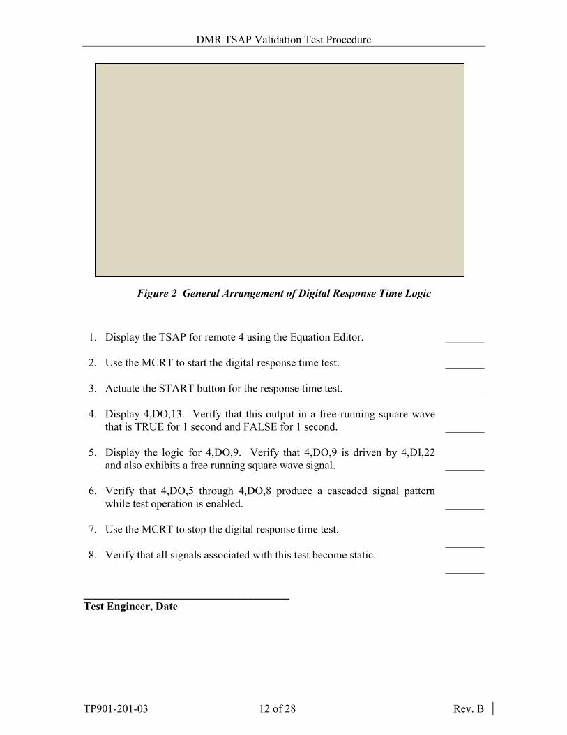
4.2.2.1 Digital Response Time Algorithm Verification The TSAP provides a round-robin discrete input/output/input/output program pattern composed of four DI channels and four DO channels. The first DI channel controls the first DO channel, and that signal is physically connected to the next DI channel in sequence. The last DO signal is then fed back to the first DI channel, and a NAND gate in the link from the first DI to the first DO permits the test engineer to start or stop the test from the MCRT workstation. The TSAP also produces a free-running square wave to drive a test trigger signal (4,DO,13) that controls the input to 4,DI,22, which serves as the input for a simulated trip memory. When the test is disabled, the memory image of all four DI/DO points in the cascaded sequence will have a stable TRUE state, and the trip memory will remain static. When the test is first enabled, 4,DO,5 will become FALSE, and this state will propagate through the cascaded chain with each successive processing cycle. Once this state is fed back to 4,DI,27, each point will become TRUE in sequence, producing a square wave pattern that is TRUE for four processing cycles and FALSE for four processing cycles. The simulated trip memory location will become TRUE on the FALSE-to-TRUE transition of 4,DI,22, and it will be reset FALSE when 4,DI,22 returns to a FALSE state. Table 2 lists significant I/O points associated with this test, and Figure 2 illustrates the arrangement of the logic algorithm.
Table 2 TSAP and HPAT Support for Digital Response Time Testing
Signal Source Output Point Input Point Description TSAP internal logic 4,DO,8 4,DI,27 Cascaded DI/DO sequence
Test Trigger 4,DO,13 4,DI,22 Free-running 0.5-Hz square wave test signal
TSAP internal logic 4,DO,9 Simulated Trip Output
DMR TSAP Validation Test Procedure
TP901-201-03 12 of 28 Rev. B
S
R
FLDI,27
DI,28
DI,29
DI,30
DO,5
DO,6
DO,7
DO,8
DO,9
TO DI,1
DI,22TRIGGER IN TRIP OUTPUT
Response Time
Trigger
DO,13 TRIGGER OUTFL
TSAP
Figure 2 General Arrangement of Digital Response Time Logic
1. Display the TSAP for remote 4 using the Equation Editor. _______ 2. Use the MCRT to start the digital response time test. _______ 3. Actuate the START button for the response time test. _______ 4. Display 4,DO,13. Verify that this output in a free-running square wave
that is TRUE for 1 second and FALSE for 1 second. _______ 5. Display the logic for 4,DO,9. Verify that 4,DO,9 is driven by 4,DI,22
and also exhibits a free running square wave signal. _______ 6. Verify that 4,DO,5 through 4,DO,8 produce a cascaded signal pattern
while test operation is enabled. _______ 7. Use the MCRT to stop the digital response time test. _______ 8. Verify that all signals associated with this test become static. _______
_____________________________________ Test Engineer, Date
DMR TSAP Validation Test Procedure
TP901-201-03 13 of 28 Rev. B
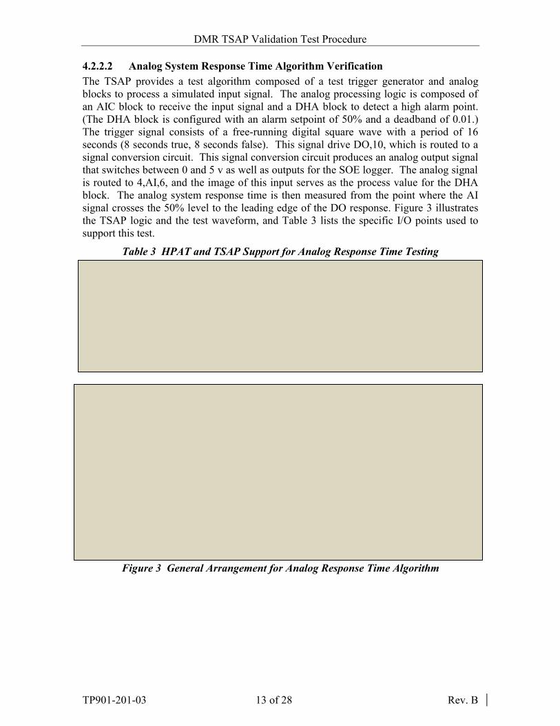
4.2.2.2 Analog System Response Time Algorithm Verification The TSAP provides a test algorithm composed of a test trigger generator and analog blocks to process a simulated input signal. The analog processing logic is composed of an AIC block to receive the input signal and a DHA block to detect a high alarm point. (The DHA block is configured with an alarm setpoint of 50% and a deadband of 0.01.) The trigger signal consists of a free-running digital square wave with a period of 16 seconds (8 seconds true, 8 seconds false). This signal drive DO,10, which is routed to a signal conversion circuit. This signal conversion circuit produces an analog output signal that switches between 0 and 5 v as well as outputs for the SOE logger. The analog signal is routed to 4,AI,6, and the image of this input serves as the process value for the DHA block. The analog system response time is then measured from the point where the AI signal crosses the 50% level to the leading edge of the DO response. Figure 3 illustrates the TSAP logic and the test waveform, and Table 3 lists the specific I/O points used to support this test.
Table 3 HPAT and TSAP Support for Analog Response Time Testing
Signal Source Output Point Input Point Description Test Trigger 4,DO,2 Signal converter Free-running square wave
with a period of 16 sec. Test Trigger Signal
converter 4,AI,6 Free-running analog square
wave signal Analog output 4,AO,2 4,AI,6 Output image of the analog
test trigger TSAP internal logic 4,DO,10 Simulated trip output
20
40
30
80
70
60
50
100
90
10
Alarm SPResponse Time
Trip SignalS
R
AI,6
AIC
DHASP = 50%
DB = 0.01%
TSAP
Response Time
Trigger
DO,20FL
SignalConverter
DO,10
ANO AO,2
SOE Figure 3 General Arrangement for Analog Response Time Algorithm

DMR TSAP Validation Test Procedure
TP901-201-03 14 of 28 Rev. B
1. Display the TSAP equation file for Remote 4 using Equation Editor. _______ 2. Use the MCRT to start the analog response time test. _______ 3. Display the control logic for 4,DO,20. Verify that the algorithm switches
with a period of 8 sec. _______ 4. Display the logic controlling 4,AO,2. Verify that both 4,AI,6 and 4,AO,2
show activity. _______ 5. Display the logic controlling 4,DO,2. Verify that both 4,DO,10 switches
in response to the image of 4,AI,6. _______ 6. Use the MCRT to stop the analog response time test. _______ 7. Verify that all I/O points associated with this test become static when the
test is not running. _______ _____________________________________ Test Engineer, Date
DMR TSAP Validation Test Procedure
TP901-201-03 15 of 28 Rev. B
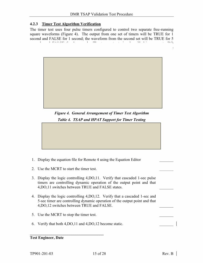
4.2.3 Timer Test Algorithm Verification The timer test uses four pulse timers configured to control two separate free-running square waveforms (Figure 4). The output from one set of timers will be TRUE for 1 second and FALSE for 1 second; the waveform from the second set will be TRUE for 5 seconds and FALSE for 1 second. The two output signals will drive separate DO channels so that the timer periods can be logged by separate SOE input channels. The specific channels reserved for the timer test are listed in Table 4.
TSAP
GT
LT
1 SECTI
1 SEC GT
TILT
FL
1 SECTI
5 SECGT
LTTI
GT
LT
DO
DO
Figure 4. General Arrangement of Timer Test Algorithm
Table 4. TSAP and HPAT Support for Timer Testing
Signal Source Output Point Description TSAP Algorithm
4,DO,11 Timer Test signal No. 1 (1 sec TRUE, 1 sec FALSE)
TSAP Algorithm
4,DO,12 Timer test signal No. 2 (5 sec TRUE, 1 sec FALSE)
1. Display the equation file for Remote 4 using the Equation Editor _______ 2. Use the MCRT to start the timer test. _______ 3. Display the logic controlling 4,DO,11. Verify that cascaded 1-sec pulse
timers are controlling dynamic operation of the output point and that 4,DO,11 switches between TRUE and FALSE states. _______
4. Display the logic controlling 4,DO,12. Verify that a cascaded 1-sec and
5-sec timer are controlling dynamic operation of the output point and that 4,DO,12 switches between TRUE and FALSE. _______
5. Use the MCRT to stop the timer test. _______ 6. Verify that both 4,DO,11 and 4,DO,12 become static. _______
_____________________________________ Test Engineer, Date

DMR TSAP Validation Test Procedure
TP901-201-03 16 of 28 Rev. B
4.2.4 Failure to Complete Scan Test The TSAP includes an algorithm that introduces an infinite loop into the application code on command from the MCRT. The algorithm includes two DO points. One point serves as the trigger signal to activate the simulated fault. The second is a DO point that transitions from TRUE to FALSE on failure of the controller. In addition, the controller software sets FL,1097 whenever the Equation Interpreter fails to complete at least one pass through the entire equation file during a single context switch interval.
1. Use the MCRT to start the Failure to Complete Scan test. _______ 2. Verify that 4,DO,16 turns ON then OFF. _______ 3. Use the MCRT to disable the Failure to Complete Scan test (if still
running). _______ _____________________________________ Test Engineer, Date

DMR TSAP Validation Test Procedure
TP901-201-03 17 of 28 Rev. B
4.2.5 Miscellaneous Functions 4.2.5.1 Loop Counter The TSAP includes a loop counter 4,CO,50 that increments once during each processing cycle of the equation interpreter throughout normal operation. The value of this counter can be logged in order to obtain a direct measure for the number of equation processing cycles completed between any two points in time. 1. Open the Memory Editor. _______ 2. Read the current point value for 4,CO,50 in integer mode. Record the
counter value and the time when the value was read from the time of day display on the memory editor.
Counter Value _______________ Time of Day _____________ _______ 3. Wait a few minutes and then repeat step 2. Counter Value _______________ Time of Day _____________ _______ 4. The difference in counter values provides the number of equation cycles
completed between successive reads. _______ 4.2.5.2 DI Operability Test Point 4,DI,21 has been reserved for execution of the DI operability test. Functional verification for this point consists ensuring that TRUE/FALSE transitions can be detected from the workstation. 1. Use the memory editor to display the status of 4,DI,19. _______ 2. Supply a 24V signal to TB3-1 to TB3-3 of B1-L4-C6 to simulate a TRUE
input signal. Verify that the memory editor indicates TRUE status for this point. _______
3. Remove the signal. Verify that the memory editor indicates FALSE
status. _______ 4.2.5.3 DO Operability Test Point 4,DO,15 has been reserved for execution of the DO operability test. Functional verification for this point consists of controlling the status of the point image and verifying that the hardware channel responds. 1. Use the MCRT to control ON/OFF status of 4,DO,15 (DO Operability
Test target). _______

DMR TSAP Validation Test Procedure
TP901-201-03 18 of 28 Rev. B
2. Start the test via the DO Operability Test target. Verify that hardware DO
channel is on. (Output is at B1-R5-C8 PT11 and wired to HPAT 2,DI,399.) _______
3. Stop the test via the DO Operability Test target. Verify that the hardware
DO channel goes off. _______ 4.2.5.4 Analog PID Loop The TSAP includes a simulated closed PID loop composed of one closed loop signal, two PID controllers, and two static analog values. Table 5 lists the major elements of this simulated loop. The purpose of this loop is to establish a stable balanced state at mid range. The stability of the circuit will be monitored during the qualification stress tests to determine if the stress conditions cause the circuit to become unstable.
Table 5. Miscellaneous Point Assignments
Signal Source Output Point Input Point Description MCRT target
4,AO,5 4,AI,9 Static analog value 1 4,AO,6 4,AI,10 Static analog value 2
PID logic 4,AO,3 4,AI,7 PID loop PID logic 4,AO,4 4,AI,8 PID loop MCRT 4,BL,27 Setpoint value MCRT 4,MS,148 Three-element control
1. Configure the MCRT to control the values of 4,AO,5 and 4,AO,6. Verify 4,BL,27 setpoint value and is set to 61.9% in the logic.. _______ 2. Configure the MCRT to control the logic state of 4,MS,148. _______ 3. Reset 4,MS,148 FALSE to select single element control. _______ 4. Adjust tuning parameters of PID block 4,BL,28 and LLG block 4,BL,42
to balance the output and input values of the loop at mid range. Record the final combination of tuning parameters used. LLG block 4,BL,42: Gain ______ Lead Time________ Lag Time________ PID block 4,BL,28: Gain_______ TAUI________ TAUD __________ _______
5. Set 4,AO,5 to 75%. Verify that 4,AI,9 matches the set value. _______
DMR TSAP Validation Test Procedure
TP901-201-03 19 of 28 Rev. B
6. Set 4,AO,6 to 50%. Verify that 4,AI,13 matches the set value. _______ 7. Set 4,MS,148 TRUE to select three element control. _______ 8. Adjust tuning parameters of PID blocks 4,BL,30 and 4,BL,33 to balance
the output and input values of the loop at mid range. PID block 4,BL,30: Gain_______ TAUI________ TAUD __________ PID block 4,BL,33: Gain_______ TAUI________ TAUD __________ _______
_____________________________________ Test Engineer, Date

DMR TSAP Validation Test Procedure
TP901-201-03 20 of 28 Rev. B
4.2.6 Burst of Events Test Validation The Burst of Events test is intended to activate a significant number of I/O points simultaneously. In the case of the DMR, the limitation of available output points limits the number of total channels that can be included. Table 6 lists all I/O channels included in the test. In both cases, the TSAP contains an algorithm that drives the output channels, and each output signal is connected back to an input channel.
Table 6. Burst of Events Test Validation
BOE Signal Output Point Input Point Digital BOE 4,DO,17 4,DI,25 Digital /BOE 4,DO,18 4,DI,26 Pass-through signal from 4,DI,25 4,DO,19 Analog BOE 4,AO,7 4,AI,11 Analog /BOE 4,AO,8 4,AI,12
1. Display the equation file for Remote 4 on the EWS. _______ 2. Use the MCRT to start the BOE test. _______ 3. Display the logic controlling 4,DO,17 and 4,DO,18. Verify the
following: 4,DO,17 is controlled by cascaded 1-sec timers and continuously
switches between TRUE and FALSE while the test is running. _______ 4. Verify that 4,DI,25 is continuously switching between TRUE and
FALSE. _______ 5. Display the logic controlling 4,AO,7. Verify that the ANO block value
switches between 10% and 90%. Verify that the waveform of 4,AO,8 is the reverse of that of 4,AO,7. _______
6. Display the AIC block processing 4,AI,11. Verify that the block value
switches between 10% and 90%. _______ 7. Display the AIC block for 4,AI,12. Verify that this block exhibits the
reverse pattern to that of 4,AI,11. _______ 8. Use the MCRT to stop the BOE Test. _______ 9. Verify that all signal transitions associated with the BOE test halt. _______
_____________________________________ Test Engineer, Date

DMR TSAP Validation Test Procedure
TP901-201-03 21 of 28 Rev. B
4.3 SIMULATED MFT FUNCTIONAL TEST The DMR consists of three non-redundant HFC-6000 controllers with their configured I/O modules, and TSAP for each controller contains code for simulated Master Fuel Trip (MFT) logic. This code includes four main functions: MFT First-Out detection, Gas Trip Valve logic, Burner Valve logic, and logic summations. The DMR is configured so that major field inputs are routed in parallel to the three controllers, and each controller processes its inputs independently to control its output. Then external hardware performs 2oo3 voting on the three trip outputs to control the status of the MFT relay. The following sequences will exercise each of these logic functions.
The normal operating sequence for a BMS system consists of the following operations:
Boiler purge
Reset the MFT relay
Reset the main fuel trip status
Igniter/burner light-off
Normal supervisory operation Each controller of the DMR contains a portion of the MFT first-out logic, gas trip valve logic, and gas burner valve logic of a BMS installation. This section will verify the triple-redundant transfer of critical inputs signals as well as the internal operation of the logic in each controller. The DMR is designed as remote 4. 4.3.1 Reset First-Out Memory Control Typically, one or more first-out memories are set immediately after controller power up. The normal boiler operating environment must be established and first-out memory must be reset before a purge cycle can be started. 1. Ensure that EMERGENCY TRIP status on the MCRT is reset FALSE. _______ 2. Use the ERD111 MCRT to establish the following conditions:
Set FD FAN RUNNING (DI,1) status is TRUE. Set ID FAN RUNNING (DI,2) status TRUE. Set GAS TRIP VALVE OPEN (DI,3) status TRUE. Set GAS TRIP VALVE CLOSED (DI,4) status FALSE. Set GAS BURNER VALVE OPEN (DI,17) status TRUE. Set FURNACE PRESSURE (AI,1) to 10 in. WC. Set FURNACE AIR FLOW (AI,2) to 30%. Set GAS SUPPLY PRESSURE (AI,3) to 30 psig. Set GAS HEADER PRESSURE (AI,4) to 12 psig.
_______

DMR TSAP Validation Test Procedure
TP901-201-03 22 of 28 Rev. B
3. Verify that the indicated I/O status for the DMR is as follows:
DI,1 - TRUE DI,2 – TRUE DI,3 – TRUE DI,4 – FALSE DI,17 – TRUE AI,1 – 10.00 ±0.5 AI,2 – 30.00 ±0.5 AI,3 – 30.00 ±0.5 AI,4 – 12.00 ±0.5 _______
4. Actuate the MFT RESET target on the MCRT. Verify that the following
status conditions exist:
All first-out memories are reset to FALSE. MFT relays are reset. DO,3 (MFT not latched status) is set true _______
5. Actuate the MFT TRIP target on the MCRT.
a. Verify that EMERGENCY BOILER TRIP first-out alarm comes on and MFT relay becomes tripped.
b. Actuate the MFT RESET target on the MCRT. c. Verify that trip status is cleared. _______
6. Verify function of FD fan first out logic as follows:
a. Use MFT to enter Stop command for FD Fan. Verify that DI,1 status is FALSE.
b. Verify LOSS OF FD FAN first out alarm comes on and MFT relay becomes tripped.
c. Use MCRT to enter a Start command for the FD Fan. Verify that DI,1 status is TRUE.
d. Actuate the MFT RESET target on the MCRT. e. Verify that trip status is cleared. _______
7. Verify function of ID fan first out logic as follows:
a. Use MCRT to enter Stop command for ID Fan. Verify that DI,2 status is FALSE.
b. Verify LOSS OF ID FAN first out alarm comes on and MFT relay becomes tripped.
c. Use MCRT to enter Start command for ID Fan. Verify that DI,2 status is TRUE.
d. Actuate the MFT RESET target on the MCRT. e. Verify that trip status is cleared. _______

DMR TSAP Validation Test Procedure
TP901-201-03 23 of 28 Rev. B
8. Verify furnace air pressure logic as follows:
a. Verify that MCRT display indicates current pressure value. b. Set furnace pressure (AI,1) to 16 in. WC. c. Verify that HIGH FURNACE PRESSURE first out alarm comes on
and that MFT relay becomes tripped. d. Set furnace pressure (AI,1) to 10 in. WC and actuate MFT RESET
target on MCRT. e. Verify that trip status is cleared. f. Set furnace pressure (AI,1) to -15 in. WC. g. Verify that LOW FURNACE PRESSURE first out alarm comes on
and that MFT relay becomes tripped. h. Set furnace pressure (AI,1) to 10 in. WC and actuate MFT RESET
target on MCRT. i. Verify that trip status is cleared. _______
9. Verify furnace air flow logic as follows:
a. Verify that MCRT display indicates current furnace air flow value. b. Set furnace air flow (AI,2) to 23%. c. Verify that LOW FURNACE AIR FLOW alarm comes on, but MFT
relay does not become tripped. d. Set furnace air flow (AI,2) to 18%. e. Verify that LOW FURNACE AIR FLOW first out alarm comes on
and MFT relay becomes tripped. f. Set furnace air flow (AI,2) to 30% and actuate MFT RESET target
on MCRT. g. Verify that trip status is cleared. _______
10. Verify function of GAS BURNER VALVE fan first out logic as follows:
a. Reset two of the GBV input targets on the MCRT. b. Verify GAS BURNER VALVE CLOSED first out alarm come on
and MFT relay becomes tripped. c. Set the two GBV inputs reset in step a. d. Actuate the MFT RESET target on the MCRT. e. Verify that trip status is cleared. _______

DMR TSAP Validation Test Procedure
TP901-201-03 24 of 28 Rev. B
4.3.2 Gas Trip Valve Control Logic 1. Ensure that the following initial conditions exist: No MFT condition is indicated. GAS TRIP VALVE CLOSED (DI,4) status is FALSE. GAS TRIP VALVE OPEN (DI,3) status is TRUE. Gas supply pressure is adequate (AI,3) set between 15 and 45 psig. _______
2. Verify gas trip memory set/reset function:
a. Actuate GTV RESET target on the MCRT. b. Verify that logic sets OPEN GAS TRIP VALVE (DO,1) TRUE. c. Actuate the GTV TRIP target on the MCRT. Verify that logic sets
OPEN GAS TRIP VALVE (DO,1) FALSE. d. Verify that no MFT condition is indicated. _______
3. Verify MFT override of gas trip memory as follows:
a. Make sure that no MFT condition is currently active. b. Actuate GTV RESET target on MCRT. c. Verify that logic sets OPEN GAS TRIP VALVE (DO,1) TRUE. d. Activate any of the first-out MFT conditions. Verify that DO,1 is set
FALSE. e. Clear the MFT condition without resetting first-out memory. f. Actuate GTV RESET target on MCRT. g. Verify that DO,1 remains FALSE. h. Activate the MFT RESET target to clear first-out memory. i. Actuate GTV RESET target from MCRT. j. Verify that DO,1 is set TRUE. _______
4. Verify gas header trip conditions as follows:
a. Verify that DO,1 is TRUE. b. Use GTV OPEN and GTV CLOSED targets to set both DO,3 and
DO,4 TRUE. c. Verify that GAS TRIP VALVE CLOSED first out alarm comes on. d. Activate the MFT RESET target to clear first-out memory. _______
_____________________________________ Test Engineer, Date

DMR TSAP Validation Test Procedure
TP901-201-03 25 of 28 Rev. B
5.0 ACCEPTANCE CRITERIA Table 7 lists the acceptance criteria for validating the TSAP.
Table 7. TSAP Acceptance Criteria
Source Code Verification All point types and point designations match those in the logic diagrams. All logic connections traced from point to point match the connections shown
in the logic diagrams. All timer preset values match those shown in the logic diagrams. All internal block structures contain the values shown in the logic diagrams. Accuracy Tests MCRT interface enables test engineer to start/stop the automated accuracy
test. All AI and AO channels listed for the automated accuracy test exhibit the test
waveform while the test is enabled. Digital Response Time Algorithm MCRT interface enables test engineer to start/stop automated response time
test algorithms. While digital response time test is running, the TSAP algorithm produces a
free running square wave composed of 4 DI channels and 4 DO channels. Algorithm produces a free-running 0.5 Hz square wave as trigger signal. Trigger signal controls input to simulated trip memory. Trip memory controls
simulated trip output. Analog Response Time Algorithm MCRT interface enables test engineer to start/stop automated response time
test algorithms. The algorithm produces a free running 0.5 Hz analog trigger signal that
switches between 45% and 55% of span. Trigger signal controls input to DHA block.
DHA block controls simulated trip output.
Operability Timer Test MCRT interface enables test engineer to start/stop automated time test
algorithms. TSAP provides four timers that produce two free-running square waves while
the test is enabled. Test waveforms enable direct measurement of periods for 1-second and 5-
second timers . Failure to Complete Scan Test MCRT interface provides interface to enable/disable test.
When enabled, the test trigger signal forces the application program to stall.
Verify that 4,DO,16 turns “ON” turns on momentarily.

DMR TSAP Validation Test Procedure
TP901-201-03 26 of 28 Rev. B
TSAP Special Functions 4,CO,50 increments once each Equation Interpreter processing cycle. This
running count provides a precise indication of processing speed during any fixed period of time.
The TSAP provides a closed PID loop that is tuned to provide a static output value.
Burst of Events Test MCRT interface enables test engineer to start/stop automated Burst of Events
test algorithms. BOE algorithm controls two digital waveforms consisting of 0.5 Hz square
waves that are 180 degrees out of phase. BOE controls two analog signals each of switches between 10% and 90% of
span, and the signal remains at each level for 10 seconds. The two signals are 180 degrees out of phase.
One BOE input channel is used to drive a pass-through output channel. Each BOE output channel controls a single input channel. When test is
disabled, all BOE points remain static. Simulated Master Fuel Trip Logic First-out trip logic indicates responds to every configured trip condition and
latches the first trip condition to occur. First-out trip logic blocks open command for gas header and burner valve
until it has been cleared. The simulated gas trip valve logic controls retentive memory to control valve
operation. The simulated burner valve logic controls retentive memory for the gas valve
of a single burner. 6.0 QA RECORDS All data generated during performance of this test will be recorded manually to verify that the automated Operability and Prudency test algorithms will run and produce data that can be used for performance analysis. Both the test procedure with completed signoffs and the attached test data records will be regarded as permanent QA records and will be filed in accordance with QPP 17.1 “Quality Records”. 7.0 ATTACHEMENTS Attachment 7.1 – Test Equipment Log
Attachment 7.2 – Test Summary Record

DMR TSAP Validation Test Procedure
TP901-201-03 27 of 28 Rev. B
Attachment 7.1 – Test Equipment Log
Test Equipment Instrument ID Calibration Due Date
Test Engineer ___________________________ Date __________________

DMR TSAP Validation Test Procedure
TP901-201-03 28 of 28 Rev. B
Attachment 7.2 – Test Summary Record Pass Source Code Verification ________ Accuracy Test Support ________ Response Test Support ________ Digital Response Time Algorithm Test Support ________ Analog Response Time Algorithm Test Support ________ Timer Test Algorithm Test Support ________ Failure to Complete Scan Test Support ________ Loop Counter Test Support ________ DI Operability Test Support ________ DO Operability Test Support ________ Analog PID Loop Test Support ________ Burst of Events Test Support ________ Simulated Master Fuel Trip Loop Tests ________ ____________________________________ Test Engineer / Date