DOORDARSHAN REPORT
54
A PROJECT REPORT ON “INDUSTRIAL SUMMER TRAINING (June-July 2013) ” Submitted By: ARUN KUMAR NAMITA SHARMA ROMIL SINGH SANCHIT SHARMA SANDEEP AGGARWAL R ASHOK KUMAR Doordarshan Kendra, Mandi House, New Delhi
-
Upload
ashok-kumar -
Category
Education
-
view
3.868 -
download
15
description
DOORDARSHAN TRAINING REPORT
Transcript of DOORDARSHAN REPORT

A
PROJECT REPORT
ON
“INDUSTRIAL SUMMER TRAINING (June-July 2013) ”
Submitted By:
ARUN KUMAR NAMITA SHARMA
ROMIL SINGH SANCHIT SHARMA
SANDEEP AGGARWAL R ASHOK KUMAR
Doordarshan Kendra, Mandi House, New Delhi

CERTIFICATE This is to certify that this project report is the bona fide work of: ARUN KUMAR NAMITA SHARMA ROMIL SINGH SANCHIT SHARMA SANDEEP AGGARWAL R ASHOK KUMAR who have successfully carried out their Training of six weeks under my supervision and guidance. And I found them sincere towards their industrial training. Mr. Rakesh Kumar Chauhan Deputy Director (E)

ACKNOWLEDGEMENT
It is a matter of great pleasure & privilege for us to present this report of six weeks industrial summer training. Through this project report we would like to thank numerous people whose consistent support and guidance has been the standing pillar in architecture of this project. To begin with, our sincere thanks to Mr. Rakesh Kumar Chauhan (DDE) and Mr. RN RAI (AE), Mr. P Arun Kumar (AE), Mr. Sunil Sikka who provided us with the opportunity to undergo training in their reputed organization. We would like to thank Mr. SPS Gulati (ADE), Mr. Jagjeevan Ram (ADE), Mr. Sukhjeet Singh (ADE) , Mr. Gurjeet Singh (ADE), Mr. PK Mehrotra (AE), Mr. Prashant Shingley (AE), M r. Vinod Gupta (AE), Mr. SK Dixit (AE), Mr. SK Shah (AE) and all the staff members who guiding us through the path of practically experiencing the art of broadcasting in Doordarshan. Next we would like to extend our heartiest gratitude to all teachers, who take our classes and clarified the basic concepts, practical implementation of the technologies and was patient enough to answer all our doubts and queries apart from emphasizing upon the necessity of doing things on our own. Last but not the least, we are grateful to the almighty for enabling us to present this project report as the outcome of our learning in this very form.

TABLE OF CONTENTS
1. About the organization Introduction History of Doordarshan
2. TV Studio Introduction Studios Action Area CAR PCR Post production suites
3. MASTER SWICTHING ROOM(MSR) Introduction Devices Used In Detail
4. MODES OF TRANSMISSION
Satellite Microwave OFC DSNG
5. EARTH STATION Introduction Satellite Communication Output chain of ES/UPLINK Input chain of ES/DOWNLINK
6. OB /DSNG Van Introduction OB Van DSNG Van
7. PROJECT ALLOTED: HDTV & SDTV
ABOUT THE ORGNIZATION
Introduction
Doordarshan Kendra (Delhi)
Doordarshan Kendra with state of art technology was commissioned on 13th August 2005 and all facilities from Old Kendra were shifted from Akashvani Bhawan to Doordarshan Bhawan Phase II. Doordarshan Kendra is a ten storey building constructed with two basements and houses six studios over a plinth of area 19,500 sq. meters. All studios are equipped with Modern state-of-the-art Digital equipments. In total there are six Studios of which two are 50 Sq.m in size
1

with a height of 9 m merged into one 100 Sq.m studio which cater to the DD National transmission activities and is situated on the first floor. This Studio has fixed light grids and has energy efficient lights installed.
The other studios are of the size of 133 Sq.m with height a height of 9 m utilized for 24X 7 DD News channel transmission and is situated on the first floor, 250 Sq.m, 393 Sq.m each with a height of 14 m utilized for the Kendra’s in house recordings and 625 Sq.m with a height of 14 m exclusively used for recordings of DD News (News and current affair programs) and telecast of News bulletins for DD National, DD Urdu and important Live programs during Elections and Budget. The three large studios are located in the ground floor of the building. All these studios are equipped with indigenously manufactured moving light battens with lights controlled by modern DMX controller.
Activities by Doordarshan Kendra Delhi
DD National 24X7 transmission with state of art editing and its packaging facility.
DD Rajya Sabha. Live telecast of proceeding of Rajya Sabha of Parliament through state of art programme control Room and eight camera Robotic camera set up linked up to Doordarshan Bhawan Phase II through Optical Fiber Links and Microwave Links.
DD HD Channel . Doordarshan is telecasting daily three hours playout for DD HD Channel from 19:00 to 22:00 hrs through DD Direct+ DTH.
The Kendra has state of the art feed room equipped to receive signals simultaneously from more than 10 satellites with state of art L Band routing using a L Band router for the first time in any Kendra and also has several contribution links for signal distribution other centers like CPC, Pitampura, Parliament House and Akashvani Bhawan. There is a state of the art Master switching room for distribution and routing of signals to & from several facilities.
The Kendra has state of art Audio ,Video equipment all interconnected for transport in Full serial digital (270 Mbps )with audio embedded for minimum loss and best transmission quality .The Recording standard adopted is DVC PRO 50 Mbps in case of DD National and DD Bharti where as DVC Pro 25 Mbps in case of DD News.
1. DD National: 24X7 transmission with state of art editing and its packaging
facility.

2. DD Bharati: 24X7 transmission with state of art editing facility and state of art facility for its packaging.
3. DD Rajya Sabha: Live telecast of proceeding of Rajya Sabha of Parliament through state of art programme control Room and eight camera Robotic camera set up linked up to Doordarshan Bhawan Phase II through Optical Fiber Links and Microwave Links.
4. DD HD Channel: Doordarshan is telecasting daily three hours playout for DD HD Channel from 19:00 to 22:00 hrs through DD Direct+ DTH.
5. DD Archives at Akashvani Bhawan: State of art archiving and Archangel Phc /Grass Valley restoration equipment with playback facilities in primitive tape formats like 2inch Ampex, 1inch BCN, 1inch Sony U-matic and ½ inch Beta analog video tape recorders onto DVC 50 digital format and DIV Archive hard disk format using state of art Dalet media asset management.
6. Modern DVB S (8+1) and DVB SII compliant (1+1) High Definition Earth station with Tandberg NMS software oriented on INSAT 4B.
7. OB Vans: Two Full digital Eight camera OB Vans and one 4 camera HDTV OB Vans for Outside Broadcast for entire Doordarshan Network.
8. Five Camera in house developed OB van with fitted (1+1) Digital Satellite terminal (DSNG).
9. Two camera OB Van with fitted (1+1) Digital Satellite terminal (DSNG). 10. One DSNG flyway each for C and Ku Band for remote uplinks. 11. DVB- Handheld Setup at Akashvani Bhawan in collaboration with NOKIA
for viewing 15 DD Channels on DVB-H enabled Nokia GSM phones within the aerial distance of five kilometers around Akashvani Bhawan.
Brief History
Doordarshan Kendra Delhi is one of the oldest Kendra started on experimental basis on September 15, 1959 from a makeshift studio at Akashvani Bhawan in New Delhi as part of All India Radio. It started with 20 TV receivers in and around Delhi and transmitted one hour educational and developmental programs twice a week. Regular daily transmission started in 1965. The Government of India constituted Doordarshan in 1976 as the public television broadcaster, as a separate Department under the Broadcasting. Its emblem resembles with Angara, Gondwana and Sea of early timing of earth formation that happens to be its signature tune even today .In 1982, all of Doordarshan regional stations were networked using INSAT 1A and a national feed called National Programme was introduced was also started from Akashvani Bhawan fifth floor . Later that year, Delhi played host to Asian Games 1982 which were covered by the Doordarshan Kendra Delhi from same office at Akashvani Bhawan. To increase the channel's

reach, the government launched a program to set up low and high power transmitters that would pick-up the satellite distributed signals and re-transmit them to surrounding areas. By 1983, television signals were available to 28% of the Indian population. Fueled by the success of the channel's commercialization and increased revenue from advertising, the channel's reach and popularity continued to grow and in 1990, the channel reached more than 90% of the Indian population. For the first few years after its inception, the channel only aired educational and informative programs with news being one of the biggest draw. Once the national feed started in 1982, the channel started airing regional and local shows on time-sharing basis. For most Indian states, this meant one national and one local news telecast. This Kendra soon started airing entertainment shows and popularity of some of the earliest series such as Hum Log, film-based shows such as Chitrahaar and Hindi movies resulted in a gradual increase in entertainment and commercial programming. Rangoli is the oldest programme on DD National, dedicated to Classic Hindi songs.
Till mid-80s, the Kendra’s transmission was limited to evenings only. On February 11, 1987, the channel introduced morning transmission with a two hour telecast. This included ten minute news bulletins in Hindi and English apart from other short shows. On January 1, 1989, afternoon transmission, aimed at housewives and children, was launched.

TV STUDIO
INTRODUCTION Doordarshan-Delhi has four studio halls. One is used as News Room and the others are used for shooting various programs. Artificial sets are created in the studio hall according to requirements of the program to be shooting. The four studios are named as: > Studio Big (B) > Studio Small (S) > Studio Medium (M) > Studio Large (L)
STUDIOS
Studios in DDK Mandi House are very large purpose and hence they are made different for each different purposes.
2
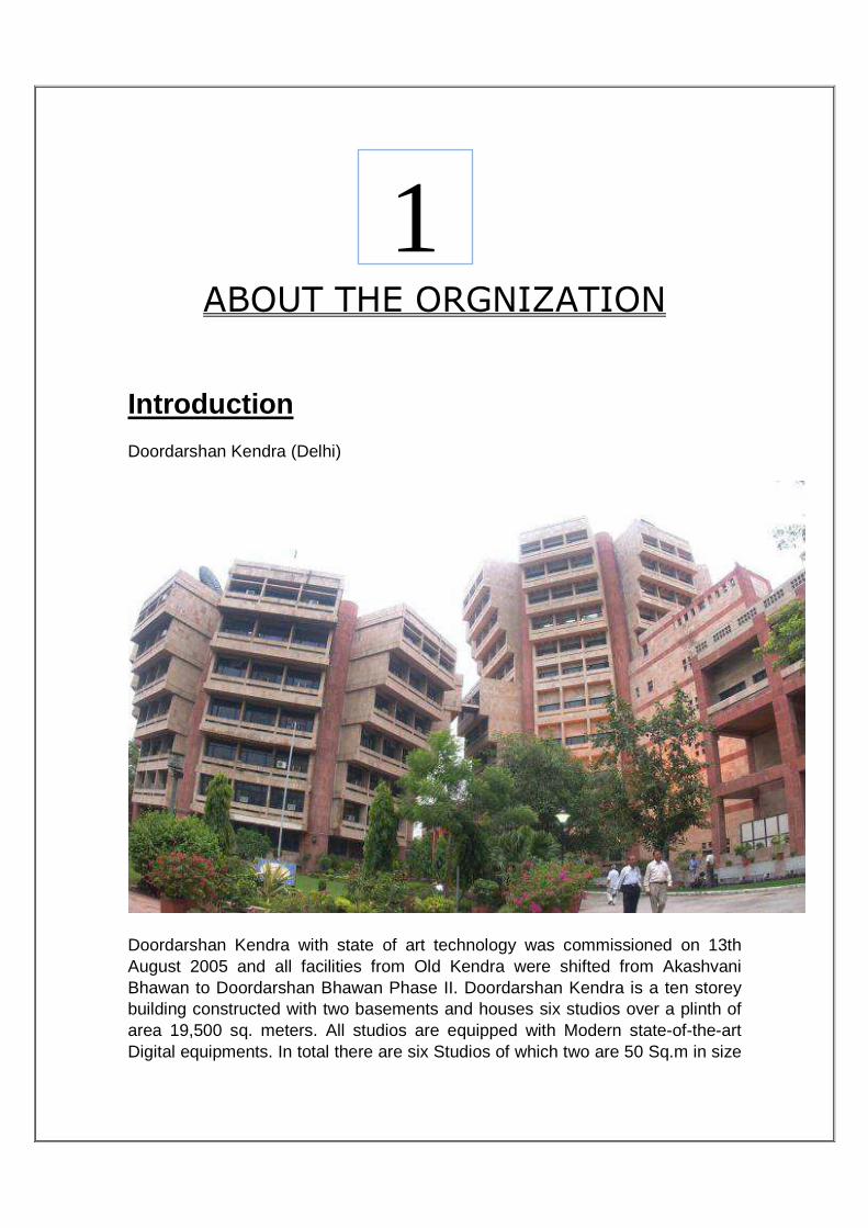
Studio Name Studio Size / Purpose Shows Recorded/ Live Broadcasted
Studio B (BIG) It’s the biggest Studio ~ 40’x120’x50’ Cubic Ft.
Fourth Umpire Meri Baat Youth Express Krishi Darshan –Live and Recordings
Studio L (Large) Its approx. of half the Studio-B.
Urdu News (Live and Recording)
Studio M (Medium) Same as the size of Studio L
Aaj Savere Patrika Krishi Darshan - Recordings
Studio S (Small) Approx. 15’x20’x12’ English News Hindi News
Procedure in recording 1. Set is designed in studio as per conceptual thought of program producer. 2. Floor plan is envisaged. 3. Lighting, Audio and placement of the cameras is arranged as per floor plan. 4. Pre testing of cameras, microphones, VCRs etc. is done before recording. 5. Recording begins and desired camera/mike are selected through VM/Audio console as per command of producer. Program is recorded on VCR. Procedure in Transmission 1. The programs are transmitted as per the daily cue sheet. 2. Normal transmission hours are 1600-2000Hrs. 3. Cue sheet is discussed daily by program and technical staff for details in it and for any last moment changes if any. 4. After getting D-link caption from Delhi end program is played from VCR/Server. The program is uplinked by Earth Station. 5. The program is also transmitted to transmitter at Pitampura via MW link. Then DD channels are taken on air. 6. During our slot, both live as well as recorded programs are transmitted.

STUDIO CENTRE A Studio centre of Doordarshan has the following objectives:
1) To originate programmes from studios either for live telecast or for recording on a video tape.
2) To knit various other sources of programs available at the production desk i.e., camera output from studios, feed from other kendras, outdoor, playback from pre recorded tape, film based programs slides, video graphics and characters generator etc. This knitting or live editing includes generation of special effects and desired transitions between various sources.
3) Processing/distribution of different sources to various destinations in technical areas.
4) Routing of mixed programme for recording/transmission via master switching room and Micro Wave to the transmitter or any other desired destinations.
Activities in a television studio can be divided in to three major areas such
as : 1) Action area, 2) Central apparatus room, 3) Production control room,

1) Action area
This place requires large space and ceiling as compared to any other technical area. Action in this area includes staging, lighting, performance by artists, and arrangement to pick up picture and sound. Hardware required for these activities in a studio (typical size 20 x20x8.5 cubic meters) are: 1. Very efficient air conditioning because of lot of heat dissipation by studio light
and presence of large number of persons including invited audience performing artists and operational crew.
2. Uniform and even flooring for smooth operation of camera dollies and boom microphone etc.
3. Acoustic treatment Keeping in mind that a television studio is a multi purpose studio with lot of moving person and equipment during a production. 4. Supporting facilities like properties, wardrobe, and makeup etc. 5. Effective communication facilities for the floor crew with the production control area. 6. Studio cameras (three to four) with one of the cameras fitted with teleprompter
system and pressure dolly. 7. Luminaires and suspension system having grids or battens (hand/motorised
operation). 8. Pick up wall sockets for audio operations. 9. Tie lines box for video and audio lines from control room 10. Cyclorama and curtain tracks for blue and black curtain for chroma keying
and limbo lighting respectively. 11. Audio and video monitoring facilities. 12. Studio warning light and safety devices like fire alarm system and fire fighting equipments etc. 13. Digital clock display: Operational requirement from the technical crew may
vary from programme to programme. These requirements for lighting, audio pick up and special effects etc. depends upon the programme requirement such as establishing a period, time, formal or informal situation.
TV Camera

A TV Camera consists of three sections : a) A Camera lens and optical block b) A transducer or pick up device c) Electronics CAMERA LENS The purpose of the camera lens is to focus the optical energy at the face plate of a pickup device i.e. to form an optical image. The lens has following sections: 1. Main focus section 2. Zoom section with manual or servo mode operation 3. Servo drive assembly for Zoom and iris control 4. Aperture section with manual or auto mode 5. Back focus section with adjustment facilities for back and micro Focus.
TRANSDUCER/ PICK UP DEVICE R, G & B signals, as separated by the optical block are converted to electrical signal in the transducer section of the camera. It is then processed in camera electronics to give CCVS (color composite video signal) output. LIGHTING
Lighting for television is very exciting and needs creative talent. There is always a tremendous scope for doing experiments to achieve the required effect. Light is a kind of electromagnetic radiation with a visible spectrum from red to violet i.e. wavelength from 700nm to 3800nm respectively.
Basic three pointing lighting:
• Key light: It gives shape and modelling by a casting shadow. It is treated as a sun in the sky and should cast only one shadow.
• Fill light: Controls the lighting contrast by filling in shadows. It can also provide catch lights in the eyes.
Object Side Camera Side 1 2
3 4 5

• Back light : Separates the body from the background, gives roundness to the subject and reveals texture.
Type Intensity of lighting Key Light 100% Fill Light 80% Back Light 110% Back Ground Light 50-60%
Lighting Equipments:
• 0HMI lights : compared to standard incandescent lights deliver five times
the light output per watt. They generate less heat, which is an important consideration when shooting inside in a confined space. (HMI stands for Hydrargyrum Medium Arc-length Iodide). The light on the left side of this picture is a HMI light; the one on the right a standard quartz light.
• Cycs: (large, seamless, neutral backgrounds) can be lit from the top and
bottom with cyclights. The one here sits on the studio floor and is directed up at the background.

MICROPHONE
A microphone is an acoustic-to electric transducer or sensor that converts sound into an electrical signal. Types of micro phones:
• Condenser Microphone: In a condenser microphone also called a capacitor microphone or electrostatic microphone, the diaphragm acts as one plate of a capacitor, and the vibrations produce changes in the distance between the plates.
• Electret Condenser Microphone: An electret is a ferroelectric material that has been permanently electrically charged or polarized. The name comes from electrostatic and magnet; a static charge is embedded in an electret by alignment of the static charges in the material, much the way a magnet is made by aligning the magnetic domains in a piece of iron.
• Dynamic Microphone: Dynamic microphones work via electromagnetic induction. They are robust, relatively in expensive and resistant to moisture. This coupled with their potentially high gain before feedback makes them ideal for on-stage use. Moving coil microphones use same dynamic principle as in loudspeaker.
• Ribbon Microphone: Ribbon microphones use a thin, usually corrugated metal ribbon suspended in a magnetic field. The ribbon is electrically connected to the microphone's output, and its vibration within the magnetic field generates the electrical signal. Ribbon microphones are similar to moving coil microphones in the sense that both produce sound by means of magnetic induction.
• Laser Microphone: Laser microphones are often portrayed in movies as spy gadgets. A laser beam is aimed at the surface of a window or other plane surface that is affected by sound. The slight vibrations of this surface displace the returned beam, causing it to trace the sound wave. The vibrating laser spot is then converted back to sound. In a more robust and expensive implementation, there turned light is split and fed to an interferometer, which detects movement of the surface.
• Fiber Optic Microphone: A fiber optic microphone converts acoustic waves into electrical signals by sensing changes in light intensity, instead of sensing changes in capacitance or magnetic fields as with conventional microphones.
• Piezoelectric Microphone: A crystal microphone or pizo microphone uses the phenomenon of piezoelectricity the ability of some materials to produce a voltage when subjected to pressure to convert vibrations into
an electrical signal.
MICROPHONES SENSITIVITY
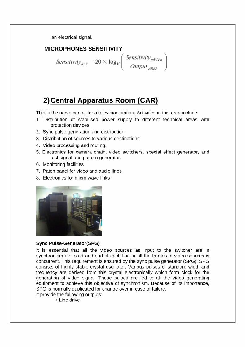
2) Central Apparatus Room (CAR) This is the nerve center for a television station. Activities in this area include: 1. Distribution of stabilised power supply to different technical areas with
protection devices. 2. Sync pulse generation and distribution. 3. Distribution of sources to various destinations 4. Video processing and routing. 5. Electronics for camera chain, video switchers, special effect generator, and
test signal and pattern generator. 6. Monitoring facilities 7. Patch panel for video and audio lines 8. Electronics for micro wave links
Sync Pulse-Generator(SPG) It is essential that all the video sources as input to the switcher are in synchronism i.e., start and end of each line or all the frames of video sources is concurrent. This requirement is ensured by the sync pulse generator (SPG). SPG consists of highly stable crystal oscillator. Various pulses of standard width and frequency are derived from this crystal electronically which form clock for the generation of video signal. These pulses are fed to all the video generating equipment to achieve this objective of synchronism. Because of its importance, SPG is normally duplicated for change over in case of failure. It provide the following outputs:
• Line drive

• Field drive • Mixed blanking • Mixed sync • colour subcarrier • A burst insertion pulse • PAL phase Indent pulses
Genlock (slaving) Often in a production it is necessary to mix between two sources whose waveforms are not synchronised. This is not possible until the local SPG has been synchronised with the external source so that the locally produced signals arrive at the mixer in synchronisation with the external source. When this occurs mixing is possible, captions, and credits produced locally can be superimposed on external sources. For non Synchronous sources mixing and super imposition is not possible and the signal can only be ‘cut to’ with a resulting disturbance in outgoing sync pulses which may cause frame rolls on monitors and certainly disturbance to VTR machine which is recording. To overcome this problem, SPG is fitted with a GENLOCK facility, which allows the master oscillator to lock to the incoming waveform from the remote source, which then synchronises both waveforms. A more modern method of synchronization is with a digital synchronizer called Frame synchronizers. Other technical areas associated with central apparatus room (CAR) are 1. Camera control unit (CCU) 2. Light control unit(LCU) and a dimmer room 3. Audio control room (ACR) 4. Video tape recording room(VTR) 5. Telecine(TK) and film section 6. Digital library store(DLS) 7. Video graphic or paint box(PB) 8. Post production and editing suites for outdoor works by the ENG/EFP section (Electronics News gathering/Electronic field production).
Camera Control Unit (CCU) The television cameras which include camera head with its optical focusing lens, pan and tilt head, video signal pre-amplifier view finder and other associated electronic circuitry are mounted on cameras trolleys and operate inside the studios. The output of cameras is pre-amplified in the head and then connected to the camera control unit (CCU) through triax cable. All the camera control voltages are fed from the CCU to the camera head over the camera cable. The view-finder signal is also sent over the camera cable to

the camera head view-finder for helping the cameraman in proper focusing, adjusting and composing the shots. The video signal so obtained is amplified, H.F. corrected, equalized for cable delays, D.C. clamped, horizontal, and vertical blanking pulses are added to it. The peak white level is also clipped to avoid overloading of the following stages and avoiding over modulation in the transmitter. The composite sync signals are then added and these video signals are fed to a distribution amplifier, which normally gives multiple outputs for monitoring etc.
Light Control Unit
The scene to be televised must be well illuminated to produce a clear and noise free picture. The lighting should also give the depth, the correct contrast and artistic display of various shades without multiple shadows. The lighting arrangements in a TV studio have to be very elaborate. A large number of lights are used to meet the needs of ‘key’, ‘fill’, and ‘back’ lights etc. Lights are classified as spot and soft lights. These are suspended from motorized hoists and telescopes. The up and down movement is remotely controlled. The switching on and off the lights at the required time and their dimming is controlled from the light control panel inside a lighting control room using SCR dimmer controls. These remotely control various lights are inside the studios. Modern TV studios have a computer-controlled lighting system. The intensities of various lights can be adjusted independently and memorised for reproduction. The status indication of lights regarding their location and intensity is available on a monitor/MIMIC display. During reproduction of a particular sequence, the information from the memory operates the respective light dimmers. Hand held control boxes are also available for controlling light intensities inside the studios which communicate via a control panel. Most of the operational controls of the computerised light control system can also be performed manually with the back –up matrix and fader controls.
Audio Control Room
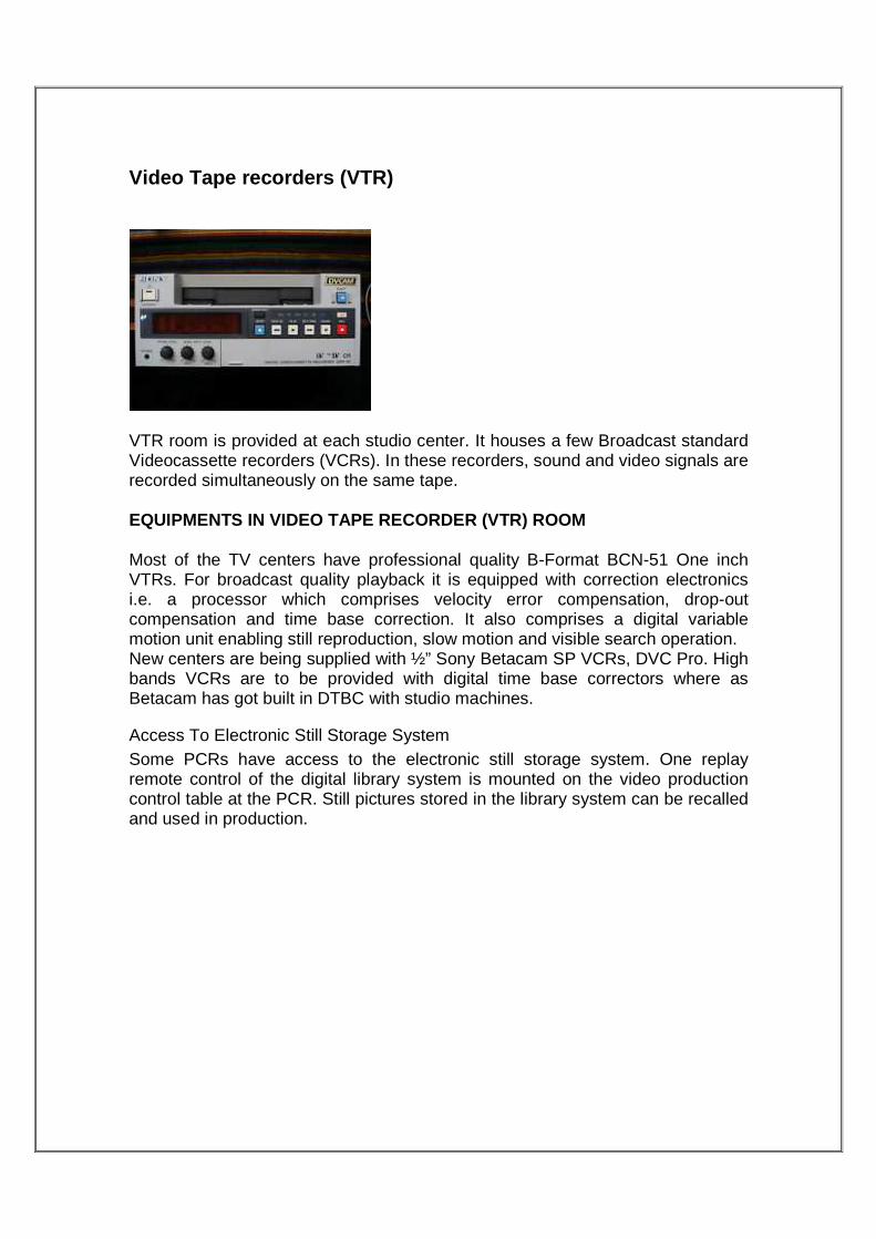
Video Tape recorders (VTR)
VTR room is provided at each studio center. It houses a few Broadcast standard Videocassette recorders (VCRs). In these recorders, sound and video signals are recorded simultaneously on the same tape.
EQUIPMENTS IN VIDEO TAPE RECORDER (VTR) ROOM
Most of the TV centers have professional quality B-Format BCN-51 One inch VTRs. For broadcast quality playback it is equipped with correction electronics i.e. a processor which comprises velocity error compensation, drop-out compensation and time base correction. It also comprises a digital variable motion unit enabling still reproduction, slow motion and visible search operation. New centers are being supplied with ½” Sony Betacam SP VCRs, DVC Pro. High bands VCRs are to be provided with digital time base correctors where as Betacam has got built in DTBC with studio machines.
Access To Electronic Still Storage System Some PCRs have access to the electronic still storage system. One replay remote control of the digital library system is mounted on the video production control table at the PCR. Still pictures stored in the library system can be recalled and used in production.

3) Production control area
or
PRODUCTION CONTROL ROOM (PCR) Activities in this area are:-
1. Direction to the production crew by the producer of the programme. 2. Timing a production/telecast. 3. Editing of different sources available at the production desk. 4. Monitoring of output/off air signal.
Hardware provided in this area include:
1. Monitoring facilities for all the input and output sources(audio/video). 2. Remote control for video mixer, telecine and library store and special effect
(ADO) etc. 3. Communication facilities with technical areas and studio floor.
Video Signal Generation Video is nothing but a sequence of pictures. The image we see is maintained in our eye for 1/16sec. So if we see images at the rate more than 16 pictures/sec, our eyes cannot recognize the difference and we see the continuous motion. In movies camera and movie projector it is found that 24 fps is better for human eyes. TV system could also use this rate but in PAL system 25fpm is selected. In TV cameras image is converted in electrical signal using photosensitive material. Whole image is divided into many micro particles known as pixels. These pixels are small enough so that our eyes cannot recognize pixels and we see continuous image. Thus, at any particular instance there are almost infinite numbers of pixels that need to be converted in electrical signal simultaneously for transmitting picture details. However this is not possible practical because it is no feasible to provide a separate path for each pixel. In practice this problem is solved by method known as Scanning in which information is converted one by one pixel, line by line and frame by frame. Color Composite Video Signals Active waveform comprises of 2 signals: Luminance (Y)-black and white Chrominance (C)- color signal
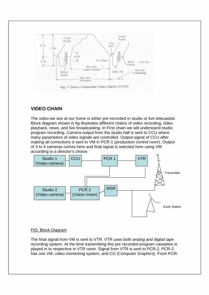
VIDEO CHAIN The video we see at our home is either pre-recorded in studio or live telecasted. Block diagram shown in fig illustrates different chains of video recording, video playback, news, and live broadcasting. In First chain we will understand studio program recording. Camera output from the studio hall is sent to CCU where many parameters of video signals are controlled. Output signal of CCU after making all corrections is sent to VM in PCR-1 (production control room). Output of 3 to 4 cameras comes here and final signal is selected here using VM according to a director’s choice.
FIG: Block Diagram The final signal from VM is sent to VTR. VTR uses both analog and digital tape recording system. At the time transmitting this pre recorded program cassettes is played in to respective in VTR room. Signal from VTR is sent to PCR-2. PCR-2 has one VM, video monitoring system, and CG (Computer Graphics). From PCR-
Studio 1 (Video camera)
CCU PCR 1
Studio 2 (Video camera)
PCR 2 (Vision mixer)
MSR
VTR
Earth Station
Transmitter

2, signal travels from MSR to Transmitter or Earth station for terrestrial and satellite transmission. MSR is the main control room between studio and transmitter or receiver. AUDIO CHAIN In studio program, audio from studio microphones is directly fed to the AUDIO CONSOLE place in PCR-1. It is used to mix audio from different sources and maintain its output. From AC, signal is directly recorded on tape with video signal in VTR. While playing back audio is extracted from tape and fed to another audio console placed in PCR-2 and then travels with the video signal.
Vision Mixer (or Video Switcher)
Vision mixing and switching
Unlike films, television media allows switching between different sources simultaneously at the video switcher in Production control room operated by the Vision Mixer on the direction of the program producer. The producer directs the cameramen for proper shots on various cameras through intercom and the vision mixer (also called VM engineer) switches shots from the selected camera/cameras with split second accuracy, in close cooperation with the producer. The shots can be switched from one video source to another video source, superimposed, cross faded, faded in or faded out electronically with actual switching being done during the vertical intervals between the picture
Pre-
Pre-
Pre-
VTR
CD/V
Outsid
Satellit
MW
Audio console
Program Audio distan. Ampl.
MSR
MSR
MW
FEED VTR FOR
Program Ampl. ADA
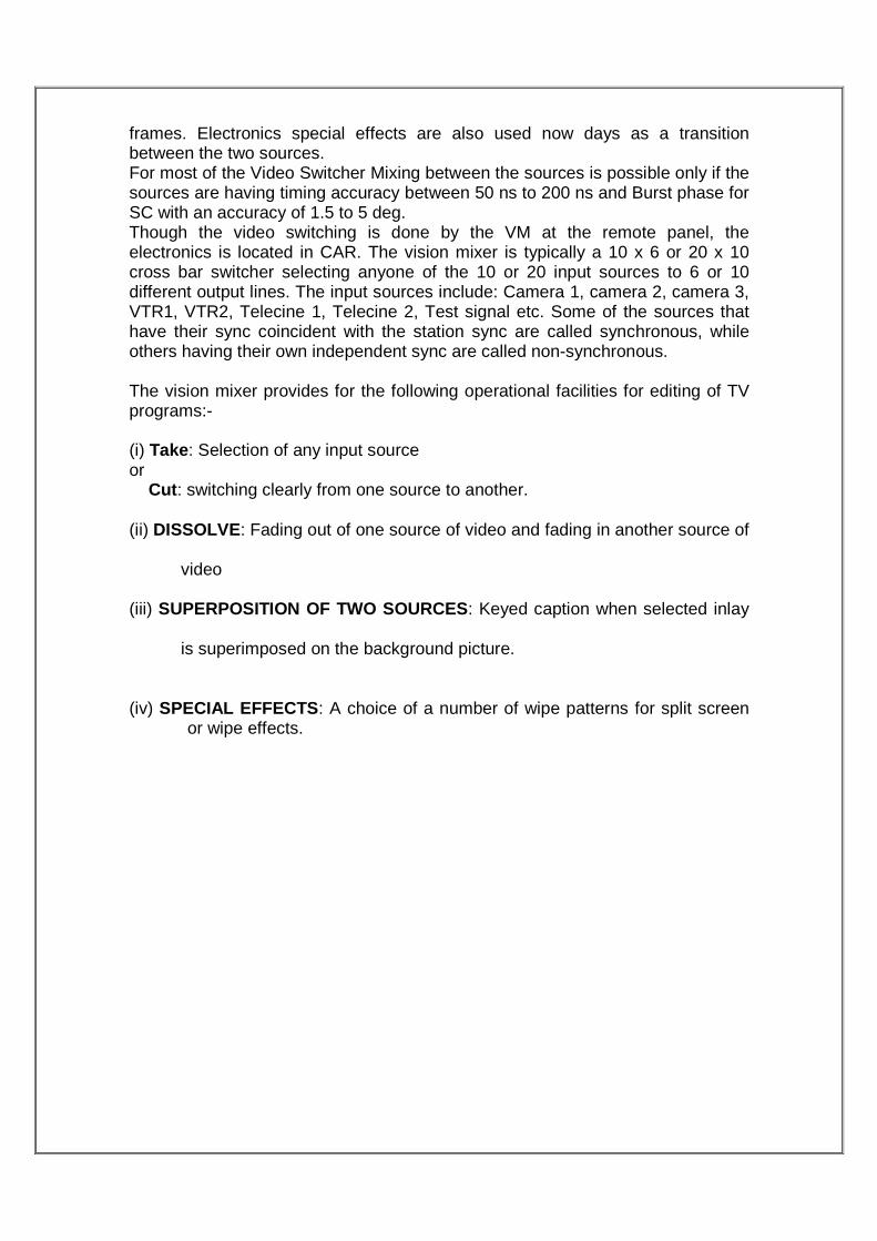
frames. Electronics special effects are also used now days as a transition between the two sources. For most of the Video Switcher Mixing between the sources is possible only if the sources are having timing accuracy between 50 ns to 200 ns and Burst phase for SC with an accuracy of 1.5 to 5 deg. Though the video switching is done by the VM at the remote panel, the electronics is located in CAR. The vision mixer is typically a 10 x 6 or 20 x 10 cross bar switcher selecting anyone of the 10 or 20 input sources to 6 or 10 different output lines. The input sources include: Camera 1, camera 2, camera 3, VTR1, VTR2, Telecine 1, Telecine 2, Test signal etc. Some of the sources that have their sync coincident with the station sync are called synchronous, while others having their own independent sync are called non-synchronous. The vision mixer provides for the following operational facilities for editing of TV programs:- (i) Take: Selection of any input source or Cut : switching clearly from one source to another.
(ii) DISSOLVE: Fading out of one source of video and fading in another source of
video
(iii) SUPERPOSITION OF TWO SOURCES: Keyed caption when selected inlay
is superimposed on the background picture.
(iv) SPECIAL EFFECTS : A choice of a number of wipe patterns for split screen or wipe effects.

The selected output can be monitored in the corresponding pre-view monitor. All the picture sources are available on the monitors. The preview monitors can be used for previewing the telecine, VTR; test signals etc. with any desired special effect, prior to its actual switching. STI(T) Publication 153 001/BC/2005 Basic Course The switcher also provides cue facilities to switch camera tally lights as an indication to the cameraman whether his camera is on output of the switcher. Vision mixer is the almost final equipment in program (video) production and its output is used either for recording or transmission. Vision mixing is the process of providing a composite signal from various input sources. It has many input sources such as cameras, VCR/server, Graphics, IRD’s. Out of these I/ p, any source can be taken on o/p. It is used to switch or cut between 2 video sources, or to combine them in a variety of ways. There are two types of mixing: > Additive mixing &
� Non additive mixing
Present day PCR’s have: • 24 input video special effects switchers • (CD 680 or CD 682-SP) • Digital video effects- type ADO-2000/ADO-1000/ADO-100(Ampex) • Character generators • Telecine/DLS remote controls • Adequate monitoring equipment

Sound mixing and control
As a rule, in television, sound accompanies the picture. Several microphones are generally required for production of complex television programs besides other audio .
Audio facilities
An audio mixing console, with a number of inputs, say about 32 inputs is provided in major studio. This includes special facilities such as equalisation, PFL, phase reversal, echo send/receive and digital reverberation units at some places Meltron console tape recorders and EMI 938 disc reproducers are provided for playing back/creating audio effects as independent sources (Unmarried) to the switcher.
Post Production Suites Modern videotape editing has revolutionised the production of television programs over the years. The latest trend all over the world is to have more of fully equipped post production suites than number of studios. The actual production is done in these suites. The job for a post production suites is:- a. To knit program available on various sources. b. While doing editing with multiple sources, it should be possible to have any
kind of transition. c. Adding/Mixing sound tracks. d. Voice over facilities. e. Creating special effects. The concept of live editing on vision mixer is being replaced by “to do it at leisure” in post production suites. A well equipped post production suite will have:- 1. Five VTRs/VCRs, may be of different format remotely controlled by the editor. 2. Vision mixing with special effect and wipes etc. with control from a remote
editor panel. 3. Audio mixer with remote control from the editor remote panel. 4. Multi-track audio recorder with time code facilities and remote operation. 5. Adequate monitoring facilities. 6. Non Linear Editing System 7. 3-D Graphics

Linear and Non-Linear editing LINEAR EDITING
The Linear editing is sequential kind of editing where continuous editing is done. We cant reach the exact point of interest where we need to do the editings.
DISADVANTAGES
• Low S/N ratio. • High Noise. • Editing become Problematic. • Time Taking.
NON LINEAR EDITING (NLE) Fundamentally editing is a process where one places Audio video clips in an appropriate sequence and mainly used in video post-production . Linear editing is tape based and is sequential in nature. It has various problems like long hours spent on rewinding of tapes in search of material, potential risk of damage to original footage, difficult to insert a new shot in an edit, difficult to experiment with variations, quality loss is more, limited composting effects and color correction capability. Non-linear editing (NLE) is a video editing in digital format with standard computer based technology. NLE can also be extended to film editing. Computer technology is harnessed in Random access, computational and manipulation capability, multiple copies, multiple versions intelligent search, sophisticated project and media management tools, standard interfaces and powerful display.
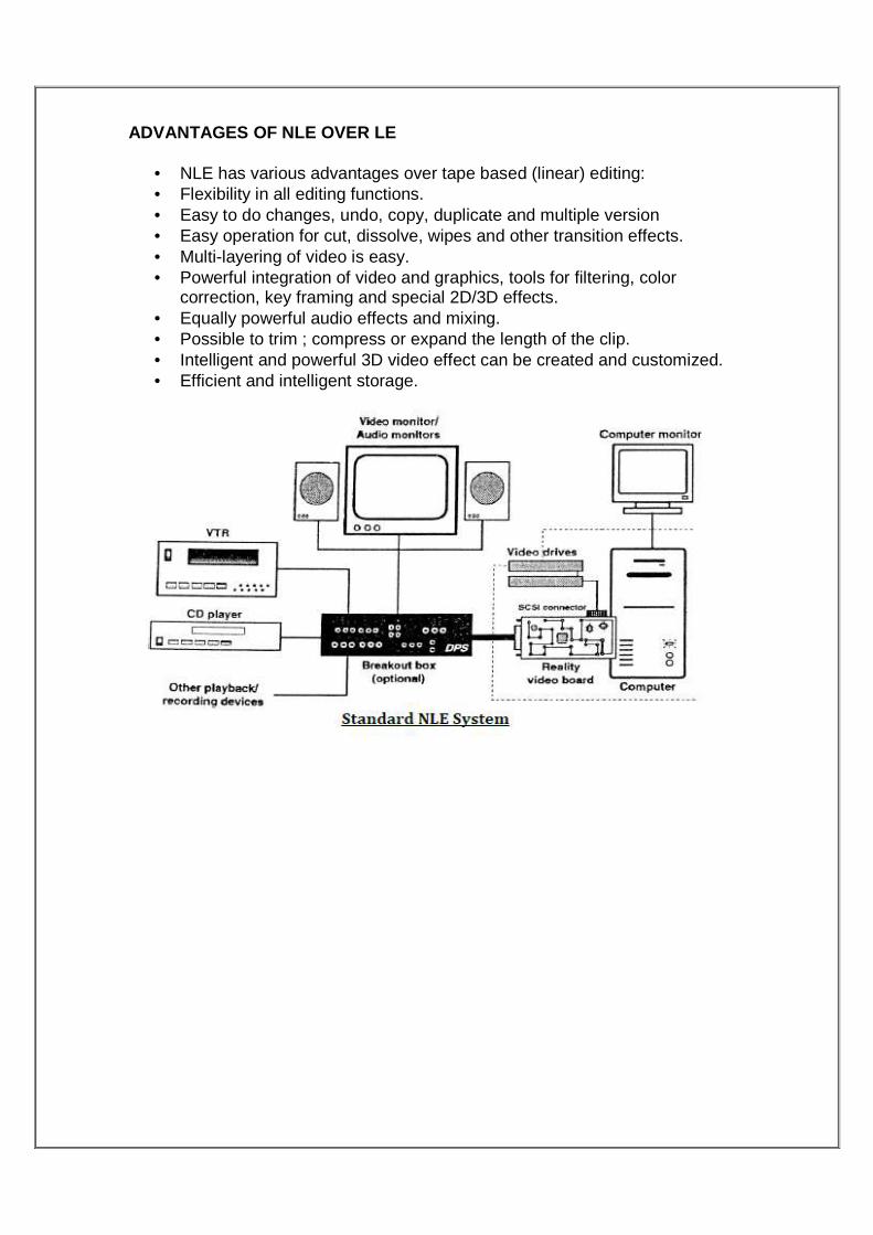
ADVANTAGES OF NLE OVER LE
• NLE has various advantages over tape based (linear) editing: • Flexibility in all editing functions. • Easy to do changes, undo, copy, duplicate and multiple version • Easy operation for cut, dissolve, wipes and other transition effects. • Multi-layering of video is easy. • Powerful integration of video and graphics, tools for filtering, color
correction, key framing and special 2D/3D effects. • Equally powerful audio effects and mixing. • Possible to trim ; compress or expand the length of the clip. • Intelligent and powerful 3D video effect can be created and customized. • Efficient and intelligent storage.

MASTER SWITCHING ROOM (MSR)
Master switching room (MSR) is used for transmission media. It is the engineering co-ordination centre of activity for selecting & routing the signal from various sources to transmitter and earth station. It is a room where all different sources from the outside studio comes first here and enroots transmission to different destination like transmitter & earth station. This room comprises of Routine switcher, Stab amplifier, Video/Audio distribution amplifier etc. It is the heart of the studio. ‡Most of the switching electronics are kept here e.g. camera base stations, switcher mainframe, SPG, Satellite receivers, MW link, DDA & most of the patch panels. Signal is routed through MSR. Signal can be monitored at various stages. This section is equipped with a 64X64 Digital Routing Switcher where all the signals from Studio-A, Studio-B, Transmitter, Earth Station, OB Van signal, DSNG etc are routed to various areas as per requirements for recording/transmission. One OFC link between MSR and Earth Station has also been installed.
Equipments Installed • Router (64 X 64) • Audio/Video Switcher • OFC RACK • FRAME SYNCHRONISER • DVDs and AVDs • D/A and A/D converters • SPG • IRDs
3

MASTER SWITCHING ROOM WHEN SOURCE IS ANTENNA
WHAT MSR DOES? The Master Switching Room or Master Control Room (MSR/M CR) houses equipment that is too noisy or runs too hot for the Production control room (PCR). It also makes sure that coax cable and other wire lengths and installation requirements keep within manageable lengths, since most high-quality wiring runs only between devices in this room. This can include the actual circuitry and connections between all specifies devices.

MASTER SWITCHING ROOM WHEN SOURCE IS PCR
DEVICES USED DETAILS
1. IRDs
An Integrated Receiver Decoder (IRD) is an electronic device used to pick-up a radio-frequency signal and convert digital information transmitted in it. The IRD is the interface between a receiving satellite dish networks and a broadcasting facility video/audio infrastructure. The IRDs used in MSR feed Room at DDK Mandi House is 16x16. i.e. each source can be passed to 16 destinations which makes transmission easy. Including this, 32x32 type is also used.
A TYPICAL IRD
2. VTRs
A video tape recorder (VTR) is a tape recorder designed to record video material, usually on magnetic tape . VTRs originated as individual tape reels, serving as a replacement for motion picture film stock and making recording for television applications cheaper and quicker. It is very similar to VCRs and VDRs.

A TYPICAL VTR
3. DVDAs
it amplifies the Digital Video signals and route them to the defined video displays. It is the device used in MSR and PCR to view the video signals on more than one interface.
DVDA with Waveform Monitor and a TV Display
4. FS (FRAME SYNCHRONISER)
A frame synchronizer is a device used in live television production to match the timing of an incoming video source to the timing of an existing video system. They are often used to "time in" consumer video equipment to a professional system but can be used to stabilize any video. The frame synchronizer essentially takes a picture of each frame of incoming video and then immediately outputs it with the correct synchronization signals to match an existing video system.

A typical frame synchroniser
5. SPG (SYNC PULSE GENERATOR)
A sync pulse generator is a special type of generator which produces synchronization signals, with a high level of stability and accuracy. These devices are used to provide a master timing source for a video facility. The output of an SPG will typically be in one of several forms, depending on the needs of the facility.

MODES OF TRANSMISSION
The signal generated or to be received can be transmitted by one of these techniques :
• Satellite • Microwave • Optical fibre cable (OFC) • DSNG
SATELLITE TRANSMISSION
This is the most widely used means of transmission. Satellite transmission requires an unobstructed line of sight. The line of site will be between the orbiting satellite and a station on Earth. Satellite signals must travel in straight lines but do not have the limitations of ground based wireless transmission, such as the curvature of the Earth.
Microwave signals from a satellite can be transmitted to any place on Earth which means that high quality communications can be made available to remote areas of the world without requiring the massive investment in ground-based equipment. This is better discussed in Earth station section.
4

MICROWAVE TRANSMISSION
Microwave transmission refers to the technology of transmitting information or energy by the use of radio waves whose wavelengths are conveniently measured in small numbers of centimeter, these are called microwaves. Microwaves are widely used for point-to-point communications because their small wavelength allows conveniently-sized antennas to direct them in narrow beams, which can be pointed directly at the receiving antenna. This is better discussed in Pitampura visit section. OPTICAL FIBRE CABLE
An optical fiber cable is a cable containing one or more optical fibers. The optical fiber elements are typically individually coated with plastic layers and
contained in a protective tube suitable for the environment where the cable will be deployed. Optical fiber consists of a core and a cladding layer, selected for total internal reflection due to the difference in the refractive index between the two. In practical fibers, the cladding is usually coated with a layer of acrylate polymer or polyimide. This coating protects the fiber from damage but does not contribute to its optical waveguide properties. Individual coated fibers (or fibers formed into ribbons or bundles) then have a tough resin buffer layer and/or core tube(s) extruded around them to form the cable core. Several layers of protective sheathing, depending on the application, are added to form the cable. Rigid fiber assemblies sometimes put light-absorbing ("dark") glass between the fibers, to prevent light that leaks out of one fiber from entering another. This reduces cross-talk between the fibers, or reduces flare in fiber bundle imaging applications.
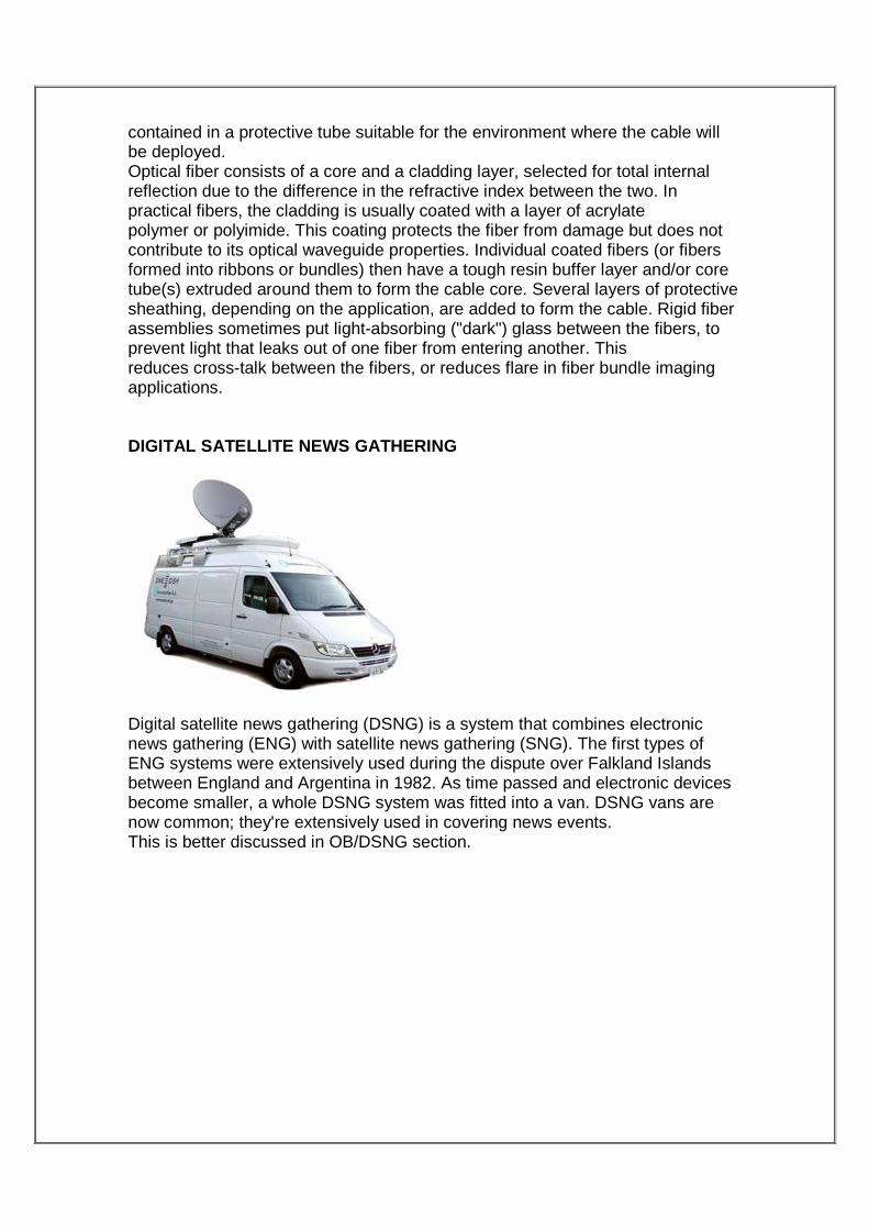
DIGITAL SATELLITE NEWS GATHERING
Digital satellite news gathering (DSNG) is a system that combines electronic news gathering (ENG) with satellite news gathering (SNG). The first types of ENG systems were extensively used during the dispute over Falkland Islands between England and Argentina in 1982. As time passed and electronic devices become smaller, a whole DSNG system was fitted into a van. DSNG vans are now common; they're extensively used in covering news events. This is better discussed in OB/DSNG section.

EARTH STATION
INTRODUCTION An earth station, ground station, or earth terminal is a terrestrial terminal station designed for extraplanetary telecommunication with spacecraft, and/or reception of radio waves from an astronomical radio source. Earth stations are located either on the surface of the Earth, or within Earth's atmosphere. Earth stations communicate with spacecraft by transmitting and receiving radio waves in the super high frequency or extremely high frequency bands (e.g., microwaves). When an earth station successfully transmits radio waves to a spacecraft (or vice versa), it establishes a telecommunications link. When a satellite is within an earth station's line of sight, the earth station is said to have a view of the satellite. It is possible for a satellite to communicate with more than one earth station at a time. A pair of earth stations are said to have a satellite in mutual view when the stations share simultaneous, unobstructed, line-of-sight contact with the satellite. There are currently three classes of earth stations: Mass capacity station --Designed for large users or inter-exchange carrier applications. This type of earth station serves a user community with communications needs great enough to require feeder line access to the earth station. The cost for earth stations in this class runs into millions of dollars. Middle range earth station --Designed for large corporate applications. This type of earth station serves a single large user (e.g. newspaper publisher, financial institution, etc). The cost for earth stations in this class run into the hundreds of thousands of dollars.
5

Low-end earth station --Designed for smaller corporate applications. This type of earth station serves a single user (e.g., retailers, general business, etc) and is typically designed to handle data traffic (e.g., point-of-sale information, inventory control, credit authorization, and other types of remote processing). These types of earth stations are established with a minimal amount of equipment and a very small aperture terminal (VSAT).
SATELLITE COMMUNICATION Satellite Communication is the outcome of the desire of man to achieve the concept of global village. Penetration of frequencies beyond 30 Mega Hertz through ionosphere force people to think that if an object (Reflector) could be placed in the space above ionosphere then it could be possible to use complete spectrum for communication purpose. Intelsat-I (nick named as Early Bird) was launched on 2 April 1965. This was parked in geosynchronous orbit in Atlantic ocean and provided telecommunication or television service between USA and Europe. It had capacity for 240 one way telephone channels or one television channel. Subsequently Intelsat-II generation satellites were launched and parked in Atlantic ocean and Pacific Ocean. During Intelsat III generation, not only Atlantic and Pacific ocean got satellites but also Indian Ocean got satellite for the first time. Now Arthur C.Clarke‟s vision of providing global communication using three Satellites with about 120 degrees apart became a reality. So far Intelsat has launched 7 generations of geosynchronous satellites in all the three regions namely Atlantic Ocean, Pacific Ocean and Indian Ocean.
Architecture of a Satellite Communication System The Space Segment The space segment contains the Satellite and all terrestrial facilities for the control and monitoring of the Satellite. This includes the tracking, telemetry and command stations (TT&C) together with the Satellite control centre where all the operations associated with station-keeping and checking the vital functions of the satellite are performed. In our case it is Master Control Facility (MCF) at Hassan. The radio waves transmitted by the earth stations are received by the satellite ; this is called the up link. The satellite in turn transmits to the receiving earth stations ; this is the down link. The quality of a radio link is specified by its carrier-to-noise ratio. The important factor is the quality of the total link, from station to station, and this is determined by the quality of the up link and that of the down link. The quality of the total link determines the quality of the signals delivered to the end user in accordance with the type of modulation and coding used.

The Ground Segment The ground segment consists of all the earth stations ; these are most often connected to the end-user‟s equipment by a terrestrial network or, in the case of small stations (Very Small Aperture Terminal, VSAT), directly connected to the end-user‟s equipment. Stations are distinguished by their size which varies according to the volume of traffic to be carried on the space link and the type of traffic (telephone, television or data). The largest are equipped with antenna of 30 m diameter (Standard A of the INTELSAT network). The smallest have 0.6 m antenna (direct television receiving stations). Fixed, transportable and mobile stations can also be distinguished. Some stations are both transmitters and receivers
� Earth station involves the two terms which are basically the important parameters of the communication i.e.
UPLINK & DOWNLINK. UPLINK: The process of gathering any informative part & sending it to the satellite, running on specified frequency is termed as UPLINK. The uplink frequency is 5950MHz.

OUTPUT CHAIN OF EARTH STATION OR UPLINK 1. The information gets recorded is in the analog form which needs to be converted into digital form for long route transmission by encoder. 2. Moreover, Encoder also enables the compression technique. 3. Many digitalized signals are then feeded to multiplexer (many into one) so that we can have one output signal at a time. 4. This output signal has poor strength & power & not fit for the long distance transmission so its need to be pass through modulator where it superimpose on high power carrier signal. But modulator can raise its frequency up to 70MHz only. 5. After that IF switch selects one of the modulator o/p & divide it to 1:4 ratio. 6. It is then compared with Equalizer signal to limits its parameters like amplitude, phase etc. and also to compensate the effect of delay in the signal. 7. UPC (Up converter) increases the signal frequency to a range to reach to the satellite. This is done by mixing the signal with locally generated high frequency signal of oscillator. 8. It is then transmitted to RF selector switch where the signals gets partitioned & provided to two different HPA. 9. High power Amplifier (HPA) amplifies the signal to 750W. 10. The two signals are combined in combiner and transmitted through hollow rectangular waveguide (Now-a-days Travelling wave tubes ,TWT are also in use) to antenna & then to SATELLITE. 11. The uplink frequency assigned to Doordarshan service station is 5950 MHz. 12. All these signals are SD i.e. Standard definition, which uses 625 lines. 13. Very few signals are HD i.e. High definitions which uses 720 lines.
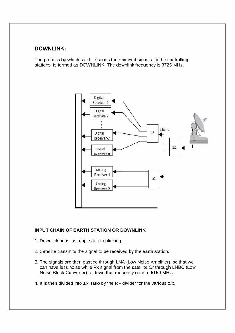
DOWNLINK: The process by which satellite sends the received signals to the controlling stations is termed as DOWNLINK. The downlink frequency is 3725 MHz.
INPUT CHAIN OF EARTH STATION OR DOWNLINK 1. Downlinking is just opposite of uplinking. 2. Satellite transmits the signal to be received by the earth station. 3. The signals are then passed through LNA (Low Noise Amplifier), so that we can have less noise while Rx signal from the satellite Or through LNBC (Low Noise Block Converter) to down the frequency near to 5150 MHz. 4. It is then divided into 1:4 ratio by the RF divider for the various o/p.

5. RF patch panel are used to monitor the signal at this point. 6. Now, incoming C band signals are converted into L band by C-L band down converter just to lower down the high frequency signals. 7. It is then divided into 1:4 ratio by the L band divider for the various o/p. 8. These four o/p are then passes through IRDs (Decoder) to convert them back to analog signals & then passes to Patch panel for monitoring purpose. 9. After this, through 40X40 SDI/ASI routers they are sent to Suit View Leitch (SVL). 10. The o/p of SVL enables us to view 8 channels simultaneously on single LCD (42”) monitor. 11. The downlinking procedure is done for monitoring purpose mostly, just to confirm that whatever we are uplinking are actually happening or not.

OB/DSNG VAN
Introduction Outside broadcasting is the production of television or radio programmes (typically to cover news and sports events) from a mobile television studio. This mobile control room is known as an "Outside Broadcasting Van", "OB Van", "Scanner" (a BBC term), "mobile unit", "remote truck", "live truck", or "production truck". Signals from cameras and microphones come into the OB Van for processing and transmission. The final output is then transferred to DSNG Van(Digital Satellite News Gathering) for Direct uplinking or transmission to MSR. The OB Van is known as the ‘Mobile Studio’ and the DSNG Van is also known as the “Mobile Earth Station’.
OB VAN OB Van is equipped with 8 numbers of Thomson TTV 1657 Digital CCD cameras, 16 input versatile vision mixers ROSS Synergy with various special effects. 16 channel Sound Craft make audio mixer with facility of individual channel equalization and limited. In addition to the above, one computerized MOVE CG for superimposing titles. Two nos. of broadcast quality VCR having slow motion (TTV3575p), two nos. of Recording VCRs and one EVS make Live slow motion hard disc recording system is also installed. One Long haul microwave link is also available with OB.
6

OB VAN IS EQUIPED WITH
1. Highly compact 20KVA On Line UPS system. 2. Mains and UPS Power Supply status (Aural & Visual) indication should be
made available in the Operational Area through Remote Monitoring Facility. It should be clearly visible and audible.
3. Power Distribution Rack with Metering facilities should be provided in the OB Van.
4. Internal lighting suitable for both TV Production and Operation & Maintenance should be provided in the OB Van.
5. Air Conditioners of adequate tonnage capacity especially concentrated for the equipment racks and comfortable for the Operators etc. will be part of the offer.
6. The OB Van should be equipped with equipment bays for Production, Recording, Super Slow Motion/Slow Motion Area, CCU, Monitoring and Test Equipment with an ease of access while servicing.
7. The OB Van should be provided with ergonomically & aesthetically designed Production, CCU, Audio, Recording, Super Slow Motion/ Slow Motion Area, End Control Desks and Video Monitoring walls etc.
8. Technical Furniture including Operator chairs etc. will also be part of the offer.
9. The OB Van should be provided with suitable storage area in the rear and both sides of the vehicle for Cameras, Lens, various cable drums and miscellaneous equipment etc.
10. The OB Van should have hydraulic stabilization jacks. 11. Portable Fire Fighting Extinguishers of suitable type in each partition
should also be provided.
A typical OB Van is usually divided into 5 parts:

> The 1st and largest part is the production area where the director, technical director, assistant director, character generator operator and producers usually sit in front of a wall of monitors. This area is very similar to a Production control room. The technical director sits in front of the video switcher. The monitors show all the video feeds from various sources, including computer graphics, cameras, video tapes, video servers and slow motion replay machines. The wall of monitors also contains a preview monitor showing what could be the next source on air and a program monitor that shows the feed currently going to air or being recorded. Behind the directors there is usually a desk with monitors for the editors to operate. It is essential that the directors and editor are in connection with each other during events, so that replays and slow-motion shots can be selected and aired. > The 2nd part of a van is for the audio engineer; it has a sound mixer. The audio engineer can control which channels are added to the output and will follow instructions from the director. >The 3rd part of van is video tape. The tape area has a collection of VTRs and may also house additional power supplies or computer equipment. > The 4th part is the video control area where the cameras are controlled by 1or 2 people to make sure that the iris is at the correct exposure and that all the cameras look the same. > The 5th part is transmission where the signal is monitored by and engineered for quality control purposes and is transmitted or sent to other trucks.

DSNG VAN The mobile DSNG Van is equipped with 400 W TWT of Xycom and Tandberg E5500 encoder in 1+1 mode along with up converters / down converters of ADVENT and base band equipments. The DSNG van can be operated in both C or Ku band and it has the unique dual band waveguide in it. The system is operational since November 2002 The 2 meter antenna system is of advent make having the auto tracking facility controlled through laptop computer and can track any satellite in very short period automatically. It has a GPS system with flux gate compass etc used for auto tracking of satellites. The vehicle mounted DSNG Van supplied through BECIL is used in live coverage’s for up linking.
TYPES OF DSNG VAN • Fly Away DSNG – Directly linked to receive terminals at the stations.
• Drive Away DSNG - In Drive Away DSNG System, the Satellite Antenna is mounted on the roof of a medium sized vehicle. All other equipments are mounted in the rack housed inside the vehicle. The programme uplinked through the Mobile DSNG Terminals are received directly by the Stations with the C-Band Receive Terminals at the Stations
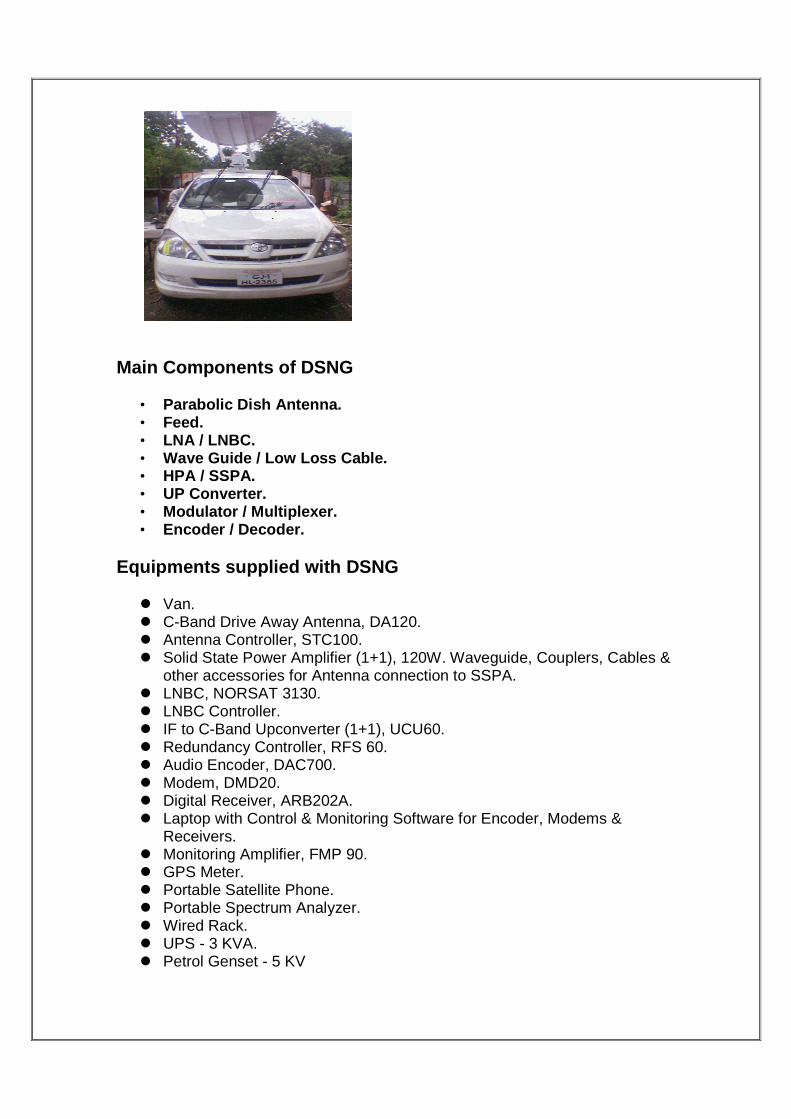
Main Components of DSNG
• Parabolic Dish Antenna. • Feed. • LNA / LNBC. • Wave Guide / Low Loss Cable. • HPA / SSPA. • UP Converter. • Modulator / Multiplexer. • Encoder / Decoder.
Equipments supplied with DSNG
� Van. � C-Band Drive Away Antenna, DA120. � Antenna Controller, STC100. � Solid State Power Amplifier (1+1), 120W. Waveguide, Couplers, Cables &
other accessories for Antenna connection to SSPA. � LNBC, NORSAT 3130. � LNBC Controller. � IF to C-Band Upconverter (1+1), UCU60. � Redundancy Controller, RFS 60. � Audio Encoder, DAC700. � Modem, DMD20. � Digital Receiver, ARB202A. � Laptop with Control & Monitoring Software for Encoder, Modems &
Receivers. � Monitoring Amplifier, FMP 90. � GPS Meter. � Portable Satellite Phone. � Portable Spectrum Analyzer. � Wired Rack. � UPS - 3 KVA. � Petrol Genset - 5 KV

Project Alloted: HDTV & SDTV
Digital television Digital television is a new way of broadcasting television signals. It is different from today’s way of doing it, known as ‘analog.’ In analog broadcasting the signal is in the form of a continuous wave form whereas a digital signal is in the form of discrete bits of information.
Digital television is better than analog for severa l reasons.
� Firstly, it provides clearer, sharper pictures. There is none of the interference and ghosting that people get today, especially if they live in built-up areas or hilly terrain.
� Secondly, it offers a wide screen format, such as we are used to seeing at the movies.
� Thirdly, digital television is very flexible. One moment you can be watching television; the next moment surfing the Internet; and next doing some home shopping. And it offers different types of television viewing – sometimes widescreen movie quality pictures, other times multiple camera angles (of the Grand Prix, for example) which you choose between.
� And fourthly, with digital television, you can fit many more television channels into a given amount of ‘radiofrequency spectrum’.
The change to digital television will also enable viewers to receive datacasting and enhanced television services which may include subtitles, captioning, further information on programming and a choice of viewing angles.
benefits with digital television
Digital television is a far more efficient and flexible transmission system than the current analog system. It allows broadcasters to offer viewers a range of new and different services. Digital television features can include:
• Much improved reception capability, including the elimination of ghosting and other transmission errors
• A 16 x 9 aspect ratio, or screen shape. This is also known as widescreen. It is similar to the aspect ratio that is widely used in the cinema.
7

• Standard Definition television (SDTV)
• High Definition television (HDTV)
• High quality audio
• Electronic Program Guides (EPGs). A basic EPG can be used by viewers to navigate between channels, identify the currently screening program and the next program ('now and next') on each channel. More sophisticated EPGs can be used to set reminders for program viewing, provide a short synopsis of the content of programs, identify programming in advance for several days, search for programs by genre, and provide access to some enhancements
• Multichannel programs
• Radio programs
• Program enhancements on separate channels to the primary program, eg, additional camera angles on a sports match, statistics about a player, or additional information about a segment in a lifestyle or magazine program
• Broadcasters will be allowed to broadcast more than one channel when certain events, such as sporting matches, extend beyond time due to circumstances beyond the broadcasters' control, and overlap a regularly scheduled news program. This will allow viewers the option of continuing to watch the end of the event or the news bulletin
• Over time, interactive television services and datacasting services, including selected Internet services, home shopping, computer games, etc will be provided by broadcasters and datacasters
Equipment required to receive digital television
� A fully integrated Digital Television or,
� A set-top box decoder to convert the digital signal back to analog form for existing analog televisions.
Viewers will be able to access most of the enhanced features of the digital signal, including clearer pictures and improved reception in built-up areas. The set-top box, however, will not cause an analog television to display a high definition picture. With the addition of a set-top box, an analog television will either display the images in the current 4:3 aspect ratio (width relative to height) or in a widescreen 16:9 ratio with the addition of black bands above and below the image.

Integrated Digital television receiver (IDTV) This is a television set which contains all the components necessary to receive and display digital transmissions. Integrated digital television receivers will generally be distinguished by wide screens, high level audio capability and high resolution displays. They will not require a set top box.
Standard Definition television (SDTV) Standard-Definition Television is a kind of television system that provides lower resolution than HDTV and higher resolution than analog TV does. The word 'SDTV' is generally used at the digital television broadcasting system that has a similar or little bit higher state of resolution to the 'analog television system'. Digital broadcasting system uses digital signals when they receive sound and movie. It is compared to analog TV that uses analog signals. It is a television system that uses a resolution that is not considered to be either
high-definition television (HDTV 720p, 1080i, and 1080p) or enhanced-definition
television (EDTV 480p). The two common SDTV signal types are 576i, with 576
interlaced lines of resolution, derived from the European-developed PAL and
SECAM systems; and 480i based on the American National Television System
Committee NTSC system.
According to a ATSC standard, SDTV broadcasts in three ways. First, at ratio of
length and width 16:9 and resolution 704x480. Second, at ratio 4:3 and resolution
704x480 Lastly, at ratio 4:3 and resolution 640x480. The first one has best
quality, second one is next, and the last one is the worst. The Screen's frame can
be 24, 30, 60 per second. These are similar level with DVD.
SDTV has a similar state of resolution compared to analog TV. But SDTV is more
vivid than analog TV because it has less noise. And it has better sound. The
point that SDTV uses a digital broadcasting system makes SDTV have many
accompanying functions. For example, multitasking, electronic program guide,
and so on. These functions are impossible at analog TV. Compared to HDTV, it
has lower resolution. But in fact, HDTV programs are not spread widely yet, and
the cheaper price of SDTV makes consumers to use SDTV.

High Definition television (HDTV)
High-definition television (HDTV) provides a resolution that is substantially higher
than that of standard-definition television.
HDTV broadcast systems are identified with three major parameters:
• Frame size in pixels is defined as number of horizontal pixels × number of
vertical pixels, for example 1280 × 720 or 1920 × 1080. Often the number
of horizontal pixels is implied from context and is omitted, as in the case of
720p and 1080p.
• Scanning system is identified with the letter p for progressive scanning or
i for interlaced scanning.
• Frame rate is identified as number of video frames per second. For
interlaced systems an alternative form of specifying number of fields per
second is often used.
If all three parameters are used, they are specified in the following form: [frame
size][scanning system][frame or field rate] or [frame size]/[frame or field
rate][scanning system]. Often, frame size or frame rate can be dropped if its
value is implied from context. In this case the remaining numeric parameter is
specified first, followed by the scanning system.
For example, 1920×1080p25 identifies progressive scanning format with 25
frames per second, each frame being 1,920 pixels wide and 1,080 pixels high.
The 1080i25 or 1080i50 notation identifies interlaced scanning format with 25
frames (50 fields) per second, each frame being 1,920 pixels wide and 1,080
pixels high.
At a minimum, HDTV has twice the linear resolution of standard-definition
television (SDTV), thus showing greater detail than either analog television or
regular DVD. The technical standards for broadcasting HDTV also handle the
16:9 aspect ratio images. A very high resolution source may require more
bandwidth than available in order to be transmitted without loss of fidelity. The
lossy compression that is used in all digital HDTV storage and transmission
systems will distort the received picture, when compared to the uncompressed
source.

The Differences Between Standard & HDTV
TV display standards are constantly evolving. One of the most dramatic changes in the evolution of picture quality in home TV sets was the move from a standard picture to high-definition. People who watch HDTV programs or media on an HD television set will enjoy increased picture and audio quality.
Clarity of Image
• One of the primary differences between an HDTV set and a standard television set is how many lines are displayed on the set. More lines results in a sharper image with increased definition. A regular North American television set can display 486 lines on the screen. HDTVs typically deliver either 720 or 1080 lines, depending on the quality of the set. The best image displayed on an HDTV in 2011 is indicated as 1080p, which means that the set displays 1080 lines on the screen.
Color
• The overall quality of an image on a TV screen is not just related to the number of lines that fit on the set. On top of that, the quality of the color has a large impact on how good the image subjectively looks. On an HDTV, more colors are displayed than on standard TVs. This results in brighter, richer and more complex colors than you see on an older TV. A
larger dynamic range on an HDTV also allows for brighter and darker colors.
Audio
• Audio quality is also improved when you have HDTV instead of regular TV. When a HD signal is delivered to your television, it is delivered with a 5.1 Dolby Digital audio signal. This is the same type of audio used in movie theaters. This creates a clear, defined, rich sound-scape, better than what is achieved through the old stereo signal sent to standard televisions. The difference becomes especially noticeable when your HDTV is hooked up to a surround-sound system.
Aspect Ratio
• Another large difference between these two types of television is something called "aspect ratio." Basically, this just means the relation of the width of the TV to its height. Standard televisions are viewed in a 4:3 display. HDTVs are often called "widescreen" because of the wider 16:9 ratio. This format is much closer to the one used in movie theaters, and it allows the eye to take in more of the image.
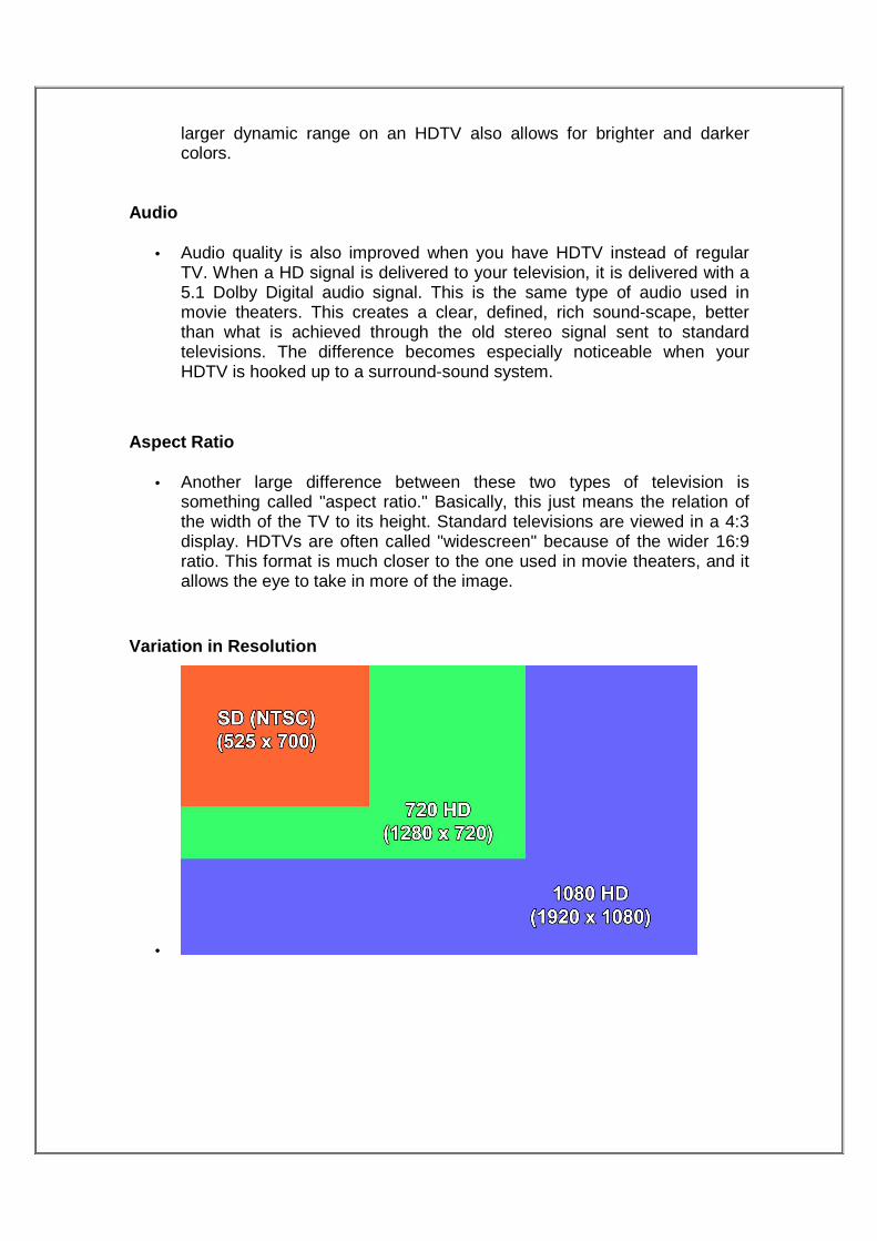
Variation in Resolution
•

Comparison Chart
differences between standards are summarized below:
SDTV HDTV HDTV HDTV
Width/Scan 480i 720p 1080i 1080p
Resolution 640x480 1280x720 1920x1080 1920x1080
Ratio 4:3 16:9 16:9 16:9
MERITS AND DEMERITS Merits of SDTV:
• SDTV is more vivid than analog TV because it has less noise.
• It has better sound.
• SDTV have many accompanying functions. For example, multitasking,
electronic program guide, and so on. These functions are impossible at
analog TV.
Demerits of SDTV:
• Compared to HDTV, it has lower resolution.
Merits of HDTV:
• HDTV has twice the linear resolution of standard-definition television
(SDTV), thus showing greater detail than either analog television or
regular DVD.
• Effective image resolution is increased.
Demerits of HDTV:
• A very high resolution source may require more bandwidth than available
in order to be transmitted without loss of fidelity.
• The lossy compression that is used in all digital HDTV storage and
transmission systems will distort the received picture, when compared to
the uncompressed source.
Implementation of HDTV
The HDTV production chain typically begins with a high-definition camera, or a project shot on film then converted to a digital format. However other means are possible. Much of Tim Burton’s recent stop-motion feature, The Corpse Bride was shot with a Canon digital still camera, and then transferred to digital video for editing. Many commercials, cartoons, and full-length features have been created solely with 2D and/or 3D animation software. RESOLUTION: As mentioned the TV screen is made of lines. More the Number of lines, better the detail. The conventional TV has 625 lines. When the HDTV was introduced it had 1250 (HD-MAC) lines which provided sufficiently high resolution as compared to film. Presently (and when I say presently it means the DIGITAL era when the things change while you write about them), there are various standards. Among them the most talked about are with 780 lines and 1080 lines. We can not go in detail as it would add so many complicated technical terms. It can be summarized that on the front of resolution too the TV is becoming a match for the films. CONTRAST: This is tricky to discuss. Just visit a high tech shop and look At the latest Plasma after reducing the colours to zero. Compare it with your old black and white photographs. You can get your answer. FLICKER : It can be safely said that this problem has been almost Completely tackled with. In modern display devices whether plasma or LCD, flicker is virtually absent.