Report on Doordarshan indore
42
Oriental university, Indore 2014-15 Department of Electronics and Communication Page 1 CHAPTER-1 INTRODUCTION TO DOORDARSHAN 1.1 INTRODUCTION TYPE Broadcast television network. COUNTRY India. AVAILABILITY National. OWNER Prasar Bharati. LAUNCH DATE 1959. PAST NAME All India Radio. WEBSITE http://www.ddindia.gov.in Doordarshan is a public broadcast terrestrial television channel run by Prasar Bharati ,a board nominated by the Government of india.it is one of the largest broadcasting organization in this world in terms of the infrastructure of studios and transmitters recently it has also started terrestrial transmitters. Beginning Doordarshan had a modest beginning with the experimental telecast stating in Delhi in September 1959 with a small transmitter and a make shift studio. The regular daily transmission started in 1965 as a part of all India radio. The television service was extended to Mumbai (then Bombay) and Amritsar in 1972 tills 1975 seven India cities had television service and Doordarshan remained the only television channel in India. Television services were separated from radio in 1976.Each office of All India Radio and Doordarshan were placed under the management of two separate director generals in New Delhi. Finally Doordarshan as a national Broadcaster came in to existence.
-
Upload
abhishek-roy -
Category
Engineering
-
view
221 -
download
2
Transcript of Report on Doordarshan indore
Oriental university, Indore 2014-15
Department of Electronics and Communication Page 1
CHAPTER-1
INTRODUCTION TO DOORDARSHAN
1.1 INTRODUCTION
TYPE Broadcast television network.
COUNTRY India.
AVAILABILITY National.
OWNER Prasar Bharati.
LAUNCH DATE 1959.
PAST NAME All India Radio.
WEBSITE http://www.ddindia.gov.in
Doordarshan is a public broadcast terrestrial television channel run by Prasar Bharati ,a board
nominated by the Government of india.it is one of the largest broadcasting organization in this
world in terms of the infrastructure of studios and transmitters recently it has also started terrestrial
transmitters.
Beginning
Doordarshan had a modest beginning with the experimental telecast stating in Delhi in September
1959 with a small transmitter and a make shift studio. The regular daily transmission started in
1965 as a part of all India radio. The television service was extended to Mumbai (then Bombay)
and Amritsar in 1972 tills 1975 seven India cities had television service and Doordarshan remained
the only television channel in India. Television services were separated from radio in 1976.Each
office of All India Radio and Doordarshan were placed under the management of two separate
director generals in New Delhi. Finally Doordarshan as a national Broadcaster came in to
existence.

Oriental university, Indore 2014-15
Department of Electronics and Communication Page 2
Doordarshan Indore has up linking frequency 6174.5MHZ and down linking frequency
3949.5MHZ.The location of INSAT-3A is 93.5° east.
1.2 SATELLITE UPLINKING AND DOWNLINKING FREQUENCIES
TABLE-1.1
BANDS DOWNLOAD FREQ(GHz) UPLINK FREQ (GHz)
S 2.555 to 2.635 5.855 to 5.935
C(Lower) 3.4 to 3.7 5.725 to 5.925
C(Upper) 4.5 to 4.8 6.425 to 7.075
KU 10.7 to 13.25 12.75 to 14.25
KA 18.3 to 22.20 27.0 to 31.00
1.3 TERRESTRIAL TELEVISION
BAND-(I) (40 to 68MHZ)
TABLE-1.2
CHANNEL RANGE VISION FREQ. AURAL FREQ.
1 ` 41.25 46.75
2 47-54 48.25 53.75
3 54-61 55.25 60.75
4 61-68 62.25 67.75
BAND-(II) 88MHZ to 108MH (FOR FM)
108MHZ to 174MHZ (Other Telecommunication)
BAND-(III) T.V TRANSMITTION.(174MHZ to 230MHZ)
Oriental university, Indore 2014-15
Department of Electronics and Communication Page 3
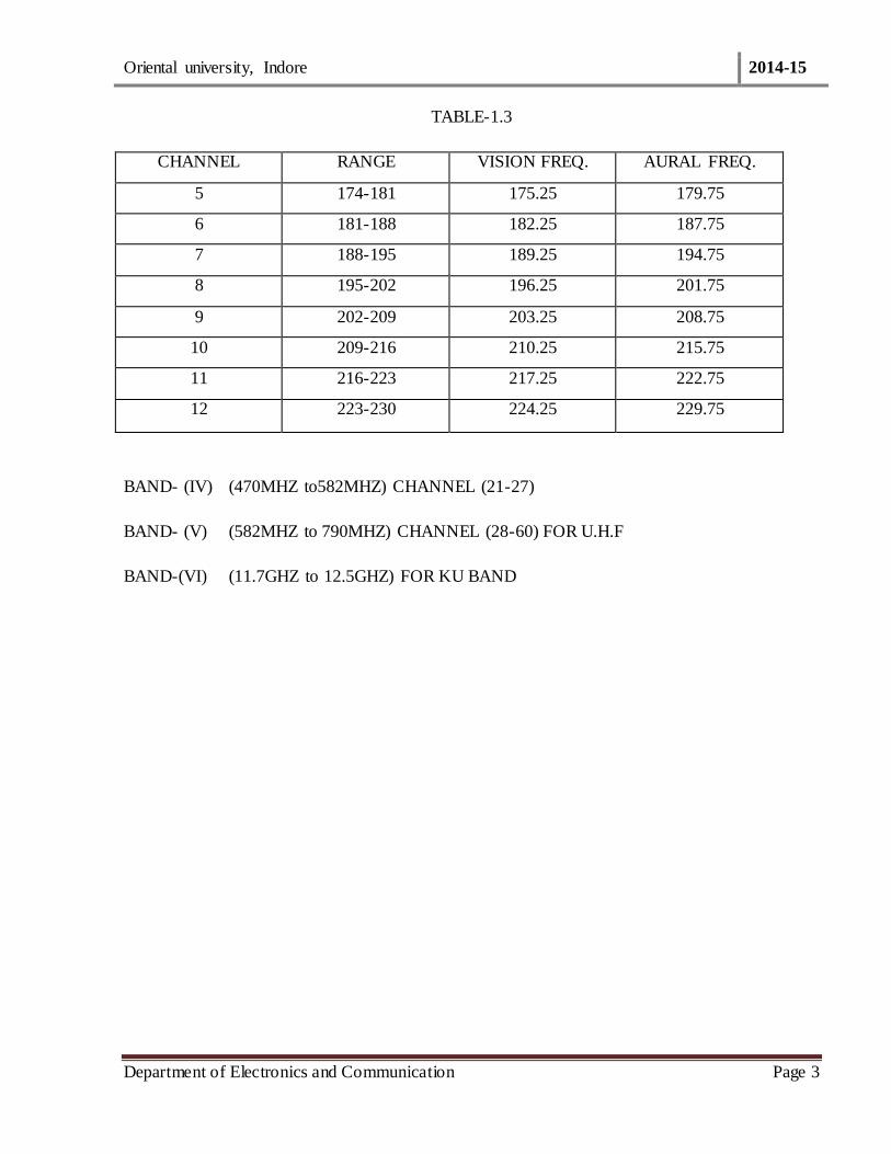
TABLE-1.3
CHANNEL RANGE VISION FREQ. AURAL FREQ.
5 174-181 175.25 179.75
6 181-188 182.25 187.75
7 188-195 189.25 194.75
8 195-202 196.25 201.75
9 202-209 203.25 208.75
10 209-216 210.25 215.75
11 216-223 217.25 222.75
12 223-230 224.25 229.75
BAND- (IV) (470MHZ to582MHZ) CHANNEL (21-27)
BAND- (V) (582MHZ to 790MHZ) CHANNEL (28-60) FOR U.H.F
BAND-(VI) (11.7GHZ to 12.5GHZ) FOR KU BAND

Oriental university, Indore 2014-15
Department of Electronics and Communication Page 4
CHAPTER-2
FUNDAMENTAL OF MONOCROME AND COLOR TV SYSTEM
2.1 PICTURE FORMATION
A picture can be considered to a number of small elementary areas of light or shade which are
called PICTURRE ELEMENTS. The thus contain the visual image of scene.
In the case of TV camera the scene is focused on the photosensitive surface of pick up device and a
optical image is formed. The photoelectric properties of pick up device convert the optical image
to electric charge image depending on the light and shade of the scene(picture elements).Now it is
necessary to pick up this information and transmit it. For this purpose scanning is employed.
Electron beam scans the image line by line and field to provide signal variation s in a successive
order.
The scanning is both in horizontal and vertical direction simultaneously.
The horizontal scanning frequency is 15,625 Hertz.
The vertical scanning frequency is 50 Hz.
The frame is divided into two fields. Odd lines are scanned first and then the even lines. The odd
and even lined are interlaced. Since the frame is divided into 2 fields the flicker reduces the field
rate is 50 Hertz. The frame rate is 25 Hertz (Field rate is the same as power supply frequency).
2.2 NUMBER OF TV LINES PER FRAME
If the number of TV lines is high larger bandwidth of video and hence larger R.F. channel width is
required. If we go for larger RF channel width the number of channel in the R.F. spectrum will be
reduce. However with more number of TV lines on the screen the clarity of the picture i.e.
resolution of improves. With lesser number of TV lines per frame the clarity (quality) is poor.
The capability of the system to resolve maximum no. Of picture elements along scanning linens
determines the horizontal resolution. It means how many alternate black and white elements
Oriental university, Indore 2014-15
Department of Electronics and Communication Page 5
can be there in a line. Let us also take another factor. It is realistic to aim at equal vertical
black and white dots on line can be 575x0.69x4/3 which is equal to 528.
It means there are 528 divided by 2 cyclic changes i.e. 264 cycles. There 264 cycles are there
during 52 micro seconds. Here the highest frequency is 5MHz
Highest =264x10⁶/52= 5MHz
Therefore the horizontal resolution of the system is MHz A similar calculation for 525 linens
system limits the highest a frequency to 4 MHz and hence the horizontal resolutions of same value.
In view of the above the horizontal bandwidth of signal in 625 lines system is 5 MHz
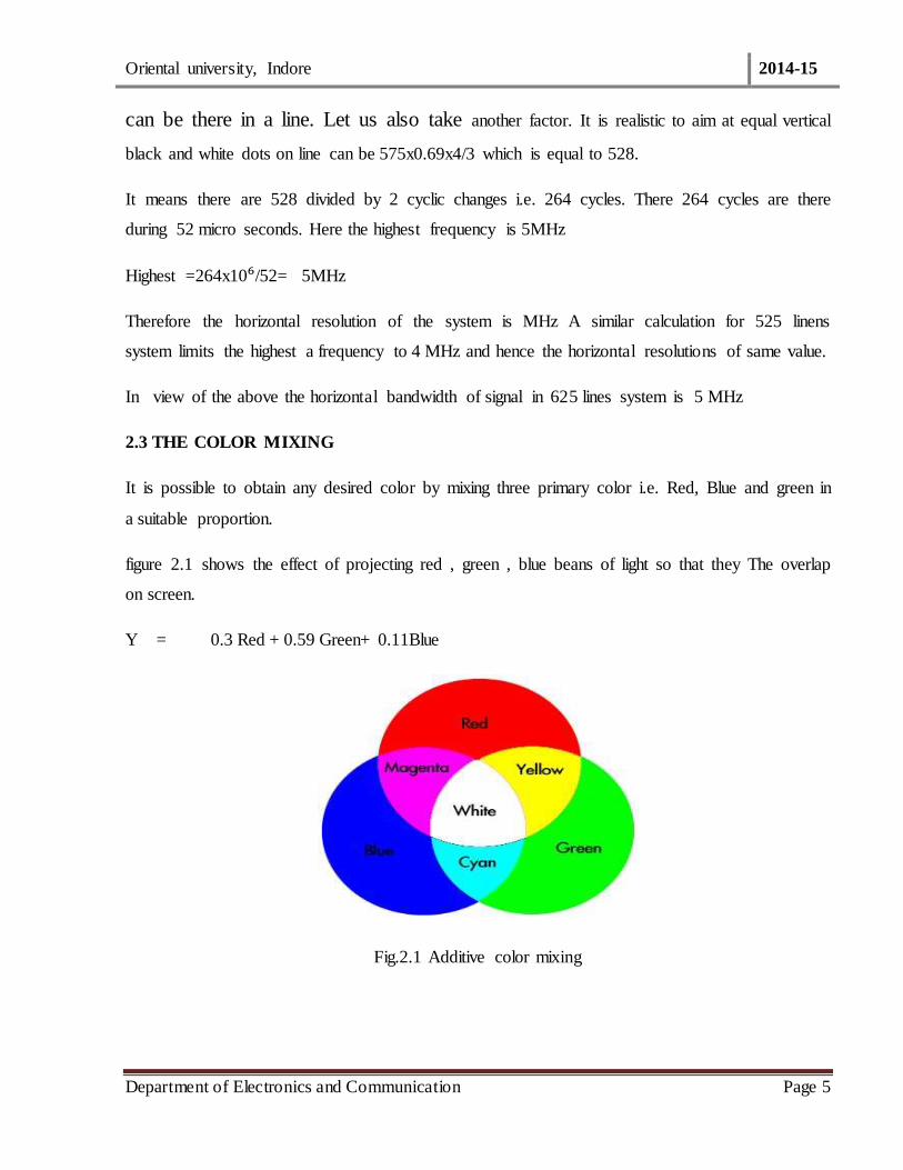
2.3 THE COLOR MIXING
It is possible to obtain any desired color by mixing three primary color i.e. Red, Blue and green in
a suitable proportion.
figure 2.1 shows the effect of projecting red , green , blue beans of light so that they The overlap
on screen.
Y = 0.3 Red + 0.59 Green+ 0.11Blue
Fig.2.1 Additive color mixing
Oriental university, Indore 2014-15
Department of Electronics and Communication Page 6
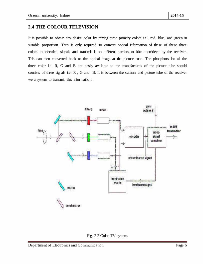
2.4 THE COLOUR TELEVISION
It is possible to obtain any desire color by mixing three primary colors i.e., red, blue, and green in
suitable proportion. Thus it only required to convert optical information of these of these three
colors to electrical signals and transmit it on different carriers to bbe deco\deed by the receiver.
This can then converted back to the optical image at the picture tube. The phosphors for all the
three color i.e. R, G and B are easily available to the manufactures of the picture tube should
consists of three signals i.e. R , G and B. It is between the camera and picture tube of the receiver
we a system to transmit this information.
Fig. 2.2 Color TV system.
Oriental university, Indore 2014-15
Department of Electronics and Communication Page 7
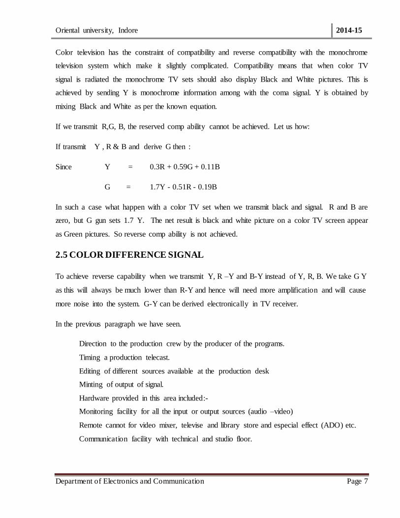
Color television has the constraint of compatibility and reverse compatibility with the monochrome
television system which make it slightly complicated. Compatibility means that when color TV
signal is radiated the monochrome TV sets should also display Black and White pictures. This is
achieved by sending Y is monochrome information among with the coma signal. Y is obtained by
mixing Black and White as per the known equation.
If we transmit R,G, B, the reserved comp ability cannot be achieved. Let us how:
If transmit Y , R & B and derive G then :
Since Y = 0.3R + 0.59G + 0.11B
G = 1.7Y - 0.51R - 0.19B
In such a case what happen with a color TV set when we transmit black and signal. R and B are
zero, but G gun sets 1.7 Y. The net result is black and white picture on a color TV screen appear
as Green pictures. So reverse comp ability is not achieved.
2.5 COLOR DIFFERENCE SIGNAL
To achieve reverse capability when we transmit Y, R –Y and B-Y instead of Y, R, B. We take G Y
as this will always be much lower than R-Y and hence will need more amplification and will cause
more noise into the system. G-Y can be derived electronically in TV receiver.
In the previous paragraph we have seen.
Direction to the production crew by the producer of the programs.
Timing a production telecast.
Editing of different sources available at the production desk
Minting of output of signal.
Hardware provided in this area included:-
Monitoring facility for all the input or output sources (audio –video)
Remote cannot for video mixer, televise and library store and especial effect (ADO) etc.
Communication facility with technical and studio floor.
Oriental university, Indore 2014-15
Department of Electronics and Communication Page 8
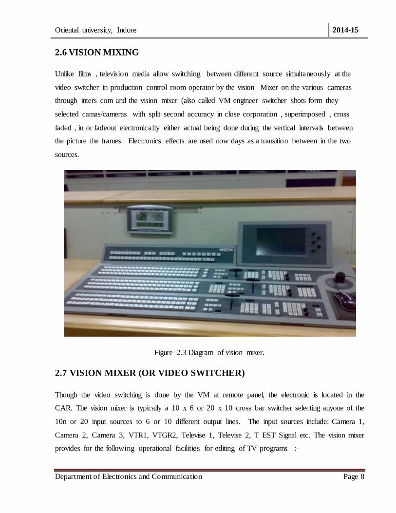
2.6 VISION MIXING
Unlike films , television media allow switching between different source simultaneously at the
video switcher in production control room operator by the vision Mixer on the various cameras
through inters com and the vision mixer (also called VM engineer switcher shots form they
selected camas/cameras with split second accuracy in close corporation , superimposed , cross
faded , in or fadeout electronically either actual being done during the vertical intervals between
the picture the frames. Electronics effects are used now days as a transition between in the two
sources.
Figure 2.3 Diagram of vision mixer.
2.7 VISION MIXER (OR VIDEO SWITCHER)
Though the video switching is done by the VM at remote panel, the electronic is located in the
CAR. The vision mixer is typically a 10 x 6 or 20 x 10 cross bar switcher selecting anyone of the
10n or 20 input sources to 6 or 10 different output lines. The input sources include: Camera 1,
Camera 2, Camera 3, VTR1, VTGR2, Televise 1, Televise 2, T EST Signal etc. The vision mixer
provides for the following operational facilities for editing of TV programs :-
Oriental university, Indore 2014-15
Department of Electronics and Communication Page 9
Thus, color difference signals fulfill the compatibility and reverse capability . Because in this case
the color difference signals are zero if the original signal is monochrome (i.e. . R = B = G)
So if we take R –Y =R – (0.3R + 0.59R + 0.11R) = 0
Similarly B –Y = 0
As such color difference signals are zero for white or any shade of gray where ,Y carries the entire
Luminance information.
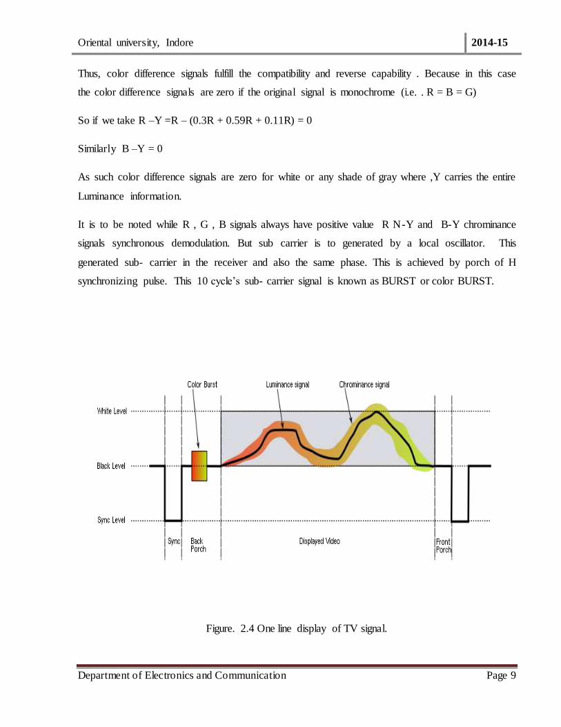
It is to be noted while R , G , B signals always have positive value R N-Y and B-Y chrominance
signals synchronous demodulation. But sub carrier is to generated by a local oscillator. This
generated sub- carrier in the receiver and also the same phase. This is achieved by porch of H
synchronizing pulse. This 10 cycle’s sub- carrier signal is known as BURST or color BURST.
Figure. 2.4 One line display of TV signal.

Oriental university, Indore 2014-15
Department of Electronics and Communication Page 10
2.8 PAL ENCODER
Figure. 2.5 Block diagram of PAL Encoder.
Oriental university, Indore 2014-15
Department of Electronics and Communication Page 11
CHAPTER-3
VIDEO CHAIN IN A TYPICAL DOORDARSHAN STUDIO
3.1 STUDIO CENTRE
A Studio Centre of Doordashan has the following objectives:-
To originate program from studio for live telecast or for recording originated video tape.
To knit various coerces of program available at the production camera output videos , feed
from others films , videos and characters of especial studios.
Procession transitions alert series of various destination of channel.
Routing of switching room and micro watching transmitter or any other desired destination.
3.1.1 ACTIVITIES IN A TELEVISION STUDIO CAN BE DIVIDED INTO THREE
MAJOR AREA SUCH AS
Action area
Production Control room , and
Central apparatus room.
This palace required large space and ceiling as compared to any other technical area. Action in
thus area included staging, lighting, performance by artiest, and arrangement to pick up picture and
sound. Hardware required for these activities in a studio (typical size 20 x 20 x8.5 cubic meters.)
are:-
Very efficient air controlling because a lot of heat dissipation by studio light and presence of large
number of persons invited audience performing artists and operational crew.
Uniform and even flooring for smooth operation of camera dollies and boom microphones etc.

Oriental university, Indore 2014-15
Department of Electronics and Communication Page 12
3.1.1.1 ACTION AREA
Acoustic treatment keeping in mind that a television studio is a multi-purpose studio with a lot of
moving persons and equipment during a production.
Supporting facilities like properties wardrobes and makeup etc.
Effective communication facilities for the crew with the production control area.
Studio camera (three to four) one of the cameras fitted with the telecast system and
pressure dolly.
Luminary and suspension
Pick up wall sockets for audio operations.
Tie lines box for video and audio lines from control of room.
Cyclorama and curtain tracks for blue and black curtain for chrome keying and
limboillghtine respectively.
Audio and video monitoring facilities
Studio warning light and safety devices like fire alarm system and firefighting
equipment’s etc.
Digital clock display.
Operational requirement from the technical crew may vary from programme. These requirements
for lighting , audio pick up and special effects etc. depends upon he programme requirement such
as establishing a period , time, formal or informal or informal situation.
3.1.1.2 PRODUCTION CONTROL AREA
Activities in this area are
Take: Selection of any input source
Or
Cut: Switching clearly from one source to another.
Dissolve: Fading out of one source of video and fading in another source of video.

Oriental university, Indore 2014-15
Department of Electronics and Communication Page 13
Superposition of Two sources Keyed caption when selected inlays superimposed on the
background picture.
Special Effects A Choice of a number of a number of wipe patterns for slip screen on wipe effects.
The selected output can be moment in the crooning preview monitors. The picture element are
available on the monitors, VT test signals etc with any desire special effect, prior to its switching.
The switcher also provides cue facilities to switch camera tally light as an indication to the
cameraman whether his camera is on output of the switcher.
Present day PCR’s have:-
24 input video special effects switchers
(CD 680 or CD 682-SP)
Character generators
Telecom/ DLS remote controls
Adequate monitoring equipment.
3.1.2 CHARACTER GENERATOR (CG)
Character Generator provides titles and credit captions during production in Roman script. It
provides high resolution characters, different color for colorizing characters, background, edge etc.
At present bilingual band triangular C.G are also being used by Doordarshan.
Character Generators is a microcomputer with Text along instructions when typed in at the
keyboard is stored on a floppy or hard disk. Many page of scripts can be stored on hard disk and
recalled when needed by typing the address for the stored page , to appear as one of the video
sources.
3.1.3 SYNC PULSE GENERATOR (SPG)
It is essential that all video sources as input to the switcher are in synchs are stars all the frames of
video sources is conductor. It consist of highly stable camera from this crystal oscillation vacuum
pulse of stand width and frequency are derived from the crystal electronically which from clock
for generation of video signal. These pulses this objective of synchronism. Because of its
importance, SPG is normally duplicate for change over cases of failure.

Oriental university, Indore 2014-15
Department of Electronics and Communication Page 14
It provides the following output:
1) Line drive.
2) Field drive.
3) Mixed blanking.
4) Mixed sync.
5) Color sub –carrier.
6) A burst insertion pulse.
3.2 PAL PHASE INDENT PULSES
3.2.1 CAMERA CONTROL UNIT (CCU)
The television cameras which include camera head with its optical focusing lens, pan and tilt head ,
video signal pre –amplifier view finder and other associated electronic circuitry are mounted on
cameras trolley and operate inside the studios. The output of camera is pre –amplifier in the head
and then connected to the camera control unit (CCU) through long multi – core cable (35 to 40
cores) , or triad cable.
All the camera control voltages are fed from the CCU to the camera head over the multi-core
camera cable. The view –finder signal is also sent over the camera cable to the camera head
view- finder for helping the camera in proper focusing, adjusting composing the shots.
The video signal obtain is amplifier the corrected, equalized for cable decays , D C clamped
horizontal and vertical blanking pulses added to it the peak white levee is also clipped a video
overloading on the following stage and avoiding over modulation in the transistor. The composite
sync signals are then added and these video signal are fed to a distribution amplifier , which
normally give multiple outputs for monitoring etc.

Oriental university, Indore 2014-15
Department of Electronics and Communication Page 15
Figure . 3.1 Diagram of CCU.
3.2.2 LIGHT CONTROL
The scene to be telecasted most be well laminated to produce a clear and noise free picture. The
lighting should give the depth , the correct contrast and artistic display various shade without
multi shadows .
The lighting arrangement I a TV studio have to be very elaborated. A large number of lights to
used meet the needs of ‘key’, ‘fill’, and ‘back’ light etc. Lights are classified as spot and soft lights.
These are suspended from motorized hoists and telescopes. The up and down movement is
remotely controlled. The switching on and off lights at the required time and diming is controlled
from the light controlled panel in siding a lighting control room using SCR dimmer controls .
Type remotely control various lights are inside the studios.
3.2.3 SOUND MIXING
As a rule in Television, sound accompanies the picture. Several microphones are generally
required for production of complex television program beside the other audio sources in the
synchronization with the level of sound sometimes is varied in accidence with the shot
composition called “Prospective ".
3.2.4 AUDIO FACILITIES
An audio mixing console with a number say about 32 inputs is provided in major studio. This
include specter facilities such as equalization PFL , phased reverberation chosen / receive and

Oriental university, Indore 2014-15
Department of Electronics and Communication Page 16
digital reverberation units at some places tape recorders and FM 98 disrupt[roved playing back/
creating audio effects important sources (married) to the switcher.
3.2.5 VIDEO TAPE RECORDER
VTR room is provided at studio center. It houses is few broadcast standard videocassettes (VCRs).
In these recorders, sound and video signals are recorded simultaneously on the same tape.
Most of the TV center have professional quality B-Format BCN-51 inch VTRs. For broadcast
quality play back it is required with correction electronics i.e. a processer which comprise velocity
error compensation, drop- out compensation and time based correction. It also comprises a digital
variable motion unit enabling still reproduction, slow motion and visible search operation.
New centers are being supplied with Sony U-mastic high band VCRs along with ½” Beta cam SP
VCTs, DVC pro
Fig. 3.2 Diagram of Video tape recorder.
3.2.6 POST PRODUCTION SUITES
Modern videotape editing has revolutionized the production of television programs over years. The
latest tend all over the world is to have more of fully equipped post production suites than number
of studios. Most of present day shooting are done on location using single camera. The actual
production is done in tease suites. The job for post-production suits is: -

Oriental university, Indore 2014-15
Department of Electronics and Communication Page 17
To knit program available on various sources..
While doing editing with multiple sources it should be possible to have any kind of
transition.
Adding / mixing sound tracks.
Voice over facilities.
Creating spectra effects.
The concept of live editing of sound mixer is replaced by “to do it at post production suites’.
Well-equipped post production suites with have : -
Five VTRs/VCRs may be different format remotely controlled by the editor.
Visi0n mixing with especial effect and wipes of with control from remote editor panel .
Apex Digital Optics (ADO) for special effects.
Audio mixer with remote control from the editor remote panel.
Multi – track audio recorder with time code facilities and remote operation.
Character generator for titles.
Adequate monitoring facilities.
Supported by “offline editing system” to save time in post-production
suite.
One man operation.
3.2.7 COVERAGE OF OUTSIDE EVENTS
Outside broadcasters (OBs) provide an important part of the television programs. Major events
like Spots , important functions , and performance are covered with an O.B van which contain all
the essential facilities.
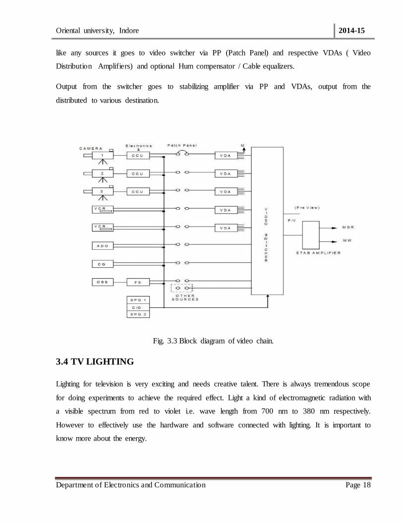
3.3 VIDEO CHAIN
The block diagram of facing page contains all these section and it can be observed that the CAR
is the nodal data. Now let us follow the CAM – signal. CAM –I first goes to a camera electronics
in CAR via a multi core cable, the signal is then matched / adjusted for quality in CCU and then
Oriental university, Indore 2014-15
Department of Electronics and Communication Page 18
like any sources it goes to video switcher via PP (Patch Panel) and respective VDAs ( Video
Distribution Amplifiers) and optional Hum compensator / Cable equalizers.
Output from the switcher goes to stabilizing amplifier via PP and VDAs, output from the
distributed to various destination.
Fig. 3.3 Block diagram of video chain.
3.4 TV LIGHTING
Lighting for television is very exciting and needs creative talent. There is always tremendous scope
for doing experiments to achieve the required effect. Light a kind of electromagnetic radiation with
a visible spectrum from red to violet i.e. wave length from 700 nm to 380 nm respectively.
However to effectively use the hardware and software connected with lighting. It is important to
know more about the energy.
Oriental university, Indore 2014-15
Department of Electronics and Communication Page 19
3.5 LIGHT SOURCE
Any light source has luminance energy which measured in Candelas. Candela is equivalent an
intensity created by standard one candid source of light.
BASIC THREE POINT LIGHTING
Key light - This is the principal light source of illumination it give shape and modeling by
casting shadows. It is tartest like sum of the sky and it should cast only is a one showdown.
Normally it the hand spectrum.
Fill Light - Controls the lighting contrast by filling in shadows. It can also provide catch
light in the eyes. Normally it soft source.
Back Light - Separated the body from the background, roundness to the subject and reveals
texture. Normally it is hard source.
3.6 BACKGROUND LIGHT-Separate the person from the background, reveals background
interest and shade. Normally it is a hard source. In three point lighting the radio of 3/2/1
(Back/Key/Fill) for mono and 3/2/2 for color provide good portrait lighting.
3.7 TV CAMERA
INTRODUCTION
A TV CAMERA CONSISTS OF THREE SECTION
a) A Camera lens and optics : To from optical image on the face plate of a pickup device
b) A transducer or pick up device: To convert optical image into an electrical signal.
c) Electronic: To process output of a transducer to get a CCCVS signal.
3.7.1 CCD CAMERA
INTRODUCTION
Any camera will need a device to optical an electrical signal. Let us consider a picture or better
resolution small picture element. For more snappish or better resolution, we have to increase this
element. The picture arrange now be focused on to signature of so many CCD elements. Each
CCD element will now convert the light information to on it to charge signal. All need now to have
Oriental university, Indore 2014-15
Department of Electronics and Communication Page 20
an arrangement to collect this and convert to it voltage the basic principle on which CCD camera
are based.
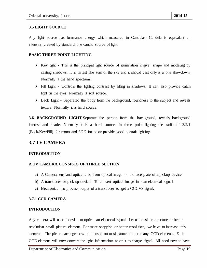
3.7.2 LATEST CCD CAMERA
CCD were launched in 1983 from broadcast with pixel count from a more 2,50,000 which
increased to 20,00,000 in 1994 for HHDTV application . Noise and aliasing has been reduced to
negligible level. CCD camera now offer fully modulated video output as light level as 6.0 lumens.
Atypical specification for a studio now available in something like 2/3 inch , Fit lens on chop CCD
with 6,00,000 pixel 850 Linea H resolution , Sensitivity F-8(2000 Lux) etc.
Fig. 3.4 CCD Camera.
Oriental university, Indore 2014-15
Department of Electronics and Communication Page 21
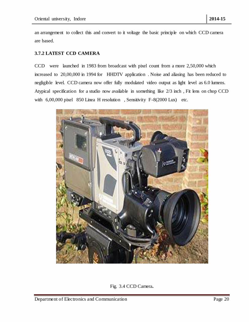
Fig.3.5 Block diagram of Typical Camera.
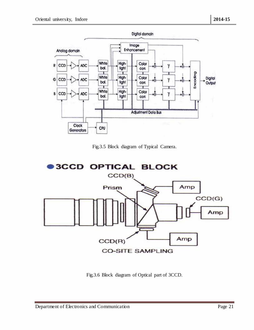
Fig.3.6 Block diagram of Optical part of 3CCD.
Oriental university, Indore 2014-15
Department of Electronics and Communication Page 22
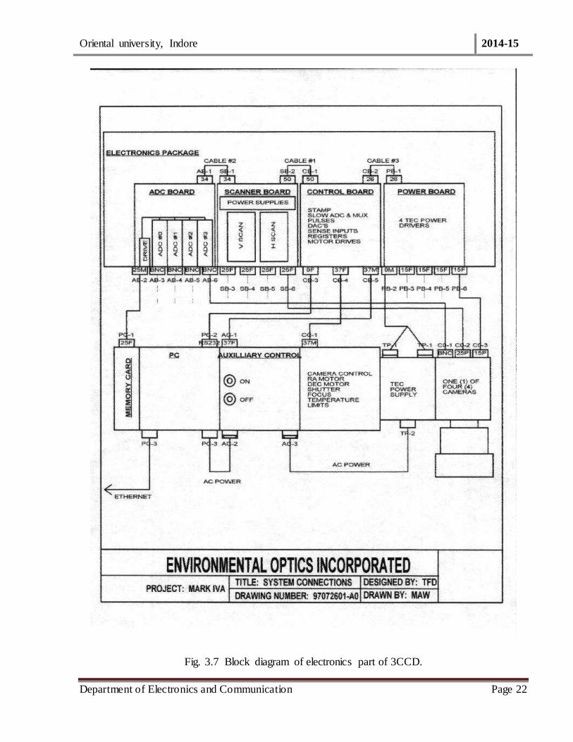
Fig. 3.7 Block diagram of electronics part of 3CCD.

Oriental university, Indore 2014-15
Department of Electronics and Communication Page 23
CHAPTER-4
HIGH POWER TV TRANSMITTER
4.1 DESIGN OF TRANSMITTER
All the TV transmitters have the same basic design. The of an exciter followed by power
amplifiers which boost the exciter power to the required level. In BEL mark transmitted three
valve stage 450 CX , BEL 4500 CX are seen vision transmitter chain and two BEL transmitter
50 aural transmitter chain in BEL make the transmitters only the wave stage ( BEL 4500 and
BEL - CX) and vision transmitter chain . Aural transmitter chain is fully solid stage in mark all
transmitter. But now a day’s use VHF TV Transmitter (NEC JAPAN).
4.1.1 PCN-1610SSPH/1VHF TV TRANSMITTER
It is a digital transmitter.
Its power rating is 10KW.
The main parts of the transmitter are :
(1) Exciter
(2) Amplifier.
Fig. 4.1 Block diagram of PCN-1610SSPH/1 VHF TV Transmitter.
Oriental university, Indore 2014-15
Department of Electronics and Communication Page 24
4.2 EXCITER
In exciter there are to separate inputs for video & audio signal.
The video signal is first applied to A/D - D/A.
Then the video signal is modulated with frequency 38.9MHZ in if Modulator (AM).
The output of IF modulator is then given to a mixer where it is mixed With a low
frequency of 249.15MHZ generated by a synthesizer.
The o/p of mixer (V) is amplitude modulated wave with frequency 210.25MHZ.
The o/p of mixer (A) frequency modulated wave with frequency 215.75MHZ.
Frequency of video signal 5 MHZ and that of the audio signal it is about 15 KHZ.
The audio signal is modulated in IF modulator with carrier frequency33.4 MHZ.
FM is done with audio signal, where as AM is done with video signal.
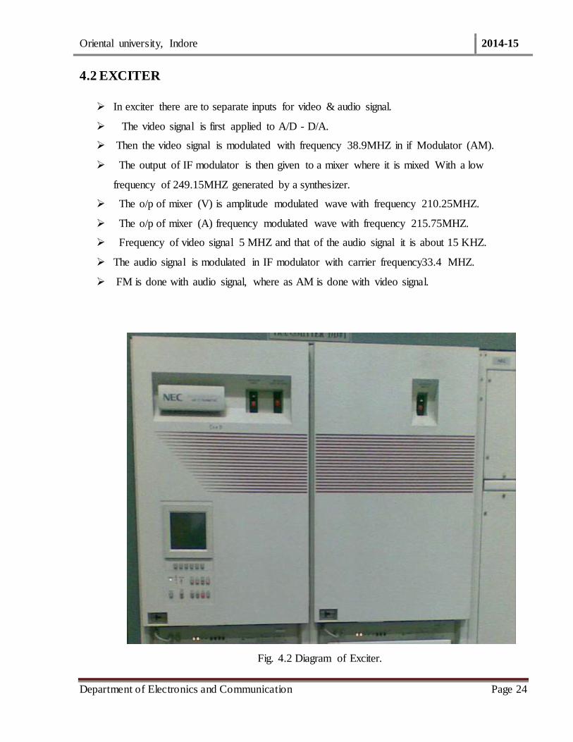
Fig. 4.2 Diagram of Exciter.
Oriental university, Indore 2014-15
Department of Electronics and Communication Page 25
4.3 AMPLIFIRE
The o/p of video & audio mixer are only of power approx. Equal to 15 dB
The modulated video (AM-VSB) signal amplified up to 10 KW by video amplifier.
The modulated audio (FM) signal is amplified up to 1 KW by audio Amplifier.
The video amplifier consists of 10 power amplifier of 1 KW each.
The audio amplifier consists of 2 power amplifier of 1 KW each.
The amplified video & audio waves are then given to a DIPLEXER ,it accept the
modulated and amplified video and audio signal and mix them to generate a signal with a
frequency width of 7 MHZ in IF region.
The signal at the o/p of the diplexer is carried through coaxial pipe to the antenna which
transmits the information in the form of electromagnetic wave of a fixed frequency range in
to the space (air).
The reception of the information is done by Receiver tuned to the above Frequency range.
Here the wave is demodulated and information is recovered as it was prior to modulation.
The reception unit may be a home TV set.
The PCN-1610SSPH/1 VHF TV Transmitter is used for terrestrial Transmission. it is used
for transmission of DD1 on channel 10 at DDK INDORE.
A 1 KW transmitter is also used at DDK INDORE for the transmission of DD News on
channel 12 at DDK INDORE.
Each channel has a fixed operating frequency range.
The channel width is 7 MHZ.
Frequency of channel 10 is 210.25 MHZ for video & 215.75 MHZ for audio
There is difference of frequency 5.5MHZ between audio & video signal in each channel.
The frequency of channel 12 is 224.25MHZ for video and 229.75 MHZ For audio.
4.4 SOLID STAGE POWER AMPLIFIERS
Has got two identical sections. Each capable of delivering 10.
Get x28 V power supply through relay in 80 W AMP.
Sample of output is available at front panel for RF monitoring.
Provides A DC output corresponding to sync peak output for vision monitoring unit.
Oriental university, Indore 2014-15
Department of Electronics and Communication Page 26
Thermostat on heat sink connected in series with thermostat or 80 W AMP and provide
thermal protection.( operating temp. 70 c).
4.5 TRANSMITTER SECTION
Its section is situated at KANKARBAGH. It main work function is to provided TV signal
transmitted to a range of 7KM.DDK, Silchar transmitter is 150m.for transmitting the signal, first
of all receive, the signal of satellite. This transmitted signal is catches by TV receiver and to see
the program.
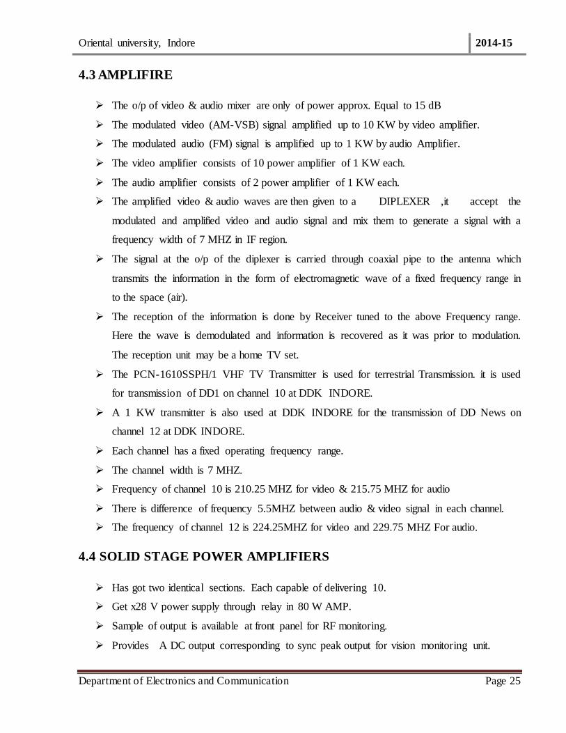
Fig.4.4 Block diagram Transmitter.

Oriental university, Indore 2014-15
Department of Electronics and Communication Page 27
4.6 TRANSMITTER CONTROL SYSTEM
The transmitter control unit performs the task of transmitter interlocking and control. Also it
supports operation from control console. The XTR control unit (TCU) has two depended system
viz.
1. Main Control System (MCS)
2. Back –up Control System
4.6.1 SYSTEM DESCRIPTION OF EXITER
4.6.1.1 VIDEO CHAIN-The signal is fed to a video processor. In VHF transmitter, equalizer and
receiver pre –corrected, pre0 rerecorded video processor.
4.6.1.2LOW PASS FILTER-Filter has limit in combine video signal to 5 MHz
4.6.1.3 RECEIVER PRE – CORRECTOR
Pre- distorts the signal providing partial compensation o GD which occurs in domestic receivers.
Both the delay equalizer and receiver pre-recorded are combined in delay equalizer module in
mark III vision.
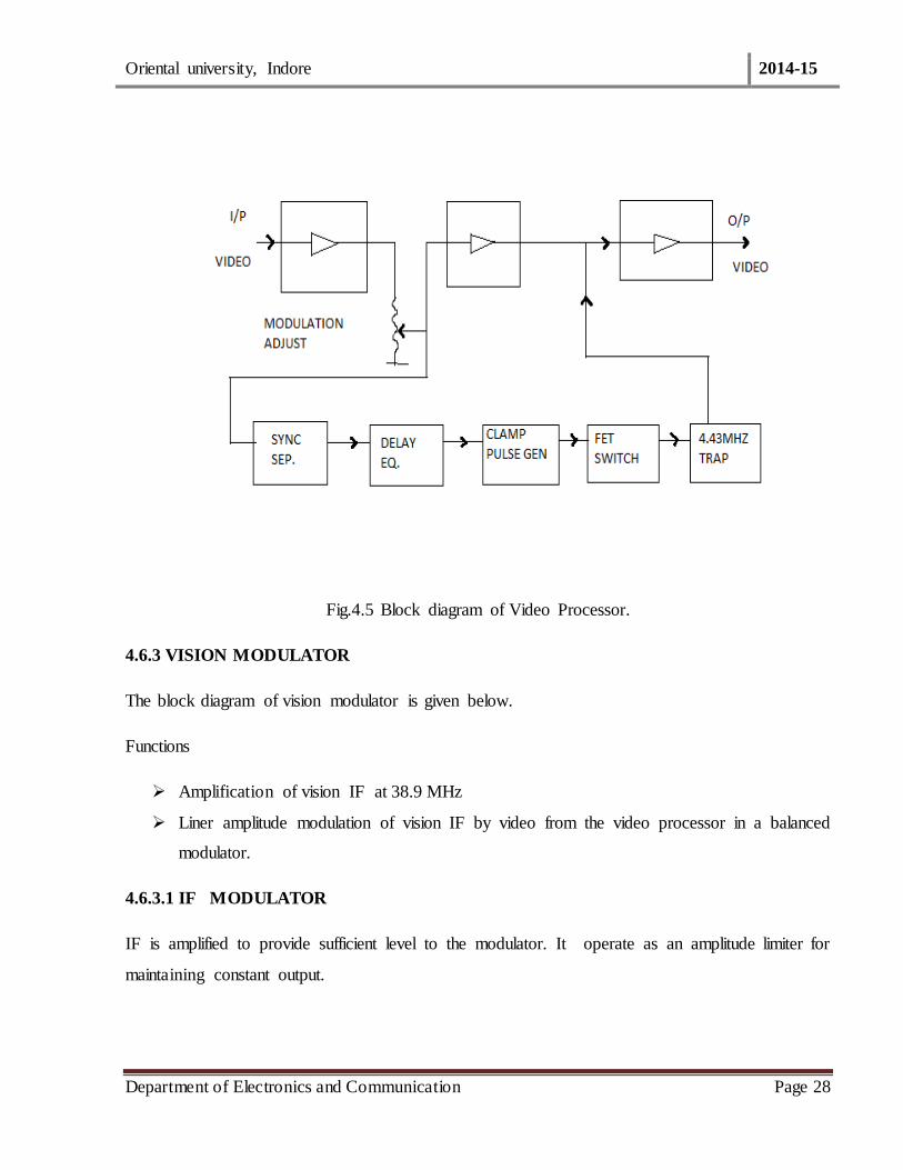
4.6.2 VIDEO PROCESSOR
The block diagram of video processor is given below.
Functions
Amplification of video signal
Clamping at back porch of video signal.
Clamping give contrast peak power. Zero volt reference line is steady irrespective of video signal
pattern when clamping takes place otherwise the base line starts an excursion about the zero
reference depending on the video signal.
Oriental university, Indore 2014-15
Department of Electronics and Communication Page 28
Fig.4.5 Block diagram of Video Processor.
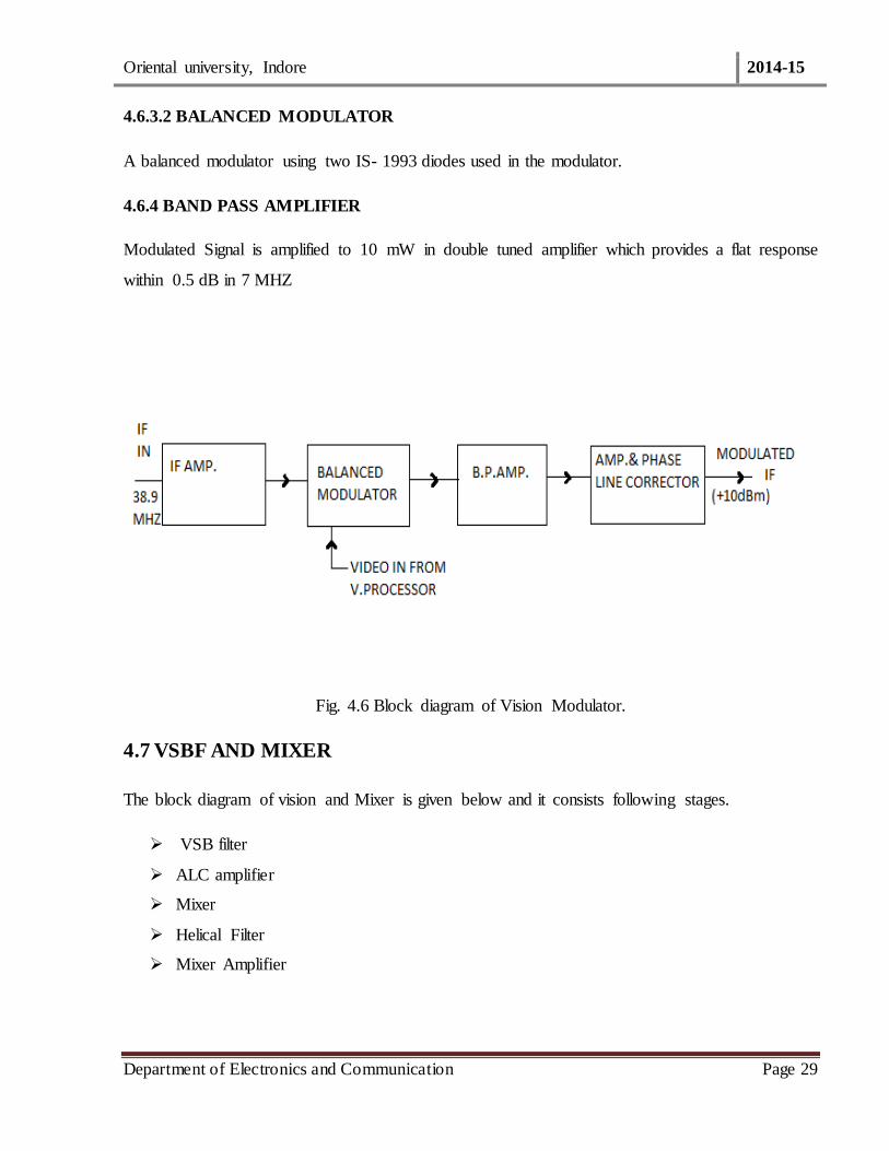
4.6.3 VISION MODULATOR
The block diagram of vision modulator is given below.
Functions
Amplification of vision IF at 38.9 MHz
Liner amplitude modulation of vision IF by video from the video processor in a balanced
modulator.
4.6.3.1 IF MODULATOR
IF is amplified to provide sufficient level to the modulator. It operate as an amplitude limiter for
maintaining constant output.
Oriental university, Indore 2014-15
Department of Electronics and Communication Page 29
4.6.3.2 BALANCED MODULATOR
A balanced modulator using two IS- 1993 diodes used in the modulator.
4.6.4 BAND PASS AMPLIFIER
Modulated Signal is amplified to 10 mW in double tuned amplifier which provides a flat response
within 0.5 dB in 7 MHZ
Fig. 4.6 Block diagram of Vision Modulator.
4.7 VSBF AND MIXER
The block diagram of vision and Mixer is given below and it consists following stages.
VSB filter
ALC amplifier
Mixer
Helical Filter
Mixer Amplifier

Oriental university, Indore 2014-15
Department of Electronics and Communication Page 30
Fig. 4.7 Block diagram of VSBF Mixer.
4.7.1 VSB FILTER
Surface ACOUSTIIC wave (SAW) provide a very steep side band response with high attenuation
outside designated channel. It has a liner phase characteristic with a low amplitude and group delay
ripple.
4.7.2 LOCAL OSCILLATOR
The block of Local Oscillator is given in fig 4.8 .It supplies three equal outputs of +8 dBM at a
frequency of fv + fvif. This unit has 3 sub units.
(1) Fc/4 Oscillator - Generates frequency which is ¼ of desired channel frequency. Fine
freq. control is done by VC1.
(2) LO Mixer/Power divider - Here the above fc/4 frequency is multiplied by four to obtain
channel frequency of fc and them mixer with five. Power divided is also incorporated
to provide three isolated outputs equal level.

Oriental university, Indore 2014-15
Department of Electronics and Communication Page 31
Fig. 4.8 Block diagram of Local Oscillator
4.8 AUDIO CHAIN
4.8.1 AURAL MODULATOR
The aura l modulator unit consists of audio amplifier, VCR, Mixer and APC.
The block diagram of Aural of modulator is given below.
Fig. 4.9 Block diagram of Aural Modulator.
Oriental university, Indore 2014-15
Department of Electronics and Communication Page 32
4.9 AUDIO AMPLIFIER
A balanced audio signal at + dB from studio is converted to unbalance signal by audio transformer
T4. The output of this is taken through potentiometer to the input of Hybrid Audio Amp BMC
1003. A 50 micro second pre-emphasis is also provided.
VCO
This is vector tuned oscillator; its frequency can be varied by coil L4. Transistor TR-17 from the
oscillator. VCO output level is 0 dB
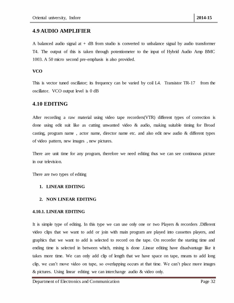
4.10 EDITING
After recording a raw material using video tape recorders(VTR) different types of correction is
done using edit suit like as cutting unwanted video & audio, making suitable timing for Broad
casting, program name , actor name, director name etc. and also edit new audio & different types
of video pattern, new images , new pictures.
There are unit time for any program, therefore we need editing thus we can see continuous picture
in our television.
There are two types of editing
1. LINEAR EDITING
2. NON LINEAR EDITING
4.10.1. LINEAR EDITING
It is simple type of editing. In this type we can use only one or two Players & recorders .Different
video clips that we want to add or join with main program are played into cassettes players, and
graphics that we want to add is selected to record on the tape. On recorder the starting time and
ending time is selected in between which, mixing is done .Linear editing have disadvantage like it
takes more time. We can only add clip of length that we have space on tape, means to add long
clip, we can’t move video on tape, so overlapping occurs at that time. We can’t place more images
& pictures. Using linear editing we can interchange audio & video only.
Oriental university, Indore 2014-15
Department of Electronics and Communication Page 33
Other problems with linear tape based editing are:
Editing in sequence-first shot first.
Long hours spent on rewinding of tapes, Search of material.
Potential risk of damage to original footage.
Difficult to insert a new shot in edit.
4.10.2 NON LINEAR EDITING
NLE is video editing in digital format with standard computer based technology
Computer technology is harnessed in random access, computation and manipulation
capability ,multiple copies ,Intelligent search, sophisticates projects and media management
tools, standard interfaces, and powerful display
Flexibility in editing functions
Easy to do changes, undo, copy, duplicate and multiple version
Easy operation for cut, dissolve, wipes and other transition effects
Multilayer of video becomes easy
Powerful integration of video and graphics. Tools for filtering, color correction, key
framing &special 2D/3D effects.
Equally powerful audio effects and mixing.
Possible to trim, compress or expand the length of the clip
Support for multi format. Multi resolution clips
Intelligent and powerful 3D video effect can be created and customized.
Efficient and intelligent storage
Oriental university, Indore 2014-15
Department of Electronics and Communication Page 34
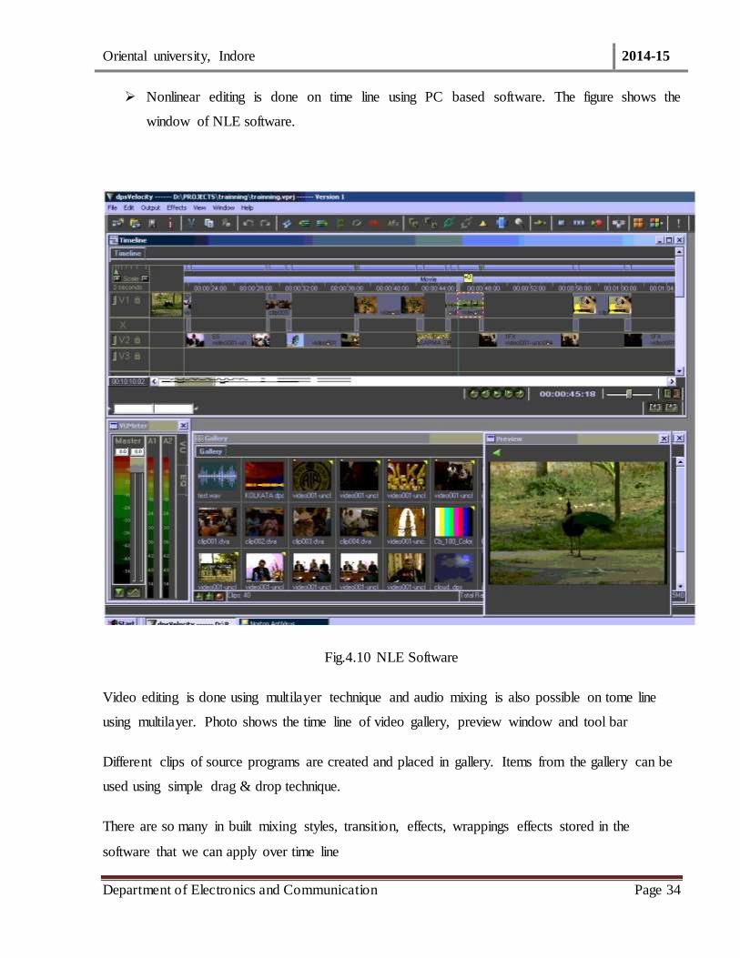
Nonlinear editing is done on time line using PC based software. The figure shows the
window of NLE software.
Fig.4.10 NLE Software
Video editing is done using multilayer technique and audio mixing is also possible on tome line
using multilayer. Photo shows the time line of video gallery, preview window and tool bar
Different clips of source programs are created and placed in gallery. Items from the gallery can be
used using simple drag & drop technique.
There are so many in built mixing styles, transition, effects, wrappings effects stored in the
software that we can apply over time line
Oriental university, Indore 2014-15
Department of Electronics and Communication Page 35
4.11 TRANSMITTER ANTENNA SYSTEM
TV Antenna system is that part of the Broadcast the Network which accepts RF energy from
transmitter and launches electromagnetic wave in space. The polarization of the radiation as
adopted by Doordashan is linear horizontal. The system is installed on a supporting tower and
consists of antenna panels, power dividers, blunts branch feeder cable lunation boxes and main
feeder cables. Dipole antenna elements in one of the other form are common at VHF frequencies
whereas slat antennae are mostly used at UHF frequency directional radiation pattern is obtain by
arranging the dipoles in the form of turnstile and exciting the same in quadrature phase . Desired
gain is obtained by stacking the dipoles in vertical plane. As a result of stacking most of the RF
energy is directed in the horizontal plane. Radiation in the vertical plane is minimized. The
installed antenna system should fulfill the following requirements:
It should have required gain and provide desired field strength at the point of reception.
It should have desired horizontal radiation pattern and direction for saving the planned area
of interest. The radiation pattern should be one direction if the location of the transmitting
station is at the service area direction one, if the location is otherwise.
It should offer proper impendence top the main feeder cable and thereby to the transmitter
so that optimum RF energy is transferred into space. Impedance mismatch results into
reflection of power and formation of standing waves. The standard RRF impedance at
VHF/UHF is 50 ohms.
Radiation Pattern and Gain
The horizontal and vertical radiation patterns are in the figures .The total gain depend upon
the type of the antenna panel and no. of stacks as in table -1.
Fig. 4.11 Doordarshan Logo

Oriental university, Indore 2014-15
Department of Electronics and Communication Page 36
4.12 DIGITAL SIDE BAND TRANSMISSION
Another feature of present day TV transmitter is vestigial side band transmission. If normal
amplitude modulation technique is used for picture transmission, the minimum transmission
channel bandwidth should be around 11 MHz taking into account the space for sound carrier
and a small guard band around of 0.25 MHz. Using such large transmission BW will limit the no.
of channels in the spectrum allotted for TV transmission. To accommodate large number of
channel in the allotted spectrum, reduction in transmission BW was considered necessary. The BW
could be reduced to around 5.75 MHz by using single side band (SSB) AM in technique because in
principle one side of the double side band (DBB) AM could be suppressed, since the two side band
have the same signal content.
It was not considered feasible to suppress one complete side band in the case of TV signals
most of the energy obtained in lower frequency and these frequency unless obtained important
information of the picture. If these frequencies are removed ,it causes objectionable phase
distortional these frequencies which will affect picture quality .Thus as a compromise only part of
lower side band is suppress while taking full advantage of the fact that ;
Visual disturbance due to phase energy and unacceptable where large picture are
concerned ( i.e., at LF ) but
Phase errors becomes for see on small details ( i.e. in HF region) in thee picture . Thus
low modulating frequencies must minimize phase distortion where as high frequencies
are tolerant of phase distortions as they are very difficult to see.
The radiated signal thus contains full upper side band together with carrier and vestige (remaining
part) of the partially suppressed LSB . The lower side band contains frequencies up to 0.75 MHz
with a supper of 0.5 MHz so that the final cut off 1.25 MHz
Standards The characteristics of the TV signal are sections 1 and 2 refer to CCCIR B/W standard.
Various other standards are given in table 4.12

Oriental university, Indore 2014-15
Department of Electronics and Communication Page 37
(SPECIFFICATION OF DOORDARSHAN)
TABLE-4.12
Frequency Range Vision /sound carrier spacing channel width
Vision sound carrier spacing 5.5 MHz
Channel width 7MHz (B) in VHF OR 8MHz (G) in UHF
Sound Modulation FM
FM deviation (maximum) ± 50 kHz
4.13 EARTH STATION
Earth station is the unit from where program signal is sent to the geo stationary satellite (Uplink)
Program signal transmitted by the satellite is received at the earth station (downlink).
For a given channel an earth station is provided a fixed uplink frequency, and a different but fixed
downlink frequency.
An earth station is comprises of following:
Digital Transmitter.
Parabolic Antenna.
Power supply unit.
The following figure depicts the basic block diagram of digital earth station.

Oriental university, Indore 2014-15
Department of Electronics and Communication Page 38

Oriental university, Indore 2014-15
Department of Electronics and Communication Page 39
Fig.4.13 block diagram of Earth Station DDK, Indore
Fig.4.14 Block diagram of Earth Station DDK ,Indore

Oriental university, Indore 2014-15
Department of Electronics and Communication Page 40
4.14 ANTENNA ARRAYS
Waves undergo a phenomenon called interference.
Not noticeable for different signals.
But for same signals (with perhaps different relative phase, amplitude)
patterns can be formed.
Used in many fields.
Radio, cell tower(dipole antennas).
Helical antennas.
High gain too: phased arrays.
Expensive, thermal management issues.
Satellites: many beams from one aperture.
Terminals: Rapid beam steering.
Fig. 4.14 Diagram of Parabolic Dish Antenna

Oriental university, Indore 2014-15
Department of Electronics and Communication Page 41
Conclusion
Now I have studied a lot about the television broadcast system. One must have never thought that
so many things are required for watching a television. The camera, the studio, the transmitter, the
PDA, the setup box (installed in houses) everything is connected to each other. Here man and
electronics work as if they are a family. So many process and lots of hard work, sincerity is
required to just have a show or say a movie on air i.e. to be broadcasted. So many people are
involved in it. I really enjoyed of being part of it. The saying is really true that…
“Tell me, I may forget
Teach me, I may remember
But involve me, and I have learnt it”

Oriental university, Indore 2014-15
Department of Electronics and Communication Page 42
REFERENCES
http://www.doordarshan.com
http://www.googleimage.com
Text material from DDK Indore