DOI: 10.1177/0021955X14546015 improve the modulus …velankar/www/papers/JCellPlastLobos2015.pdfJuan...
32
XML Template (2014) [25.8.2014–5:35pm] [1–32] //blrnas3/cenpro/ApplicationFiles/Journals/SAGE/3B2/CELJ/Vol00000/140041/APPFile/SG-CELJ140041.3d(CEL)[- PREPRINTER stage] Review Article How much do nanoparticle fillers improve the modulus and strength of polymer foams? Juan Lobos and Sachin Velankar Abstract Nanofiller reinforcing agents can significantly improve the strength and modulus of polymer foams. But these improvements are often accompanied by changes in foam density (or equivalently the expansion ratio or void volume). The efficacy of nanofillers as reinforcing agents can only be judged once the density differences are accounted for. We review the literature and show that representing the data on Ashby charts of modulus against foam density is an effective way of evaluating whether nanofillers have a significant reinforcing effect or not. The literature suggests that strength and improvements due to nanofiller – after accounting for foam density changes – are typically modest for thermoplastic foams. However, major improvements are possible for reactively generated foams, especially flexible polyurethane foams. Keywords Foam, filler, thermoplastic, porous, polyurethane Introduction Nanofillers such as carbon nanofibers (CNFs) or nanotubes, silica, or organoclays are often added to foamed polymers for a variety of reasons including increasing nucleation, reducing cell size, or improving barrier properties. In many such cases, the addition of nanofillers is also intended to improve the mechanical properties of the foams. Figure 1 illustrates an example of an especially dramatic improvement in the strength of polyurethane (PU) foams with addition of montmorillonite Department of Chemical Engineering, University of Pittsburgh, Pittsburgh, USA Corresponding author: Sachin Velankar, University of Pittsburgh, 1249 Benedum Hall, 3700 Ohara Street, Pittsburgh, PA 15261, USA. Email: [email protected] Journal of Cellular Plastics 2014, Vol. 0(0) 1–32 ß The Author(s) 2014 Reprints and permissions: sagepub.co.uk/journalsPermissions.nav DOI: 10.1177/0021955X14546015 cel.sagepub.com
Transcript of DOI: 10.1177/0021955X14546015 improve the modulus …velankar/www/papers/JCellPlastLobos2015.pdfJuan...

XML Template (2014) [25.8.2014–5:35pm] [1–32]//blrnas3/cenpro/ApplicationFiles/Journals/SAGE/3B2/CELJ/Vol00000/140041/APPFile/SG-CELJ140041.3d(CEL)[-PREPRINTER stage]
Review Article
How much donanoparticle fillersimprove the modulusand strength ofpolymer foams?
Juan Lobos and Sachin Velankar
Abstract
Nanofiller reinforcing agents can significantly improve the strength and modulus of
polymer foams. But these improvements are often accompanied by changes in foam
density (or equivalently the expansion ratio or void volume). The efficacy of nanofillers
as reinforcing agents can only be judged once the density differences are accounted for.
We review the literature and show that representing the data on Ashby charts of
modulus against foam density is an effective way of evaluating whether nanofillers
have a significant reinforcing effect or not. The literature suggests that strength and
improvements due to nanofiller – after accounting for foam density changes – are
typically modest for thermoplastic foams. However, major improvements are possible
for reactively generated foams, especially flexible polyurethane foams.
Keywords
Foam, filler, thermoplastic, porous, polyurethane
Introduction
Nanofillers such as carbon nanofibers (CNFs) or nanotubes, silica, or organoclaysare often added to foamed polymers for a variety of reasons including increasingnucleation, reducing cell size, or improving barrier properties. In many such cases,the addition of nanofillers is also intended to improve the mechanical properties ofthe foams. Figure 1 illustrates an example of an especially dramatic improvementin the strength of polyurethane (PU) foams with addition of montmorillonite
Department of Chemical Engineering, University of Pittsburgh, Pittsburgh, USA
Corresponding author:
Sachin Velankar, University of Pittsburgh, 1249 Benedum Hall, 3700 Ohara Street, Pittsburgh, PA 15261, USA.
Email: [email protected]
Journal of Cellular Plastics
2014, Vol. 0(0) 1–32
� The Author(s) 2014
Reprints and permissions:
sagepub.co.uk/journalsPermissions.nav
DOI: 10.1177/0021955X14546015
cel.sagepub.com

XML Template (2014) [25.8.2014–5:35pm] [1–32]//blrnas3/cenpro/ApplicationFiles/Journals/SAGE/3B2/CELJ/Vol00000/140041/APPFile/SG-CELJ140041.3d(CEL)[-PREPRINTER stage]
(MMT) clay: the addition of only a few weight percent clay improves the tensilestrength and the compressive strength by 110% and 152%, respectively.1 Manysuch examples of nanofiller-induced improvements in modulus or strength are citedin the literature2–6 and the supplementary information has compiled data fromnumerous articles showing similar results. A recent review article also commentedon the efficacy of nanofillers at improving foam properties.7 In the light of theseresults, the question ‘‘Do nanofillers improve modulus and strength of foams?’’seems to be answered with an unequivocal ‘‘Yes’’ in many cases. However, thisconclusion cannot be sustained solely based on data such as Figure 1 because thenanofiller may simultaneously change the foam density which itself affects mechan-ical properties. For instance, if the filler increases the density of the foam, onewould see an increase in strength for that reason alone – regardless of the reinfor-cing effect of the filler. Thus, for any practical application, the foam strength maybe improved by simply reducing the expansion (i.e., foaming to a higher density)rather than by adding a nanofiller. Depending on the costs of the nanofiller, thepolymer and the processing operation, increasing the density of the filler-free foammay be more economical than adding the filler to achieve the same final foamproperties. Clearly then, addressing the question posed in the title of this paperrequires accounting for changes in foam density with particle addition. The goal ofthis article is to examine – after accounting for the changes in foam density – theextent to which nanofillers affect foam mechanical properties.
Remarkably, a large number of articles on polymer foams, including Xu et al.1
(Figure 1), do not quote the density of the foams at all. Thus, a quantitative‘‘normalization’’ for the effect of foam density, or even a qualitative judgment ofwhether density changes may have affected the mechanical properties, is not
Figure 1. Compressive and tensile strength of PU foam/organoclay nanocomposites.1
2 Journal of Cellular Plastics 0(0)

XML Template (2014) [25.8.2014–5:35pm] [1–32]//blrnas3/cenpro/ApplicationFiles/Journals/SAGE/3B2/CELJ/Vol00000/140041/APPFile/SG-CELJ140041.3d(CEL)[-PREPRINTER stage]
possible from the data. There are also numerous articles,2,8–11 especially in themicrocellular foams literature, in which the foam density is not given explicitlybut the mean cell size and the cell number density, Nf, are both quoted. At firstglance, a combination of the two should give the foam density since
void volume fractionð Þ ¼ hVcellNfi ¼� 16�D3
cell
�Nf ¼ 1�
�foam�solid
� �ð1Þ
where Dcell and Vcell are the cell diameter and cell volume, respectively, and theangular brackets denote an average. However, there are potential problems withthis approach. Often the cell number density is calculated from electron microscopeimages of cross-sections of the foams using the equation2,12–14
Nf ¼n
A
� �32
ð2Þ
where n is the number of cells in an scanning electron microscope (SEM) cross-sectional image of area A. Equation (2) makes several assumptions including thatthe cells are isotropic, that the foam density is low, and that the cell size distribu-tion is not too polydisperse. If these assumptions are not met, equation (1) maygive wrong results. To further complicate matters, numerous articles do not specifyclearly how the average cell size has been calculated. Equation (1) requires that thecell size be the volume-weighted average hD3
celli1=3, whereas if the size-weighted
average, hDcelli, has been quoted, it would not be appropriate to use equation(1). Moreover, if the cells are anisotropic, each cell size is itself an average of itsdimensions along two orthogonal directions. In that case, calculating the averagecell volume from this average size would give incorrect results even if the cell sizepolydispersity was low. Finally, to further complicate matters, some articles15–18
report the cell density, N0, calculated as
N0 ¼n
A
� �32�solid�foam
ð3Þ
This N0 is the number of cells per unit volume of the unfoamed polymer whichcannot be used in equation (1). For all these reasons, applying equation (1) toestimate foam density may cause large errors. For instance, using equation (1)can sometimes19–23 yield an unphysical result that the �foam 5 0. This must notbe regarded an error in the values of cell density or of cell size quoted in the originalarticles since those values were not intended for back-calculating foam density.However, it does mean that data from those articles cannot be ‘‘normalized’’ toaccount for foam density variations.
Accordingly, this review is chiefly focused on articles in which the followingthree criteria were met (1) nanofiller-containing foams were compared against cor-responding nanofiller-free foams, (2) mechanical properties were measured, and (3)
Lobos and Velankar 3

XML Template (2014) [25.8.2014–5:35pm] [1–32]//blrnas3/cenpro/ApplicationFiles/Journals/SAGE/3B2/CELJ/Vol00000/140041/APPFile/SG-CELJ140041.3d(CEL)[-PREPRINTER stage]
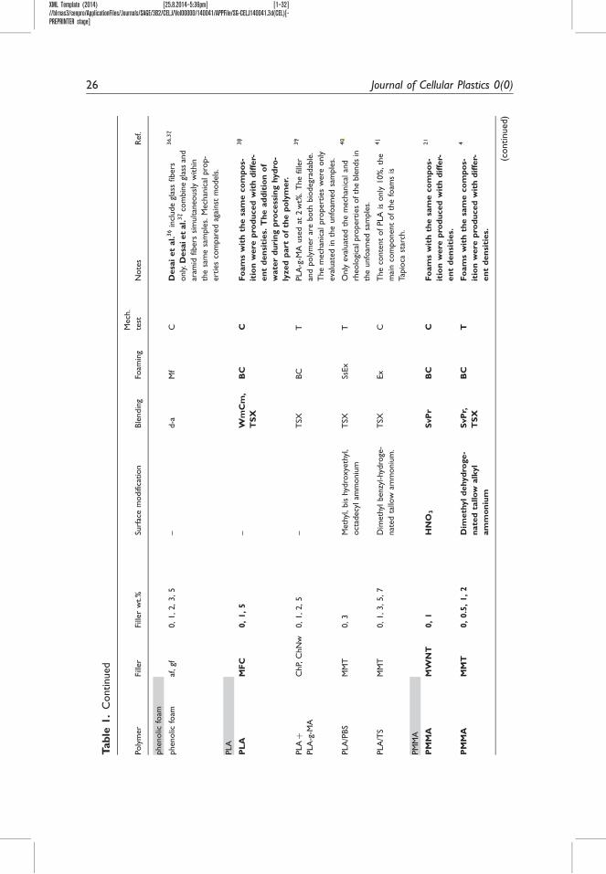
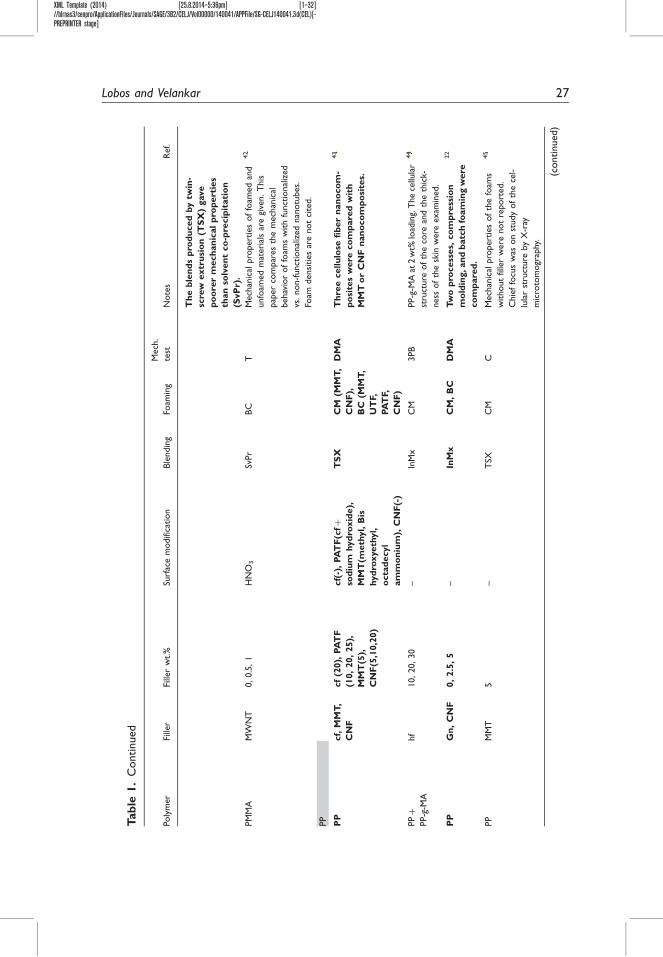
foam density was cited explicitly in the paper. Approximately 30 articles werefound to satisfy all the three criteria. The bold texted rows in Table 1 summarizesome of the key information in these papers: the polymer, the type and amount offiller, the foaming method, and which mechanical properties were measured. TheOnline Supplementary Information summarizes the mechanical property data ineach paper. Based on all of these articles, we conclude that (1) the improvement inmechanical properties due to nanofiller addition is typically modest for thermo-plastics, although occasional cases of much larger improvements have been docu-mented,8,21,24 (2) dramatic improvements are possible when the matrix isrubbery,3,6,25 (3) filler surface modification and the foaming operation can havea significant effect on the efficacy of reinforcement.2,11,26
In addition, there are numerous articles where the addition of nanofiller wasshown to affect mechanical properties, but foam density was not stated. Thesearticles are also included in Table 1, but datasheets for those papers are not pre-sented in the Online Supplementary Information.
The outline of this article is as follows. The next section discusses, with oneillustrative example, how differences in foam density may be accounted for whenjudging the reinforcement efficacy of nanofiller. Next, we will cite exemplary datasupporting the conclusions listed in the previous paragraphs. Finally, we will dis-cuss some potential mechanisms whereby the fillers can affect the mechanical prop-erties of foams.
Accounting for differences in foam density
Figure 2 illustrates an example of the Young’s modulus of foams reinforced byCNFs.8 Figure 2(a) compares the modulus of the foams obtained at two differentnanofiber loadings against the modulus of the filler-free foams. Foams of variousdensities, which have been tagged in Figure 2 as ‘‘low,’’ ‘‘medium,’’ and ‘‘high’’density, were obtained by varying the processing conditions. Three commentsmay be made (1) the modulus of the unfilled foam increases significantly withdensity which is well recognized in the foam literature,27 (2) under a given set ofprocessing conditions, the modulus increases with nanofiber addition analogousto Figure 1, and (3) the foam density also increases with nanofiber addition. Asmentioned in the Introduction section, it is the last effect that must be ‘‘sub-tracted out’’ when judging the efficacy of the nanofiller in improving mechanicalproperties.
One immediate solution may be to normalize the mechanical property ofeach foam by the foam density, e.g., by comparing specific strength or specificmodulus.3,6,11,28 This comparison is shown in Figure 2(b), and while the dif-ference between samples appears somewhat smaller, nanofiber addition stillappears to have a beneficial effect, i.e., it improves the specific modulus
Efoam
�foam.
Nevertheless, simple normalization by the density may not entirely account forfoam density variations because the mechanical properties of foams often varynon-linearly with density.27 For instance, in the limit of low densities, a wide
4 Journal of Cellular Plastics 0(0)
XML Template (2014) [25.8.2014–5:35pm] [1–32]//blrnas3/cenpro/ApplicationFiles/Journals/SAGE/3B2/CELJ/Vol00000/140041/APPFile/SG-CELJ140041.3d(CEL)[-PREPRINTER stage]
variety of foams have been shown to approximately follow a quadraticrelationship27
Efoam
Esolid¼ K
�foam�solid
� �2
ð4Þ
where K is nearly 1.27 Such a relationship suggests that the specific modulusEfoam
�foamis
not independent of the foam density: if a nanofiller doubles the foam density, thespecific modulus doubles even if the filler has no reinforcing effect at all. In such asituation, one may erroneously conclude that the nanofiller improves the mechan-ical properties, when in fact the nanofiller merely reduces foam expansion. Asmentioned in the Introduction, in such a case, the same improvement in moduluscould have been realized without nanofiller, simply by reducing the foam expan-sion. This same issue remains even if equation (4) is not exactly correct, or ifproperties other than modulus are under consideration: simply normalizing a prop-erty by density is justifiable only if that property is inherently proportional todensity.
The best solution then is to compare samples with and without nanofillers at aconstant foam density. This, however, is difficult since most foaming operationscannot control foam density accurately. More precisely, if the neat polymer and thefilled polymer are foamed under identical conditions, they will typically not havethe same density. In some cases, the changes in foam density due to nanofillerhappen to be quite small,26,29 and later in this article, one such case will be dis-cussed in greater detail. It is also possible to guarantee samples of exactly the samedensity by foaming in a closed mold, thus limiting the expansion to a pre-specifiedvalue.29–31 Even in such cases, however, a density gradient between the core and thewalls32–36 may provide misleading results. In extreme cases, the formation of a skinat the surface may significantly affect mechanical measurements, especially if thefoam density is very low. In summary, although foam properties ought to becompared at fixed foam density, such comparisons are often not possible.
The next best approach is to obtain the mechanical properties across a widerange of densities, e.g., finding the entire Efoam vs. �foam curve, often known asan Ashby chart,37,38 and then finding how this curve is affected by the additionof nanofillers. Indeed, the article of Shen et al.8 (Figure 2) provides threedensities at each nanofiber loading, allowing a rough modulus–density graphto be plotted (Figure 2(c)). The solid line corresponds to the quadratic depend-ence of equation (4) (with K ¼ 1), which seems to capture the modulus–densityrelationship for the filler-free foams at least approximately. At the lowestdensities, the nanofiller-containing foams appear to follow this same relation-ship almost quantitatively, suggesting that a comparable modulus improvementmight have been obtained by reducing foam expansion rather than by addingnanofiller. At higher density, however, the modulus appears to increase moresharply than the solid line suggesting that nanofiller addition may have areinforcing effect.
Lobos and Velankar 5

XML Template (2014) [25.8.2014–5:35pm] [1–32]//blrnas3/cenpro/ApplicationFiles/Journals/SAGE/3B2/CELJ/Vol00000/140041/APPFile/SG-CELJ140041.3d(CEL)[-PREPRINTER stage]
Figure 2. (a) Young’s modulus of the PS-CNF foams.8 (b) Specific modulus of the PS-CNF
foams (ratio of modulus to density). (c) Ashby chart of modulus vs. density. Note that the
moduli of the low- and medium-density foams were measured in compression while the
moduli of the high-density samples were measured in tension.
6 Journal of Cellular Plastics 0(0)

XML Template (2014) [25.8.2014–5:35pm] [1–32]//blrnas3/cenpro/ApplicationFiles/Journals/SAGE/3B2/CELJ/Vol00000/140041/APPFile/SG-CELJ140041.3d(CEL)[-PREPRINTER stage]
Admittedly, Figure 2 shows only three points on the modulus–density curve;moreover, the moduli of different samples were measured differently (in tension forthe high-density foam and in compression for the medium- and low-density foams).Therefore, the conclusion of the previous paragraph is only tentative. Nevertheless,if more data were collected, this approach offers the potential for drawing unam-biguous conclusions about whether the nanofiller truly has a reinforcing effect. Theadvantage of this approach is that it is purely experimental and does not depend onspecific models of foam mechanics: the sole criterion is whether the properties offoams with nanofiller systematically lie above or below the curve for foams withoutfiller. For instance, Figure 7 illustrates such an example where the modulus–densitycurve for filled foams is consistently above that of the unfilled foams indicating atrue reinforcing effect.21 In contrast, Zhang et al.39 (see corresponding graph in theSupplementary Information) show an excellent example where nanofiller induceslarge change in the modulus, strength, and density, yet, foams with and withoutnanofiller fall on exactly the same curve. These results39 suggest that the dominantrole of the nanofiller in Zhang et al. is simply reducing foam expansion with little orno reinforcing effect.
The disadvantage of this approach is that it is experimentally tedious: it requiressufficient number of samples that a continuous curve of Efoam vs. �foam can bedrawn with confidence. In fact only a few articles4,8,21,40 have reported samplesat sufficient number of densities that such a curve can be drawn at all. Nevertheless,this idea of comparing foams on an Ashby chart where a particular property isplotted against density is very useful: it can not only judge whether nanofilleraddition has a beneficial effect but also identify which particle loadings, particletypes, or foaming conditions offer the greatest improvements. Accordingly, all thedata in this paper and in the Online Supplementary information are compiled inthis form of Ashby charts. In the following section, we will present data fromspecific articles that have been selected to illustrate the key effects of nanofilleron foam mechanics.
Nanofiller effects in polymer foams
Figure 3 compares the Young’s modulus data for a single material, polystyrene(PS), from four different papers,2,8,24,41 including the article of Figure 2. To ourknowledge, these four are the only papers on PS foams which satisfy the threecriteria listed at the end of the Introduction section, viz. using nanofillers, citingfoam density, and measuring mechanical properties. The lines with slope 2 corres-pond to equation (4), where Esolid was assigned the modulus of the unfoamed filler-free PS quoted in each paper. In each case, the unfilled points correspond to thefoams without filler, and in each, equation (4) is found to be in qualitative agree-ment with the results although deviations of as much as 1.5� (in either direction)are sometimes evident. Various nanofiller types, and at various filler loadings areincluded in Figure 3. The advantage of representing the data in this form is espe-cially evident for the data of Han et al.2 shown as purple diamonds; here the fillers
Lobos and Velankar 7

XML Template (2014) [25.8.2014–5:35pm] [1–32]//blrnas3/cenpro/ApplicationFiles/Journals/SAGE/3B2/CELJ/Vol00000/140041/APPFile/SG-CELJ140041.3d(CEL)[-PREPRINTER stage]
increase both the foam density and modulus significantly, but these filler-containingfoams do not deviate much from the quadratic line. This behavior is similar to that ofZhang et al.39 mentioned above. Thus, if equation (4) is valid for these foams, thenwe would conclude that the improvements in foam properties are entirely attribut-able to nanofiller-induced changes in foam density rather than nanofiller-inducedreinforcement. Examining Figure 3, the filler effects appear modest for most sam-ples. In fact, the data on all the papers in the Online Supplementary Informationsuggest that this is true for a majority of thermoplastic foams: the improvements inmodulus or strength are typically below 20%. Nevertheless, it must be emphasizedthat the y-axis in Figure 3 is a logarithmic scale spanning over three orders of mag-nitude; such a large-scale magnitude can mask some significant improvements. Moststrikingly, in the case of the MMT-reinforced foams from Ogunsona et al.24 (greentriangles in Figure 3, which correspond to different MMT loadings), the filler sim-ultaneously induces an almost two-fold decrease in foam density and a two-foldincrease in modulus. There are a few other examples in the literature where similarlarge improvements of strength or modulus were realized.8,21,42 In summary, Figure3 illustrates the value of uniting different data for a single thermoplastic onto a singlegraph: it has the potential to identify filler types or filler loadings that can give thegreatest improvement in properties.
Not only the nature of the solid filler used but the processing conditions mayalso affect the improvement in mechanical properties. Figure 4 illustrates an exam-ple of LDPE foams prepared by two different methods:11,30 batch foaming (BF)
Figure 3. Modulus of the PS foams vs. density.2,8,24,48 The lines correspond to equation (4).
The elliptical boundaries correspond to the envelope of properties expected from closed- and
open-celled polymeric foams.72,73 See Table 1 for abbreviations.
8 Journal of Cellular Plastics 0(0)

XML Template (2014) [25.8.2014–5:35pm] [1–32]//blrnas3/cenpro/ApplicationFiles/Journals/SAGE/3B2/CELJ/Vol00000/140041/APPFile/SG-CELJ140041.3d(CEL)[-PREPRINTER stage]
using carbon dioxide and improved compression molding (ICM) using a chemicalblowing agent. In the BF method, samples were saturated with CO2 at high pres-sure and temperature, and then the pressure was decreased rapidly with simultan-eous cooling. In this case, the addition of nanosilica was seen to reduce the densitywith a slight improvement in modulus and collapse stress, at least at the 3% and6% silica loading. In the ICM method, the polymers, blended with 5% of azodi-carbonamide as a blowing agent, were introduced into a cylindrical mold in a hotplate press. The blowing agent was allowed to decompose by heating without
Figure 4. Effect of processing conditions on the mechanical properties of LDPE foams with
nanosilica (nS).11,29 The quadratic lines correspond to equation (4) in the text and 5.18 b in
Gibson and Ashby.65
Lobos and Velankar 9

XML Template (2014) [25.8.2014–5:35pm] [1–32]//blrnas3/cenpro/ApplicationFiles/Journals/SAGE/3B2/CELJ/Vol00000/140041/APPFile/SG-CELJ140041.3d(CEL)[-PREPRINTER stage]
permitting foam expansion, followed by rapid foam expansion and simultaneouscooling. In this case, the filler was seen to increase the modulus significantly, atleast up to 6% silica, along with a modest increase in foam density. Thus, the effectof filler loading is qualitatively consistent in the two experiments (best improve-ment appears at 3–6% loading in both cases), although the actual density valuesrealized are somewhat different. It is noteworthy that regardless of foaming tech-nique, the method used for dispersion of the nanofiller into the thermoplastic wasidentical; thus, the difference in foam properties is not likely due to the state ofdispersion of the nanosilica, but instead due to differences in the foam structure(in particular, the open cell content) obtained from the two different processes.11
Incidentally, in the case of BF, the modulus increased while density reduced – acombination that strongly suggests that the nanofiller does have a reinforcingeffect. As with Ogunsona et al.24 discussed in the previous paragraph, in suchsituations the filler reinforcement effect is clearly evident even though samplesare not compared at fixed foam density.
The surface chemistry of the filler can also affect the foam properties. First, favor-able interactions between the polymer and the filler can improve the dispersion of thefiller. Second, the adhesion between the filler and the polymer, which is critical forstress transfer from the polymer to the filler, may also be improved with appropriatesurface chemistry. Such chemical interactions can be improved by including func-tional groups into the polymer to act as compatibilizing agents. Indeed, Table 1shows numerous cases in which maleated polymers are added as compatibilizers.It is also common in the nanoclay composite literature to use organic modification ofthe clay to improve compatibility with the polymer.43–46 Such compatibilization canhave a significant effect on mechanical properties as exemplified in Figure 5. Thisfigure shows the tensile strength and ultimate elongation of ethyl vinyl acetate foamswith MMT clay nanofiller26 at a single filler loading of 3wt%. In addition to thenative unmodified MMT clay, three organoclays were used. As clear from Figure 5,
Figure 5. Effect of different clay types (all at 3 wt% loading) on the mechanical properties of
ethyl vinyl acetate foams.26
10 Journal of Cellular Plastics 0(0)

XML Template (2014) [25.8.2014–5:36pm] [1–32]//blrnas3/cenpro/ApplicationFiles/Journals/SAGE/3B2/CELJ/Vol00000/140041/APPFile/SG-CELJ140041.3d(CEL)[-PREPRINTER stage]
although clays improved the strength and ultimate elongation in all cases, there wasa significant effect of the type of clay used, with the best improvement coming from aclay dubbed D1821-MMT which was MMT modified with a surfactant havinghighly hydrophobic tail. These differences in mechanical properties with clay func-tionalization were shown to be directly related to the quality of dispersion of clay asjudged by SAXS: the nativeNa-functionalMMTand the hydroxyl-functionalMMThad the worst dispersion and the least improvement in strength, whereas the orga-noclays D1821-MMT and 1831-MMThad the best dispersion and greatest improve-ment in strength.More details of the chemical nature of the organic modification areavailable in Table 1 and in the supplementary datasheet.
The data of this figure are unusual in that because the foaming was conducted bycompression molding in a closed mold, all the foams have nearly the same density.Thus, this is a rare example of where the reinforcing effect of nanofiller can be madequantitativewithout normalizing for foam density. Incidentally, it is noteworthy thatin organoclays, the organic surfactant comprises a significant fraction of the massand volume of the clay. Thus, even though all the foams contained 3% by weight ofthe organoclay, the fraction of the aluminosilicate platelets, which are the actualreinforcing agent, was not constant. In the case of Na-functional MMT, all of themass of the clay was capable of being a reinforcing agent, whereas in the otherextreme of D1821-MMT, only 65% of the clay mass could act as a reinforcingagent (the remaining 35% being surfactant). Thus, it is noteworthy that theD1821 clay increased the strength of the foams to a greater extent even though theloading of the actual reinforcing agent was lower. This testifies to importance of thebetter dispersion and adhesion realized due to the organic modifier.
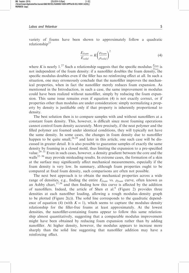
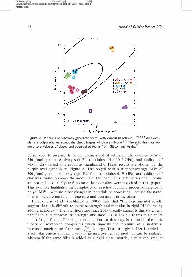
We now turn from thermoplastic foams to reactive foams in which a low-mole-cular weight fluid is converted, in a single step, into polymer foam. These aretypically PU foams made by reaction between polyol and isocyanate, with severalother ingredients included in the reacting mixture. The foam expansion occurseither due to the boiling of a physical blowing agent such as a fluorocarbonmixed into the reacting mixture, or due to the reaction of one component of thereacting mixture with water. In such systems, foaming, polymerization, and oftencrosslinking or vitrification of the polymer, all happen simultaneously. Even in theabsence of nanofiller, the situation is complicated because changes in foam densitymay go hand-in-hand with changes in the composition or glass transition tempera-ture or crosslink density of the solid phase. Moreover, properties of the unfoamedsolid phase, e.g., Esolid, are difficult to measure since it can be difficult to reproducethe exact same material in unfoamed form. Accordingly Figure 6, which summar-izes modulus of some reactive foams, does not show any data for the unfoamedpolymer. What is most noteworthy is that unlike thermoplastic foams, significantimprovements due to nanofiller addition – either a decrease in foam density with-out loss of modulus, or an increase in modulus at fixed density, or both – are seenin many cases. However, these improvements can depend severely on the materialsused. An excellent illustration of this is provided in Cao et al.3 where two PU foamswere examined, with the only difference being the molecular weight of the polyester
Lobos and Velankar 11
XML Template (2014) [25.8.2014–5:36pm] [1–32]//blrnas3/cenpro/ApplicationFiles/Journals/SAGE/3B2/CELJ/Vol00000/140041/APPFile/SG-CELJ140041.3d(CEL)[-PREPRINTER stage]
polyol used to prepare the foam. Using a polyol with a number-average MW of540 g/mol gave a relatively soft PU (modulus 1:4� 10�4 GPa), and addition ofMMT clay raised this modulus significantly. These results are shown by thepurple oval symbols in Figure 6. The polyol with a number-average MW of300 g/mol gave a relatively rigid PU foam (modulus 0:19 GPa) and addition ofclay was found to reduce the modulus of the foam. This latter series of PU foamsare not included in Figure 6 because their densities were not cited in that paper.3
This example highlights the complexity of reactive foams: a modest difference inpolyol MW – with no other changes in materials or processing – caused the nano-filler to increase modulus in one case and decrease it in the other.
Finally, Cao et al.3 (published in 2005) state that ‘‘the experimental resultssuggest that it is difficult to increase strength and modulus in rigid PU foams byadding nanoclay.’’ The later literature since 2005 broadly supports this statement:nanofillers can improve the strength and modulus of flexible foams much morethan of rigid foams. One simple explanation for this may be rooted in the basictheory of reinforced composites which suggests the modulus of a matrix isincreased much more if the ratio
Efiller
Ematrixis large. Thus, if a given filler is added to
a soft elastomeric matrix, a very large improvement in modulus can be realized,whereas if the same filler is added to a rigid glassy matrix, a relatively smaller
Figure 6. Modulus of reactively generated foams with various nanofillers.3,10,52–54 All exam-
ples are polyurethanes except the pink triangles which are silicone.6,25 The solid lines corres-
pond to envelopes of closed and open-celled foams from Gibson and Ashby.65
12 Journal of Cellular Plastics 0(0)

XML Template (2014) [25.8.2014–5:36pm] [1–32]//blrnas3/cenpro/ApplicationFiles/Journals/SAGE/3B2/CELJ/Vol00000/140041/APPFile/SG-CELJ140041.3d(CEL)[-PREPRINTER stage]
improvement can be realized. Since the material comprising the cell walls of thefoam is a nanofiller-reinforced composite, this suggests that nanofillers are likely tobe more effective at modifying the properties of foams made from low-moduluspolymers. Indeed, this is borne out by Figure 6: the greatest improvement in modu-lus appears for the flexible PU foam from Cao et al.3 and the silicone foams ofVerdejo et al.6,25 – materials in which the nanofiller is added to a soft polymer.
Finally, we turn to discussing the potential mechanisms whereby nanofillers mayimprove the mechanical properties. Perhaps the simplest is equation (4) which sug-gests that the modulus of a foam is proportional to the modulus of the solid com-ponent of the foam. Even if the dependence on foam density is different,21 fromwhatis predicted by equation (4), the basic idea is still valid: since nanofillers oftenimprove the modulus of unfoamed polymers, a proportionate improvement in thefoam modulus may be expected. Similar correlations have been developed for othermechanical properties,27 and in most cases, any given foam property is proportionalto the corresponding property of the solid material comprising the cell walls. Thus, itis of interest to compare the degree to which nanoparticles improve the mechanicalproperties of the foams versus those of the unfoamed polymer. Such comparisonscan be done only infrequently using the published literature since many articles donot document the effect of nanofiller on the unfoamed polymer. A nice examplewhich does provide data on both the foamed as well as unfoamed nanocompositesis Chen et al.21 The results from this paper are illustrated in Figure 7, which comparesthe modulus of foamed and unfoamed poly(methyl methacrylate) (PMMA) contain-ing two different CNFs.21 For the foams without added nanofibers, the dependenceon modulus on density does not follow equation (4); instead the modulus appears todecrease less sharply with density. Regardless, with the addition of F100 nanofibers,
Figure 7. Modulus of PMMA foams containing two different carbon nanofibers.21
Lobos and Velankar 13

XML Template (2014) [25.8.2014–5:36pm] [1–32]//blrnas3/cenpro/ApplicationFiles/Journals/SAGE/3B2/CELJ/Vol00000/140041/APPFile/SG-CELJ140041.3d(CEL)[-PREPRINTER stage]
the general shape of the modulus–density curve is seen to remain the same but thecurves move upwards by a factor that is roughly the same as themodulus increase forthe unfoamed polymer. These results argue in favor of a very simple picture that thenanofiller affects Efoam and Esolid in exactly the same way: the foam is stiffer simplybecause the F100 nanofibers make the material of the cell walls stiffer.
We speculate that Efoam / Esolid is not necessarily true, and more complex behaviormay be possible. Indeed, for the sample containing F20 nanofibers in Figure 7, nano-fiber addition seems to increase Efoam more than Esolid. If the filler is highly anisotropic,one possible reason for thismay be filler orientation. The filler in the unfoamed polymeris typically unaligned, whereas upon foaming, the filler can orient parallel to the cellwalls.8,42,47 In reinforced composites, filler alignment generally improves the modulusand strength along the alignment direction. Thus, high-aspect ratio nanoparticlesmightimprove the modulus to a greater extent in a foam (due to well-oriented filler in the cellwalls) than in the unfoamed polymer (in which the filler is isotropically oriented).
On the other hand, it is also possible for the filler particles to serve as cell-opening agents. While we have not found any example of this being true in thermo-plastic foams, this has been documented in PU foams,48,49 and indeed nanofillersmay be added to PU foams specifically for this purpose. Models of foam mechanicssuggest that decreasing the open cell content reduces the modulus27; thus, evenparticles that are good reinforcing agents in an unfoamed polymer may end upreducing the modulus once the polymer is foamed. In such cases, not just moduluschanges, but many other large changes in mechanical behavior may be expected.
Cell size may also play a role. Frequently, the addition of nanoparticles increasesthe nucleation50; thus, if samples are compared at the same foam density, a highernucleation density also implies a significantly smaller cell size. While the models ofGibson and Ashby27 predict that most mechanical properties are independent ofcell size, in reality, some cell size dependence may be present. The available data donot allow a definitive conclusion on whether nanofillers affect the mechanical prop-erties via their effect on the cell size.
Conclusion
In summary, the efficacy of nanofiller at improving the strength and modulus ofpolymer foams can only be judged after the effects of nanofiller on foam density arecontrolled for. However, preparing foams with and without filler at exactly the samedensity is difficult. We show that comparisons of filled and unfilled foams across arange of densities are a powerful method of judging whether nanofillers have reinfor-cing effects. The same comparisons can identify which nanofillers are most efficaciousand at what loadings. Furthermore, nanofiller can affect foam mechanical propertiesin many ways, e.g., mechanical reinforcement of the matrix, alignment of filler in thefoam walls, changes in the open cell content, etc. Identifying which of these mechan-isms is active becomes possible once the effects of foam density are accounted for.
The chief conclusions of this review are that improvements in modulus or strengthexceeding few 10% (holding foam density fixed) are uncommon for thermoplastic
14 Journal of Cellular Plastics 0(0)
XML Template (2014) [25.8.2014–5:36pm] [1–32]//blrnas3/cenpro/ApplicationFiles/Journals/SAGE/3B2/CELJ/Vol00000/140041/APPFile/SG-CELJ140041.3d(CEL)[-PREPRINTER stage]
foams, but more common for soft elastomeric foams often made by reactive foaming.Moreover, the efficacy of nanofillers depends on processing conditions and on thesurface chemistry of filler. Finally, we note that several articles1,20,23,31,51 on the mech-anical properties of nanofiller-containing foams were excluded from this reviewbecause density was not cited explicitly. However, density is perhaps the most import-ant attribute of foams and ought to be quoted in most research on foamed plastics.
This review focuses only on the narrow issue of how nanofiller affects mechanicalproperties. Nanofiller can have numerous other beneficial effects: nucleating foambubbles,47,51,52 decreasing the cell size,53–55 acting as diffusion barriers,56–58 increasingelectrical conductivity,59,60 stabilizing the foams through interfacial adsorption,61 sta-bilizing foam through reduced crystallinity,62,63 improving fire retartance,64 reducingthermal conductivity,65,66 and increasing open cell content.48 For some of these prop-erties, the questions central to this review may be posed, e.g., how much does thermalconductivity reduce once samples are compared at the same foam density? Whichnanofillers reduce thermal conductivity to the greatest extent once foam density vari-ations are accounted for? What nanofiller loadings are optimal? Addressing thesequestions will promote the optimal use of nanofillers in polymer foams.
Conflict of interest
None declared.
Funding
This research was supported by NSF-CMMI grant #1252850.
References
1. Xu Z, Tang X, Gu A, et al. Novel preparation and mechanical properties ofrigid polyurethane foam/organoclay nanocomposites. J Appl Polym Sci 2007; 106:439–447.
2. Han X, Zeng C, Lee LJ, et al. Extrusion of polystyrene nanocomposite foams with
supercritical CO2. Polym Eng Sci 2003; 43: 1261–1275.3. Cao X, James Lee L, Widya T, et al. Polyurethane/clay nanocomposites foams: process-
ing, structure and properties. Polymer 2005; 46: 775–783.
4. Fu J and Naguib HE. Effect of nanoclay on the mechanical properties of PMMA/claynanocomposite foams. J Cell Plast 2006; 42: 325–342.
5. Saha MC, Kabir ME and Jeelani S. Enhancement in thermal and mechanical
properties of polyurethane foam infused with nanoparticles. Mater Sci Eng: A 2008;479: 213–222.
6. Verdejo R, Saiz-Arroyo C, Carretero-Gonzalez J, et al. Physical properties of silicone foams
filled with carbon nanotubes and functionalized graphene sheets. Eur Polym J 2008; 44:2790–2797.
7. Chen L, Rende D, Schadler LS, et al. Polymer nanocomposite foams. J Mater Chem A2013; 1: 3837–3850.
8. Shen J, Han X and Lee LJ. Nanoscaled reinforcement of polystyrene foams using carbonnanofibers. J Cell Plast 2006; 42: 105–126.
Lobos and Velankar 15

XML Template (2014) [25.8.2014–5:36pm] [1–32]//blrnas3/cenpro/ApplicationFiles/Journals/SAGE/3B2/CELJ/Vol00000/140041/APPFile/SG-CELJ140041.3d(CEL)[-PREPRINTER stage]
9. Antunes M, Maspoch ML and Velasco JI (eds.) The multi-scalar effect of incorporating
nanofillers and cellulosic-based reinforcements into polyurethane foams: towards thedevelopment of low cost structural lightweight materials. International Conference onFoam Materials & Technology FOAMS 2012; Barcelona.
10. Madaleno L, Pyrz R, Crosky A, et al. Processing and characterization of polyurethanenanocomposite foam reinforced with montmorillonite–carbon nanotube hybrids.Compos Part A: Appl Sci Manuf 2013; 44: 1–7.
11. Saiz-Arroyo C, Rodrıguez-Perez MA, Velasco JI, et al. Influence of foaming process on
the structure–properties relationship of foamed LDPE/silica nanocomposites. ComposPart B: Eng 2013; 48: 40–50.
12. Kumar V and Suh NP. A process for making microcellular thermoplastic parts. Polym
Eng Sci 1990; 30: 1323–1329.13. Kumar V and Weller J. Production of microcellular polycarbonate using carbon dioxide
for bubble nucleation. J Eng Ind 1994; 116: 413–420.
14. Wang C, Ying S and Xiao Z. Preparation of short carbon fiber/polypropylene fine-celled foams in supercritical CO2. J Cell Plast 2012; 49: 65–82.
15. Khorasani MM, Ghaffarian SR, Babaie A, et al. Foaming behavior and cellular struc-ture of microcellular HDPE nanocomposites prepared by a high temperature process.
J Cell Plast 2010; 46: 173–190.16. Jiang XL, Bao JB, Liu T, et al. Microcellular foaming of polypropylene/clay nanocom-
posites with supercritical carbon dioxide. J Cell Plast 2009; 45: 515–538.
17. Lee JWS, Park CB and Kim SG. Reducing material costs with microcellular/fine-celledfoaming. J Cell Plast 2007; 43: 297–312.
18. Nofar M, Majithiya K, Kuboki T, et al. The foamability of low-melt-strength
linear polypropylene with nanoclay and coupling agent. J Cell Plast 2012; 48: 271–287.19. Hwang S-s, Hsu PP, Yeh J-m, et al. Effect of organoclay on the mechanical/thermal
properties of microcellular injection molded polystyrene–clay nanocomposites. Int
Commun Heat Mass Trans 2009; 36: 799–805.20. Hwang S-s, Liu S-p, Hsu PP, et al. Effect of organoclay on the mechanical/thermal
properties of microcellular injection molded PBT–clay nanocomposites. Int CommunHeat Mass Trans 2010; 37: 1036–1043.
21. Chen L, Schadler LS and Ozisik R. An experimental and theoretical investigation of thecompressive properties of multi-walled carbon nanotube/poly(methyl methacrylate)nanocomposite foams. Polymer 2011; 52: 2899–2909.
22. Antunes M, Gedler G and Velasco JI. Multifunctional nanocomposite foams based onpolypropylene with carbon nanofillers. J Cell Plast 2013; 49: 259–279.
23. Hwang S-s, Hsu PP, Yeh J-m, et al. Effect of clay and compatibilizer on the mechanical/
thermal properties of microcellular injection molded low density polyethylene nanocom-posites. Int Commun Heat Mass Trans 2009; 36: 471–479.
24. Ogunsona E, Ogbomo S, Nar M, et al. Thermal and mechanical effects in polystyrene-
montmorinonite nanocomposite foams. Cell Polym 2011; 30: 79–94.25. Verdejo R, Barroso-Bujans F, Rodriguez-Perez MA, et al. Functionalized graphene
sheet filled silicone foam nanocomposites. J Mater Chem 2008; 18: 2221–2226.
26. Ma J, Deng F, Xue C, et al. Effect of modification of montmorillonite on the cellularstructure and mechanical properties of ethylene vinyl acetate/clay nanocompositefoams. J Reinf Plast Compos 2012; 31: 1170–1179.
16 Journal of Cellular Plastics 0(0)

XML Template (2014) [25.8.2014–5:36pm] [1–32]//blrnas3/cenpro/ApplicationFiles/Journals/SAGE/3B2/CELJ/Vol00000/140041/APPFile/SG-CELJ140041.3d(CEL)[-PREPRINTER stage]
27. Gibson LJ and Ashby MF. Cellular solids: structure and properties. Cambridge, MA:
Cambridge University Press, 1999, p.532.28. Liao X, Nawaby AV and Naguib HE. Porous poly(lactic acid) and PLA-nanocomposite
structures. J Appl Polym Sci 2012; 124: 585–594.
29. Patro TU, Harikrishnan G, Misra A, et al. Formation and characterization of polyur-ethane-vermiculite clay nanocomposite foams. Polym Eng Sci 2008; 48: 1778–1784.
30. Saiz-Arroyo C, Escudero J, Rodriguez-Perez MA, et al. Improving the structure andphysical properties of LDPE foams using silica nanoparticles as an additive. Cell Polym
2011; 30: 63–78.31. Zeng C, Hossieny N, Zhang C, et al. Morphology and tensile properties of PMMA
carbon nanotubes nanocomposites and nanocomposites foams. Compos Sci Technol
2013; 82: 29–37.32. Rodriguez-Perez MA, Lobos J, Perez-Munoz CA, et al. Mechanical response of poly-
ethylene foams with high densities and cell sizes in the microcellular range. J Cell Plast
2009; 45: 389–403.33. Rodriguez-Perez MA, Lobos J, Perez-Munoz CA, et al. Mechanical Behaviour at low
strains of LDPE foams with cell sizes in the microcellular range: advantages of usingthese materials in structural elements. Cell Polym 2008; 27: 347–362.
34. Bledzki AK, Rohleder M, Kirschling H, et al. Correlation between morphology andnotched impact strength of microcellular foamed polycarbonate. J Cell Plast 2010; 46:415–440.
35. Reza Barzegari M and Rodrigue D. Tensile modulus prediction of structural foamsusing density profiles. Cell Polym 2008; 27: 285–301.
36. Rodrigue D. Using density profiles to predict the flexural modulus of structural polymer
foams. J Cell Plast 2008; 44: 381–389.37. Ashby MF and Johnson K. Materials and design: the art and science of material selection
in product design. UK: Butterworth-Heinemann, 2002.
38. Ashby MF. Materials selection in mechanical design, 3rd ed. UK: Butterworth-Heinemann, 2005.
39. Zhang L, Yilmaz ED, Schjødt-Thomsen J, et al. MWNT reinforced polyurethane foam:processing, characterization and modelling of mechanical properties. Compos Sci
Technol 2011; 71: 877–884.40. Jo C and Naguib HE. Effect of nanoclay and foaming conditions on the mechanical
properties of HDPE-clay nanocomposite foams. J Cell Plast 2007; 43: 111–121.
41. Guo Z, Yang J, Wingert MJ, et al. Comparison of carbon nanofibers and activatedcarbon on carbon dioxide foaming of polystyrene. J Cell Plast 2008; 44: 453–468.
42. Okamoto M, Nam PH, Maiti P, et al. Biaxial flow-induced alignment of silicate layers in
polypropylene/clay nanocomposite foam. Nano Lett 2001; 1: 503–505.43. Pegoretti A. Tensile mechanical response of polyethylene – clay nanocomposites.
eXPRESS Polym Lett 2007; 1: 123–131.
44. Sinha Ray S and Okamoto M. Polymer/layered silicate nanocomposites: a review frompreparation to processing. Prog Polym Sci 2003; 28: 1539–1641.
45. AlexandreM andDubois P. Polymer-layered silicate nanocomposites: preparation, prop-erties and uses of a new class of materials. Mater Sci Eng: R: Reports 2000; 28: 1–63.
46. Fornes TD, Hunter DL and Paul DR. Nylon-6 nanocomposites from alkylammonium-modified clay: the role of alkyl tails on exfoliation.Macromolecules 2004; 37: 1793–1798.
Lobos and Velankar 17

XML Template (2014) [25.8.2014–5:36pm] [1–32]//blrnas3/cenpro/ApplicationFiles/Journals/SAGE/3B2/CELJ/Vol00000/140041/APPFile/SG-CELJ140041.3d(CEL)[-PREPRINTER stage]
47. Nam PH, Maiti P, Okamoto M, et al. Foam processing and cellular structure of poly-
propylene/clay nanocomposites. Polym Eng Sci 2002; 42: 1907–1918.48. Harikrishnan G, Patro TU and Khakhar DV. Polyurethane foam-clay nanocomposites:
nanoclays as cell openers. Ind Eng Chem Res 2006; 45: 7126–7134.
49. Danowska M, Piszczyk L, Strankowski M, et al. Rigid polyurethane foams modifiedwith selected layered silicate nanofillers. J Appl Polym Sci 2013; 130: 2272–2281.
50. Eaves D and (ed.). Handbook of polymer foams. UK: Smithers Rapra Publishing, 2004.51. Ngo TTV, Duchet-Rumeau J, Whittaker AK, et al. Processing of nanocomposite foams in
supercritical carbon dioxide. Part I: effect of surfactant. Polymer 2010; 51: 3436–3444.52. Strauss W and D’Souza NA. Supercritical CO2 processed polystyrene nanocomposite
foams. J Cell Plast 2004; 40: 229–241.
53. Shen J, Zeng C and Lee LJ. Synthesis of polystyrene–carbon nanofibers nanocompositefoams. Polymer 2005; 46: 5218–5224.
54. Di Y, Iannace S, Maio ED, et al. Poly(lactic acid)/organoclay nanocomposites: thermal,
rheological properties and foam processing. J Polym Sci Part B: Polym Phys 2005; 43:689–698.
55. Mitsunaga M, Ito Y, Ray SS, et al. Intercalated polycarbonate/clay nanocomposites:nanostructure control and foam processing. Macromol Mater Eng 2003; 288: 543–548.
56. Widya T and Macosko C. Nanoclay modified rigid polyurethane foam. J Macromol SciPart B: Phys 2005; 44: 897–908.
57. Yuan H, Little JC, Marand E, et al. Using fugacity to predict volatile emissions from
layeredmaterialswith a clay/polymer diffusion barrier.AtmosEnviron 2007; 41: 9300–9308.58. Guo Z, Lee LJ and Tomasko DL. CO2 permeability of polystyrene nanocomposites and
nanocomposite foams. Ind Eng Chem Res 2008; 47: 9636–9643.
59. Thomassin J-M, Pagnoulle C, Bednarz L, et al. Foams of polycaprolactone/MWNTnanocomposites for efficient EMI reduction. J Mater Chem 2008; 18: 792–796.
60. Wu S, Ju HX and Liu Y. Conductive mesocellular silica–carbon nanocomposite foams
for immobilization, direct electrochemistry, and biosensing of proteins. Adv Funct Mater2007; 17: 585–592.
61. Thareja P, Ising BP, Kingston SJ, et al. Polymer foams stabilized by particles adsorbedat the air/polymer interface. Macromol Rapid Commun 2008; 29: 1329–1334.
62. Werner P, Verdejo R, Wollecke F, et al. Carbon nanofibers allow foaming of semicrys-talline poly(ether ether ketone). Adv Mater 2005; 17: 2864–2869.
63. Verdejo R, Werner P, Sandler J, et al. Morphology and properties of injection-moulded
carbon-nanofibre poly(etheretherketone) foams. J Mater Sci 2009; 44: 1427–1434.64. Modesti M, Lorenzetti A, Besco S, et al. Synergism between flame retardant and mod-
ified layered silicate on thermal stability and fire behaviour of polyurethane nanocom-
posite foams. Polym Degrad Stab 2008; 93: 2166–2171.65. Modesti M, Lorenzetti A and Besco S. Influence of nanofillers on thermal insulating
properties of polyurethane nanocomposites foams. Polym Eng Sci 2007; 47: 1351–1358.
66. Han Z and Fina A. Thermal conductivity of carbon nanotubes and their polymernanocomposites: a review. Prog Polym Sci 2011; 36: 914–944.
67. Istrate OM and Chen B. Relative modulus–relative density relationships in low densitypolymer–clay nanocomposite foams. Soft Matter 2011; 7: 1840–1848.
68. Dolomanova V, Rauhe JCM, Jensen LR, et al. Mechanical properties and morphologyof nano-reinforced rigid PU foam. J Cell Plast 2011; 69: 81–93.
18 Journal of Cellular Plastics 0(0)

XML Template (2014) [25.8.2014–5:36pm] [1–32]//blrnas3/cenpro/ApplicationFiles/Journals/SAGE/3B2/CELJ/Vol00000/140041/APPFile/SG-CELJ140041.3d(CEL)[-PREPRINTER stage]
69. Mazzola L, Bemporad E, Squeo EA, et al. Filler-matrix interaction in solid-state foam-
ing of composite foams. J Cell Plast 2010; 47: 31–43.70. Bledzki AK and Kuhn-Gajdzik J. Microcellular of glass fibre reinforced PC/ABS: effect
of the processing condition on the morphology and mechanical properties. Cell Polym
2010; 29: 27–43.71. Kim YH and Li W. Multifunctional polyetherimide nanocomposite foam. J Cell Plast
2013; 49: 131–145.72. Sorrentino L, Aurilia M, Cafiero L, et al. Mechanical behavior of solid and foamed
polyester/expanded graphite nanocomposites. J Cell Plast 2012; 48: 355–368.73. Scamardella AM, Vietri U, Sorrentino L, et al. Foams based on poly(ethylene
terephthalate) nanocomposites with enhanced thermal stability. J Cell Plast 2012; 48:
557–576.74. Desai A, Nutt SR and Alonso MV. Modeling of fiber-reinforced phenolic foam. J Cell
Plast 2008; 44: 391–413.
75. Desai AA, Nutt SR and Alonso MV. Modeling of hybrid composite foams. J Cell Plast2010; 46: 113–128.
76. Boissard C, Bourban PE, Plummer CJ, et al. Cellular biocomposites from polylactideand microfibrillated cellulose. J Cell Plast 2012; 48: 445–458.
77. Rizvi R, Cochrane B, Naguib H, et al. Fabrication and characterization of melt-blendedpolylactide-chitin composites and their foams. J Cell Plast 2011; 47: 283–300.
78. Ma P, Wang X, Liu B, et al. Preparation and foaming extrusion behavior of polylactide
acid/polybutylene succinate/montmorillonoid nanocomposite. J Cell Plast 2012; 48:283–300.
79. Lee SY and Hanna MA. Tapioca starch-poly(lactic acid)-Cloisite 30B nanocomposite
foams. Polym Compos 2009; 30: 665–672.80. Antunes M, Realinho V, Ardanuy M, et al. Mechanical properties and morphology of
multifunctional polypropylene foams. Cell Polym 2011; 30: 187–200.
81. Mechraoui A, Riedl B and Rodrigue D. Mechanical properties of polypropylene struc-tural foams with fiber-reinforced skins. J Cell Plast 2011; 47: 115–132.
82. Ma Y, Pyrz R, Rodriguez-Perez MA, et al. X-ray microtomographic study of nanoclay-polypropylene foams. Cell Polym 2011; 30: 95–109.
83. Antunes M, Velasco JI, Realinho V, et al. Characterization of carbon nanofibre-rein-forced polypropylene foams. J Nanosci Nanotechnol 2010; 10: 1241–1250.
84. Bahrambeygi H, Rabbi A, Nasouri K, et al. Morphological and structural developmentsin nanoparticles polyurethane foam nanocomposite’s synthesis and their effects onmechanical properties. Adv Polym Technol 2013; 32(S1): E545–E555.
85. Javni I, Song K, Lin J, et al. Structure and properties of flexible polyurethane foamswith nano- and micro-fillers. J Cell Plast 2011; 47: 357–372.
86. Bernal MM, Molenberg I, Estravis S, et al. Comparing the effect of carbon-based
nanofillers on the physical properties of flexible polyurethane foams. J Mater Sci2012; 47: 5673–5679.
87. Yan D, Xu L, Chen C, et al. Enhanced mechanical and thermal properties of rigid
polyurethane foam composites containing graphene nanosheets and carbon nanotubes.Polym Int 2012; 61: 1107–1114.
88. Antunes M, Cano A, Haurie L, et al. Esparto wool as reinforcement in hybrid polyur-ethane composite foams. Ind Crops Prod 2011; 34: 1641–1648.
Lobos and Velankar 19

XML Template (2014) [25.8.2014–5:36pm] [1–32]//blrnas3/cenpro/ApplicationFiles/Journals/SAGE/3B2/CELJ/Vol00000/140041/APPFile/SG-CELJ140041.3d(CEL)[-PREPRINTER stage]
89. Harikrishnan G, Patro TU and Khakhar DV. Polyurethane foam�clay nanocompo-
sites: nanoclays as cell openers. Ind Eng Chem Res 2006; 45: 7126–7134.90. Zhu M, Bandyopadhyay-Ghosh S, Khazabi M, et al. Reinforcement of soy polyol-based
rigid polyurethane foams by cellulose microfibers and nanoclays. J Appl Polym Sci 2011;
124: 4702–4710.91. Sarier N and Onder E. Organic modification of montmorillonite with low molecular
weight polyethylene glycols and its use in polyurethane nanocomposite foams.Thermochim Acta 2010; 510: 113–121.
92. Bandarian M, Shojaei A and Rashidi AM. Thermal, mechanical and acoustic dampingproperties of flexible open-cell polyurethane/multi-walled carbon nanotube foams:effect of surface functionality of nanotubes. Polym Int 2011; 60: 475–482.
93. PiszczykL, StrankowskiM,DanowskaM, et al. Preparation and characterization of rigidpolyurethane–polyglycerol nanocomposite foams. Eur Polym J 2012; 48: 1726–1733.
94. Avella M, Cocca M, Errico ME, et al. PVOH biodegradable foams containing cellulose
fibers. J Cell Plast 2012; 48: 459–470.
20 Journal of Cellular Plastics 0(0)

XML Template (2014) [25.8.2014–5:36pm] [1–32]//blrnas3/cenpro/ApplicationFiles/Journals/SAGE/3B2/CELJ/Vol00000/140041/APPFile/SG-CELJ140041.3d(CEL)[-PREPRINTER stage]
Tab
le1.
Sum
mar
yof
litera
ture
on
foam
sof
fille
dpoly
mers
.
Acr
onym
suse
din
the
table
Poly
mers
Fille
rs
AB
SA
cryl
onitri
lebuta
die
ne
styr
ene
AC
activa
ted
carb
on
EV
AEth
ylene
vinyl
aceta
teaf
Ara
mid
fibers
HD
PE
Hig
h-d
ensi
typoly
eth
ylene
cf
Cellu
lose
fibers
LD
PE
Low
-densi
typoly
eth
ylene
Ch
Nw
Chitin
nan
ow
his
kers
PB
SPoly
buty
lene
succ
inat
eC
hP
Chitin
pow
der
PB
TPoly
buty
lene
tere
phth
alat
eC
NF
carb
on
nan
ofib
ers
PC
Poly
carb
onat
eC
NT
carb
on
nan
otu
bes
PE
EK
Poly
(eth
er
eth
er
keto
ne)
EG
expan
ded
grap
hite
PE
IPoly
eth
eri
mid
eF
GS
funct
ional
ized
grap
hene
sheet
PE
NPoly
(eth
ylene
2,6
-nap
hth
alat
e)
gf
glas
sfib
ers
PE
TPoly
(eth
ylene
tere
phth
alat
e)
Gn
grap
hene
nan
opla
tele
ts
PF
phenolic
foam
GN
Sgr
aphene
nan
osh
eet
PG
Poly
glyc
ero
lh
fH
em
pfib
ers
PL
APoly
lact
icac
idM
FC
mic
rofib
rilla
ted
cellu
lose
PM
MA
Poly
(meth
ylm
eth
acry
late
)M
MT
montm
ori
llonite
PP
Poly
pro
pyle
ne
mS
Mic
rosi
lica
PS
Poly
styr
ene
MW
NT
multi-w
alle
dca
rbon
nan
otu
bes
PU
poly
ure
than
en
Cla
yN
anocl
ay
PV
OH
poly
vinyl
alco
hol
nS
Nan
osi
lica
TS
Tap
ioca
star
chS
WN
Tsi
ngl
e-w
alle
dca
rbon
nan
otu
bes
(continued)
Lobos and Velankar 21

XML Template (2014) [25.8.2014–5:36pm] [1–32]//blrnas3/cenpro/ApplicationFiles/Journals/SAGE/3B2/CELJ/Vol00000/140041/APPFile/SG-CELJ140041.3d(CEL)[-PREPRINTER stage]
Tab
le1.
Continued
Acr
onym
suse
din
the
table
Poly
mers
Fille
rs
TTal
c
VM
TVerm
iculit
e
Ble
ndin
gpro
cess
Foam
ing
pro
cess
insP
insi
tupoly
meri
zation
BC
bat
chfo
amin
gpro
cess
InM
xin
tern
alm
ixer
CM
com
pre
ssio
nm
old
ing
d-a
Dual
-axis
mix
er
Ex
extr
usi
on
foam
ing
MS
mech
anic
alst
irre
rIC
MIm
pro
ved
com
pre
ssio
nm
old
ing
TS
Xtw
in-s
crew
extr
uder
IMf
inje
ctio
n-m
old
ing
foam
ing
Pw
Cpow
der
com
pac
ting
Ly
lyophili
zation
pro
cess
SvP
rso
lvent
co-p
reci
pitat
ion
Mf
Mold
ing
foam
ing
UsD
ultra
sonic
atio
ndis
pers
ion
Rf
Reac
tive
foam
ing
Wm
Cm
wet
mix
ing+
com
pre
ssio
nm
old
ing
SsE
xsi
ngl
e-s
crew
extr
usi
on
foam
ing
Mech
anic
alte
st
3P
BT
hre
e-p
oin
tbendin
g
CC
om
pre
ssiv
e
DM
AD
ynam
icm
ech
anic
alan
alys
is
TTe
nsi
le
(continued)
22 Journal of Cellular Plastics 0(0)

XML Template (2014) [25.8.2014–5:36pm] [1–32]//blrnas3/cenpro/ApplicationFiles/Journals/SAGE/3B2/CELJ/Vol00000/140041/APPFile/SG-CELJ140041.3d(CEL)[-PREPRINTER stage]
Tab
le1.
Continued.
Poly
mer
Fille
rFi
ller
wt.%
Surf
ace
modifi
cation
Ble
ndin
gFo
amin
g
Mech
.
test
Note
sR
ef.
EVA
EV
AM
MT
0an
d2.7
Severa
l.S
ee
no
tes.
InM
xB
CT
Th
eE
VA
use
dco
nta
ins
18%
vin
yl
aceta
te.
Fo
ur
MM
Tsu
rface
mo
dif
icati
on
sw
ere
use
d:
Na-
MM
T;
octa
decyl
trim
eth
yl
am
mo
niu
mch
lori
de
(D1831-
MM
T);
dim
eth
yl
octa
decyl
hyd
roxy
eth
ylam
mo
niu
mn
itra
te
(1821-O
H-M
MT
);an
dd
iocta
de-
cyld
imeth
ylam
mo
niu
mch
lori
de
(1821-M
MT
).
26
Epoxy
Ep
oxy
MM
T0,
0.5
,1,
1.5
,
2,
2.5
,3
an
d5
Dim
eth
yl
ben
zyl-
hyd
rogen
ate
d
tallo
wam
mo
niu
m
Pw
CM
fC
Th
ere
lati
ve
den
sity
of
the
foam
s
was
betw
een
0.2
7an
d0.3
7.
Th
e
co
mp
ress
ive
tou
gh
ness
of
the
foam
sin
cre
ase
dw
ith
the
am
ou
nt
of
MM
Tin
the
po
lym
er
matr
ix.
27
HD
PE
HD
PEþ
HD
PE
-g-M
A
MM
T0,
0.5
,1,
2D
imeth
yl
dehyd
roge-
nate
dta
llo
walk
yl
am
mo
niu
m
TS
XB
CT
Fo
am
sh
ad
fair
lyh
igh
den
sity
(rela
tive
den
sity
0.9
–0.9
9).
HD
PE
-MA
at
15
wt%
of
tota
l.
28
LD
PE
LD
PEþ
PE
-g-M
A
nS
0,
1,
3,
6,
9D
imeth
yld
ich
loro
sian
eT
SX
ICM
,B
CC
Saiz
-Arr
oyo
et
al.
29
evalu
ate
the
ch
an
ge
of
the
mech
an
ical
pro
p-
ert
ies
of
the
foam
wit
hth
ead
d-
itio
no
fn
an
osi
lica.
Saiz
-Arr
oyo
et
al.
11
use
the
sam
esa
mp
les
bu
t
ad
iffe
ren
tfo
am
ing
pro
cess
.P
E-
g-M
Au
sed
at
13
wt%
of
the
silica
co
nte
nt.
11,2
9
(continued)
Lobos and Velankar 23
ssingh
Cross-Out
ssingh
Replacement Text
69
ssingh
Cross-Out
ssingh
Replacement Text
40
ssingh
Cross-Out
ssingh
Replacement Text
30

XML Template (2014) [25.8.2014–5:36pm] [1–32]//blrnas3/cenpro/ApplicationFiles/Journals/SAGE/3B2/CELJ/Vol00000/140041/APPFile/SG-CELJ140041.3d(CEL)[-PREPRINTER stage]
Tab
le1.
Continued
Poly
mer
Fille
rFi
ller
wt.%
Surf
ace
modifi
cation
Ble
ndin
gFo
amin
g
Mech
.
test
Note
sR
ef.
LD
PEþ
LD
PE-g
-MA
MM
T0,1,2,3,4,5
Oct
adecy
lam
moniu
mT
SXIM
fT
Influ
ence
of
the
com
pat
ibili
zer
(PE-
g-M
A)
load
ing
was
exam
ined,either
at
1%
MM
Tor
at2:1
PE-g
-MA
:MM
T
ratio.M
ech
anic
alpro
pert
ies
of
the
foam
ed
and
unfo
amed
poly
mer
ble
nds
were
report
ed.D
ensi
tyof
the
foam
s
was
not
incl
uded.
23
PB
T
PB
TM
MT
0,0.5
,1,2,3
Stear
ylbenzy
ldim
e-
amm
oniu
mch
lori
de
TSX
IMf
TT
he
cell
size
and
cell
densi
tyar
eonly
show
nfo
rone
MM
Tty
pe.M
ech
anic
al
pro
pert
ies
of
foam
ed
and
unfo
amed
poly
mer
are
give
n.D
ensi
tyof
the
foam
sw
asnot
incl
uded.A
lso
incl
uded
isa
study
of
wear
resi
stan
ce,
meltin
g
tem
pera
ture
,an
ddeco
mposi
tion
tem
pera
ture
.
20
PC
/AB
S
PC
/AB
Sgs
0,5,10,20
–In
Mx
IMf
T,3PB
Sam
ple
shad
ath
ick
skin
laye
rw
ithout
cells
,an
dco
rew
ith
ace
llula
rst
ruc-
ture
with
cells
of
few
mic
rons
size
.
The
mech
anic
alpro
pert
ies
are
rela
ted
toth
eth
ickness
of
the
skin
laye
r.
30
PEEK
PE
EK
CN
F0,
5,
10,
15
–T
SX
IMf
3P
B,
C,
DM
A
Fo
am
sh
ad
fair
lyh
igh
den
sity
(rela
tive
den
sity
ran
gin
gfr
om
0.8
to1).
Tw
ob
low
ing
agen
tsu
sed
in
Verd
ejo
et
al.,3
1an
dth
erm
al
pro
pert
ies,
melt
ing
tem
pera
-
ture
,cry
stalliz
ati
on
tem
pera
-
ture
,an
dcryst
allin
ity
are
pre
sen
ted
.
31,3
2
(continued)
24 Journal of Cellular Plastics 0(0)
ssingh
Cross-Out
ssingh
Replacement Text
70
ssingh
Cross-Out
ssingh
Replacement Text
62,63

XML Template (2014) [25.8.2014–5:36pm] [1–32]//blrnas3/cenpro/ApplicationFiles/Journals/SAGE/3B2/CELJ/Vol00000/140041/APPFile/SG-CELJ140041.3d(CEL)[-PREPRINTER stage]
Tab
le1.
Continued
Poly
mer
Fille
rFi
ller
wt.%
Surf
ace
modifi
cation
Ble
ndin
gFo
amin
g
Mech
.
test
Note
sR
ef.
PEI
PEI
MW
NT
0,0.5
,1,1.5
,2,2.5
,3
Car
boxyl
group
(–C
OO
H)
SvPr
BC
DM
AFo
cus
ison
the
ele
ctri
calp
ropert
ies
of
the
PEI/M
WN
Tnan
oco
mposi
te
foam
s.D
MA
of
the
foam
ed
and
unfo
amed
nan
oco
mposi
tes
isgi
ven.
Densi
tyof
the
indiv
idual
foam
sw
as
not
incl
uded
but
there
are
refe
rence
s
of
the
avera
geva
lue
for
allth
eco
m-
posi
tefo
ams
for
the
two
foam
ing
pro
cess
es
use
d.
33
PEN
PEN
EG
0,0.1
,0.5
,1,2.5
–T
SXB
C3PB
,C
The
mech
anic
alpro
pert
ies
of
the
unfo
amed
mat
eri
alw
ere
eva
luat
ed
by
thre
e-p
oin
tbendin
g,w
here
asth
e
foam
sw
ere
eva
luat
ed
inco
mpre
ssio
n.
The
crys
talli
nity
of
the
poly
mer
was
reduce
din
the
foam
s,an
dal
so
reduce
dw
ith
the
incr
eas
ing
grap
hite
conte
nt.
34
PET
PET
MM
T0,1,3
Dim
eth
ylbenzy
l-hy
dro
ge-
nat
ed
tallo
wam
moniu
m.
TSX
BC
DM
APyr
om
elli
tic
dia
nhy
dri
de
(PM
DA
0,
0.2
5,0.3
5%
load
ing)
was
use
das
a
chai
nexte
nder
toin
creas
eth
e
mole
cula
rw
eig
ht
of
the
PET
/org
ano-
clay
nan
oco
mposi
tes.
The
mech
anic
al
pro
pert
ies
were
eva
luat
ed
only
for
the
unfo
amed
sam
ple
s.
35
(continued)
Lobos and Velankar 25
ssingh
Cross-Out
ssingh
Replacement Text
71
ssingh
Cross-Out
ssingh
Replacement Text
72
ssingh
Cross-Out
ssingh
Replacement Text
73
XML Template (2014) [25.8.2014–5:36pm] [1–32]//blrnas3/cenpro/ApplicationFiles/Journals/SAGE/3B2/CELJ/Vol00000/140041/APPFile/SG-CELJ140041.3d(CEL)[-PREPRINTER stage]
Tab
le1.
Continued
Poly
mer
Fille
rFi
ller
wt.%
Surf
ace
modifi
cation
Ble
ndin
gFo
amin
g
Mech
.
test
Note
sR
ef.
phenolic
foam
phenolic
foam
af,gf
0,1,2,3,5
–d-a
Mf
CD
esa
iet
al.
36
incl
ude
glas
sfib
ers
only
.Desa
iet
al.
37
com
bin
egl
ass
and
aram
idfib
ers
sim
ultan
eousl
yw
ithin
the
sam
esa
mple
s.M
ech
anic
alpro
p-
ert
ies
com
par
ed
agai
nst
models
.
36,3
7
PLA
PL
AM
FC
0,
1,
5–
Wm
Cm
,
TS
X
BC
CF
oam
sw
ith
the
sam
eco
mp
os-
itio
nw
ere
pro
du
ced
wit
hd
iffe
r-
en
td
en
siti
es.
Th
ead
dit
ion
of
wate
rd
uri
ng
pro
cess
ing
hyd
ro-
lyzed
part
of
the
po
lym
er.
38
PLAþ
PLA
-g-M
A
ChP,
ChN
w0,1,2,5
–T
SXB
CT
PLA
-g-M
Ause
dat
2w
t%.T
he
fille
r
and
poly
mer
are
both
bio
degr
adab
le.
The
mech
anic
alpro
pert
ies
were
only
eva
luat
ed
inth
eunfo
amed
sam
ple
s.
39
PLA
/PB
SM
MT
0,3
Meth
yl,bis
hydro
xye
thyl
,
oct
adecy
lam
moniu
m
TSX
SsEx
TO
nly
eva
luat
ed
the
mech
anic
alan
d
rheolo
gica
lpro
pert
ies
ofth
eble
nds
in
the
unfo
amed
sam
ple
s.
40
PLA
/TS
MM
T0,1,3,5,7
Dim
eth
ylbenzy
l-hy
dro
ge-
nat
ed
tallo
wam
moniu
m.
TSX
Ex
CT
he
conte
nt
of
PLA
isonly
10%
,th
e
mai
nco
mponent
of
the
foam
sis
Tap
ioca
star
ch.
41
PM
MA
PM
MA
MW
NT
0,
1H
NO
3S
vP
rB
CC
Fo
am
sw
ith
the
sam
eco
mp
os-
itio
nw
ere
pro
du
ced
wit
hd
iffe
r-
en
td
en
siti
es.
21
PM
MA
MM
T0,
0.5
,1,
2D
imeth
yl
dehyd
roge-
nate
dta
llo
walk
yl
am
mo
niu
m
SvP
r,
TS
X
BC
TF
oam
sw
ith
the
sam
eco
mp
os-
itio
nw
ere
pro
du
ced
wit
hd
iffe
r-
en
td
en
siti
es.
4
(continued)
26 Journal of Cellular Plastics 0(0)
ssingh
Cross-Out
ssingh
Replacement Text
75
ssingh
Cross-Out
ssingh
Replacement Text
74
ssingh
Cross-Out
ssingh
Replacement Text
74,75
ssingh
Cross-Out
ssingh
Replacement Text
76
ssingh
Cross-Out
ssingh
Replacement Text
77
ssingh
Cross-Out
ssingh
Replacement Text
78
ssingh
Cross-Out
ssingh
Replacement Text
79
XML Template (2014) [25.8.2014–5:36pm] [1–32]//blrnas3/cenpro/ApplicationFiles/Journals/SAGE/3B2/CELJ/Vol00000/140041/APPFile/SG-CELJ140041.3d(CEL)[-PREPRINTER stage]
Tab
le1.
Continued
Poly
mer
Fille
rFi
ller
wt.%
Surf
ace
modifi
cation
Ble
ndin
gFo
amin
g
Mech
.
test
Note
sR
ef.
Th
eb
len
ds
pro
du
ced
by
twin
-
scre
wextr
usi
on
(TS
X)
gave
po
ore
rm
ech
an
ical
pro
pert
ies
than
solv
en
tco
-pre
cip
itati
on
(SvP
r).
PM
MA
MW
NT
0,0.5
,1
HN
O3
SvPr
BC
TM
ech
anic
alpro
pert
ies
of
foam
ed
and
unfo
amed
mat
eri
als
are
give
n.T
his
pap
er
com
par
es
the
mech
anic
al
behav
ior
of
foam
sw
ith
funct
ional
ized
vs.non-f
unct
ional
ized
nan
otu
bes.
Foam
densi
ties
are
not
cite
d.
42
PP
PP
cf,
MM
T,
CN
F
cf
(20),
PA
TF
(10,
20,
25),
MM
T(5
),
CN
F(5
,10,2
0)
cf(
-),
PA
TF
(cfþ
sod
ium
hyd
roxid
e),
MM
T(m
eth
yl,
Bis
hyd
roxyeth
yl,
octa
decyl
am
mo
niu
m),
CN
F(-
)
TS
XC
M(M
MT
,
CN
F),
BC
(MM
T,
UT
F,
PA
TF,
CN
F)
DM
AT
hre
ecellu
lose
fib
er
nan
oco
m-
po
site
sw
ere
co
mp
are
dw
ith
MM
To
rC
NF
nan
oco
mp
osi
tes.
43
PPþ
PP-g
-MA
hf
10,20,30
–In
Mx
CM
3PB
PP-g
-MA
at2
wt%
load
ing.
The
cellu
lar
stru
cture
of
the
core
and
the
thic
k-
ness
of
the
skin
were
exam
ined.
44
PP
Gn
,C
NF
0,
2.5
,5
–In
Mx
CM
,B
CD
MA
Tw
op
rocess
es,
co
mp
ress
ion
mo
ldin
g,an
db
atc
hfo
am
ing
were
co
mp
are
d.
22
PP
MM
T5
–T
SXC
MC
Mech
anic
alpro
pert
ies
of
the
foam
s
without
fille
rw
ere
not
report
ed.
Chie
ffo
cus
was
on
study
of
the
cel-
lula
rst
ruct
ure
by
X-r
ay
mic
roto
mogr
aphy
.
45
(continued)
Lobos and Velankar 27
ssingh
Cross-Out
ssingh
Replacement Text
31
ssingh
Cross-Out
ssingh
Replacement Text
80
ssingh
Cross-Out
ssingh
Replacement Text
81
ssingh
Cross-Out
ssingh
Replacement Text
82

XML Template (2014) [25.8.2014–5:36pm] [1–32]//blrnas3/cenpro/ApplicationFiles/Journals/SAGE/3B2/CELJ/Vol00000/140041/APPFile/SG-CELJ140041.3d(CEL)[-PREPRINTER stage]
Tab
le1.
Continued
Poly
mer
Fille
rFi
ller
wt.%
Surf
ace
modifi
cation
Ble
ndin
gFo
amin
g
Mech
.
test
Note
sR
ef.
PPþ
PP
-g-M
A
MM
T0,
2,
4,
7.5
Ste
ary
lam
mo
niu
m
ch
lori
de
TS
XB
CC
0.2
%P
P-g
-MA
use
d.
Cla
yp
late
-
lets
show
nto
be
align
ed
wit
hin
cell
walls.
46
PP
CN
F0,
5,
10,
20
–In
Mx
CM
DM
AT
he
am
ou
nt
of
filler
was
larg
e
(20
wt%
).C
ell
size
red
uced
wit
h
incre
ase
infi
ller
co
nte
nt.
Th
erm
al
an
dele
ctr
ical
pro
per-
ties
were
als
ore
po
rted
.
47
PS
PS
CN
F0,
1,
5–
TS
X,
SvP
rE
x,
BC
T,
CTen
sile
for
extr
ud
ed
foam
san
d
co
mp
ress
ive
for
the
foam
sp
ro-
du
ced
by
batc
hp
rocess
wit
h
CO
2.
Th
efo
am
sp
rod
uced
by
extr
usi
on
had
bett
er
mech
an
ical
pro
pert
ies,
co
mp
ara
ble
toth
e
un
foam
ed
PS
.
8
PS
CN
F,A
C,T
0,
1–
TS
XE
xC
Co
mp
lete
stu
dy
of
foam
therm
al
co
nd
ucti
vit
yw
as
inclu
ded
.
48
PS
MM
T,
T0,
0.5
,2.5
,
5,
7.5
,10
Dim
eth
yl
dehyd
rogen
ate
d
tallo
walk
yl
am
mo
niu
m(C
lois
ite
20
A).
An
d2-m
eth
acry-
loylo
xyeth
yl
hexad
ecyl-
dim
eth
yl
am
mo
niu
m
bro
mid
e
TS
X,
insP
Ex
TM
ech
an
ical
pro
pert
ies
rep
ort
ed
on
lyat
5%
filler
load
ing
for
two
surf
ace
mo
dif
icati
on
s.R
heo
logy
an
dco
mb
ust
ion
test
sw
ere
rep
ort
ed
.
2
PS
MM
T0,
0.2
5,
0.5
,
1,
2,
3
Ste
ary
lben
zyld
ime-
am
mo
niu
mch
lori
de
TS
XIM
fT
Th
ep
ap
er
co
mp
are
ste
nsi
le
stre
ngth
,im
pact
stre
ngth
,an
d
wear
resi
stan
ce.
Th
ere
lati
ve
den
sity
of
the
sam
ple
sw
as
aro
un
d0.9
.
19
(continued)
28 Journal of Cellular Plastics 0(0)
ssingh
Cross-Out
ssingh
Replacement Text
42
ssingh
Cross-Out
ssingh
Replacement Text
83
ssingh
Cross-Out
ssingh
Replacement Text
41

XML Template (2014) [25.8.2014–5:36pm] [1–32]//blrnas3/cenpro/ApplicationFiles/Journals/SAGE/3B2/CELJ/Vol00000/140041/APPFile/SG-CELJ140041.3d(CEL)[-PREPRINTER stage]
Tab
le1.
Continued
Poly
mer
Fille
rFi
ller
wt.%
Surf
ace
modifi
cation
Ble
ndin
gFo
amin
g
Mech
.
test
Note
sR
ef.
PS
MM
T0,
1,
3,
5B
is(h
yd
rogen
ate
dta
llo
w
alk
yl)
dim
eth
yla
mm
o-
niu
mb
en
ton
ite
insP
BC
DM
A,
CD
MA
isre
po
rted
on
lyfo
rth
e
un
foam
ed
sam
ple
s.
24
PU
PU
MW
NT
,
MM
T
MW
NT
(0,
0.0
5,
0.1
0,
0.1
5);
MM
T(0
,0.5
,1.5
).
Bis
(hyd
rogen
ate
dta
llo
w
alk
yl)
dim
eth
yla
mm
o-
niu
mb
en
ton
ite
UsD
Rf
T49
PU
mS
,n
S,
MM
T
mS
(0–30%
),
nS
(0–20%
),
MM
T(0
–30%
)
So
me
MM
Tfo
rmu
lati
on
s
are
Clo
site
10
A
UsD
in
po
lyo
l
Rf
3P
B,
CH
igh
filler
load
ings
(up
to30%
)
exam
ined
.S
maller
part
icle
sizes
show
gre
ate
rin
cre
ase
in
stre
ngth
.
50
PU
MW
NT,
FGS
0,0.3
MW
NT
acid
treat
ed;gr
a-
phene
oxid
ized
UsD
in
poly
ol
Rf
DM
A,C
Foam
densi
tyw
as53
kg/
m3
(no
fille
r)
and
up
to90
kg/
m3
with
fille
r.O
ver
10-f
old
incr
eas
ein
speci
ficm
odulu
s
was
report
ed,
with
FGS
givi
ng
great
-
est
incr
eas
e.
51
PU
MM
T4,
8–
UsD
Rf
C52
PU
MM
Tþ
CN
Ts
0,
0.2
5,
0.5
,1
–M
SR
fC
New
kin
do
fn
an
ofi
ller
was
pro
-
du
ced
,a
co
nju
ncti
on
of
MM
T
wit
hcarb
on
nan
otu
bes.
10
PU
MM
T0,
5(M
MT-O
H)
meth
yl
tallo
w
bis
-2-h
yd
roxyeth
yl
am
mo
niu
m.
(MM
T-T
in)
Dib
uty
ldim
eth
oxyti
n
MS
Rf
CTw
op
oly
ols
were
use
d.T
he
MM
T
incre
ase
dm
od
ulu
sin
on
ecase
,
bu
tre
du
ced
inan
oth
er
case
(see
text)
.
3
PU
VM
T0,
2.2
,3.7
,5.7
–U
sDR
fC
Th
efi
ller
isin
tro
du
ced
inth
e
po
lyo
lo
rIs
ocyan
ate
;th
ela
tter
imp
roved
mo
du
lus
an
dst
ren
gth
toa
som
ew
hat
gre
ate
rexte
nt.
53
PU
SW
NT
,
MW
NT
,
CN
F
0,
0.5
,1
(-),
HN
O3
UsD
Rf
CN
itri
cacid
treatm
en
tim
pro
ved
mo
du
lus
som
ew
hat
mo
reth
an
un
mo
dif
ied
filler.
54
(continued)
Lobos and Velankar 29
ssingh
Cross-Out
ssingh
Replacement Text
84
ssingh
Cross-Out
ssingh
Replacement Text
85
ssingh
Cross-Out
ssingh
Replacement Text
86
ssingh
Cross-Out
ssingh
Replacement Text
67
ssingh
Cross-Out
ssingh
Replacement Text
29
ssingh
Cross-Out
ssingh
Replacement Text
68
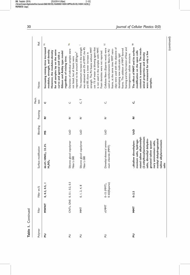
XML Template (2014) [25.8.2014–5:36pm] [1–32]//blrnas3/cenpro/ApplicationFiles/Journals/SAGE/3B2/CELJ/Vol00000/140041/APPFile/SG-CELJ140041.3d(CEL)[-PREPRINTER stage]
Tab
le1.
Continued
Poly
mer
Fille
rFi
ller
wt.%
Surf
ace
modifi
cation
Ble
ndin
gFo
amin
g
Mech
.
test
Note
sR
ef.
PU
MW
NT
0,
0.2
,0.5
,1
66.6
%H
NO
3:
33.3
%
H2S
O4
MS
Rf
CIn
cre
asi
ng
mix
ing
tim
ein
cre
ase
d
mo
du
lus,
stre
ngth
,an
dd
en
sity
.
Ho
wever,
the
mo
du
lus–
den
sity
for
all
sam
ple
sla
yo
nth
esa
me
cu
rve
an
dagre
ed
well
wit
ha
Gib
son
an
dA
shb
yty
pe
mo
del
regard
less
of
mix
ing
tim
e.
55
PU
CN
Ts,
GN
S0,0.1
,0.2
,0.3
Silic
one
glyc
olco
poly
mer
Nia
xL-5
80
UsD
Rf
CD
ensi
ties
of
indiv
idual
sam
ple
sw
ere
not
liste
d,but
allfo
ams
were
report
ed
tobe
around
200
kg/
m3
56
PU
MM
T0,1,2,4,8
Silic
one
glyc
olco
poly
mer
Nia
xL-5
80
UsD
Rf
C,
TT
he
max
imum
incr
eas
ein
the
stre
ngt
h
was
obta
ined
with
2%
ofM
MT,th
e4%
and
8%
show
alo
wer
incr
eas
ein
stre
ngt
h.T
he
PU
foam
sw
ithout
MM
T
use
1%
ofw
ater
asblo
win
gag
ent
that
isnot
use
din
the
sam
ple
sw
ith
MM
T.
Foam
densi
ties
were
not
report
ed.
1
PU
cf,M
MT
0–15
(MM
T),
0–65(E
spar
to)
Dim
eth
yl-d
iste
aryl
amm
o-
niu
mch
lori
de
(MM
T)
UsD
Rf
C,
Cellu
lose
fibers
(Esp
arto
wool)
were
use
das
rein
forc
em
ent
fibers
for
PU
foam
s,at
the
sam
etim
eM
MT
nan
o-
clay
sw
ere
use
dw
ith
the
obje
ctiv
eof
deve
lopin
gnew
multi-sc
ale
rigi
d
foam
s.T
he
additio
nof
MM
Tfa
vore
d
foam
ing
and
the
form
atio
noffin
er
and
hom
oge
neous
cellu
lar
stru
cture
.
57
PU
MM
T0–2.5
-,d
itallo
wd
imeth
yla
m-
mo
niu
msa
lts,
hyd
roge-
nate
dta
llo
walk
ylm
eth
yl-
(2-e
thylh
exyl)
am
mo
niu
m
salt
s,d
imeth
yl
dehyd
ro-
gen
ate
dta
llo
wq
uate
r-
nary
am
mo
niu
msa
lts,
meth
yl
dehyd
rogen
ate
d
tallo
walk
yla
mm
on
ium
salt
s
UsD
Rf
C,
Th
eeff
ect
ofM
MT
an
dit
ssu
rface
mo
dif
icati
on
on
the
op
en
cells
co
nte
nt
isexam
ined
.T
he
mech
-
an
ical
pro
pert
ies
an
dd
en
sity
were
measu
red
for
on
lya
few
sam
ple
s.
58
(continued)
30 Journal of Cellular Plastics 0(0)
ssingh
Cross-Out
ssingh
Replacement Text
39
ssingh
Cross-Out
ssingh
Replacement Text
87
ssingh
Cross-Out
ssingh
Replacement Text
88
ssingh
Cross-Out
ssingh
Replacement Text
89

XML Template (2014) [25.8.2014–5:36pm] [1–32]//blrnas3/cenpro/ApplicationFiles/Journals/SAGE/3B2/CELJ/Vol00000/140041/APPFile/SG-CELJ140041.3d(CEL)[-PREPRINTER stage]
Tab
le1.
Continued
Poly
mer
Fille
rFi
ller
wt.%
Surf
ace
modifi
cation
Ble
ndin
gFo
amin
g
Mech
.
test
Note
sR
ef.
PU
Cf,
MM
T0,1
-,m
eth
yldehyd
roge
nat
ed
tallo
wquat
ern
ary
amm
oniu
m
salt,m
eth
ylta
llow
bis
-2-
hydro
xye
thyl
,quat
ern
ary
amm
oniu
msa
lt
UsD
Rf
C59
PU
MM
T0,2
UsD
Rf
DM
AO
nly
afe
wsa
mple
sout
ofm
any
were
char
acte
rize
dm
ech
anic
ally
.
60
PU
MW
NT
0,0.1
Diff
ere
nt
surf
ace
modifi
cation,se
e
on
note
s
UsD
Rf
CT
he
CN
Ts
were
intr
oduce
din
am
ix-
ture
of
25%
HN
O3:75%
H2SO
4to
intr
oduce
carb
oxyl
groups
on
the
surf
ace;par
tof
those
nan
otu
bes
was
mix
ed
with
eth
ylenedia
min
eto
chan
ge
the
carb
oxyl
icgr
oups
into
amid
e
funct
ional
ity.
Als
opar
tof
the
nan
o-
tubes
was
intr
oduce
din
aso
lution
of
Fe2SO
4an
dH
2O
2to
obta
ina
hydro
-
xyl
funct
ional
ity.
The
densi
tyofth
ePU
foam
sw
as28
kg/
m3
and
the
densi
tyof
the
nan
oco
mposi
tefo
ams
was
betw
een
29
kg/
m3
and
32
kg/
m3,but
the
densi
tyof
the
foam
sw
asnot
report
ed
by
eve
ryty
pe.Fo
ams
were
not
mad
eusi
ng
unm
odifi
ed
CN
Ts.
61
PU
MM
T0,
3,
6,
9M
eth
yl-
tallo
w-b
is-
2-h
yd
roxyeth
yl
am
mo
niu
m(C
lois
ite
30B
),-(
Ben
ton
ite),
-(L
ap
on
ite
RD
)
UsD
Rf
CT
he
Clo
site
30B
,th
eo
nly
MM
T
wit
hsu
rface
mo
dif
icati
on
,h
as
the
hig
hest
mech
an
ical
incre
ase
of
all
MM
Tu
sed
.
62
PU
/PG
MM
T0,6
Meth
yl-t
allo
w-b
is-
2-h
ydro
xye
thyl
amm
oniu
m(C
lois
ite
30B
),-(
Bento
nite),
-(Lap
onite
RD
)
UsD
Rf
CT
he
soft
segm
ent
was
am
ixtu
reof
a
poly
eth
er
glyc
olan
da
poly
glyc
ero
lin
vari
ous
ratios
(0,35%
,an
d70%
poly
glyc
ero
l).
63
(continued)
Lobos and Velankar 31
ssingh
Cross-Out
ssingh
Replacement Text
90
ssingh
Cross-Out
ssingh
Replacement Text
91
ssingh
Cross-Out
ssingh
Replacement Text
92
ssingh
Cross-Out
ssingh
Replacement Text
49
ssingh
Cross-Out
ssingh
Replacement Text
93

XML Template (2014) [25.8.2014–5:36pm] [1–32]//blrnas3/cenpro/ApplicationFiles/Journals/SAGE/3B2/CELJ/Vol00000/140041/APPFile/SG-CELJ140041.3d(CEL)[-PREPRINTER stage]
Tab
le1.
Continued
Poly
mer
Fille
rFi
ller
wt.%
Surf
ace
modifi
cation
Ble
ndin
gFo
amin
g
Mech
.
test
Note
sR
ef.
PV
OH
PV
OH
MF
C0,
1,
3,
5–
insP
Ly
C64
Silic
one
Silic
on
eF
GS
,
CN
Ts
CN
Ts:
0,
0.1
,0.5
,1
FG
S:
0,
0.1
,
0.2
,0.2
5
(FG
S)
nit
ric
acid
;p
ota
s-
siu
mch
lora
te.
(CN
Ts)
-
UsD
Rf
CM
od
ulu
sin
cre
ase
dby
few
hu
n-
dre
dp
erc
en
tw
ith
the
ad
dit
ion
of
1%
CN
To
r0.2
5%
gra
ph
en
ew
ith
less
than
40%
incre
ase
info
am
den
sity
.S
ou
nd
ab
sorp
tio
no
fth
e
foam
sw
as
als
oevalu
ate
d.
6,2
5
Item
sin
bold
indic
ate
that
the
resu
lts
are
sum
mar
ized
inin
div
idual
dat
asheets
inth
eO
nlin
eSu
pple
menta
ryIn
form
atio
n.
32 Journal of Cellular Plastics 0(0)
ssingh
Cross-Out
ssingh
Replacement Text
94