Document name Title: Reconciliation of BCCS and WSM with ......System Model (WSM) that is used by...
16
Document name Title: Reconciliation of BCCS and WSM with Integrative Node-Breaker Method Category ( ) Regional Reliability Standard ( ) Regional Criteria ( ) Policy ( ) Guideline (X) Report or other ( ) Charter Document date November 13, 2014 Adopted/approved by TSS Date approved November 13, 2014 Custodian (entity responsible for maintenance and upkeep) SRWG Stored/filed Physical location: Web URL: https://www.wecc.biz/Reliability/Reconciliation_of_BCCS_a nd_WSM_with_Integrative_Node-Breaker_Method.pdf Previous name/number (if any) Status ( x) in effect ( ) usable, minor formatting/editing required ( ) modification needed ( ) superseded by _____________________ ( ) other _____________________________ ( ) obsolete/archived)
Transcript of Document name Title: Reconciliation of BCCS and WSM with ......System Model (WSM) that is used by...
Document name Title: Reconciliation of BCCS and WSM with Integrative Node-Breaker Method
Category ( ) Regional Reliability Standard ( ) Regional Criteria ( ) Policy ( ) Guideline (X) Report or other ( ) Charter
Document date November 13, 2014
Adopted/approved by TSS
Date approved November 13, 2014
Custodian (entity responsible for maintenance and upkeep)
SRWG
Stored/filed Physical location: Web URL: https://www.wecc.biz/Reliability/Reconciliation_of_BCCS_and_WSM_with_Integrative_Node-Breaker_Method.pdf
Previous name/number (if any)
Status ( x) in effect ( ) usable, minor formatting/editing required ( ) modification needed ( ) superseded by _____________________ ( ) other _____________________________ ( ) obsolete/archived)

W E S T E R N E L E C T R I C I T Y C O O R D I N A T I N G C O U N C I L
Reconciliation of BCCS and WSM with Integrative Node-Breaker Method
Node-Breaker Subgroup of the Modeling SPS and Relays Ad-Hoc Task Force (MSRATF)
November 13, 2014
155 North 400 West, Suite 200
Salt Lake City, Utah 84103-1114
Reconciliation of BCCS and WSM 1
W E S T E R N E L E C T R I C I T Y C O O R D I N A T I N G C O U N C I L
1. Overview
The Technical Studies Subcommittee (TSS) formed the Modeling SPS and Relays Ad-hoc Task Force (MSRATF) in August 2012 in response to findings and recommendations from the September 8, 2011 disturbance in the Pacific Southwest, and to achieve broad improvements in transparency between Transmission Owners (TO), Generator Owners (GO), Generator Operators (GOP), Transmission Operators (TOP), Transmission Planners (TP), Planning Coordinators (PC), and Reliability Coordinators (RC).
To aid in the effort of improving transparency, members of the Western Electricity Coordinating Council (WECC) and Peak Reliability would like to reconcile the WECC base cases with the West-wide System Model (WSM) that is used by Peak Reliability. The WSM is an Energy Management System (EMS) model of the form typically used in Real-time operations. The WECC base cases are power-flow models of the form typically used in system planning. Since both models represent much of the same physical equipment, reconciliation of the models should streamline the ability to make comparisons of WECC base cases and WSM cases, and allow validation of both cases by ensuring that a wider audience is using and examining the models.
Improvements that can be derived from comparing the WECC base cases with the WSM include; (1) understanding and resolving differences between cases, and (2) avoiding duplication of effort by mapping the current transient-stability models from WECC base cases into WSM snapshots. However, since each model includes details incompatible with the assumptions of the other model, some debate exists as to whether the models can be reconciled without loss of functionality in one model or the other (Figure 1).
Figure 1: WMS and WECC Base-case Data Intersections
The node-breaker modeling detail in the WSM, typical of EMS, is perceived as the significant barrier to reconciling the model. Refer to Node-Breaker Modeling in the Appendix for a detailed description. An

Reconciliation of BCCS and WSM 2
W E S T E R N E L E C T R I C I T Y C O O R D I N A T I N G C O U N C I L
equally significant challenge is presented by the different naming used by the two models. In this paper, when referencing node-breaker modeling, “names” refer to invariant identifiers of elements and are used to link the objects in the model to external functions including references in operating procedures, asset data and automated contingency files used in planning (Figure 2). Refer to Node-Breaker Element “Names” in the Appendix for additional details on “names.”
Figure 2: Links Between Intersecting Data and Related Non-intersecting Data
The purpose of this paper is to outline a method that could be used to move the WECC base cases toward the node-breaker model. The method of incorporating node-breaker connectivity models in WECC base cases being proposed by the MSRATF in this paper is what was being called the hybrid method, and now is more accurately called the integrative method. This method transitions from the current bus-branch model to a node-breaker representation by enhancing sections of the bus-branch model (i.e., adding node-breaker modeling detail to bus-branch representation). Inserting the breaker-node models in a substation-by-substation approach will take a significant amount of time to fully populate the entire WECC base-case model with node-breaker model representation. This proposal is a transition from the suggestion made in the previous paper (“Node-Breaker White Paper” dated January 22, 2014).
The Node Breaker White Paper originally proposed reconciling the two models by replacing the base topology for WECC base cases with node-breaker topology exported from the WSM. This paper presents a refinement on that proposal using an integrative approach (called integrative method in this paper) that imports the node-breaker modeling used in the WSM into the WECC base cases while preserving the existing WECC base-case naming, which is essential to existing dynamic data files and automation files.

Reconciliation of BCCS and WSM 3
W E S T E R N E L E C T R I C I T Y C O O R D I N A T I N G C O U N C I L
2. Why Use An Integrative Method
Several shortcomings of the full-replacement approach were identified with further analysis, related to both loss of functionality (Figure 3) and procedural limitations.
Figure 3: Planning Loss of Functionality from Replacement Approach
The major shortcomings with full-replacement that are driving the recommended integrative approach are:
• Data sharing concerns; the WSM data is restricted under a non-disclosure agreement that many users of WECC base cases are not able to sign as it would impose untenable limits on what WECC base cases could be used for and to whom they could be distributed.
• Switching to an integrative method puts the responsibility of updating and maintaining the models in the hands of the data owners. It is the responsibility of the data owners to update and maintain their models in accordance with the Data Preparation Manual. A full or partial insertion of node-breaker (connectivity) data in the system can be done to the extent that the data owners agree to the change; however, the owners will continue to be responsible for the accuracy of the models of their equipment.
• Data that is important to the planning community and maintained in the bus-branch models would be lost through a full replacement with the WSM model. This includes the topological data currently in the bus-branch representation. The integrative method allows TOs to keep their topological representation of substation buses while inserting detailed connectivity data for each bus, such as bus arrangement and bus segments, branch connection, breakers and switches.
• Descriptions of contingencies can be given in bus-branch format or as a label (a branch label, bus segment label, etc.), or by specifying the breakers to open. The system simulation

Reconciliation of BCCS and WSM 4
W E S T E R N E L E C T R I C I T Y C O O R D I N A T I N G C O U N C I L
software will need to support this by retaining bus-branch data and linking breaker-node data to it. The desire to retain static identifiers for Topological Nodes (or buses) may be a transitional desire. In the long term, MSRATF would recommend that engineers reference elements using a label of the element itself instead of using static bus identifiers as an identifier of other elements. This is described in further detail below, and in Power Flow Program Capabilities in the Appendix.
• Intentional modeling differences such as systems that are represented as reduced, equivalent systems in WSM cases would need to be identified and expanded if the WSM model were used as the starting point.
For similar reasons, the approach of reconciling the two models by overwriting WSM data with the WECC base-case model is also not recommended. The desired solution is one that preserves the detail from both models, and maintains the familiarity and the functionality of both models for the uses to which both planning staff and Real-time staff will put them. This is an "integrative" approach to implementing a common model, rather than a "replacement" approach.
3. The Integrative Method
3.1. Topological Nodes and Connectivity Nodes
Critical to an integrative approach is the realization that what the planning tools call "buses" are a fundamentally different class of object from what the EMS tools call "buses" or "nodes." The common information model (CIM) recognizes this and refers to the two different objects as "Topological Nodes" and "Connectivity Nodes" respectively.
EMS systems that use the International Electrotechnical Commission (IEC) Common Information Model Standard 61970 Edition 3 already distinguish Connectivity Nodes from Topological Nodes and support a containment relationship between them, where any Topological Node must contain one or more Connectivity Nodes; and a Topological Node is a type of “Identified Object” with a permanent non-volatile name and description. Connectivity Nodes may be contained only by zero or one Topological Node. An example of how Topological Nodes and Connectivity Nodes are used can be found in the Example section of the Appendix.
Even legacy EMS systems already recognize the distinction between Topological Nodes and Connectivity Nodes, and may include among their network applications a "topology processor" capable of merging all the nodes that are joined by closed zero-impedance devices into a single Topological Node equivalent to a planning "bus." A shortcoming of legacy EMS systems is that they apply arbitrary bus numbers to the topology that they produce and these bus numbers change since switching devices that are in their non-normal state create new Topological Node arrangements. That shortcoming is overcome by more recent Topology processors that assign a non-volatile name to any Topological

Reconciliation of BCCS and WSM 5
W E S T E R N E L E C T R I C I T Y C O O R D I N A T I N G C O U N C I L
Node that is in its normal configuration, and use a specified range of unassigned identifiers for Topological Nodes resulting from abnormal switching states. Vendors of EMS software must, if they have not already done so, implement the ability to specify a non-volatile persistent association between Connectivity Nodes and those Topological Nodes represented under normal system conditions.
Vendors of planning tool software must also implement Connectivity Nodes as a separate class of object from “buses.” The technique of flagging zero-impedance branches to represent breakers and switches, and creating bus numbers as Connectivity Nodes (grouping buses together implicitly into Topological Node groupings), does not meet all the desires of integrative modeling as described in Section 2.
For this reason, to aid in the transition to these new models, Power flow software vendors are asked to provide a mechanism of maintaining static identifiers for Topological Nodes. In addition, some mechanism for designating the difference between a transmission element (line, transformer, or series reactor/capacitor) and a switching device (breaker, disconnect, fuse, load break disconnect, jumper, etc.) will be necessary. Also MSRATF recommends that software vendors provide the ability to view system diagrams using either Connectivity Node detail or the higher-level Topological Node layout. In the short term, the ability to continue defining contingencies using syntax that uses Topological Node’s static identifiers (such as bus numbers) should be maintained. In the long term, MSRATF highly encourages that the syntax is switched to using element labels instead.
3.2. Building Models With An Integrative Method
The integrative method continues the status quo of having two models maintained, the WECC base case model and the WSM. However, the WECC base case model can be built to include the one-to-many containment relationship of Topological Nodes and Connectivity Nodes. In the immediate term, this allows users of the WECC base case to continue using the syntax that uses Topological Node identifiers (such as a bus numbers) to refer to elements in the system (generators, transformers, etc.). However, the WECC base case will be augmented to include the labels used in the WSM model as well, thus enabling the engineering community to start using these identifiers themselves or, at the very least, pass data back to the maintainers of the WSM model using the identifiers that are used in the WSM model. With these software requirements implemented, the integrative model-reconciliation process would comprise the following actions:
1. Owners of planning data who submit updates to the WECC Base Case Coordination System (BCCS) will begin to enter Connectivity Nodes, and switches into their planning models, using connectivity-node names, switch-names, and node-breaker topology from the WSM. These data will be entered gradually, over time, and consistent with a realistic schedule to be defined between PEAK and WECC, recognizing the other demands on planning and staff's
Reconciliation of BCCS and WSM 6
W E S T E R N E L E C T R I C I T Y C O O R D I N A T I N G C O U N C I L
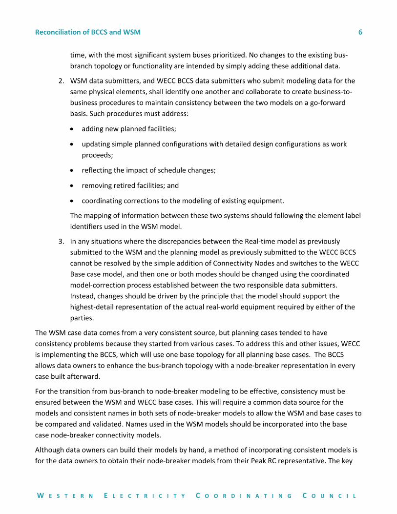
time, with the most significant system buses prioritized. No changes to the existing bus-branch topology or functionality are intended by simply adding these additional data.
2. WSM data submitters, and WECC BCCS data submitters who submit modeling data for the same physical elements, shall identify one another and collaborate to create business-to-business procedures to maintain consistency between the two models on a go-forward basis. Such procedures must address:
• adding new planned facilities;
• updating simple planned configurations with detailed design configurations as work proceeds;
• reflecting the impact of schedule changes;
• removing retired facilities; and
• coordinating corrections to the modeling of existing equipment.
The mapping of information between these two systems should following the element label identifiers used in the WSM model.
3. In any situations where the discrepancies between the Real-time model as previously submitted to the WSM and the planning model as previously submitted to the WECC BCCS cannot be resolved by the simple addition of Connectivity Nodes and switches to the WECC Base case model, and then one or both modes should be changed using the coordinated model-correction process established between the two responsible data submitters. Instead, changes should be driven by the principle that the model should support the highest-detail representation of the actual real-world equipment required by either of the parties.
The WSM case data comes from a very consistent source, but planning cases tended to have consistency problems because they started from various cases. To address this and other issues, WECC is implementing the BCCS, which will use one base topology for all planning base cases. The BCCS allows data owners to enhance the bus-branch topology with a node-breaker representation in every case built afterward.
For the transition from bus-branch to node-breaker modeling to be effective, consistency must be ensured between the WSM and WECC base cases. This will require a common data source for the models and consistent names in both sets of node-breaker models to allow the WSM and base cases to be compared and validated. Names used in the WSM models should be incorporated into the base case node-breaker connectivity models.
Although data owners can build their models by hand, a method of incorporating consistent models is for the data owners to obtain their node-breaker models from their Peak RC representative. The key
Reconciliation of BCCS and WSM 7
W E S T E R N E L E C T R I C I T Y C O O R D I N A T I N G C O U N C I L
aspect of this process is that the incorporated models will be compared to the WSM models and any differences will need to be rectified.
3.3. Maintaining Models With The Integrative Method
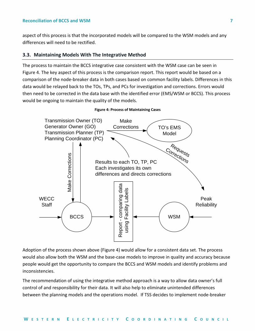
The process to maintain the BCCS integrative case consistent with the WSM case can be seen in Figure 4. The key aspect of this process is the comparison report. This report would be based on a comparison of the node-breaker data in both cases based on common facility labels. Differences in this data would be relayed back to the TOs, TPs, and PCs for investigation and corrections. Errors would then need to be corrected in the data base with the identified error (EMS/WSM or BCCS). This process would be ongoing to maintain the quality of the models.
Figure 4: Process of Maintaining Cases
Transmission Owner (TO)Generator Owner (GO)Transmission Planner (TP)Planning Coordinator (PC)
BCCS
Rep
ort -
com
parin
g da
ta
usin
g Fa
cilit
y La
bels
Results to each TO, TP, PCEach investigates its own differences and directs corrections
Mak
e C
orre
ctio
ns
WECCStaff
PeakReliability
RequestsCorrections
WSM
TO’s EMS Model
MakeCorrections
Adoption of the process shown above (Figure 4) would allow for a consistent data set. The process would also allow both the WSM and the base-case models to improve in quality and accuracy because people would get the opportunity to compare the BCCS and WSM models and identify problems and inconsistencies.
The recommendation of using the integrative method approach is a way to allow data owner’s full control of and responsibility for their data. It will also help to eliminate unintended differences between the planning models and the operations model. If TSS decides to implement node-breaker

Reconciliation of BCCS and WSM 8
W E S T E R N E L E C T R I C I T Y C O O R D I N A T I N G C O U N C I L
topology in WECC planning models, then SRWG should define a realistic schedule over which full integration is to be completed.
Reconciliation of BCCS and WSM 1
W E S T E R N E L E C T R I C I T Y C O O R D I N A T I N G C O U N C I L
Appendix
Node-Breaker Modeling
Currently, the majority of off-line planning studies are using bus-branch models to represent power system networks. These models typically represent each substation with a single bus at each nominal voltage level (topological modeling). Without knowledge obtained outside the represented bus-branch model it is not possible to determine the substation-breaker configuration and how it operates during contingencies. The lack of breaker information requires that a large number of contingencies must be manually created to replicate bus contingencies and breaker failure contingencies. This manual effort often presents an opportunity for human error to occur and takes a lot of time to reconfigure buses for study work.
A solution to this is to insert node-breaker (connectivity) models to amend the simplified bus models in the bus-branch configuration. Node-breaker models can provide a fully built out substation representation (i.e., elements such as breakers, switches, branches, shunts, etc. are modeled individually and connected via Connectivity Nodes). These models provide several advantages over the simplified bus-branch models including, but not limited to:
• Providing improved visibility of substation configurations and equipment.
• Showing case-specific switch and breaker statuses.
• Providing enough information for power flow programs to fully automate the creation and processing of contingencies. An example would be to enable automatic inclusion of stuck-breaker contingencies.
• Simplifying the modeling and simulation of protection system operations.
• Allowing the use of compatible data sets for operational studies and planning studies when representing existing topology.
• Assisting in model validation from PMU data and system disturbances.
• Allowing for easy and smooth representation of topology changes within substations by changing the status of switching devices (e.g., bus splitting).
Common tower and common corridor outages would continue to need to be inserted manually.
Node-Breaker Element “Names”
Names are invariant identifiers of elements in node-breaker models and are derived in the Peak Reliability EMS for use in WSM cases by splicing together facility attributes that include node names, voltage(s), facility type, facility number, areas, zones and owners. Bus numbers are not used as bus

Reconciliation of BCCS and WSM 2
W E S T E R N E L E C T R I C I T Y C O O R D I N A T I N G C O U N C I L
identifiers in EMS and the WSM. Also, WSM cases include bus segments, breakers and switches whereas the WECC planning cases do not include them, yet. The node names, area numbers, and owner numbers that Peak Reliability uses and maintains are usually not the same as those used in WECC planning cases. So while the names in the WSM are derived from EMS facility attributes the same names cannot be derived from attributes in the planning cases because the attributes used are different.
In the BCCS, facility attributes in connectivity modeling will be assigned and maintained by the TO/GO/TP for existing and future facilities. This includes descriptive attributes such as bus names and numbers, planning areas, zones and owners. To map facilities between BCCS planning cases and WSM cases, the WSM facility labels will be inserted by the TO/GO/TPs as a facility attribute for their facilities in the WECC planning cases.
Power Flow Program Capabilities
Below are some of the basic capabilities needed by the power flow programs commonly used in WECC for node-breaker modeling:
• The system simulation software will need to support this by retaining bus-branch data and linking node-breaker data to it.
• Ability to automatically produce one-line views of bus and breaker configurations at substations by a bus voltage level (topological representation).
• Ability to specify a node-breaker or a bus-branch one-line view of the data and solution.
• Graphical User Interface (GUI) designed for building node-breaker substation representations using drag-and-drop capabilities to insert bus components like breakers and switches.
• Connectivity processing:
o Ability to determine which breakers are needed to isolate a given element or group of elements under a common protection system.
o Automated contingency analysis that identifies each of the possible element outage scenarios for a given class of contingencies (such as stuck breakers) using the node-breaker information.
• Capability of applying node-breaker representations on a station-by-station basis.
• Ability to create an equivalent bus-branch topological representation from node-breaker connectivity detail, for individual station buses.
• Added detail should not significantly increase solution processing time.
Reconciliation of BCCS and WSM 3
W E S T E R N E L E C T R I C I T Y C O O R D I N A T I N G C O U N C I L
• Existing models should continue to appropriately model equipment; the added detail should not negatively affect accuracy of the solution/model.
Some of the major power flow programs already have some of the above-mentioned capabilities.
Example
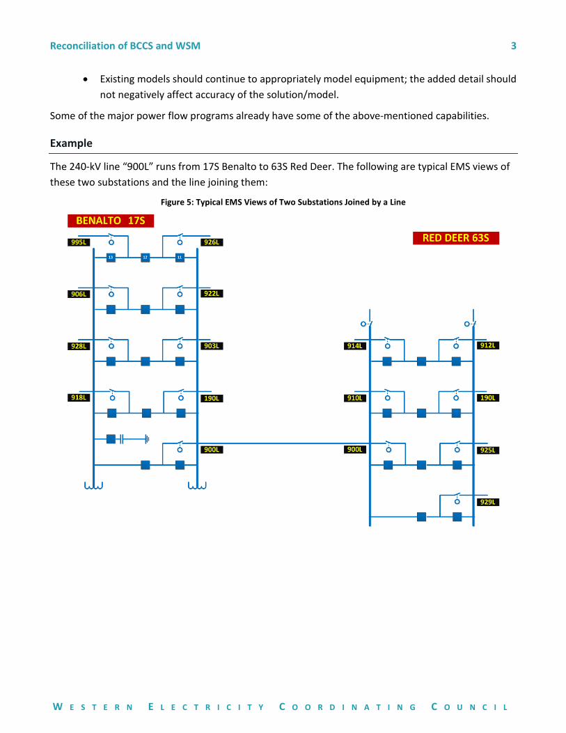
The 240-kV line “900L” runs from 17S Benalto to 63S Red Deer. The following are typical EMS views of these two substations and the line joining them:
Figure 5: Typical EMS Views of Two Substations Joined by a Line
Reconciliation of BCCS and WSM 4
W E S T E R N E L E C T R I C I T Y C O O R D I N A T I N G C O U N C I L
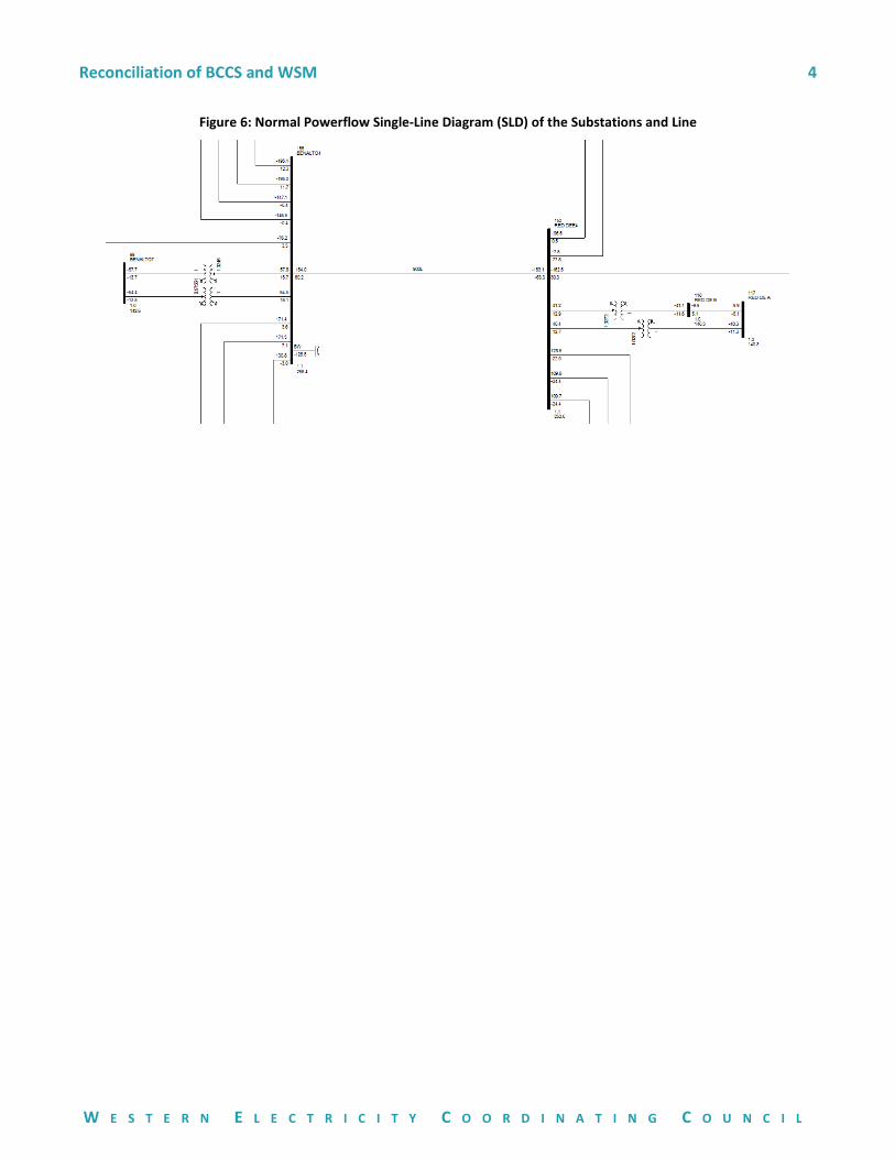
Figure 6: Normal Powerflow Single-Line Diagram (SLD) of the Substations and Line

Reconciliation of BCCS and WSM 5
W E S T E R N E L E C T R I C I T Y C O O R D I N A T I N G C O U N C I L
An older "GEXM" view (from PSS/E1 version 26) of bus 155 can be used to reinforce the understanding of Topological Nodes (i.e., planning buses) as a container:
Figure 7: "GEXM" view of bus 155
1 Power System Simulator for Engineering.

Reconciliation of BCCS and WSM 6
W E S T E R N E L E C T R I C I T Y C O O R D I N A T I N G C O U N C I L
Node-breaker data integrated into the traditional (bus 155) bus-branch data:
Figure 8: Bus 155 with Node-breaker Data
The traditional bus configuration still exists. Contingencies can still be defined using “frombus-tobus-ckt” notation, so contingency files that were created manually can still be used. However, MSRATF would request that the models also be augmented to allow the specification of label identifiers for a branch to make the future migration away from the use of these bus identifiers easier. New contingency definitions can be created by examining which breakers must trip to clear a fault and what the clearing times of those breakers are, and that new functionality comes with no loss of existing functionality. Of course, to realize that additional functionality throughout the system, integration of the breaker-node topology into the bus-branch topology must be completed.