DM Section 1A Turnpike Geometric Design Rev 9-2010€¦ · NJTA Design Manual New Jersey Turnpike...
49
NJTA Design Manual New Jersey Turnpike Geometric Design May 2007 Revised August 2010 SECTION 1A NEW JERSEY TURNPIKE GEOMETRIC DESIGN Table of Contents Page No 1A.1 GENERAL .................................................................................................................1 1A.1.1 DESIGN CONTROLS..........................................................................................1 1A.2 MAINLINE ROADWAYS ...........................................................................................4 1A.2.1 ROADWAY DESIGNATION ..................................................................................4 1A.2.2 DESIGN SPEED ................................................................................................4 1A.2.3 STOPPING SIGHT DISTANCE .............................................................................4 1A.2.4 HORIZONTAL ALIGNMENT..................................................................................4 1A.2.5 SUPERELEVATION ............................................................................................5 1A.2.6 VERTICAL ALIGNMENT ......................................................................................8 1A.2.7 PAVEMENT ......................................................................................................9 1A.2.8 TYPICAL SECTION ..........................................................................................14 1A.2.9 DETOURS ......................................................................................................20 1A.3 INTERCHANGE RAMPS.........................................................................................21 1A.3.1 ROADWAY DESIGNATION ................................................................................21 1A.3.2 DESIGN SPEED ..............................................................................................21 1A.3.3 STOPPING SIGHT DISTANCE ...........................................................................22 1A.3.4 HORIZONTAL ALIGNMENT................................................................................22 1A.3.5 SUPERELEVATION ..........................................................................................24 1A.3.6 VERTICAL ALIGNMENT ....................................................................................26 1A.3.7 PAVEMENT ....................................................................................................27 1A.3.8 TYPICAL SECTION ..........................................................................................27 1A.3.9 DETOURS ......................................................................................................30 1A.4 AUXILIARY LANES ................................................................................................31 1A.4.1 ACCELERATION LANES ...................................................................................31 1A.4.2 DECELERATION LANES ...................................................................................33 1A.4.3 CLIMBING LANES............................................................................................37 1A.5 OTHER ROADWAYS ..............................................................................................37 1A.5.1 CROSSROADS................................................................................................37 1A.5.2 ACCESS AND SERVICE ROADS ........................................................................37 1A.5.3 U-TURNS.......................................................................................................38
Transcript of DM Section 1A Turnpike Geometric Design Rev 9-2010€¦ · NJTA Design Manual New Jersey Turnpike...

NJTA Design Manual New Jersey Turnpike Geometric Design
May 2007 Revised August 2010
SECTION 1A NEW JERSEY TURNPIKE GEOMETRIC DESIGN
Table of Contents
Page No 1A.1 GENERAL .................................................................................................................1
1A.1.1 DESIGN CONTROLS ..........................................................................................1
1A.2 MAINLINE ROADWAYS ...........................................................................................4
1A.2.1 ROADWAY DESIGNATION ..................................................................................4
1A.2.2 DESIGN SPEED ................................................................................................4
1A.2.3 STOPPING SIGHT DISTANCE .............................................................................4
1A.2.4 HORIZONTAL ALIGNMENT..................................................................................4
1A.2.5 SUPERELEVATION ............................................................................................5
1A.2.6 VERTICAL ALIGNMENT ......................................................................................8
1A.2.7 PAVEMENT ......................................................................................................9
1A.2.8 TYPICAL SECTION ..........................................................................................14
1A.2.9 DETOURS ......................................................................................................20
1A.3 INTERCHANGE RAMPS .........................................................................................21
1A.3.1 ROADWAY DESIGNATION ................................................................................21
1A.3.2 DESIGN SPEED ..............................................................................................21
1A.3.3 STOPPING SIGHT DISTANCE ...........................................................................22
1A.3.4 HORIZONTAL ALIGNMENT................................................................................22
1A.3.5 SUPERELEVATION ..........................................................................................24
1A.3.6 VERTICAL ALIGNMENT ....................................................................................26
1A.3.7 PAVEMENT ....................................................................................................27
1A.3.8 TYPICAL SECTION ..........................................................................................27
1A.3.9 DETOURS ......................................................................................................30
1A.4 AUXILIARY LANES ................................................................................................31
1A.4.1 ACCELERATION LANES ...................................................................................31
1A.4.2 DECELERATION LANES ...................................................................................33
1A.4.3 CLIMBING LANES ............................................................................................37
1A.5 OTHER ROADWAYS ..............................................................................................37
1A.5.1 CROSSROADS ................................................................................................37
1A.5.2 ACCESS AND SERVICE ROADS ........................................................................37
1A.5.3 U-TURNS.......................................................................................................38

NJTA Design Manual New Jersey Turnpike Geometric Design
May 2007 Revised August 2010
1A.5.4 Z-TURNS ....................................................................................................... 41
1A.6 GRADING CRITERIA .............................................................................................. 42
1A.7 FENCING ................................................................................................................ 44
List of Exhibits
Page No Exhibit 1A - 1 WB-67 (Interstate Semi-Trailer) Design Vehicle ............................................. 2
Exhibit 1A - 2 Components for Determining Horizontal Sight Distance ................................. 3
Exhibit 1A - 3 Minimum Stopping Sight Distance for Mainline Roadways ............................. 4
Exhibit 1A - 4 Minimum Mainline Roadway Radii for Design Superelevation Rates, emax= 5% ............................................................................................. 6
Exhibit 1A - 5 Maximum Relative Gradient (Mainline) ........................................................... 7
Exhibit 1A - 6 Adjustment Factor for Number of Lanes Rotated ........................................... 7
Exhibit 1A - 7 Location of Superelevation Runoff (Mainline) ................................................. 8
Exhibit 1A - 8 Design Controls for Mainline Roadway Vertical Curves .................................. 9
Exhibit 1A - 9 Turnpike Pavement (Mainline, ramp & Shoulders) ....................................... 10
Exhibit 1A - 10 Pavement Removal and Reconstruction Detail .......................................... 11
Exhibit 1A - 11 Longitudinal Pavement Stepping Detail ...................................................... 11
Exhibit 1A - 12 Transverse Pavement Stepping Detail ....................................................... 12
Exhibit 1A - 13 New Pavement Interface with Existing Pavement....................................... 13
Exhibit 1A - 14 Toll Plaza Pavement Interface.................................................................... 13
Exhibit 1A - 15 Mainline Roadway Typical Sections (Normal Sections) .............................. 15
Exhibit 1A - 16 Mainline Roadway Typical Sections (Superelevated Sections) ................... 16
Exhibit 1A - 17 Center Median Typical Sections ................................................................. 17
Exhibit 1A - 18 Inner-Outer Median Typical Sections (10 - 12 Lanes) ................................ 18
Exhibit 1A - 19 Inner-Outer Median Typical Sections (14 Lanes)........................................ 19
Exhibit 1A - 20 Lateral Bridge Clearances - Mainline.......................................................... 20
Exhibit 1A - 21 Minimum Curve Radii for Ramp Design Speed .......................................... 22
Exhibit 1A - 22 Minimum Stopping Sight Distance for Interchange Ramps ......................... 22
Exhibit 1A - 23 Interchange Ramp Geometry ..................................................................... 23
Exhibit 1A - 24 Minimum Interchange Ramp Lane Width by Radii ...................................... 24
Exhibit 1A - 25 Minimum Interchange Ramp Radii for Design Superelevation Rates, emax= 6% ........................................................................................... 25
Exhibit 1A - 26 Maximum Relative Gradient (Interchange Ramp) ....................................... 26
Exhibit 1A - 27 Location of Superelevation Runoff (Interchange Ramps) ........................... 26
NJTA Design Manual New Jersey Turnpike Geometric Design
May 2007 Revised August 2010
Exhibit 1A - 28 Design Controls for Interchange Ramp Vertical Curves ..............................27
Exhibit 1A - 29 Interchange Ramp Typical Sections ...........................................................28
Exhibit 1A - 30 Interchange Ramp Curb Sections and Details ............................................29
Exhibit 1A - 31 Lateral Bridge Clearances - Ramps ............................................................30
Exhibit 1A - 32 Ramp Acceleration Lane Geometry ............................................................32
Exhibit 1A - 33 Minimum Length of Acceleration Lane ........................................................32
Exhibit 1A - 34 Acceleration Lane Grade Adjustment Factors ............................................32
Exhibit 1A - 35 Two-Lane Entrance Ramp ..........................................................................33
Exhibit 1A - 36 Ramp Deceleration Lane Geometry ...........................................................34
Exhibit 1A - 37 Two-Lane Exit Ramp ..................................................................................35
Exhibit 1A - 38 Lane Drop Configuration ............................................................................36
Exhibit 1A - 39 Typical Nose Grading .................................................................................37
Exhibit 1A - 40 Car Parking Pavement Section ...................................................................38
Exhibit 1A - 41 U-Turn Geometric Criteria ..........................................................................39
Exhibit 1A - 42 U-Turn Pavement Section ..........................................................................39
Exhibit 1A - 43 U-Turn Typical Sections .............................................................................40
Exhibit 1A - 44 Z-Turn Geometric Criteria ...........................................................................41
Exhibit 1A - 45 Turnpike Grading Criteria ...........................................................................43
Exhibit 1A - 46 Stream Fencing Criteria ..............................................................................45

NJTA Design Manual New Jersey Turnpike Geometric Design
May 2007 1A - 1 Revised March 2014
SECTION 1A NEW JERSEY TURNPIKE GEOMETRIC DESIGN
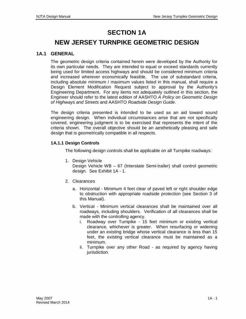
1A.1 GENERAL The geometric design criteria contained herein were developed by the Authority for its own particular needs. They are intended to equal or exceed standards currently being used for limited access highways and should be considered minimum criteria and increased wherever economically feasible. The use of substandard criteria, including absolute minimum / maximum values listed in this manual, shall require a Design Element Modification Request subject to approval by the Authority’s Engineering Department. For any items not adequately outlined in this section, the Engineer should refer to the latest edition of AASHTO A Policy on Geometric Design of Highways and Streets and AASHTO Roadside Design Guide. The design criteria presented is intended to be used as an aid toward sound engineering design. When individual circumstances arise that are not specifically covered, engineering judgment is to be exercised that represents the intent of the criteria shown. The overall objective should be an aesthetically pleasing and safe design that is geometrically compatible in all respects.
1A.1.1 Design Controls
The following design controls shall be applicable on all Turnpike roadways:
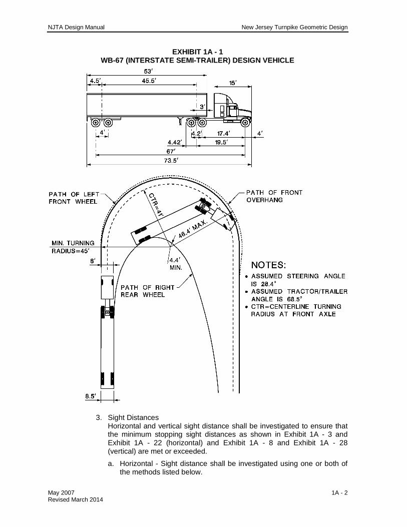
1. Design Vehicle Design Vehicle WB – 67 (Interstate Semi-trailer) shall control geometric design. See Exhibit 1A - 1.
2. Clearances
a. Horizontal - Minimum 4 feet clear of paved left or right shoulder edge to obstruction with appropriate roadside protection (see Section 3 of this Manual).
b. Vertical - Minimum vertical clearances shall be maintained over all roadways, including shoulders. Verification of all clearances shall be made with the controlling agency. i. Roadway over Turnpike - 15 feet minimum or existing vertical
clearance, whichever is greater. When resurfacing or widening under an existing bridge whose vertical clearance is less than 15 feet, the existing vertical clearance must be maintained as a minimum.
ii. Turnpike over any other Road - as required by agency having jurisdiction.
NJTA Design Manual New Jersey Turnpike Geometric Design
May 2007 1A - 2 Revised March 2014
EXHIBIT 1A - 1 WB-67 (INTERSTATE SEMI-TRAILER) DESIGN VEHICLE
3. Sight Distances Horizontal and vertical sight distance shall be investigated to ensure that the minimum stopping sight distances as shown in Exhibit 1A - 3 and Exhibit 1A - 22 (horizontal) and Exhibit 1A - 8 and Exhibit 1A - 28 (vertical) are met or exceeded.
a. Horizontal - Sight distance shall be investigated using one or both of the methods listed below.

NJTA Design Manual New Jersey Turnpike Geometric Design
May 2007 1A - 3 Revised March 2014
i. Where obstruction and vehicle are located within the limits of a simple curve:
22 )2( sRRHSO
Where: s = Stopping sight distance, ft R = Radius of curve, ft HSO = Horizontal sightline offset, ft
ii. Where the vehicle, the obstruction, or both are situated beyond
the limits of a simple curve or within the limits of a compound curve, the design should be checked by utilizing graphical procedures.
b. Vertical - The sight distance for crest curves shall be based on a height of eye of 3.5 feet to an object 6 inches high. The sight distance for sag curves shall be based on headlight sight distance using a headlight height of 2.0 feet and a 1-degree upward divergence of the light beam from the longitudinal axis of the vehicle.
EXHIBIT 1A - 2 COMPONENTS FOR DETERMINING HORIZONTAL SIGHT DISTANCE
NJTA Design Manual New Jersey Turnpike Geometric Design
May 2007 1A - 4 Revised March 2014
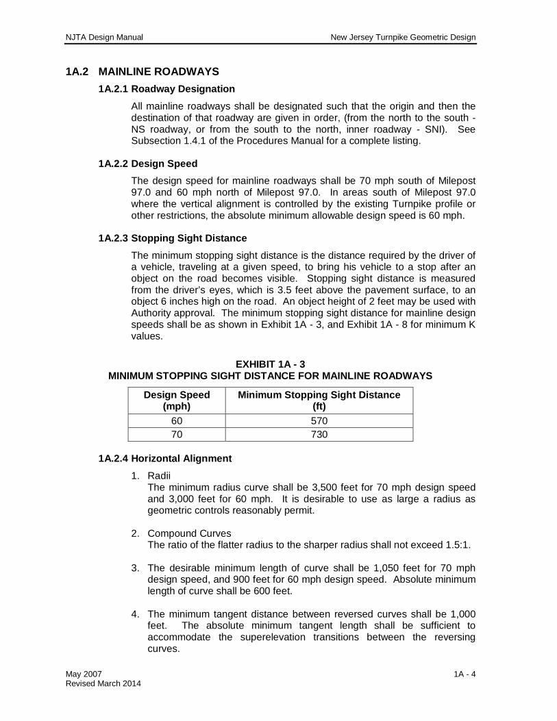
1A.2 MAINLINE ROADWAYS 1A.2.1 Roadway Designation
All mainline roadways shall be designated such that the origin and then the destination of that roadway are given in order, (from the north to the south - NS roadway, or from the south to the north, inner roadway - SNI). See Subsection 1.4.1 of the Procedures Manual for a complete listing.
1A.2.2 Design Speed The design speed for mainline roadways shall be 70 mph south of Milepost 97.0 and 60 mph north of Milepost 97.0. In areas south of Milepost 97.0 where the vertical alignment is controlled by the existing Turnpike profile or other restrictions, the absolute minimum allowable design speed is 60 mph.
1A.2.3 Stopping Sight Distance
The minimum stopping sight distance is the distance required by the driver of a vehicle, traveling at a given speed, to bring his vehicle to a stop after an object on the road becomes visible. Stopping sight distance is measured from the driver’s eyes, which is 3.5 feet above the pavement surface, to an object 6 inches high on the road. An object height of 2 feet may be used with Authority approval. The minimum stopping sight distance for mainline design speeds shall be as shown in Exhibit 1A - 3, and Exhibit 1A - 8 for minimum K values.
EXHIBIT 1A - 3 MINIMUM STOPPING SIGHT DISTANCE FOR MAINLINE ROADWAYS
Design Speed (mph)
Minimum Stopping Sight Distance (ft)
60 570 70 730
1A.2.4 Horizontal Alignment
1. Radii The minimum radius curve shall be 3,500 feet for 70 mph design speed and 3,000 feet for 60 mph. It is desirable to use as large a radius as geometric controls reasonably permit.
2. Compound Curves
The ratio of the flatter radius to the sharper radius shall not exceed 1.5:1. 3. The desirable minimum length of curve shall be 1,050 feet for 70 mph
design speed, and 900 feet for 60 mph design speed. Absolute minimum length of curve shall be 600 feet.
4. The minimum tangent distance between reversed curves shall be 1,000
feet. The absolute minimum tangent length shall be sufficient to accommodate the superelevation transitions between the reversing curves.
NJTA Design Manual New Jersey Turnpike Geometric Design
May 2007 1A - 5 Revised March 2014
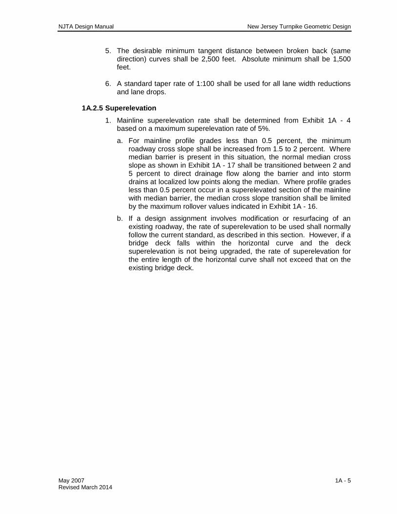
5. The desirable minimum tangent distance between broken back (same direction) curves shall be 2,500 feet. Absolute minimum shall be 1,500 feet.
6. A standard taper rate of 1:100 shall be used for all lane width reductions
and lane drops.
1A.2.5 Superelevation 1. Mainline superelevation rate shall be determined from Exhibit 1A - 4
based on a maximum superelevation rate of 5%.
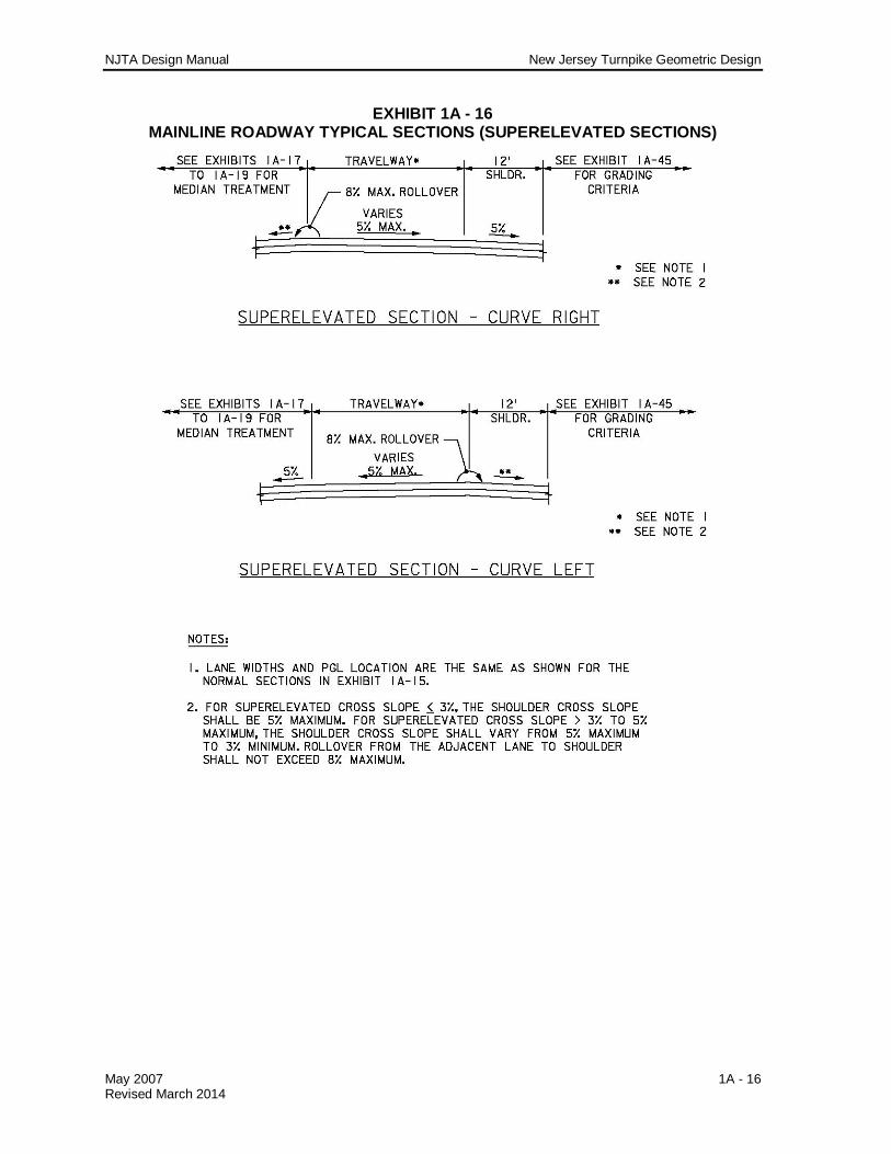
a. For mainline profile grades less than 0.5 percent, the minimum roadway cross slope shall be increased from 1.5 to 2 percent. Where median barrier is present in this situation, the normal median cross slope as shown in Exhibit 1A - 17 shall be transitioned between 2 and 5 percent to direct drainage flow along the barrier and into storm drains at localized low points along the median. Where profile grades less than 0.5 percent occur in a superelevated section of the mainline with median barrier, the median cross slope transition shall be limited by the maximum rollover values indicated in Exhibit 1A - 16.
b. If a design assignment involves modification or resurfacing of an existing roadway, the rate of superelevation to be used shall normally follow the current standard, as described in this section. However, if a bridge deck falls within the horizontal curve and the deck superelevation is not being upgraded, the rate of superelevation for the entire length of the horizontal curve shall not exceed that on the existing bridge deck.
NJTA Design Manual New Jersey Turnpike Geometric Design
May 2007 1A - 6 Revised March 2014
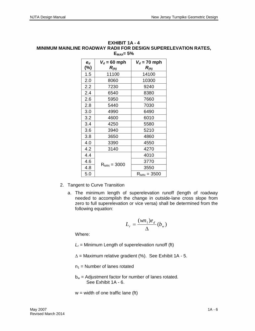
EXHIBIT 1A - 4 MINIMUM MAINLINE ROADWAY RADII FOR DESIGN SUPERELEVATION RATES,
EMAX= 5%
ed (%)
Vd = 60 mph R(ft)
Vd = 70 mph R(ft)
1.5 11100 14100 2.0 8060 10300 2.2 7230 9240 2.4 6540 8380 2.6 5950 7660 2.8 5440 7030 3.0 4990 6490 3.2 4600 6010 3.4 4250 5580 3.6 3940 5210 3.8 3650 4860 4.0 3390 4550 4.2 3140 4270 4.4
RMIN = 3000
4010 4.6 3770 4.8 3550 5.0 RMIN = 3500
2. Tangent to Curve Transition
a. The minimum length of superelevation runoff (length of roadway needed to accomplish the change in outside-lane cross slope from zero to full superelevation or vice versa) shall be determined from the following equation:
)()( 1
wd
r bewn
L
Where: Lr = Minimum Length of superelevation runoff (ft) = Maximum relative gradient (%). See Exhibit 1A - 5. n1 = Number of lanes rotated bw = Adjustment factor for number of lanes rotated.
See Exhibit 1A - 6. w = width of one traffic lane (ft)
NJTA Design Manual New Jersey Turnpike Geometric Design
May 2007 1A - 7 Revised March 2014
ed = design superelevation rate (%)
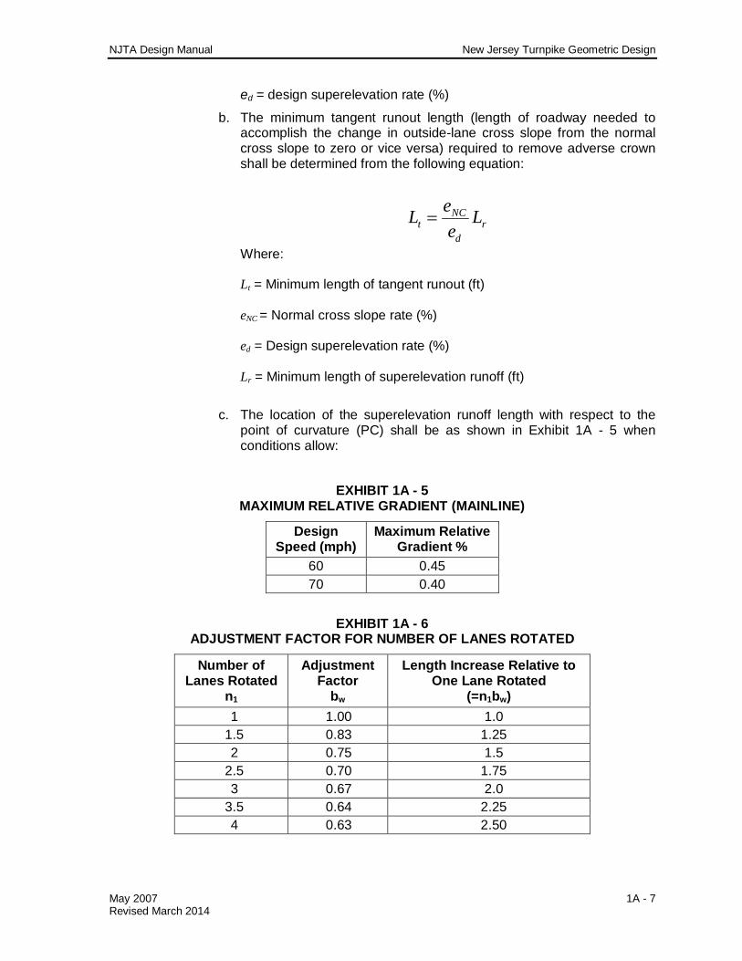
b. The minimum tangent runout length (length of roadway needed to accomplish the change in outside-lane cross slope from the normal cross slope to zero or vice versa) required to remove adverse crown shall be determined from the following equation:
rd
NCt L
eeL
Where: Lt = Minimum length of tangent runout (ft) eNC = Normal cross slope rate (%) ed = Design superelevation rate (%) Lr = Minimum length of superelevation runoff (ft)
c. The location of the superelevation runoff length with respect to the point of curvature (PC) shall be as shown in Exhibit 1A - 5 when conditions allow:
EXHIBIT 1A - 5
MAXIMUM RELATIVE GRADIENT (MAINLINE)
Design Speed (mph)
Maximum Relative Gradient %
60 0.45 70 0.40
EXHIBIT 1A - 6 ADJUSTMENT FACTOR FOR NUMBER OF LANES ROTATED
Number of Lanes Rotated
n1
Adjustment Factor
bw
Length Increase Relative to One Lane Rotated
(=n1bw) 1 1.00 1.0
1.5 0.83 1.25 2 0.75 1.5
2.5 0.70 1.75 3 0.67 2.0
3.5 0.64 2.25 4 0.63 2.50
NJTA Design Manual New Jersey Turnpike Geometric Design
May 2007 1A - 8 Revised March 2014
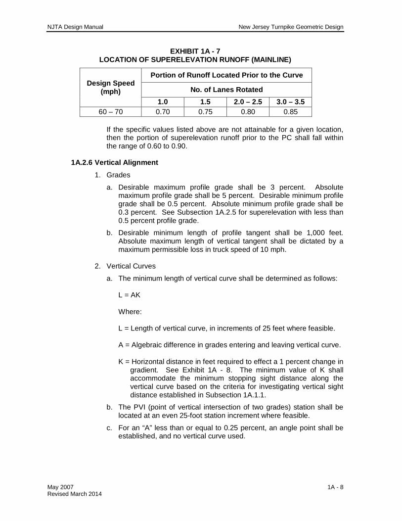
EXHIBIT 1A - 7 LOCATION OF SUPERELEVATION RUNOFF (MAINLINE)
Design Speed (mph)
Portion of Runoff Located Prior to the Curve
No. of Lanes Rotated 1.0 1.5 2.0 – 2.5 3.0 – 3.5
60 – 70 0.70 0.75 0.80 0.85 If the specific values listed above are not attainable for a given location, then the portion of superelevation runoff prior to the PC shall fall within the range of 0.60 to 0.90.
1A.2.6 Vertical Alignment
1. Grades
a. Desirable maximum profile grade shall be 3 percent. Absolute maximum profile grade shall be 5 percent. Desirable minimum profile grade shall be 0.5 percent. Absolute minimum profile grade shall be 0.3 percent. See Subsection 1A.2.5 for superelevation with less than 0.5 percent profile grade.
b. Desirable minimum length of profile tangent shall be 1,000 feet. Absolute maximum length of vertical tangent shall be dictated by a maximum permissible loss in truck speed of 10 mph.
2. Vertical Curves
a. The minimum length of vertical curve shall be determined as follows: L = AK Where: L = Length of vertical curve, in increments of 25 feet where feasible. A = Algebraic difference in grades entering and leaving vertical curve. K = Horizontal distance in feet required to effect a 1 percent change in
gradient. See Exhibit 1A - 8. The minimum value of K shall accommodate the minimum stopping sight distance along the vertical curve based on the criteria for investigating vertical sight distance established in Subsection 1A.1.1.
b. The PVI (point of vertical intersection of two grades) station shall be located at an even 25-foot station increment where feasible.
c. For an “A” less than or equal to 0.25 percent, an angle point shall be established, and no vertical curve used.

NJTA Design Manual New Jersey Turnpike Geometric Design
May 2007 1A - 9 Revised March 2014
EXHIBIT 1A - 8 DESIGN CONTROLS FOR MAINLINE ROADWAY VERTICAL CURVES
Design Speed (mph)
Stopping Sight Distance (ft) Crest K Sag K Minimum
60 570 245 136 70 730 400 181
1A.2.7 Pavement
The mainline pavement section shall be constructed as shown on Exhibit 1A - 9. Current pavement mix types to be used for each of the courses shown in the pavement sections shall be as directed by the Authority. 1. Embankment, Grade A, shall be a minimum of 18 inches deep under
travel lanes. In locations where existing pavement is widened, Grade A material is to be deeper, if necessary, to match template grade of existing pavement. Template grade (top of subgrade below Grade A embankment) shall slope transversely a minimum of 2% or match cross slope of roadway. Template grade shall be constructed transversely under the full section, without breaks in cross slope, on each individual roadway and in such a manner as to provide positive drainage (daylight section or underdrains).
2. In areas where existing and currently designed resurfacing depth
approaches 12 inches, or more, at the existing pavement / shoulder interface, investigations shall be made as to the feasibility of leaving the existing shoulder in place as a portion of the proposed pavement section.
3. At interfaces between Turnpike pavement and the pavement of outside agencies, the higher-class pavement shall be constructed first, with offset and steps per course as shown. Account for offset and stepping quantity computations.
4. The various pavement interface and stepping details shown on Exhibit 1A
- 10 through Exhibit 1A - 14 are for Turnpike pavement. Adjust steps accordingly to match other pavement sections. Account for stepping quantity computations. With curb, courses terminate at curb face as shown, any stepping shall be from back of curb.
5. In the pavement interface details shown on Exhibit 1A - 13, the existing
pavement is from the 1985-90 widening construction. Each area shall be reviewed and adjusted to conform with existing construction. Where proposed widening includes resurfacing the adjacent existing pavement, omit the 6-inch removal of the top course and place the new surface course pavement joint at least 2 feet from the existing edge of pavement.
6. When computing quantities for asphaltic concrete items, the following
conversion factors are to be used for preliminary estimates and are to be verified for each project prior to completion of the final quantities.

NJTA Design Manual New Jersey Turnpike Geometric Design
May 2007 1A - 10 Revised March 2014
Surface Course 156.0 ± lb/cuft. Intermediate Course 157.5 ± lb/cuft. Base Course 159.0 ± lb/cuft.
7. Tack coat shall be applied to all existing (milled) pavement surfaces just
prior to asphalt resurfacing. Tack coat shall also be applied to all exposed cut surfaces of an existing asphalt pavement section which is stepped to interface with a proposed pavement section. Tack coat will not be required between subsequent asphalt layers of proposed pavement unless:
a. The underlying layer has been contaminated.
b. The underlying layer has been exposed to prolonged traffic use.
c. It is otherwise required on the drawings or in special provisions.
8. Hot mixed asphalt pavements shall be constructed in accordance with the Standard Specifications, as amended by the Supplemental Specifications. Surface and intermediate courses for Turnpike Pavement shall each be placed in a single lift. The base course for Turnpike Pavement shall be placed in two lifts. Pavement course lifts shall conform to the following:
a. The minimum lift thickness shall be three times the nominal maximum aggregate size of the specified pavement mix type.
b. The maximum lift thickness shall be five times the nominal maximum aggregate size of the specified pavement mix type.
The above lift requirements shall apply to U-Turn and Car Parking pavement sections, as well as any variations of Turnpike Pavement used in resurfacing / re-grading projects.
EXHIBIT 1A - 9 TURNPIKE PAVEMENT (MAINLINE, RAMP & SHOULDERS)

NJTA Design Manual New Jersey Turnpike Geometric Design
May 2007 1A - 11 Revised March 2014
EXHIBIT 1A - 10 PAVEMENT REMOVAL AND RECONSTRUCTION DETAIL
EXHIBIT 1A - 11 LONGITUDINAL PAVEMENT STEPPING DETAIL

NJTA Design Manual New Jersey Turnpike Geometric Design
May 2007 1A - 12 Revised March 2014
EXHIBIT 1A - 12 TRANSVERSE PAVEMENT STEPPING DETAIL

NJTA Design Manual New Jersey Turnpike Geometric Design
May 2007 1A - 13 Revised March 2014
EXHIBIT 1A - 13 NEW PAVEMENT INTERFACE WITH EXISTING PAVEMENT
EXHIBIT 1A - 14 TOLL PLAZA PAVEMENT INTERFACE

NJTA Design Manual New Jersey Turnpike Geometric Design
May 2007 1A - 14 Revised March 2014
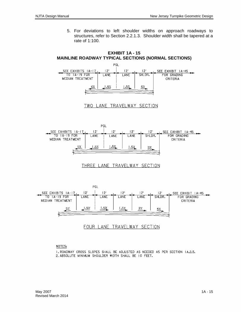
1A.2.8 Typical Section 1. For typical mainline roadway dimensions and cross slopes for normal
and superelevated sections, see Exhibit 1A - 15 and Exhibit 1A - 16. 2. Rumble Strips
Rumble strips shall be constructed on all mainline roadway outside shoulders and on all median shoulders that are 5 feet or greater in width. Placement of rumble strips along mainline roadways shall be limited as follows:
a. On approach to mainline toll plazas, the rumble strips shall terminate at the end of the mainline normal section.
b. At entrance ramp terminals, rumble strips on outside shoulders shall terminate at the point of the physical gore and resume at the end of the acceleration lane taper.
c. At exit ramp terminals, rumble strips on outside shoulders shall terminate at the start of the deceleration lane taper and resume at the point of the physical gore.
d. On approach to bridges, the rumble strips shall terminate at the abutment joint.
e. For rumble strip limitations at U-Turns and Z-Turns, refer to Section 1A.5.3 and Section 1A.5.4, respectively.
f. Rumble strips may be eliminated at other locations at the direction of the Authority’s Engineering Department.
3. Median Treatment
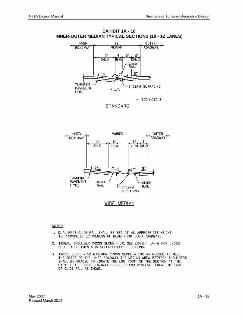
a. The median type to be used shall be dictated by the overall design considerations of a specific situation. The various median types are shown on Exhibit 1A - 17 to Exhibit 1A - 19. Medians other than the standards shown shall require approval from the Authority’s Engineering Department.
b. The standard centerline median width (edge of travel way to edge of travel way) shall be 26 feet. The absolute minimum width shall be 13 feet or 7 feet, depending on the specific situation, to match the existing roadway section design.
c. The standard inner-outer median width (edge of travel way to edge of travel way) shall be 26 feet. Where the outer roadway is 4 lanes, the standard width shall be 33 feet between same direction roadways. The absolute minimum width shall be 20 feet or 15 feet, depending on the specific situation, to match the existing roadway section design.
4. Lateral Bridge Clearances
For mainline roadways, clearances shall be provided as shown on Exhibit 1A - 20.
NJTA Design Manual New Jersey Turnpike Geometric Design
May 2007 1A - 15 Revised March 2014
5. For deviations to left shoulder widths on approach roadways to structures, refer to Section 2.2.1.3. Shoulder width shall be tapered at a rate of 1:100.
EXHIBIT 1A - 15 MAINLINE ROADWAY TYPICAL SECTIONS (NORMAL SECTIONS)
NJTA Design Manual New Jersey Turnpike Geometric Design
May 2007 1A - 16 Revised March 2014
EXHIBIT 1A - 16 MAINLINE ROADWAY TYPICAL SECTIONS (SUPERELEVATED SECTIONS)

NJTA Design Manual New Jersey Turnpike Geometric Design
May 2007 1A - 17 Revised March 2014
EXHIBIT 1A - 17 CENTER MEDIAN TYPICAL SECTIONS
NJTA Design Manual New Jersey Turnpike Geometric Design
May 2007 1A - 18 Revised March 2014
EXHIBIT 1A - 18 INNER-OUTER MEDIAN TYPICAL SECTIONS (10 - 12 LANES)

NJTA Design Manual New Jersey Turnpike Geometric Design
May 2007 1A - 19 Revised March 2014
EXHIBIT 1A - 19 INNER-OUTER MEDIAN TYPICAL SECTIONS (14 LANES)

NJTA Design Manual New Jersey Turnpike Geometric Design
May 2007 1A - 20 Revised March 2014
EXHIBIT 1A - 20 LATERAL BRIDGE CLEARANCES - MAINLINE
1A.2.9 Detours 1. The minimum design speed shall be 5 mph over regulatory speed limit
with no reduction in the posted speed limit. Absolute minimum reduction in design speed shall be 10 mph.
2. Horizontal Alignment
a. Desirable minimum radius curve shall be 3,000 feet. Absolute minimum radius curve shall be 1,800 feet. When back to back reverse curves are necessary, a sufficient tangent distance to effect the superelevation transitions is to be provided.
b. Superelevation rates and transition lengths are to be consistent with the horizontal alignment and shall be reviewed on a case by case basis with the objective of attaining the smoothest ride possible.

NJTA Design Manual New Jersey Turnpike Geometric Design
May 2007 1A - 21 Revised March 2014
3. Vertical Alignment Maximum profile grade shall be 3 percent. Minimum profile grade shall be sufficient to keep pavement free of ponding water.
4. Detour pavement shall be the same as mainline pavement. Any use of a
substandard pavement section for a short period of time is subject to Authority’s Engineering Department approval.
5. Typical detour section shall consist of normal 12-foot lanes and normal
left and right shoulders throughout. Variations to this shall be treated with standard maintenance and protection of traffic practices.
6. Clearances shall be the same as for mainline roadways and interchange
ramps. Refer to Subsection 1A.1.1. 7. Refer to Section 9 of this manual for detour signing. 8. All detours must be striped as if they were a permanent roadway. Where
necessary, temporary pavement stripes may be used. 9. Temporary construction measures necessary for the protection of the
environment (e.g. area of construction detours or temporary stream crossings) shall be adequately shown on plans and permits, and the payment therefore covered in the plans and specifications.
1A.3 INTERCHANGE RAMPS 1A.3.1 Roadway Designation
Ramps shall be designated such that the origin and then the destination of that roadway are given in order (i.e. from the toll plaza to the north – TN Ramp or from the north inner roadway to the toll plaza – NIT). See Subsection 1.4.1 of the Procedures Manual for a complete listing.
1A.3.2 Design Speed The design speed for interchange ramps shall vary from 25 mph minimum to 50 mph maximum, with 40 mph desirable minimum for intermediate portions of long ramps. The central radius of the ramp shall be used for design speed control. Refer to Exhibit 1A - 21.

NJTA Design Manual New Jersey Turnpike Geometric Design
May 2007 1A - 22 Revised March 2014
EXHIBIT 1A - 21 MINIMUM CURVE RADII FOR RAMP DESIGN SPEED
Ramp Central Radius in Feet for Maximum Superelevation
(Emax=6%)
Recommended Design Speed
(mph) 150 25 235 30 340 35 485 40 650 45 840 50
1A.3.3 Stopping Sight Distance
The minimum stopping sight distance for the various interchange ramp design speeds shall be as shown in Exhibit 1A - 22.
EXHIBIT 1A - 22
MINIMUM STOPPING SIGHT DISTANCE FOR INTERCHANGE RAMPS
Design Speed (mph)
Minimum Stopping Sight Distance (ft)
25 155 30 200 35 250 40 305 45 360 50 425
1A.3.4 Horizontal Alignment
1. Radii The desirable minimum radius shall be 235 feet. The absolute minimum radius shall be 150 feet (waiver required from Chief Engineer). It is desirable to use as large a radius as project conditions will allow.
2. Ramp configuration and transition curves shall be as indicated on Exhibit
1A - 23. 3. The minimum lengths of curves shall be as indicated on Exhibit 1A - 23. 4. The minimum length of tangent between reverse curves shall be sufficient
to accommodate the superelevation transitions between the reversing curves.

NJTA Design Manual New Jersey Turnpike Geometric Design
May 2007 1A - 23 Revised March 2014
EXHIBIT 1A - 23 INTERCHANGE RAMP GEOMETRY
NJTA Design Manual New Jersey Turnpike Geometric Design
May 2007 1A - 24 Revised March 2014
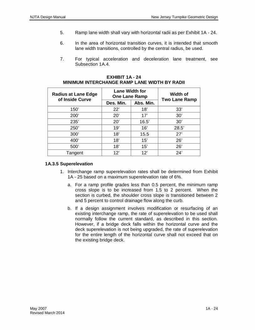
5. Ramp lane width shall vary with horizontal radii as per Exhibit 1A - 24. 6. In the area of horizontal transition curves, it is intended that smooth
lane width transitions, controlled by the central radius, be used. 7. For typical acceleration and deceleration lane treatment, see
Subsection 1A.4.
EXHIBIT 1A - 24 MINIMUM INTERCHANGE RAMP LANE WIDTH BY RADII
Radius at Lane Edge of Inside Curve
Lane Width for One Lane Ramp Width of
Two Lane Ramp Des. Min. Abs. Min.
150’ 22’ 18’ 33’ 200’ 20’ 17’ 30’ 235’ 20’ 16.5’ 30’ 250’ 19’ 16’ 28.5’ 300’ 18’ 15.5 27’ 400’ 18’ 15’ 26’ 500’ 18’ 15’ 26’
Tangent 12’ 12’ 24’
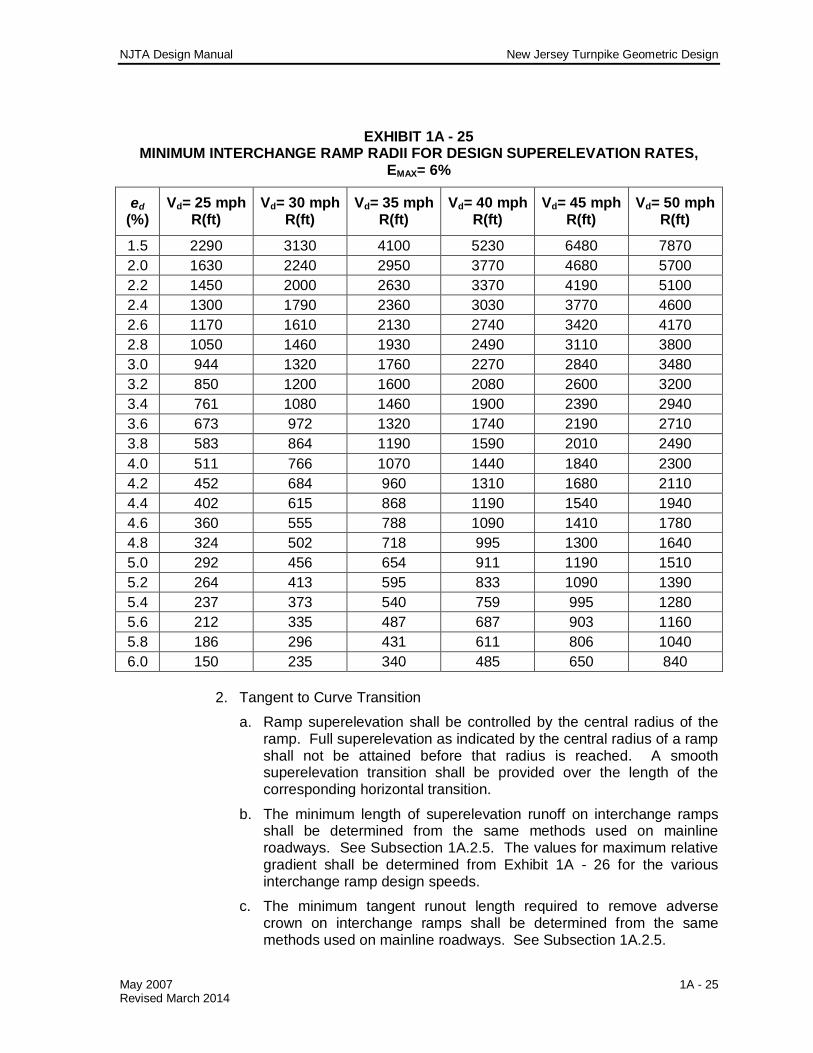
1A.3.5 Superelevation 1. Interchange ramp superelevation rates shall be determined from Exhibit
1A - 25 based on a maximum superelevation rate of 6%.
a. For a ramp profile grades less than 0.5 percent, the minimum ramp cross slope is to be increased from 1.5 to 2 percent. When the section is curbed, the shoulder cross slope is transitioned between 2 and 5 percent to control drainage flow along the curb.
b. If a design assignment involves modification or resurfacing of an existing interchange ramp, the rate of superelevation to be used shall normally follow the current standard, as described in this section. However, if a bridge deck falls within the horizontal curve and the deck superelevation is not being upgraded, the rate of superelevation for the entire length of the horizontal curve shall not exceed that on the existing bridge deck.
NJTA Design Manual New Jersey Turnpike Geometric Design
May 2007 1A - 25 Revised March 2014
EXHIBIT 1A - 25 MINIMUM INTERCHANGE RAMP RADII FOR DESIGN SUPERELEVATION RATES,
EMAX= 6%
ed (%)
Vd= 25 mph R(ft)
Vd= 30 mph R(ft)
Vd= 35 mph R(ft)
Vd= 40 mph R(ft)
Vd= 45 mph R(ft)
Vd= 50 mph R(ft)
1.5 2290 3130 4100 5230 6480 7870 2.0 1630 2240 2950 3770 4680 5700 2.2 1450 2000 2630 3370 4190 5100 2.4 1300 1790 2360 3030 3770 4600 2.6 1170 1610 2130 2740 3420 4170 2.8 1050 1460 1930 2490 3110 3800 3.0 944 1320 1760 2270 2840 3480 3.2 850 1200 1600 2080 2600 3200 3.4 761 1080 1460 1900 2390 2940 3.6 673 972 1320 1740 2190 2710 3.8 583 864 1190 1590 2010 2490 4.0 511 766 1070 1440 1840 2300 4.2 452 684 960 1310 1680 2110 4.4 402 615 868 1190 1540 1940 4.6 360 555 788 1090 1410 1780 4.8 324 502 718 995 1300 1640 5.0 292 456 654 911 1190 1510 5.2 264 413 595 833 1090 1390 5.4 237 373 540 759 995 1280 5.6 212 335 487 687 903 1160 5.8 186 296 431 611 806 1040 6.0 150 235 340 485 650 840
2. Tangent to Curve Transition
a. Ramp superelevation shall be controlled by the central radius of the ramp. Full superelevation as indicated by the central radius of a ramp shall not be attained before that radius is reached. A smooth superelevation transition shall be provided over the length of the corresponding horizontal transition.
b. The minimum length of superelevation runoff on interchange ramps shall be determined from the same methods used on mainline roadways. See Subsection 1A.2.5. The values for maximum relative gradient shall be determined from Exhibit 1A - 26 for the various interchange ramp design speeds.
c. The minimum tangent runout length required to remove adverse crown on interchange ramps shall be determined from the same methods used on mainline roadways. See Subsection 1A.2.5.
NJTA Design Manual New Jersey Turnpike Geometric Design
May 2007 1A - 26 Revised March 2014
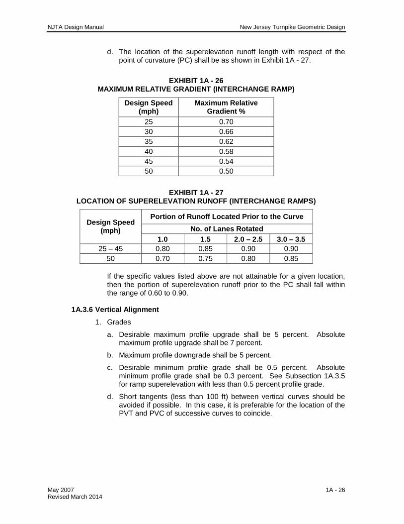
d. The location of the superelevation runoff length with respect of the point of curvature (PC) shall be as shown in Exhibit 1A - 27.
EXHIBIT 1A - 26 MAXIMUM RELATIVE GRADIENT (INTERCHANGE RAMP)
Design Speed (mph)
Maximum Relative Gradient %
25 0.70 30 0.66 35 0.62 40 0.58 45 0.54 50 0.50
EXHIBIT 1A - 27 LOCATION OF SUPERELEVATION RUNOFF (INTERCHANGE RAMPS)
Design Speed (mph)
Portion of Runoff Located Prior to the Curve No. of Lanes Rotated
1.0 1.5 2.0 – 2.5 3.0 – 3.5 25 – 45 0.80 0.85 0.90 0.90
50 0.70 0.75 0.80 0.85 If the specific values listed above are not attainable for a given location, then the portion of superelevation runoff prior to the PC shall fall within the range of 0.60 to 0.90.
1A.3.6 Vertical Alignment
1. Grades
a. Desirable maximum profile upgrade shall be 5 percent. Absolute maximum profile upgrade shall be 7 percent.
b. Maximum profile downgrade shall be 5 percent.
c. Desirable minimum profile grade shall be 0.5 percent. Absolute minimum profile grade shall be 0.3 percent. See Subsection 1A.3.5 for ramp superelevation with less than 0.5 percent profile grade.
d. Short tangents (less than 100 ft) between vertical curves should be avoided if possible. In this case, it is preferable for the location of the PVT and PVC of successive curves to coincide.

NJTA Design Manual New Jersey Turnpike Geometric Design
May 2007 1A - 27 Revised March 2014
2. Vertical Curves
a. The minimum length of vertical curve shall be determined from the same methods used on mainline roadways. See Subsection 1A.2.6. The minimum value of K shall be determined from Exhibit 1A - 28 for the various interchange ramp design speeds.
b. The PVI (point of vertical intersection of two grades) station shall be located at an even 25-foot station increment where feasible.
c. For an “A” less than or equal to 0.25 percent, an angle point shall be established, and no vertical curve used.
EXHIBIT 1A - 28 DESIGN CONTROLS FOR INTERCHANGE RAMP VERTICAL CURVES
Design Speed (mph)
Stopping Sight Distance (ft) Crest K Sag K
Minimum 25 155 20 30 30 200 30 40 35 250 47 50 40 305 70 64 45 360 98 79 50 425 136 96
1A.3.7 Pavement
The interchange ramp pavement section shall be similar to the mainline section. See Subsection 1A.2.7.
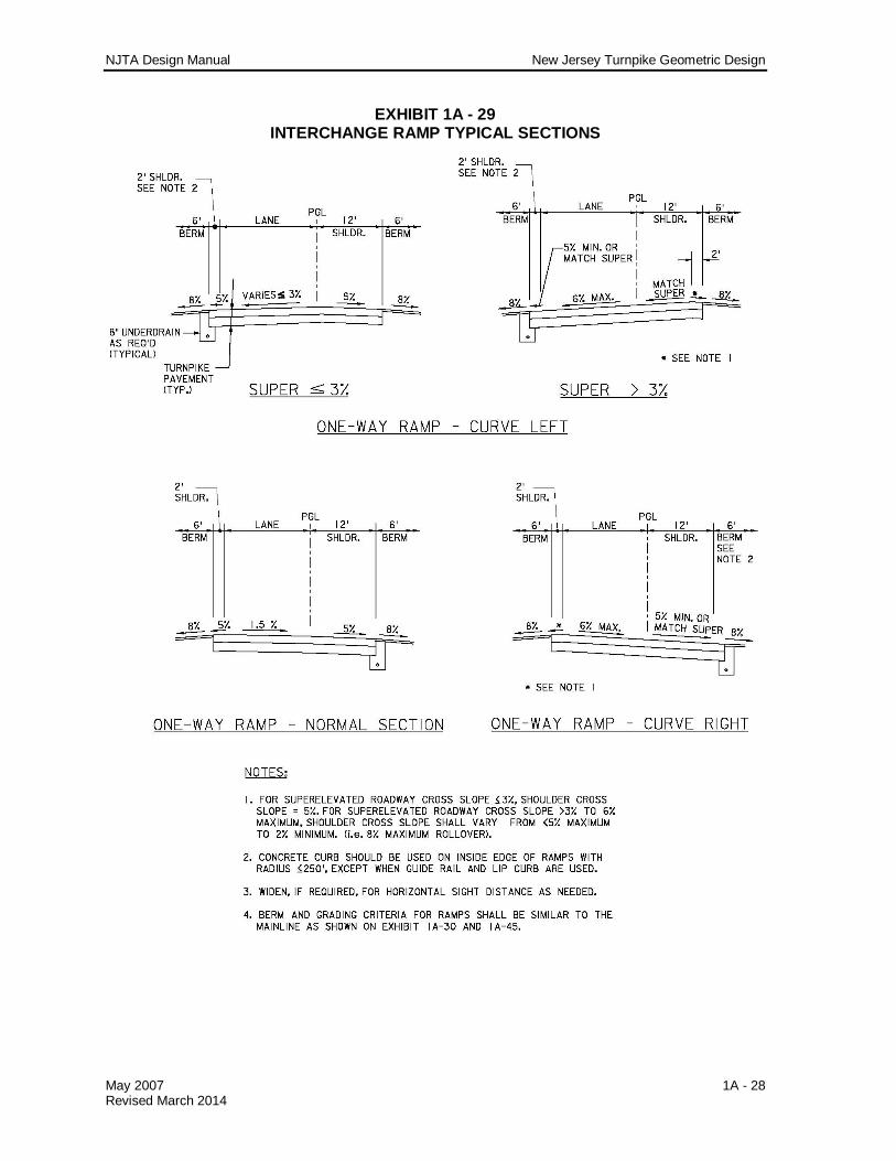
1A.3.8 Typical Section 1. For typical interchange ramp dimensions and cross slopes for normal and
superelevated sections, see Exhibit 1A - 29. 2. Rumble Strips shall not be constructed on interchange ramps. Refer to
Section 1A.2.8 for the limits of rumble strip construction at interchange areas.
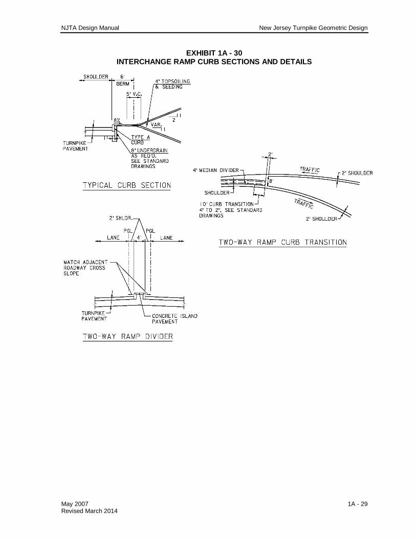
3. Median treatment between ramps is shown on Exhibit 1A - 30. 4. For placement of asphalt lip curb with guide rail, see Section 3.2.6.11. 5. Concrete curb shall be used on the inside edge of shoulder on ramps with
a radius of 250 feet or less, except when guide rail and lip curb are used.
6. Lateral Bridge Clearances For ramps, clearances shall be provided as shown on Exhibit 1A - 31.
NJTA Design Manual New Jersey Turnpike Geometric Design
May 2007 1A - 28 Revised March 2014
EXHIBIT 1A - 29 INTERCHANGE RAMP TYPICAL SECTIONS
NJTA Design Manual New Jersey Turnpike Geometric Design
May 2007 1A - 29 Revised March 2014
EXHIBIT 1A - 30 INTERCHANGE RAMP CURB SECTIONS AND DETAILS

NJTA Design Manual New Jersey Turnpike Geometric Design
May 2007 1A - 30 Revised March 2014
EXHIBIT 1A - 31 LATERAL BRIDGE CLEARANCES - RAMPS
1A.3.9 Detours
1. The design speed shall be 25 mph minimum. 2. Horizontal Alignment
a. Minimum radius curve shall be 150 feet.
b. Superelevation rates and transition lengths are to be consistent with the horizontal alignment and shall be reviewed on a case-by-case basis with objective of attaining the smoothest ride possible.

NJTA Design Manual New Jersey Turnpike Geometric Design
May 2007 1A - 31 Revised March 2014
3. Vertical Alignment Maximum profile grade shall be 7 percent. Minimum profile grade shall be sufficient to keep pavement free of ponding water.
4. Detour pavement shall be the same as mainline pavement. Any use of a
substandard pavement section for a short period of time is subject to Authority’s Engineering Department approval.
5. Typical detour section shall be similar to the normal ramp section.
Variations to this shall be treated with standard maintenance and protection of traffic procedures.
6. Clearances shall be the same as for mainline roadways and interchange
ramps. Refer to Subsection 1A.1.1. 7. Refer to Section 9 of this manual for detour signing on ramps. 8. All detours must be striped as if they were a permanent ramp. Where
necessary, temporary pavement stripes may be used. 9. All ramp detours shall be lighted; see Section 7 of this manual. 10. Temporary construction measures necessary for the protection of the
environment (e.g. area of construction detours or temporary stream crossings) shall be adequately shown on plans and permit applications, and the payment therefore covered in the plans and specifications.
1A.4 AUXILIARY LANES 1A.4.1 Acceleration Lanes
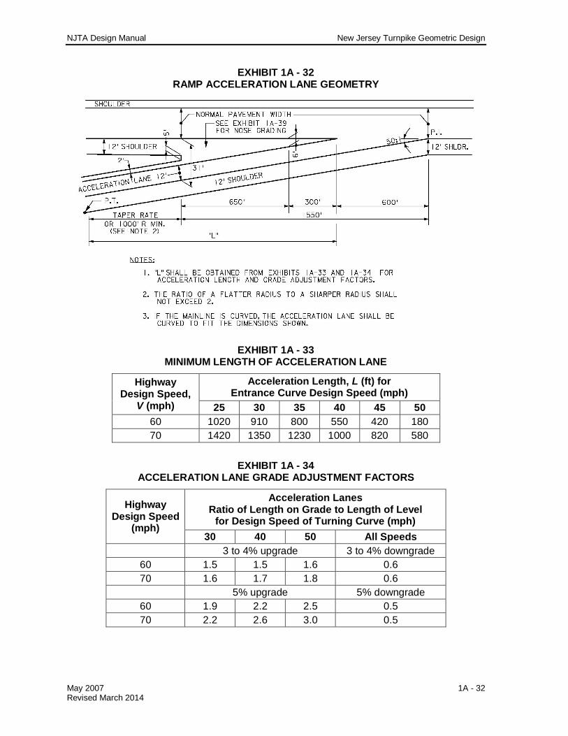
A typical acceleration lane is shown in Exhibit 1A - 32. 1. Where the acceleration lane falls within a section of roadway with 3
percent or greater profile (upgrade or downgrade), the acceleration lengths from Exhibit 1A - 33 shall be adjusted by the ratios indicated in Exhibit 1A - 34 to determine minimum acceleration lane lengths.
2. It is intended that a two-lane entrance ramp shall consist of the typical
ramp acceleration geometry as shown in Exhibit 1A - 32, followed by consecutive single lane drops totaling 2,400 feet to merge the ramp lanes into the mainline roadway. The continuity of the through (mainline) roadway shall be maintained at all times. A typical two-lane entrance ramp is shown in Exhibit 1A - 35. This application can be further extended to the merge of two major roadways, requiring a total minimum length of 3,600 feet for three consecutive lane drops with the roadway lanes on the left having mainline priority. In both instances, the minimum length shall be adjusted by the ratios in Exhibit 1A - 34 where the profile (upgrade or downgrade) is 3 percent or greater.
NJTA Design Manual New Jersey Turnpike Geometric Design
May 2007 1A - 32 Revised March 2014
EXHIBIT 1A - 32 RAMP ACCELERATION LANE GEOMETRY
EXHIBIT 1A - 33 MINIMUM LENGTH OF ACCELERATION LANE
Highway Design Speed,
V (mph)
Acceleration Length, L (ft) for Entrance Curve Design Speed (mph)
25 30 35 40 45 50 60 1020 910 800 550 420 180 70 1420 1350 1230 1000 820 580
EXHIBIT 1A - 34
ACCELERATION LANE GRADE ADJUSTMENT FACTORS
Highway Design Speed
(mph)
Acceleration Lanes Ratio of Length on Grade to Length of Level
for Design Speed of Turning Curve (mph) 30 40 50 All Speeds
3 to 4% upgrade 3 to 4% downgrade 60 1.5 1.5 1.6 0.6 70 1.6 1.7 1.8 0.6
5% upgrade 5% downgrade 60 1.9 2.2 2.5 0.5 70 2.2 2.6 3.0 0.5

NJTA Design Manual New Jersey Turnpike Geometric Design
May 2007 1A - 33 Revised March 2014
EXHIBIT 1A - 35 TWO-LANE ENTRANCE RAMP
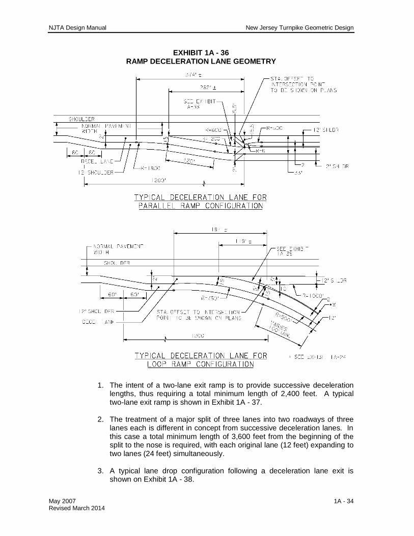
1A.4.2 Deceleration Lanes Two types of deceleration lanes are shown on Exhibit 1A - 36. The application of these two types is dependent upon the overall geometry of the situation. The “Parallel Ramp Configuration” is generally used in conjunction with a dual-dual roadway.
NJTA Design Manual New Jersey Turnpike Geometric Design
May 2007 1A - 34 Revised March 2014
EXHIBIT 1A - 36 RAMP DECELERATION LANE GEOMETRY
1. The intent of a two-lane exit ramp is to provide successive deceleration
lengths, thus requiring a total minimum length of 2,400 feet. A typical two-lane exit ramp is shown in Exhibit 1A - 37.
2. The treatment of a major split of three lanes into two roadways of three
lanes each is different in concept from successive deceleration lanes. In this case a total minimum length of 3,600 feet from the beginning of the split to the nose is required, with each original lane (12 feet) expanding to two lanes (24 feet) simultaneously.
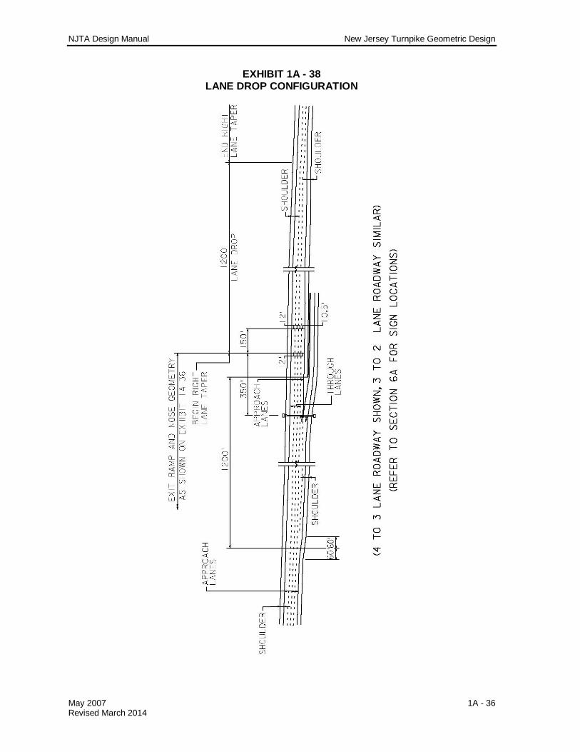
3. A typical lane drop configuration following a deceleration lane exit is
shown on Exhibit 1A - 38.

NJTA Design Manual New Jersey Turnpike Geometric Design
May 2007 1A - 35 Revised March 2014
EXHIBIT 1A - 37 TWO-LANE EXIT RAMP
NJTA Design Manual New Jersey Turnpike Geometric Design
May 2007 1A - 36 Revised March 2014
EXHIBIT 1A - 38 LANE DROP CONFIGURATION

NJTA Design Manual New Jersey Turnpike Geometric Design
May 2007 1A - 37 Revised March 2014
4. Typical nose grading between mainline roadway and auxiliary lanes is shown in Exhibit 1A - 39.
EXHIBIT 1A - 39 TYPICAL NOSE GRADING
1A.4.3 Climbing Lanes With a maximum of 3 percent grades, the Authority does not use truck climbing lanes. As indicated in Subsection 1A.2.6, the absolute minimum length of vertical tangent shall be limited by a maximum permissible loss in truck speed of 10 mph.
1A.5 OTHER ROADWAYS 1A.5.1 Crossroads
Where local roads are being replaced, the intent of the Authority with respect to any work under the jurisdiction of the state, county, municipality, or any other agency is “replacement in kind”, according to the present standards of that agency. All such work is subject to the approval of the Authority’s Engineering Department and must be previously agreed to in writing by the concerned agency, as noted elsewhere in this manual and the Procedures Manual. Similarly, all detouring and/or closing of local roads during construction must be approved by the appropriate agencies in accordance with the Procedures Manual.
1A.5.2 Access and Service Roads 1. Treatment shall be similar to Subsection 1A.5.1. 2. For parking lots and driveways at toll plaza buildings and other locations
within the Turnpike right of way, the pavement section shall be as shown on Exhibit 1A - 40. Refer to Subsection 1A.2.7 for additional information and details.

NJTA Design Manual New Jersey Turnpike Geometric Design
May 2007 1A - 38 Revised March 2014
EXHIBIT 1A - 40 CAR PARKING PAVEMENT SECTION
1A.5.3 U-Turns 1. U-Turns shall be designated by milepost location. Refer to Section 6A for
U-Turn signing. 2. Location
a. Within one mile of and on each side of an interchange.
b. No more than five miles apart between interchanges.
3. Configuration and Alignment
a. All U-Turns shall be grade separated through the end span of a structure when the mainline passes over a crossroad etc., or on a separate overhead structure when necessary.
b. Maximum profile grade shall be 5 percent.
c. Rumble strips shall not be placed in the mainline shoulder within 300 feet on either side of the U-Turn entrance / exit.
d. For all other information, see Exhibit 1A - 41 and Exhibit 1A - 43.
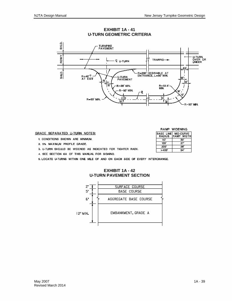
4. The pavement section for grade separated U-Turns shall be as shown on Exhibit 1A - 42. Refer to Section 1A.2.7 for additional information and details.
NJTA Design Manual New Jersey Turnpike Geometric Design
May 2007 1A - 39 Revised March 2014
EXHIBIT 1A - 41 U-TURN GEOMETRIC CRITERIA
EXHIBIT 1A - 42 U-TURN PAVEMENT SECTION

NJTA Design Manual New Jersey Turnpike Geometric Design
May 2007 1A - 40 Revised March 2014
EXHIBIT 1A - 43 U-TURN TYPICAL SECTIONS
NJTA Design Manual New Jersey Turnpike Geometric Design
May 2007 1A - 41 Revised March 2014
1A.5.4 Z-Turns 1. Z-Turns shall be designated by milepost location. 2. Use and Location
a. Z-Turns shall be used on dual-dual roadway between same direction roadways as a connection between those roadways.
b. Z-Turns shall be used in conjunction with grade separated U-turns and shall be approximately 2,500 feet on each side of the U-Turns for 70 mph design speed and approximately 2,000 feet for 60 mph design speeds. The absolute minimum distance shall be 1,500 feet.
c. Drainage within Z-Turn median shall be maintained.
d. Refer to Section 6A for signing.
3. Configuration
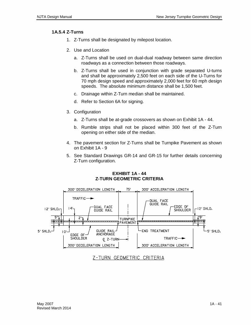
a. Z-Turns shall be at-grade crossovers as shown on Exhibit 1A - 44.
b. Rumble strips shall not be placed within 300 feet of the Z-Turn opening on either side of the median.
4. The pavement section for Z-Turns shall be Turnpike Pavement as shown
on Exhibit 1A - 9
5. See Standard Drawings GR-14 and GR-15 for further details concerning Z-Turn configuration.
EXHIBIT 1A - 44 Z-TURN GEOMETRIC CRITERIA

NJTA Design Manual New Jersey Turnpike Geometric Design
May 2007 1A - 42 Revised March 2014
1A.6 GRADING CRITERIA The general grading criteria set forth in this section are intended to be used as guidelines to achieve an economically feasible, safe and aesthetically pleasing design. Variations to the specified criteria are permissible as long as the design adequately complies with the intent of the guidelines. Variations in side slopes should be investigated in order to obtain a favorable earthwork balance. Every effort is to be made to limit the use of critical slopes where feasible so as to eliminate the need for guide rail. Consideration shall be given to the impact on right of way, earthwork, aesthetics, existing trees, utilities, regulated areas, etc.
1. Grading in Fill Areas
a. Variable side slopes, depending on the height of fill at the PVI of berm, shall be used for all ramps and for existing Turnpike roadways. See Exhibit 1A - 45.
i. 0 - 5 feet fills - 6:1 slope ii. 5-10 feet fills - 4:1 slope iii. 10 feet and greater fills - 2:1 slope maximum
b. Refer to Section 3 (Guide Rail / Median Barrier / Attenuator Design) of this Manual for guide rail requirements related to height of fill. Safety grading criteria may be utilized on mainline roadways as directed by the Authority’s Engineering Department in order to eliminate guide rail warrants.
c. Mainline and ramp sections shall have a berm width of 6 feet minimum sloping away from the roadway at an 8 percent grade.
d. All roundings shall have 5-foot vertical curves.
2. Grading in Cut Areas
a. 2:1 maximum side slopes are recommended throughout. See Exhibit 1A - 45.
b. Berm widths are the same as for fill sections.
c. All roundings shall have 5-foot vertical curves.
d. Cut sections in rock will be subject to Authority’s Engineering Department approval of the Engineer’s soils recommendations.
e. In borrow projects, the Engineer shall investigate the possibility of using flatter cut slopes in an attempt to achieve a more favorable earthwork balance.

NJTA Design Manual New Jersey Turnpike Geometric Design
May 2007 1A - 43 Revised March 2014
EXHIBIT 1A - 45 TURNPIKE GRADING CRITERIA
NJTA Design Manual New Jersey Turnpike Geometric Design
May 2007 1A - 44 Revised March 2014
1A.7 FENCING 1. General
The policy of the Authority is to fence all Turnpike right of way.
2. Usage
a. Chain Link fence shall be used around interchanges, service areas and maintenance areas; along the right of way adjacent to existing commercial or residential areas or areas zoned for future commercial or residential development and 1,000 feet either side of the limits of these areas; along local roads and 500 feet either side of local roads along the Authority’s right of way; and at all other locations at the direction of the Authority’s Engineering Department.
b. Chain link fence shall be as per the Standard Drawings.
3. Configuration
a. Placement of fence with respect to the right of way line shall be as per the Standard Drawings.
b. Fence intersecting waterways which have a bottom width of 6 feet or greater will be turned and run parallel to the stream, along the top of bank, to the culvert headwall through the roadway embankment. Fencing will then be carried up behind the wingwall, across behind the headblock and back out to the right of way along the far side of the waterway. The median area crossed by the waterway will not be fenced. On one selected side of that portion of the fence running perpendicular between the ROW and roadway embankment, the engineer shall consider placing a single vehicular gate.
c. Vehicular gate dimensions shall be as shown on the Standard Drawings. These gates shall be placed on that side of each water course which affords best access for maintenance. Consideration is to be given to proximity of local road access, the extent of trees, vegetation and ground contour to determine if a gate is required and if so where it is to be placed.
d. A right of way fence is to be carried across streams and ditches having less than a 6-foot bottom width. Line posts are to be spaced so that no post is erected in the bed or slopes of the ditch. The bottom of the fence shall provide for one foot freeboard above the ditch high water elevation. When the profile line of the fence bottom is greater than one foot above the high water elevation, the fence fabric shall be extended lower as necessary to maintain the specified freeboard across the width of the ditch. See Exhibit 1A - 46 for general fence placement criteria at streams and ditches.

NJTA Design Manual New Jersey Turnpike Geometric Design
May 2007 1A - 45 Revised March 2014
EXHIBIT 1A - 46 STREAM FENCING CRITERIA